WO2012077513A1 - Group iii nitride semiconductor device and method for producing same - Google Patents
Group iii nitride semiconductor device and method for producing same Download PDFInfo
- Publication number
- WO2012077513A1 WO2012077513A1 PCT/JP2011/077240 JP2011077240W WO2012077513A1 WO 2012077513 A1 WO2012077513 A1 WO 2012077513A1 JP 2011077240 W JP2011077240 W JP 2011077240W WO 2012077513 A1 WO2012077513 A1 WO 2012077513A1
- Authority
- WO
- WIPO (PCT)
- Prior art keywords
- layer
- group iii
- nitride semiconductor
- iii nitride
- mask layer
- Prior art date
Links
- 239000004065 semiconductor Substances 0.000 title claims abstract description 114
- 150000004767 nitrides Chemical class 0.000 title claims abstract description 83
- 238000004519 manufacturing process Methods 0.000 title claims abstract description 24
- 239000000758 substrate Substances 0.000 claims abstract description 51
- 239000000463 material Substances 0.000 claims description 13
- 238000004544 sputter deposition Methods 0.000 claims description 8
- 150000001875 compounds Chemical class 0.000 abstract description 3
- 238000000034 method Methods 0.000 description 24
- 239000012535 impurity Substances 0.000 description 13
- 239000013078 crystal Substances 0.000 description 8
- 238000002488 metal-organic chemical vapour deposition Methods 0.000 description 8
- 238000005229 chemical vapour deposition Methods 0.000 description 5
- 238000005253 cladding Methods 0.000 description 4
- 238000005530 etching Methods 0.000 description 4
- 230000015572 biosynthetic process Effects 0.000 description 3
- 238000001451 molecular beam epitaxy Methods 0.000 description 3
- 230000001902 propagating effect Effects 0.000 description 3
- 238000001771 vacuum deposition Methods 0.000 description 3
- GYHNNYVSQQEPJS-UHFFFAOYSA-N Gallium Chemical compound [Ga] GYHNNYVSQQEPJS-UHFFFAOYSA-N 0.000 description 2
- 229910052782 aluminium Inorganic materials 0.000 description 2
- 230000007547 defect Effects 0.000 description 2
- 239000002019 doping agent Substances 0.000 description 2
- 230000005284 excitation Effects 0.000 description 2
- 229910052733 gallium Inorganic materials 0.000 description 2
- 238000000227 grinding Methods 0.000 description 2
- 238000002248 hydride vapour-phase epitaxy Methods 0.000 description 2
- 229910052751 metal Inorganic materials 0.000 description 2
- 239000002184 metal Substances 0.000 description 2
- 238000000206 photolithography Methods 0.000 description 2
- 238000005092 sublimation method Methods 0.000 description 2
- 229910018072 Al 2 O 3 Inorganic materials 0.000 description 1
- 229910004298 SiO 2 Inorganic materials 0.000 description 1
- 230000005540 biological transmission Effects 0.000 description 1
- 238000006073 displacement reaction Methods 0.000 description 1
- 230000000694 effects Effects 0.000 description 1
- 230000005669 field effect Effects 0.000 description 1
- 150000004820 halides Chemical class 0.000 description 1
- 238000010438 heat treatment Methods 0.000 description 1
- AMGQUBHHOARCQH-UHFFFAOYSA-N indium;oxotin Chemical compound [In].[Sn]=O AMGQUBHHOARCQH-UHFFFAOYSA-N 0.000 description 1
- 230000002401 inhibitory effect Effects 0.000 description 1
- 230000005764 inhibitory process Effects 0.000 description 1
- 238000000608 laser ablation Methods 0.000 description 1
- 230000004048 modification Effects 0.000 description 1
- 238000012986 modification Methods 0.000 description 1
- 230000002093 peripheral effect Effects 0.000 description 1
- 229920002120 photoresistant polymer Polymers 0.000 description 1
- 238000005498 polishing Methods 0.000 description 1
- 239000000843 powder Substances 0.000 description 1
- 239000002994 raw material Substances 0.000 description 1
- 230000006798 recombination Effects 0.000 description 1
- 238000005215 recombination Methods 0.000 description 1
- 238000009877 rendering Methods 0.000 description 1
- 238000009751 slip forming Methods 0.000 description 1
- 238000007738 vacuum evaporation Methods 0.000 description 1
- 238000000927 vapour-phase epitaxy Methods 0.000 description 1
Images


Classifications
-
- H—ELECTRICITY
- H01—ELECTRIC ELEMENTS
- H01L—SEMICONDUCTOR DEVICES NOT COVERED BY CLASS H10
- H01L29/00—Semiconductor devices adapted for rectifying, amplifying, oscillating or switching, or capacitors or resistors with at least one potential-jump barrier or surface barrier, e.g. PN junction depletion layer or carrier concentration layer; Details of semiconductor bodies or of electrodes thereof ; Multistep manufacturing processes therefor
- H01L29/02—Semiconductor bodies ; Multistep manufacturing processes therefor
- H01L29/12—Semiconductor bodies ; Multistep manufacturing processes therefor characterised by the materials of which they are formed
- H01L29/16—Semiconductor bodies ; Multistep manufacturing processes therefor characterised by the materials of which they are formed including, apart from doping materials or other impurities, only elements of Group IV of the Periodic System
- H01L29/1608—Silicon carbide
-
- H—ELECTRICITY
- H01—ELECTRIC ELEMENTS
- H01L—SEMICONDUCTOR DEVICES NOT COVERED BY CLASS H10
- H01L21/00—Processes or apparatus adapted for the manufacture or treatment of semiconductor or solid state devices or of parts thereof
- H01L21/02—Manufacture or treatment of semiconductor devices or of parts thereof
- H01L21/02104—Forming layers
- H01L21/02365—Forming inorganic semiconducting materials on a substrate
- H01L21/02367—Substrates
- H01L21/0237—Materials
- H01L21/02373—Group 14 semiconducting materials
- H01L21/02378—Silicon carbide
-
- H—ELECTRICITY
- H01—ELECTRIC ELEMENTS
- H01L—SEMICONDUCTOR DEVICES NOT COVERED BY CLASS H10
- H01L21/00—Processes or apparatus adapted for the manufacture or treatment of semiconductor or solid state devices or of parts thereof
- H01L21/02—Manufacture or treatment of semiconductor devices or of parts thereof
- H01L21/02104—Forming layers
- H01L21/02107—Forming insulating materials on a substrate
-
- H—ELECTRICITY
- H01—ELECTRIC ELEMENTS
- H01L—SEMICONDUCTOR DEVICES NOT COVERED BY CLASS H10
- H01L21/00—Processes or apparatus adapted for the manufacture or treatment of semiconductor or solid state devices or of parts thereof
- H01L21/02—Manufacture or treatment of semiconductor devices or of parts thereof
- H01L21/02104—Forming layers
- H01L21/02365—Forming inorganic semiconducting materials on a substrate
- H01L21/02436—Intermediate layers between substrates and deposited layers
- H01L21/02439—Materials
- H01L21/02455—Group 13/15 materials
- H01L21/02458—Nitrides
-
- H—ELECTRICITY
- H01—ELECTRIC ELEMENTS
- H01L—SEMICONDUCTOR DEVICES NOT COVERED BY CLASS H10
- H01L21/00—Processes or apparatus adapted for the manufacture or treatment of semiconductor or solid state devices or of parts thereof
- H01L21/02—Manufacture or treatment of semiconductor devices or of parts thereof
- H01L21/02104—Forming layers
- H01L21/02365—Forming inorganic semiconducting materials on a substrate
- H01L21/02518—Deposited layers
- H01L21/02521—Materials
- H01L21/02538—Group 13/15 materials
- H01L21/0254—Nitrides
-
- H—ELECTRICITY
- H01—ELECTRIC ELEMENTS
- H01L—SEMICONDUCTOR DEVICES NOT COVERED BY CLASS H10
- H01L21/00—Processes or apparatus adapted for the manufacture or treatment of semiconductor or solid state devices or of parts thereof
- H01L21/02—Manufacture or treatment of semiconductor devices or of parts thereof
- H01L21/02104—Forming layers
- H01L21/02365—Forming inorganic semiconducting materials on a substrate
- H01L21/02518—Deposited layers
- H01L21/02587—Structure
- H01L21/0259—Microstructure
- H01L21/02603—Nanowires
-
- H—ELECTRICITY
- H01—ELECTRIC ELEMENTS
- H01L—SEMICONDUCTOR DEVICES NOT COVERED BY CLASS H10
- H01L21/00—Processes or apparatus adapted for the manufacture or treatment of semiconductor or solid state devices or of parts thereof
- H01L21/02—Manufacture or treatment of semiconductor devices or of parts thereof
- H01L21/02104—Forming layers
- H01L21/02365—Forming inorganic semiconducting materials on a substrate
- H01L21/02612—Formation types
- H01L21/02617—Deposition types
- H01L21/02631—Physical deposition at reduced pressure, e.g. MBE, sputtering, evaporation
-
- H—ELECTRICITY
- H01—ELECTRIC ELEMENTS
- H01L—SEMICONDUCTOR DEVICES NOT COVERED BY CLASS H10
- H01L21/00—Processes or apparatus adapted for the manufacture or treatment of semiconductor or solid state devices or of parts thereof
- H01L21/02—Manufacture or treatment of semiconductor devices or of parts thereof
- H01L21/02104—Forming layers
- H01L21/02365—Forming inorganic semiconducting materials on a substrate
- H01L21/02612—Formation types
- H01L21/02617—Deposition types
- H01L21/02636—Selective deposition, e.g. simultaneous growth of mono- and non-monocrystalline semiconductor materials
- H01L21/02639—Preparation of substrate for selective deposition
-
- H—ELECTRICITY
- H01—ELECTRIC ELEMENTS
- H01L—SEMICONDUCTOR DEVICES NOT COVERED BY CLASS H10
- H01L33/00—Semiconductor devices with at least one potential-jump barrier or surface barrier specially adapted for light emission; Processes or apparatus specially adapted for the manufacture or treatment thereof or of parts thereof; Details thereof
- H01L33/005—Processes
- H01L33/0062—Processes for devices with an active region comprising only III-V compounds
- H01L33/0066—Processes for devices with an active region comprising only III-V compounds with a substrate not being a III-V compound
- H01L33/007—Processes for devices with an active region comprising only III-V compounds with a substrate not being a III-V compound comprising nitride compounds
-
- H—ELECTRICITY
- H01—ELECTRIC ELEMENTS
- H01L—SEMICONDUCTOR DEVICES NOT COVERED BY CLASS H10
- H01L33/00—Semiconductor devices with at least one potential-jump barrier or surface barrier specially adapted for light emission; Processes or apparatus specially adapted for the manufacture or treatment thereof or of parts thereof; Details thereof
- H01L33/02—Semiconductor devices with at least one potential-jump barrier or surface barrier specially adapted for light emission; Processes or apparatus specially adapted for the manufacture or treatment thereof or of parts thereof; Details thereof characterised by the semiconductor bodies
- H01L33/20—Semiconductor devices with at least one potential-jump barrier or surface barrier specially adapted for light emission; Processes or apparatus specially adapted for the manufacture or treatment thereof or of parts thereof; Details thereof characterised by the semiconductor bodies with a particular shape, e.g. curved or truncated substrate
-
- H—ELECTRICITY
- H01—ELECTRIC ELEMENTS
- H01L—SEMICONDUCTOR DEVICES NOT COVERED BY CLASS H10
- H01L33/00—Semiconductor devices with at least one potential-jump barrier or surface barrier specially adapted for light emission; Processes or apparatus specially adapted for the manufacture or treatment thereof or of parts thereof; Details thereof
- H01L33/02—Semiconductor devices with at least one potential-jump barrier or surface barrier specially adapted for light emission; Processes or apparatus specially adapted for the manufacture or treatment thereof or of parts thereof; Details thereof characterised by the semiconductor bodies
- H01L33/12—Semiconductor devices with at least one potential-jump barrier or surface barrier specially adapted for light emission; Processes or apparatus specially adapted for the manufacture or treatment thereof or of parts thereof; Details thereof characterised by the semiconductor bodies with a stress relaxation structure, e.g. buffer layer
-
- H—ELECTRICITY
- H01—ELECTRIC ELEMENTS
- H01L—SEMICONDUCTOR DEVICES NOT COVERED BY CLASS H10
- H01L33/00—Semiconductor devices with at least one potential-jump barrier or surface barrier specially adapted for light emission; Processes or apparatus specially adapted for the manufacture or treatment thereof or of parts thereof; Details thereof
- H01L33/02—Semiconductor devices with at least one potential-jump barrier or surface barrier specially adapted for light emission; Processes or apparatus specially adapted for the manufacture or treatment thereof or of parts thereof; Details thereof characterised by the semiconductor bodies
- H01L33/26—Materials of the light emitting region
- H01L33/30—Materials of the light emitting region containing only elements of group III and group V of the periodic system
- H01L33/32—Materials of the light emitting region containing only elements of group III and group V of the periodic system containing nitrogen
Definitions
- the present invention relates to a group III nitride semiconductor device and a method of manufacturing the same.
- an LED element in which a GaN-based semiconductor layer is formed on a SiC substrate is known (see, for example, Patent Document 1).
- a fluorescent SiC substrate having a first SiC layer doped with B and N and a second SiC layer doped with Al and N is used, and near-ultraviolet light is emitted from the multiple quantum well active layer.
- the near-ultraviolet light is absorbed by the first SiC layer and the second SiC layer, and converted from green to red visible light in the first SiC layer and from blue to red visible light in the second SiC layer.
- white light close to sunlight is emitted from the fluorescent SiC substrate with high color rendering.
- the dislocation density of the GaN-based semiconductor layer becomes high due to the lattice mismatch and the thermal expansion coefficient difference between the SiC substrate and the GaN-based semiconductor layer. As a result, there is a problem that it is difficult to increase the thickness and reduce the resistance of the GaN-based semiconductor layer.
- a method of forming a nanocolumn by forming a GaN film by MOCVD on a substrate via a buffer layer to reduce dislocation density of a semiconductor layer on the substrate and then etching the GaN film using a metal and dielectric nanomask has been proposed (see, for example, Patent Document 2). According to this method, after nanocolumn formation, a GaN-based semiconductor layer is grown on the buffer layer and the nanocolumn using lateral growth.
- Patent No. 4153455 gazette JP, 2010-518615, A
- the U-GaN film formed on the substrate still has a high dislocation density, and the nanocolumns themselves formed by etching this also have a high dislocation density.
- dislocations propagate to the GaN-based semiconductor layer formed on the nanocolumns, and the reduction effect of the dislocation density in the GaN-based semiconductor layer is insufficient.
- the present invention has been made in view of the above circumstances, and an object of the present invention is to provide a group III nitride semiconductor device capable of appropriately reducing the dislocation density in a semiconductor layer and a method of manufacturing the same. It is in.
- a substrate made of SiC or Si, a mask layer formed on the substrate and having a predetermined pattern formed thereon, and the pattern of the mask layer are selectively grown.
- a III-nitride semiconductor device comprising a nano-column made of a III-nitride semiconductor and a III-nitride semiconductor layer grown higher than the nano-column on the mask layer is provided.
- the nanocolumns are selectively grown through the mask layer, so that the dislocation density of the nanocolumns can be reduced.
- dislocations propagating from the nanocolumn to the group III nitride semiconductor layer formed on the mask layer are drastically reduced, and the dislocation density of the group III nitride semiconductor layer is also reduced.
- dislocations generated in the group III nitride semiconductor layer end at the interface with the nanocolumns, and therefore, do not propagate upward.
- the mask layer is preferably made of an amorphous material.
- the mask layer is made of an amorphous material, the group III nitride semiconductor layer and the mask layer are not firmly bonded.
- the group III nitride semiconductor layer and the mask layer are not firmly bonded.
- a shift between the group III nitride semiconductor layer and the mask layer is allowed.
- the dislocation density of the group III nitride semiconductor layer can be reduced.
- a buffer layer made of a group III nitride semiconductor containing Al is provided between the substrate and the mask layer.
- the buffer layer contains Al, for example, the group III nitride semiconductor and the substrate are connected to each other as in the case of directly growing GaN on a substrate made of SiC or Si.
- the group III nitride semiconductor layer can be properly grown on the substrate without reacting violently at the interface of
- the present invention is a method of manufacturing the group III nitride semiconductor device, wherein a mask layer forming step of forming the mask layer on the substrate, and the pattern of the mask layer Manufacturing a group III nitride semiconductor device comprising: a nanocolumn growth step of selectively growing the nanocolumn consisting of a group III nitride semiconductor; and a semiconductor layer growth step of growing a group III nitride semiconductor layer on the mask layer A method is provided.
- a mask layer is formed on the substrate, and the nanocolumns are grown using the mask layer, and the group III nitride semiconductor layer is directly grown on the mask layer. It can be done. Therefore, unlike the prior art, the process of removing the mask layer is unnecessary, and the manufacturing cost can be reduced.
- a buffer layer forming step of forming the buffer layer on the substrate by a sputtering method A mask layer forming step of forming the mask layer on the formed substrate, a nanocolumn growth step of selectively growing the nanocolumns made of Group III nitride semiconductor through the pattern of the mask layer, and on the mask layer
- a semiconductor layer growth step of growing a III-nitride semiconductor layer a buffer layer forming step of forming the buffer layer on the substrate by a sputtering method
- a mask layer is formed on the substrate, and the nanocolumns are grown using the mask layer as it is, and the group III nitride semiconductor layer is formed on the mask layer can do. Therefore, unlike the prior art, the process of removing the mask layer is unnecessary, and the manufacturing cost can be reduced. In addition, since the buffer layer is formed by sputtering, a growth process at a low temperature is possible, and mass productivity is improved. Furthermore, a good crystal structure with few defects can be obtained as compared to the MOCVD method and the like.
- FIG. 1 is a schematic cross-sectional view of an LED element showing an embodiment of the present invention.
- FIG. 2 is a top view of the LED element showing a state in which nanocolumns are formed using the pattern of the mask layer.
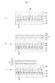
- FIG. 3 shows the manufacturing process of the LED element, where (a) shows the state of the substrate, (b) shows the state in which the buffer layer is grown, and (c) shows the state in which the mask layer is formed. (D) shows the state in which the nanocolumns are grown.
- FIG. 4 shows the manufacturing process of the LED device, in which (a) shows a state in which the n-type layer is grown among the group III nitride semiconductor layers, and (b) shows that the entire group III nitride semiconductor layer is grown.
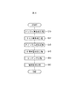
- FIG. 5 is a flow chart showing the manufacturing process of the LED element.
- FIG. 6 shows a modification and is a top view of the LED element showing a state in which nanocolumns are formed using a pattern of a mask layer.
- FIG. 1 to 5 show an embodiment of the present invention
- FIG. 1 is a schematic cross-sectional view of an LED element.
- the LED element 1 as a group III nitride semiconductor device is represented by Al x Ga y In 1-x-y N (0 ⁇ x ⁇ 1, 0 ⁇ y ⁇ 1, x + y ⁇ 1).
- the substrate 20 is made of single crystal 6H-type SiC and has a thermal expansion coefficient of 4.2 ⁇ 10 ⁇ 6 / ° C.
- the nitride semiconductor layer as the semiconductor light emitting unit has a thermal expansion coefficient of 5.6 ⁇ 10 ⁇ 6 / ° C.
- the substrate 20 contains a donor impurity and an acceptor impurity, and when excited by the light emitted from the group III nitride semiconductor layer 10, emits light of a predetermined wavelength by donor-acceptor pair light emission.
- a donor impurity is N and the acceptor impurity is B
- approximately yellow to orange visible light is emitted by excitation of ultraviolet light.
- a bulk SiC substrate is used and the donor impurity is N and the acceptor impurity is Al, approximately blue visible light is emitted by excitation of ultraviolet light.
- pure white visible light can be obtained by simultaneously adding B and Al as acceptor impurities while setting the donor impurity to N, and by making the SiC porous, the emission wavelength on the short wavelength side
- the light emission wavelength of the substrate can be arbitrarily changed.
- Buffer layer 30 is made of a material represented by the formula Al x Ga y In 1-x over y N (0 ⁇ x ⁇ 1,0 ⁇ y ⁇ 1, x + y ⁇ 1).
- the buffer layer 30 represented by the formula Al x Ga 1 -xN (0 ⁇ x ⁇ 1) and containing Al is used.
- a mask layer 40 made of an amorphous material is formed on the buffer layer 30, a mask layer 40 made of an amorphous material is formed. On the mask layer 40, a pattern 42 for forming a nanocolumn 50 described later is formed.
- SiO 2 is used as the mask layer 40.
- other materials such as SiN x (0 ⁇ x) may be used as the mask layer 40.
- a material of the mask layer 40 it is also possible to use a material such as Al 2 O 3 , W, or the like. These materials may be polycrystalline or amorphous.
- the pattern 42 of the mask layer 40 has a shape in which circular holes 44 are arranged at the intersections of an equilateral triangular lattice.
- the diameter and spacing of the holes 44 are arbitrary, for example, the diameter of the holes 44 may be 50 to 1000 nm, and the spacing between adjacent holes 44 may be 100 to 1000 nm.
- Nanocolumns 50 are grown on the substrate 20 through the buffer layer 30 and the pattern 42 of the mask layer 40.
- GaN is used as the nanocolumns 50.
- the nanocolumns 50 are grown corresponding to the patterns 42, and the dislocation density is smaller than when grown without the mask layer 40.
- the nanocolumns 50 are formed in a cylindrical shape, and can have an aspect ratio of 1 or more.
- the nanocolumns 50 may have a shape other than a cylinder, as long as they are formed in a columnar shape.
- Group III nitride semiconductor layer 10 is formed on mask layer 40.
- the group III nitride semiconductor layer 10 has an n-type layer 12, a multiple quantum well active layer 14, a p-type cladding layer 16, and a p-type contact layer 18 in this order from the substrate 20 side.
- a part of the group III nitride semiconductor layer 10 is removed by etching, a part of the n-type layer 12 is exposed, and the n-side electrode 60 is provided on the exposed part. Further, a p-side electrode 62 is formed on the p-type contact layer 18.
- the n-type layer 12 is formed of n-GaN doped with a predetermined amount of n-type dopant (eg, Si).
- the multiple quantum well active layer 14 has a multiple quantum well structure formed of In x Ga 1 -xN (0 ⁇ x ⁇ 1) / Al y Ga 1 ⁇ y N (0 ⁇ y ⁇ 1).
- the p-type cladding layer 16 and the p-type contact layer 18 are each formed of p-GaN doped with a predetermined amount of p-type dopant (eg, Mg).
- the n-type layer 12 to the p-type contact layer 18 are formed by epitaxial growth of a group III nitride semiconductor.
- a voltage is applied to the first conductive type layer and the second conductive type layer at least including the first conductive type layer, the active layer and the second conductive type layer, the active layer is formed by recombination of electrons and holes.
- the layer structure of the group III nitride semiconductor layer 10 is arbitrary as long as light is emitted.
- the n-side electrode 60 is formed on the n-type layer 12 and made of, for example, Ni / Au, and is formed by a vacuum evaporation method, a sputtering method, a CVD (Chemical Vapor Deposition) method or the like.
- the p-side electrode 62 is formed on the p-type contact layer 18, and made of, for example, ITO (Indium Tin Oxide), and is formed by a vacuum evaporation method, a sputtering method, a CVD (Chemical Vapor Deposition) method or the like.
- FIG.3 and FIG.4 is a schematic cross section of a LED element
- FIG. 5 is a flowchart of the manufacturing method of a LED element.
- FIGS. 3 and 4 are illustrated in unit of one element so as to correspond to FIG. 1 for the sake of explanation, actually they are in the state of the wafer before element division, and other elements are continuous on the left and right as well. Are formed.
- the substrate 20 is prepared by preparing bulk crystals of, for example, about 30 mm by bulk growth of sublimation method, and passing through processes such as peripheral grinding, slicing, surface grinding, surface polishing, etc. There is.
- the thickness of the substrate 20 is arbitrary, it is, for example, 250 ⁇ m.
- the buffer layer 30 is epitaxially grown on the substrate 20 (buffer layer forming step S10 (FIG. 5)).
- the buffer layer 30 is entirely formed on the substrate 20 by sputtering.
- the buffer layer 30 can also be formed by the MOCVD method (Metal Organic Chemical Vapor Deposition) method, the MBE method (Molecular Beam Epitaxy), the HVPE method (Halide Vapor Phase Epitaxy) or the like.
- the buffer layer 30 can also be formed by laser ablation.
- the thickness of the buffer layer 30 is arbitrary, it is, for example, 10 to 200 nm.
- the mask layer 40 is formed on the substrate 20 on which the buffer layer 30 is formed (mask layer forming step S20 (FIG. 5)).
- the mask layer 40 is entirely formed on the buffer layer 30 by vacuum evaporation.
- the thickness of the mask layer 40 is arbitrary, it is, for example, 10 to 200 nm. If it is this thickness, the mask layer 40 will have less of an inhibitory effect on the transmission of light emitted from the active layer.
- the thickness of the mask layer 40 may be set to such an extent that the interference action can be obtained.
- a pattern 44 is formed on the mask layer 40 using a nanoimprint technique.
- the nanocolumns 50 are epitaxially grown using the pattern 42 of the mask layer 40 (nanocolumn growth step S30 (FIG. 5)).
- nanocolumns 50 are selectively grown on the buffer layer 30 by MOCVD using the pattern 42 of the mask layer 40.
- MOCVD metal-organic chemical vapor deposition
- the MBE method, the HVPE method or the like may be used to grow the nanocolumns 50.
- the height of the nanocolumns 50 is optional, for example, 500 nm.
- the dislocation density in the nanocolumns 50 is extremely small as compared with the case where the semiconductor layer is grown entirely on the substrate 20.
- the group III nitride semiconductor layer 10 is grown (semiconductor layer growth step (FIG. 5)).
- the nanocolumns 50 and the group III nitride semiconductor layer 10 are continuously grown by the MOCVD apparatus.
- the V / III ratio is preferably smaller in the nanocolumn growth step than in the semiconductor growth step.
- the V / III ratio can be less than 900 in the nanocolumn growth process. If the V / III ratio is too large at the time of nanocolumn growth, the grown semiconductor can not be formed into a column shape.
- the supply amount of gallium is preferably smaller in the nanocolumn growth step than in the semiconductor layer growth step. In the nanocolumn growth step, if the supply amount of gallium is too large, the semiconductor crystal grows like islands on the mask to be integrated with the nanocolumn, or the shape of the nanocolumn varies.
- the multiple quantum well active layer 14, p-type cladding The layer 16 and the p-type contact layer 18 are sequentially grown from the mask layer 40 side.
- the dislocation density can be reduced.
- the dislocation density of the nanocolumns 50 itself is low, the dislocations propagating from the nanocolumns 50 are extremely small.
- the nanocolumns 50 and the group III nitride semiconductor layer 10 are continuously formed by an MOCVD apparatus, which is a manufacturing process compared to the case where the buffer layer 30 is grown by an MOCVD apparatus. Can be shortened. Thereby, the manufacturing cost of the light emitting element 1 can be reduced.
- the group III nitride semiconductor layer 10 of good quality can be obtained.
- the amorphous mask layer 40 is formed after the growth of the nanocolumns 50 made of group III nitride semiconductors, the surface of the nanocolumns 50 is degraded by the components of the mask layer 40, and the degraded group III nitride semiconductor is used as a seed As the layer 10 is grown, it is not possible to obtain a high quality group III nitride semiconductor layer 10.
- the mask layer 40 is an amorphous material
- the group III nitride semiconductor layer 10 formed on the mask layer 40 and the mask layer 40 are not firmly bonded. Therefore, when excessive stress is generated between the group III nitride semiconductor layer 10 and the mask layer 40, relative displacement between the group III nitride semiconductor layer 10 and the mask layer 40 is allowed. Also by this, the dislocation density of the group III nitride semiconductor layer 10 can be reduced.
- each layer of group III nitride semiconductor layer 10 is arbitrary.
- the thickness of n-type layer 12 is 3 ⁇ m
- the thickness of multiple quantum well active layer 14 is 100 nm
- p-type cladding layer 16 is The thickness can be 80 nm
- the thickness of the p-type contact layer 18 can be 10 nm.
- the thickness of the group III nitride semiconductor layer 10 can be 3 ⁇ m or more.
- the n-side electrode 60 and the p-side electrode 62 are formed using a vacuum evaporation method and a photolithography technique (electrode forming step S60 (FIG. 5)).
- the material of the n-side electrode 60 and the material of the p-side electrode 62 are different, if these materials are the same, the n-side electrode 40 and the p-side electrode 62 can be formed simultaneously.
- heat treatment can be performed at a predetermined temperature and in a predetermined atmosphere for a predetermined time. Thereafter, the LED element 1 is manufactured by dividing it into a plurality of LED elements 1 by dicing.
- the LED element 1 configured as described above, when a voltage is applied to the p-side electrode 62 and the n-side electrode 60, ultraviolet light is emitted from the multiple quantum well active layer 14. Then, after the ultraviolet light is converted into visible light by the substrate 20, it is emitted to the outside.
- the dislocation density of the nanocolumns 50 can be reduced.
- dislocations propagating from the nanocolumns 50 to the group III nitride semiconductor layer 10 formed on the mask layer 40 are dramatically reduced, and the dislocation density of the group III nitride semiconductor layer 10 is also reduced.
- the dislocation generated in the group III nitride semiconductor layer 10 at the time of growth of the group III nitride semiconductor layer 10 has a termination at the interface with the nanocolumn 50, it does not propagate upward. . Therefore, the dislocation density in the group III nitride semiconductor 10 can be properly reduced.
- the buffer layer 30 contains Al, for example, the group III nitride semiconductor and the substrate are mutually different as in the case of directly growing GaN on a substrate made of SiC or Si.
- the group III nitride semiconductor layer 10 can be properly grown on the substrate 20 without reacting violently at the interface of
- the mask layer 40 is formed on the substrate 20, and the nanocolumns 50 are grown using the mask layer 40, and the group III nitride is directly formed on the mask layer 40.
- the semiconductor layer 10 can be grown. Therefore, unlike the prior art, the process of removing the mask layer is unnecessary, and the manufacturing cost can be reduced.
- the buffer layer 30 and the nanocolumns 50 are formed by sputtering, a growth process at a low temperature is possible, and mass productivity is improved.
- the buffer layer can have a good crystal structure with few defects compared to the MOCVD method and the like.
- the present invention is applied to the LED element 1 as a semiconductor device.
- the present invention can be applied to other devices such as an LD element.
- the present invention is also applicable to electronic devices such as field effect transistors and bipolar transistors, solar cells, and the like.
- the nanocolumns 50 are arranged at the intersections of the triangular lattices, but the arrangement state of the nanocolumns can be arbitrarily changed. For example, as shown in FIG. It may be arranged.
- the thing using 6H type SiC as substrate 20 was shown, it is needless to say that it may be 4H type or 15R type, and Si is used as substrate 20. May be Furthermore, the substrate 20 may not have the fluorescent function, and the emission color of the group III nitride semiconductor layer 10 is also arbitrary.
- LED element 10 III nitride semiconductor layer 12 n type layer 14 multiple quantum well active layer 16 p type clad layer 18 p type contact layer 20 substrate 30 buffer layer 40 mask layer 42 hole 44 pattern 50 nanocolumn 60 n side electrode 62 p Mold electrode
Abstract
Description
また、バッファ層をスパッタリング法により形成するため、低温での成長プロセスが可能となり量産性が向上する。さらに、MOCVD法等と比較して欠陥の少ない良質な結晶構造を得ることができる。 According to the method of manufacturing a group III nitride semiconductor device, a mask layer is formed on the substrate, and the nanocolumns are grown using the mask layer as it is, and the group III nitride semiconductor layer is formed on the mask layer can do. Therefore, unlike the prior art, the process of removing the mask layer is unnecessary, and the manufacturing cost can be reduced.
In addition, since the buffer layer is formed by sputtering, a growth process at a low temperature is possible, and mass productivity is improved. Furthermore, a good crystal structure with few defects can be obtained as compared to the MOCVD method and the like.
10 III族窒化物半導体層
12 n型層
14 多重量子井戸活性層
16 p型クラッド層
18 p型コンタクト層
20 基板
30 バッファ層
40 マスク層
42 孔
44 パターン
50 ナノコラム
60 n側電極
62 p型電極 1
Claims (5)
- SiC又はSiからなる基板と、
前記基板上に形成され、所定のパターンが形成されたマスク層と、
前記マスク層の前記パターンを通じて選択的に成長され、III族窒化物半導体からなるナノコラムと、
前記マスク層上に前記ナノコラムより高く成長されたIII族窒化物半導体層と、を備えたIII族窒化物半導体デバイス。 A substrate made of SiC or Si;
A mask layer formed on the substrate and having a predetermined pattern formed thereon;
Nano-columns selectively grown through the pattern of the mask layer and made of a group III nitride semiconductor,
And a group III nitride semiconductor layer grown higher than the nanocolumns on the mask layer. - 前記マスク層は、非晶質材料からなる請求項1に記載のIII族窒化物半導体デバイス。 The III-nitride semiconductor device according to claim 1, wherein the mask layer is made of an amorphous material.
- 前記基板と前記マスク層の間に、Alを含むIII族窒化物半導体からなるバッファ層を備える請求項2に記載のIII族窒化物半導体デバイス。 The group III nitride semiconductor device according to claim 2, further comprising: a buffer layer made of a group III nitride semiconductor containing Al between the substrate and the mask layer.
- 請求項1から3に記載のIII族窒化物半導体デバイスの製造方法であって、
前記基板上に前記マスク層を形成するマスク層形成工程と、
前記マスク層の前記パターンを通じてIII族窒化物半導体からなる前記ナノコラムを選択的に成長させるナノコラム成長工程と、
前記マスク層上にIII族窒化物半導体層を成長させる半導体層成長工程と、を含むIII族窒化物半導体デバイスの製造方法。 A method of manufacturing a group III nitride semiconductor device according to any one of claims 1 to 3,
A mask layer forming step of forming the mask layer on the substrate;
A nano-column growth step of selectively growing the nano-columns made of a group III nitride semiconductor through the pattern of the mask layer;
A semiconductor layer growth step of growing a group III nitride semiconductor layer on the mask layer, and a method of manufacturing a group III nitride semiconductor device. - 請求項3に記載のIII族窒化物半導体デバイスの製造方法であって、
前記基板上にスパッタリング法により前記バッファ層を形成するバッファ層形成工程と、
前記バッファ層が形成された前記基板上に前記マスク層を形成するマスク層形成工程と、
前記マスク層の前記パターンを通じてIII族窒化物半導体からなる前記ナノコラムを選択的に成長させるナノコラム成長工程と、
前記マスク層上にIII族窒化物半導体層を成長させる半導体層成長工程と、を含むIII族窒化物半導体デバイスの製造方法。 A method of manufacturing a group III nitride semiconductor device according to claim 3, wherein
A buffer layer forming step of forming the buffer layer on the substrate by a sputtering method;
A mask layer forming step of forming the mask layer on the substrate on which the buffer layer is formed;
A nano-column growth step of selectively growing the nano-columns made of a group III nitride semiconductor through the pattern of the mask layer;
A semiconductor layer growth step of growing a group III nitride semiconductor layer on the mask layer, and a method of manufacturing a group III nitride semiconductor device.
Priority Applications (4)
| Application Number | Priority Date | Filing Date | Title |
|---|---|---|---|
| CN201180031709.2A CN102959739B (en) | 2010-12-08 | 2011-11-25 | III nitride semiconductor devices and manufacture method thereof |
| JP2012547783A JP5932664B2 (en) | 2010-12-08 | 2011-11-25 | Group III nitride semiconductor device and manufacturing method thereof |
| EP11847760.3A EP2571065A4 (en) | 2010-12-08 | 2011-11-25 | Group iii nitride semiconductor device and method for producing same |
| US13/704,963 US9142619B2 (en) | 2010-12-08 | 2011-11-25 | Group III nitride semiconductor device and method for manufacturing the same |
Applications Claiming Priority (2)
| Application Number | Priority Date | Filing Date | Title |
|---|---|---|---|
| JP2010-273209 | 2010-12-08 | ||
| JP2010273209 | 2010-12-08 |
Publications (1)
| Publication Number | Publication Date |
|---|---|
| WO2012077513A1 true WO2012077513A1 (en) | 2012-06-14 |
Family
ID=46207007
Family Applications (1)
| Application Number | Title | Priority Date | Filing Date |
|---|---|---|---|
| PCT/JP2011/077240 WO2012077513A1 (en) | 2010-12-08 | 2011-11-25 | Group iii nitride semiconductor device and method for producing same |
Country Status (5)
| Country | Link |
|---|---|
| US (1) | US9142619B2 (en) |
| EP (1) | EP2571065A4 (en) |
| JP (1) | JP5932664B2 (en) |
| CN (1) | CN102959739B (en) |
| WO (1) | WO2012077513A1 (en) |
Cited By (2)
| Publication number | Priority date | Publication date | Assignee | Title |
|---|---|---|---|---|
| JP2014076928A (en) * | 2012-10-12 | 2014-05-01 | Waseda Univ | Template substrate |
| JP2021531231A (en) * | 2018-04-22 | 2021-11-18 | エピノバテック、アクチボラグEpinovatech Ab | Reinforcing thin film device |
Families Citing this family (13)
| Publication number | Priority date | Publication date | Assignee | Title |
|---|---|---|---|---|
| FR2997551B1 (en) * | 2012-10-26 | 2015-12-25 | Commissariat Energie Atomique | METHOD OF MANUFACTURING SEMICONDUCTOR STRUCTURE AND SEMICONDUCTOR COMPONENT COMPRISING SUCH A STRUCTURE |
| CN103489974B (en) * | 2013-08-30 | 2016-04-20 | 华灿光电股份有限公司 | A kind of GaN base LED epitaxial slice and preparation method thereof |
| CN104638068B (en) * | 2013-11-07 | 2018-08-24 | 上海蓝光科技有限公司 | A kind of substrat structure and preparation method thereof being used for the growth of III-V group-III nitride |
| KR102175320B1 (en) | 2014-04-07 | 2020-11-06 | 엘지이노텍 주식회사 | Light emitting device and lighting system having the same |
| CN107611004B (en) * | 2017-08-14 | 2020-01-31 | 南京大学 | method for preparing self-supporting GaN substrate material |
| DE102019103492A1 (en) * | 2019-02-12 | 2020-08-13 | OSRAM Opto Semiconductors Gesellschaft mit beschränkter Haftung | OPTOELECTRONIC COMPONENT |
| EP3836227A1 (en) | 2019-12-11 | 2021-06-16 | Epinovatech AB | Semiconductor layer structure |
| EP3855530A1 (en) | 2020-01-24 | 2021-07-28 | Epinovatech AB | Solid-state battery |
| EP3866189B1 (en) | 2020-02-14 | 2022-09-28 | Epinovatech AB | A mmic front-end module |
| EP3879706A1 (en) | 2020-03-13 | 2021-09-15 | Epinovatech AB | Field-programmable gate array device |
| CN112802930B (en) * | 2021-04-15 | 2021-07-06 | 至芯半导体(杭州)有限公司 | Method for manufacturing group III nitride substrate and semiconductor device |
| EP4101945A1 (en) | 2021-06-09 | 2022-12-14 | Epinovatech AB | A device for performing electrolysis of water, and a system thereof |
| DE102022101575A1 (en) * | 2022-01-24 | 2023-07-27 | OSRAM Opto Semiconductors Gesellschaft mit beschränkter Haftung | PROCESS FOR MANUFACTURING A VARIETY OF OPTOELECTRONIC SEMICONDUCTOR CHIPS AND OPTOELECTRONIC SEMICONDUCTOR CHIP |
Citations (9)
| Publication number | Priority date | Publication date | Assignee | Title |
|---|---|---|---|---|
| JPH07273367A (en) * | 1994-04-01 | 1995-10-20 | Mitsubishi Cable Ind Ltd | Manufacture of semiconductor substrate and light-emitting device |
| JP2006128627A (en) * | 2004-10-29 | 2006-05-18 | Samsung Electro Mech Co Ltd | Nitride semiconductor element using nano rod, and its manufacturing method |
| JP2007027298A (en) * | 2005-07-14 | 2007-02-01 | Matsushita Electric Works Ltd | Semiconductor light emitting device and lighting device using the same, and method of manufacturing the same |
| JP4153455B2 (en) | 2003-11-28 | 2008-09-24 | 学校法人 名城大学 | Phosphor and light emitting diode |
| JP2009009978A (en) * | 2007-06-26 | 2009-01-15 | Panasonic Electric Works Co Ltd | Compound semiconductor device and lighting apparatus using the same, and method of manufacturing compound semiconductor device |
| JP2009542560A (en) * | 2006-03-10 | 2009-12-03 | エステイーシー.ユーエヌエム | Pulsed growth and application of GaN nanowires in group III nitride semiconductor substrate materials and devices |
| JP2010515651A (en) * | 2007-01-12 | 2010-05-13 | クナノ アーベー | Multiple nitride nanowires and method of manufacturing the same |
| JP2010518615A (en) | 2007-02-09 | 2010-05-27 | ナノガン リミテッド | Semiconductor device manufacturing method and semiconductor device |
| JP2010157603A (en) * | 2008-12-26 | 2010-07-15 | Fujitsu Ltd | Method of manufacturing compound semiconductor device |
Family Cites Families (8)
| Publication number | Priority date | Publication date | Assignee | Title |
|---|---|---|---|---|
| KR100646696B1 (en) * | 2004-03-10 | 2006-11-23 | 주식회사 실트론 | Nitride semiconductor device and method for manufacturing the same |
| GB2428681B (en) | 2004-03-24 | 2008-10-29 | Meijo University Educational Foundation | Phosphor |
| US20080318003A1 (en) * | 2004-08-31 | 2008-12-25 | Agency For Science, Technology And Research | Nanostructures and Method of Making the Same |
| CN101443887B (en) * | 2006-03-10 | 2011-04-20 | Stc.Unm公司 | Pulsed growth of GAN nanowires and applications in group III nitride semiconductor substrate materials and devices |
| GB2436398B (en) * | 2006-03-23 | 2011-08-24 | Univ Bath | Growth method using nanostructure compliant layers and HVPE for producing high quality compound semiconductor materials |
| KR100767284B1 (en) * | 2006-03-27 | 2007-10-17 | 학교법인 포항공과대학교 | ZnO microstructures and the preparation method thereof |
| JP5066825B2 (en) | 2006-03-31 | 2012-11-07 | 新神戸電機株式会社 | Lead acid battery |
| JP5112761B2 (en) * | 2007-06-26 | 2013-01-09 | パナソニック株式会社 | COMPOUND SEMICONDUCTOR ELEMENT, LIGHTING DEVICE USING SAME, AND METHOD FOR PRODUCING COMPOUND SEMICONDUCTOR ELEMENT |
-
2011
- 2011-11-25 EP EP11847760.3A patent/EP2571065A4/en not_active Withdrawn
- 2011-11-25 WO PCT/JP2011/077240 patent/WO2012077513A1/en active Application Filing
- 2011-11-25 CN CN201180031709.2A patent/CN102959739B/en not_active Expired - Fee Related
- 2011-11-25 JP JP2012547783A patent/JP5932664B2/en not_active Expired - Fee Related
- 2011-11-25 US US13/704,963 patent/US9142619B2/en not_active Expired - Fee Related
Patent Citations (9)
| Publication number | Priority date | Publication date | Assignee | Title |
|---|---|---|---|---|
| JPH07273367A (en) * | 1994-04-01 | 1995-10-20 | Mitsubishi Cable Ind Ltd | Manufacture of semiconductor substrate and light-emitting device |
| JP4153455B2 (en) | 2003-11-28 | 2008-09-24 | 学校法人 名城大学 | Phosphor and light emitting diode |
| JP2006128627A (en) * | 2004-10-29 | 2006-05-18 | Samsung Electro Mech Co Ltd | Nitride semiconductor element using nano rod, and its manufacturing method |
| JP2007027298A (en) * | 2005-07-14 | 2007-02-01 | Matsushita Electric Works Ltd | Semiconductor light emitting device and lighting device using the same, and method of manufacturing the same |
| JP2009542560A (en) * | 2006-03-10 | 2009-12-03 | エステイーシー.ユーエヌエム | Pulsed growth and application of GaN nanowires in group III nitride semiconductor substrate materials and devices |
| JP2010515651A (en) * | 2007-01-12 | 2010-05-13 | クナノ アーベー | Multiple nitride nanowires and method of manufacturing the same |
| JP2010518615A (en) | 2007-02-09 | 2010-05-27 | ナノガン リミテッド | Semiconductor device manufacturing method and semiconductor device |
| JP2009009978A (en) * | 2007-06-26 | 2009-01-15 | Panasonic Electric Works Co Ltd | Compound semiconductor device and lighting apparatus using the same, and method of manufacturing compound semiconductor device |
| JP2010157603A (en) * | 2008-12-26 | 2010-07-15 | Fujitsu Ltd | Method of manufacturing compound semiconductor device |
Non-Patent Citations (2)
| Title |
|---|
| See also references of EP2571065A4 |
| STEPHEN D. HERSEE ET AL.: "The Controlled Growth of GaN Nanowires", NANO LETTERS, vol. 6, no. 8, 26 July 2006 (2006-07-26), pages 1808 - 1811, XP055031460 * |
Cited By (2)
| Publication number | Priority date | Publication date | Assignee | Title |
|---|---|---|---|---|
| JP2014076928A (en) * | 2012-10-12 | 2014-05-01 | Waseda Univ | Template substrate |
| JP2021531231A (en) * | 2018-04-22 | 2021-11-18 | エピノバテック、アクチボラグEpinovatech Ab | Reinforcing thin film device |
Also Published As
| Publication number | Publication date |
|---|---|
| JPWO2012077513A1 (en) | 2014-05-19 |
| EP2571065A1 (en) | 2013-03-20 |
| EP2571065A4 (en) | 2016-03-23 |
| US20130126907A1 (en) | 2013-05-23 |
| JP5932664B2 (en) | 2016-06-08 |
| CN102959739B (en) | 2016-05-18 |
| CN102959739A (en) | 2013-03-06 |
| US9142619B2 (en) | 2015-09-22 |
Similar Documents
| Publication | Publication Date | Title |
|---|---|---|
| JP5932664B2 (en) | Group III nitride semiconductor device and manufacturing method thereof | |
| JP5280004B2 (en) | Light emitting device and manufacturing method thereof | |
| KR101646064B1 (en) | Method of manufacture for nitride semiconductor light emitting element, wafer, and nitride semiconductor light emitting element | |
| RU2315135C2 (en) | Method of growing nonpolar epitaxial heterostructures based on group iii element nitrides | |
| US8664687B2 (en) | Nitride semiconductor light-emitting device and process for producing the same | |
| JP6324654B2 (en) | GaN thin film structure, manufacturing method thereof, and semiconductor device including the same | |
| CN102576780B (en) | High-quality non-polar/semi-polar semiconductor element on an unevenly patterned substrate and a production method therefor | |
| JP2010098336A (en) | GaN SEMICONDUCTOR LIGHT-EMITTING ELEMENT AND MANUFACTURING METHOD THEREOF | |
| KR100809229B1 (en) | Nitride semiconductor light emitting device and manufacturing method of the same | |
| US20100012954A1 (en) | Vertical III-Nitride Light Emitting Diodes on Patterned Substrates with Embedded Bottom Electrodes | |
| EP2492953A2 (en) | Nitride based light emitting device using patterned lattice buffer layer and method of manufacturing the same | |
| KR101181182B1 (en) | Light Emitting Device using nitrogen compound semiconductor and producing method thereof | |
| JP2010135859A (en) | Method of manufacturing semiconductor light emitting device | |
| KR100820836B1 (en) | Method for manufacturing light emitting diode | |
| WO2009002073A1 (en) | Method for fabricating semiconductor device | |
| KR20140073646A (en) | Gallium nitride substrate and a fabricating method thereof to reduce stress | |
| JPH08293473A (en) | Epitaxial wafer and compound semiconductor light emitting element and their manufacture | |
| KR102099877B1 (en) | Method for fabricating nitride semiconductor device | |
| JP5946333B2 (en) | Group III nitride semiconductor device and manufacturing method thereof | |
| KR20110135237A (en) | Semiconductor light emitting diode and method for fabricating the same | |
| KR20130055976A (en) | Light emitting diode having void layer and method of fabricating the same | |
| KR100793443B1 (en) | Substrate structure for semiconductor device based on nitride and method of manufacturing the same | |
| JP5190343B2 (en) | Manufacturing method of semiconductor device | |
| KR100713031B1 (en) | Gallium nitride-based compound semiconductor | |
| KR101116904B1 (en) | Method for manufacturing nitride semiconductor crystals and light emitting devices |
Legal Events
| Date | Code | Title | Description |
|---|---|---|---|
| WWE | Wipo information: entry into national phase |
Ref document number: 201180031709.2 Country of ref document: CN |
|
| 121 | Ep: the epo has been informed by wipo that ep was designated in this application |
Ref document number: 11847760 Country of ref document: EP Kind code of ref document: A1 |
|
| REEP | Request for entry into the european phase |
Ref document number: 2011847760 Country of ref document: EP |
|
| WWE | Wipo information: entry into national phase |
Ref document number: 2011847760 Country of ref document: EP |
|
| WWE | Wipo information: entry into national phase |
Ref document number: 13704963 Country of ref document: US |
|
| ENP | Entry into the national phase |
Ref document number: 2012547783 Country of ref document: JP Kind code of ref document: A |
|
| NENP | Non-entry into the national phase |
Ref country code: DE |