WO2012077408A1 - 画像処理装置及び画像処理方法 - Google Patents
画像処理装置及び画像処理方法 Download PDFInfo
- Publication number
- WO2012077408A1 WO2012077408A1 PCT/JP2011/073657 JP2011073657W WO2012077408A1 WO 2012077408 A1 WO2012077408 A1 WO 2012077408A1 JP 2011073657 W JP2011073657 W JP 2011073657W WO 2012077408 A1 WO2012077408 A1 WO 2012077408A1
- Authority
- WO
- WIPO (PCT)
- Prior art keywords
- matrix
- unit
- quantization matrix
- quantization
- size
- Prior art date
Links
- 238000012545 processing Methods 0.000 title claims abstract description 135
- 238000003672 processing method Methods 0.000 title claims description 7
- 239000011159 matrix material Substances 0.000 claims abstract description 788
- 238000013139 quantization Methods 0.000 claims abstract description 505
- 238000006243 chemical reaction Methods 0.000 claims description 26
- 230000001131 transforming effect Effects 0.000 claims description 3
- 230000009466 transformation Effects 0.000 abstract description 14
- 238000000034 method Methods 0.000 description 42
- 230000008569 process Effects 0.000 description 33
- 230000015654 memory Effects 0.000 description 31
- 239000000872 buffer Substances 0.000 description 25
- 239000013001 matrix buffer Substances 0.000 description 22
- 238000003384 imaging method Methods 0.000 description 21
- 238000004891 communication Methods 0.000 description 20
- 101000702394 Homo sapiens Signal peptide peptidase-like 2A Proteins 0.000 description 18
- 238000010586 diagram Methods 0.000 description 18
- 230000005540 biological transmission Effects 0.000 description 16
- 230000006870 function Effects 0.000 description 15
- 238000004364 calculation method Methods 0.000 description 13
- 230000008707 rearrangement Effects 0.000 description 13
- 238000003860 storage Methods 0.000 description 13
- 238000001914 filtration Methods 0.000 description 11
- 101000988591 Homo sapiens Minor histocompatibility antigen H13 Proteins 0.000 description 10
- 238000009825 accumulation Methods 0.000 description 10
- 230000004048 modification Effects 0.000 description 10
- 238000012986 modification Methods 0.000 description 10
- 230000003287 optical effect Effects 0.000 description 10
- 230000005236 sound signal Effects 0.000 description 10
- 101000828788 Homo sapiens Signal peptide peptidase-like 3 Proteins 0.000 description 9
- 230000014509 gene expression Effects 0.000 description 6
- 101000702393 Homo sapiens Signal peptide peptidase-like 2B Proteins 0.000 description 5
- 101100309796 Saccharomyces cerevisiae (strain ATCC 204508 / S288c) SEC39 gene Proteins 0.000 description 5
- 238000012937 correction Methods 0.000 description 3
- 239000000284 extract Substances 0.000 description 3
- 238000013213 extrapolation Methods 0.000 description 3
- 239000004065 semiconductor Substances 0.000 description 3
- 230000003044 adaptive effect Effects 0.000 description 2
- 230000006835 compression Effects 0.000 description 2
- 238000007906 compression Methods 0.000 description 2
- 238000009826 distribution Methods 0.000 description 2
- 230000004044 response Effects 0.000 description 2
- 230000009471 action Effects 0.000 description 1
- 230000003321 amplification Effects 0.000 description 1
- 230000010267 cellular communication Effects 0.000 description 1
- 238000005516 engineering process Methods 0.000 description 1
- 210000003127 knee Anatomy 0.000 description 1
- 239000004973 liquid crystal related substance Substances 0.000 description 1
- 238000004519 manufacturing process Methods 0.000 description 1
- 230000007246 mechanism Effects 0.000 description 1
- 238000003199 nucleic acid amplification method Methods 0.000 description 1
- 238000005457 optimization Methods 0.000 description 1
- 238000007639 printing Methods 0.000 description 1
- 239000007787 solid Substances 0.000 description 1
- 239000012536 storage buffer Substances 0.000 description 1
- 238000012360 testing method Methods 0.000 description 1
Images


Classifications
-
- H—ELECTRICITY
- H04—ELECTRIC COMMUNICATION TECHNIQUE
- H04N—PICTORIAL COMMUNICATION, e.g. TELEVISION
- H04N19/00—Methods or arrangements for coding, decoding, compressing or decompressing digital video signals
- H04N19/60—Methods or arrangements for coding, decoding, compressing or decompressing digital video signals using transform coding
-
- G—PHYSICS
- G06—COMPUTING; CALCULATING OR COUNTING
- G06T—IMAGE DATA PROCESSING OR GENERATION, IN GENERAL
- G06T9/00—Image coding
- G06T9/007—Transform coding, e.g. discrete cosine transform
-
- H—ELECTRICITY
- H04—ELECTRIC COMMUNICATION TECHNIQUE
- H04N—PICTORIAL COMMUNICATION, e.g. TELEVISION
- H04N19/00—Methods or arrangements for coding, decoding, compressing or decompressing digital video signals
- H04N19/10—Methods or arrangements for coding, decoding, compressing or decompressing digital video signals using adaptive coding
- H04N19/102—Methods or arrangements for coding, decoding, compressing or decompressing digital video signals using adaptive coding characterised by the element, parameter or selection affected or controlled by the adaptive coding
- H04N19/115—Selection of the code volume for a coding unit prior to coding
-
- H—ELECTRICITY
- H04—ELECTRIC COMMUNICATION TECHNIQUE
- H04N—PICTORIAL COMMUNICATION, e.g. TELEVISION
- H04N19/00—Methods or arrangements for coding, decoding, compressing or decompressing digital video signals
- H04N19/10—Methods or arrangements for coding, decoding, compressing or decompressing digital video signals using adaptive coding
- H04N19/102—Methods or arrangements for coding, decoding, compressing or decompressing digital video signals using adaptive coding characterised by the element, parameter or selection affected or controlled by the adaptive coding
- H04N19/12—Selection from among a plurality of transforms or standards, e.g. selection between discrete cosine transform [DCT] and sub-band transform or selection between H.263 and H.264
- H04N19/122—Selection of transform size, e.g. 8x8 or 2x4x8 DCT; Selection of sub-band transforms of varying structure or type
-
- H—ELECTRICITY
- H04—ELECTRIC COMMUNICATION TECHNIQUE
- H04N—PICTORIAL COMMUNICATION, e.g. TELEVISION
- H04N19/00—Methods or arrangements for coding, decoding, compressing or decompressing digital video signals
- H04N19/10—Methods or arrangements for coding, decoding, compressing or decompressing digital video signals using adaptive coding
- H04N19/102—Methods or arrangements for coding, decoding, compressing or decompressing digital video signals using adaptive coding characterised by the element, parameter or selection affected or controlled by the adaptive coding
- H04N19/124—Quantisation
- H04N19/126—Details of normalisation or weighting functions, e.g. normalisation matrices or variable uniform quantisers
-
- H—ELECTRICITY
- H04—ELECTRIC COMMUNICATION TECHNIQUE
- H04N—PICTORIAL COMMUNICATION, e.g. TELEVISION
- H04N19/00—Methods or arrangements for coding, decoding, compressing or decompressing digital video signals
- H04N19/10—Methods or arrangements for coding, decoding, compressing or decompressing digital video signals using adaptive coding
- H04N19/102—Methods or arrangements for coding, decoding, compressing or decompressing digital video signals using adaptive coding characterised by the element, parameter or selection affected or controlled by the adaptive coding
- H04N19/129—Scanning of coding units, e.g. zig-zag scan of transform coefficients or flexible macroblock ordering [FMO]
-
- H—ELECTRICITY
- H04—ELECTRIC COMMUNICATION TECHNIQUE
- H04N—PICTORIAL COMMUNICATION, e.g. TELEVISION
- H04N19/00—Methods or arrangements for coding, decoding, compressing or decompressing digital video signals
- H04N19/10—Methods or arrangements for coding, decoding, compressing or decompressing digital video signals using adaptive coding
- H04N19/169—Methods or arrangements for coding, decoding, compressing or decompressing digital video signals using adaptive coding characterised by the coding unit, i.e. the structural portion or semantic portion of the video signal being the object or the subject of the adaptive coding
- H04N19/17—Methods or arrangements for coding, decoding, compressing or decompressing digital video signals using adaptive coding characterised by the coding unit, i.e. the structural portion or semantic portion of the video signal being the object or the subject of the adaptive coding the unit being an image region, e.g. an object
- H04N19/172—Methods or arrangements for coding, decoding, compressing or decompressing digital video signals using adaptive coding characterised by the coding unit, i.e. the structural portion or semantic portion of the video signal being the object or the subject of the adaptive coding the unit being an image region, e.g. an object the region being a picture, frame or field
-
- H—ELECTRICITY
- H04—ELECTRIC COMMUNICATION TECHNIQUE
- H04N—PICTORIAL COMMUNICATION, e.g. TELEVISION
- H04N19/00—Methods or arrangements for coding, decoding, compressing or decompressing digital video signals
- H04N19/10—Methods or arrangements for coding, decoding, compressing or decompressing digital video signals using adaptive coding
- H04N19/169—Methods or arrangements for coding, decoding, compressing or decompressing digital video signals using adaptive coding characterised by the coding unit, i.e. the structural portion or semantic portion of the video signal being the object or the subject of the adaptive coding
- H04N19/17—Methods or arrangements for coding, decoding, compressing or decompressing digital video signals using adaptive coding characterised by the coding unit, i.e. the structural portion or semantic portion of the video signal being the object or the subject of the adaptive coding the unit being an image region, e.g. an object
- H04N19/176—Methods or arrangements for coding, decoding, compressing or decompressing digital video signals using adaptive coding characterised by the coding unit, i.e. the structural portion or semantic portion of the video signal being the object or the subject of the adaptive coding the unit being an image region, e.g. an object the region being a block, e.g. a macroblock
-
- H—ELECTRICITY
- H04—ELECTRIC COMMUNICATION TECHNIQUE
- H04N—PICTORIAL COMMUNICATION, e.g. TELEVISION
- H04N19/00—Methods or arrangements for coding, decoding, compressing or decompressing digital video signals
- H04N19/10—Methods or arrangements for coding, decoding, compressing or decompressing digital video signals using adaptive coding
- H04N19/169—Methods or arrangements for coding, decoding, compressing or decompressing digital video signals using adaptive coding characterised by the coding unit, i.e. the structural portion or semantic portion of the video signal being the object or the subject of the adaptive coding
- H04N19/177—Methods or arrangements for coding, decoding, compressing or decompressing digital video signals using adaptive coding characterised by the coding unit, i.e. the structural portion or semantic portion of the video signal being the object or the subject of the adaptive coding the unit being a group of pictures [GOP]
-
- H—ELECTRICITY
- H04—ELECTRIC COMMUNICATION TECHNIQUE
- H04N—PICTORIAL COMMUNICATION, e.g. TELEVISION
- H04N19/00—Methods or arrangements for coding, decoding, compressing or decompressing digital video signals
- H04N19/46—Embedding additional information in the video signal during the compression process
- H04N19/463—Embedding additional information in the video signal during the compression process by compressing encoding parameters before transmission
-
- H—ELECTRICITY
- H04—ELECTRIC COMMUNICATION TECHNIQUE
- H04N—PICTORIAL COMMUNICATION, e.g. TELEVISION
- H04N19/00—Methods or arrangements for coding, decoding, compressing or decompressing digital video signals
- H04N19/60—Methods or arrangements for coding, decoding, compressing or decompressing digital video signals using transform coding
- H04N19/61—Methods or arrangements for coding, decoding, compressing or decompressing digital video signals using transform coding in combination with predictive coding
- H04N19/615—Methods or arrangements for coding, decoding, compressing or decompressing digital video signals using transform coding in combination with predictive coding using motion compensated temporal filtering [MCTF]
-
- H—ELECTRICITY
- H04—ELECTRIC COMMUNICATION TECHNIQUE
- H04N—PICTORIAL COMMUNICATION, e.g. TELEVISION
- H04N19/00—Methods or arrangements for coding, decoding, compressing or decompressing digital video signals
- H04N19/70—Methods or arrangements for coding, decoding, compressing or decompressing digital video signals characterised by syntax aspects related to video coding, e.g. related to compression standards
-
- H—ELECTRICITY
- H04—ELECTRIC COMMUNICATION TECHNIQUE
- H04N—PICTORIAL COMMUNICATION, e.g. TELEVISION
- H04N19/00—Methods or arrangements for coding, decoding, compressing or decompressing digital video signals
- H04N19/80—Details of filtering operations specially adapted for video compression, e.g. for pixel interpolation
- H04N19/82—Details of filtering operations specially adapted for video compression, e.g. for pixel interpolation involving filtering within a prediction loop
-
- H—ELECTRICITY
- H04—ELECTRIC COMMUNICATION TECHNIQUE
- H04N—PICTORIAL COMMUNICATION, e.g. TELEVISION
- H04N7/00—Television systems
- H04N7/24—Systems for the transmission of television signals using pulse code modulation
- H04N7/52—Systems for transmission of a pulse code modulated video signal with one or more other pulse code modulated signals, e.g. an audio signal or a synchronizing signal
-
- H—ELECTRICITY
- H04—ELECTRIC COMMUNICATION TECHNIQUE
- H04N—PICTORIAL COMMUNICATION, e.g. TELEVISION
- H04N19/00—Methods or arrangements for coding, decoding, compressing or decompressing digital video signals
- H04N19/10—Methods or arrangements for coding, decoding, compressing or decompressing digital video signals using adaptive coding
- H04N19/102—Methods or arrangements for coding, decoding, compressing or decompressing digital video signals using adaptive coding characterised by the element, parameter or selection affected or controlled by the adaptive coding
- H04N19/119—Adaptive subdivision aspects, e.g. subdivision of a picture into rectangular or non-rectangular coding blocks
-
- H—ELECTRICITY
- H04—ELECTRIC COMMUNICATION TECHNIQUE
- H04N—PICTORIAL COMMUNICATION, e.g. TELEVISION
- H04N19/00—Methods or arrangements for coding, decoding, compressing or decompressing digital video signals
- H04N19/10—Methods or arrangements for coding, decoding, compressing or decompressing digital video signals using adaptive coding
- H04N19/134—Methods or arrangements for coding, decoding, compressing or decompressing digital video signals using adaptive coding characterised by the element, parameter or criterion affecting or controlling the adaptive coding
- H04N19/136—Incoming video signal characteristics or properties
-
- H—ELECTRICITY
- H04—ELECTRIC COMMUNICATION TECHNIQUE
- H04N—PICTORIAL COMMUNICATION, e.g. TELEVISION
- H04N19/00—Methods or arrangements for coding, decoding, compressing or decompressing digital video signals
- H04N19/10—Methods or arrangements for coding, decoding, compressing or decompressing digital video signals using adaptive coding
- H04N19/134—Methods or arrangements for coding, decoding, compressing or decompressing digital video signals using adaptive coding characterised by the element, parameter or criterion affecting or controlling the adaptive coding
- H04N19/146—Data rate or code amount at the encoder output
- H04N19/147—Data rate or code amount at the encoder output according to rate distortion criteria
-
- H—ELECTRICITY
- H04—ELECTRIC COMMUNICATION TECHNIQUE
- H04N—PICTORIAL COMMUNICATION, e.g. TELEVISION
- H04N19/00—Methods or arrangements for coding, decoding, compressing or decompressing digital video signals
- H04N19/10—Methods or arrangements for coding, decoding, compressing or decompressing digital video signals using adaptive coding
- H04N19/169—Methods or arrangements for coding, decoding, compressing or decompressing digital video signals using adaptive coding characterised by the coding unit, i.e. the structural portion or semantic portion of the video signal being the object or the subject of the adaptive coding
- H04N19/17—Methods or arrangements for coding, decoding, compressing or decompressing digital video signals using adaptive coding characterised by the coding unit, i.e. the structural portion or semantic portion of the video signal being the object or the subject of the adaptive coding the unit being an image region, e.g. an object
- H04N19/174—Methods or arrangements for coding, decoding, compressing or decompressing digital video signals using adaptive coding characterised by the coding unit, i.e. the structural portion or semantic portion of the video signal being the object or the subject of the adaptive coding the unit being an image region, e.g. an object the region being a slice, e.g. a line of blocks or a group of blocks
-
- H—ELECTRICITY
- H04—ELECTRIC COMMUNICATION TECHNIQUE
- H04N—PICTORIAL COMMUNICATION, e.g. TELEVISION
- H04N19/00—Methods or arrangements for coding, decoding, compressing or decompressing digital video signals
- H04N19/10—Methods or arrangements for coding, decoding, compressing or decompressing digital video signals using adaptive coding
- H04N19/169—Methods or arrangements for coding, decoding, compressing or decompressing digital video signals using adaptive coding characterised by the coding unit, i.e. the structural portion or semantic portion of the video signal being the object or the subject of the adaptive coding
- H04N19/18—Methods or arrangements for coding, decoding, compressing or decompressing digital video signals using adaptive coding characterised by the coding unit, i.e. the structural portion or semantic portion of the video signal being the object or the subject of the adaptive coding the unit being a set of transform coefficients
-
- H—ELECTRICITY
- H04—ELECTRIC COMMUNICATION TECHNIQUE
- H04N—PICTORIAL COMMUNICATION, e.g. TELEVISION
- H04N19/00—Methods or arrangements for coding, decoding, compressing or decompressing digital video signals
- H04N19/10—Methods or arrangements for coding, decoding, compressing or decompressing digital video signals using adaptive coding
- H04N19/189—Methods or arrangements for coding, decoding, compressing or decompressing digital video signals using adaptive coding characterised by the adaptation method, adaptation tool or adaptation type used for the adaptive coding
- H04N19/196—Methods or arrangements for coding, decoding, compressing or decompressing digital video signals using adaptive coding characterised by the adaptation method, adaptation tool or adaptation type used for the adaptive coding being specially adapted for the computation of encoding parameters, e.g. by averaging previously computed encoding parameters
-
- H—ELECTRICITY
- H04—ELECTRIC COMMUNICATION TECHNIQUE
- H04N—PICTORIAL COMMUNICATION, e.g. TELEVISION
- H04N19/00—Methods or arrangements for coding, decoding, compressing or decompressing digital video signals
- H04N19/42—Methods or arrangements for coding, decoding, compressing or decompressing digital video signals characterised by implementation details or hardware specially adapted for video compression or decompression, e.g. dedicated software implementation
- H04N19/423—Methods or arrangements for coding, decoding, compressing or decompressing digital video signals characterised by implementation details or hardware specially adapted for video compression or decompression, e.g. dedicated software implementation characterised by memory arrangements
-
- H—ELECTRICITY
- H04—ELECTRIC COMMUNICATION TECHNIQUE
- H04N—PICTORIAL COMMUNICATION, e.g. TELEVISION
- H04N19/00—Methods or arrangements for coding, decoding, compressing or decompressing digital video signals
- H04N19/46—Embedding additional information in the video signal during the compression process
-
- H—ELECTRICITY
- H04—ELECTRIC COMMUNICATION TECHNIQUE
- H04N—PICTORIAL COMMUNICATION, e.g. TELEVISION
- H04N19/00—Methods or arrangements for coding, decoding, compressing or decompressing digital video signals
- H04N19/50—Methods or arrangements for coding, decoding, compressing or decompressing digital video signals using predictive coding
- H04N19/503—Methods or arrangements for coding, decoding, compressing or decompressing digital video signals using predictive coding involving temporal prediction
-
- H—ELECTRICITY
- H04—ELECTRIC COMMUNICATION TECHNIQUE
- H04N—PICTORIAL COMMUNICATION, e.g. TELEVISION
- H04N19/00—Methods or arrangements for coding, decoding, compressing or decompressing digital video signals
- H04N19/50—Methods or arrangements for coding, decoding, compressing or decompressing digital video signals using predictive coding
- H04N19/593—Methods or arrangements for coding, decoding, compressing or decompressing digital video signals using predictive coding involving spatial prediction techniques
-
- H—ELECTRICITY
- H04—ELECTRIC COMMUNICATION TECHNIQUE
- H04N—PICTORIAL COMMUNICATION, e.g. TELEVISION
- H04N19/00—Methods or arrangements for coding, decoding, compressing or decompressing digital video signals
- H04N19/60—Methods or arrangements for coding, decoding, compressing or decompressing digital video signals using transform coding
- H04N19/625—Methods or arrangements for coding, decoding, compressing or decompressing digital video signals using transform coding using discrete cosine transform [DCT]
-
- H—ELECTRICITY
- H04—ELECTRIC COMMUNICATION TECHNIQUE
- H04N—PICTORIAL COMMUNICATION, e.g. TELEVISION
- H04N19/00—Methods or arrangements for coding, decoding, compressing or decompressing digital video signals
- H04N19/90—Methods or arrangements for coding, decoding, compressing or decompressing digital video signals using coding techniques not provided for in groups H04N19/10-H04N19/85, e.g. fractals
Definitions
- the present disclosure relates to an image processing apparatus and an image processing method.
- H. is one of the standard specifications for video coding.
- different quantization steps can be used for each component of orthogonal transform coefficients when image data is quantized.
- the quantization step for each component of the orthogonal transform coefficient can be set based on a quantization matrix (also referred to as a scaling list) defined with a size equivalent to the unit of the orthogonal transform and a reference step value.
- FIG. 4 shows default values (default values) of four types of quantization matrices defined in advance in H.264 / AVC.
- the matrix SL01 is the default value of the quantization matrix.
- the matrix SL02 is the default value of the quantization matrix.
- the matrix SL03 is a default value of the quantization matrix.
- the matrix SL04 is the default value of the quantization matrix.
- the user can specify a unique quantization matrix different from the default value shown in FIG. 19 in the sequence parameter set or the picture parameter set. When the quantization matrix is not used, the quantization step used in the quantization is the same value for all components.
- HEVC High Efficiency Video Coding
- CU Coding Unit
- SCU Smallest Coding Unit
- one coding unit may be divided into one or more orthogonal transform units, that is, one or more transform units (TU).
- TU transform units
- any of 4 ⁇ 4, 8 ⁇ 8, 16 ⁇ 16, and 32 ⁇ 32 can be used. Accordingly, a quantization matrix can also be specified for each of these transform unit candidate sizes.
- Non-Patent Document 2 specifies a plurality of quantization matrix candidates for one transform unit size within one picture, and is adaptive for each block from the viewpoint of RD (Rate-Distortion) optimization. We propose to select a quantization matrix.
- JCTVC-B205 “Test Model Consideration”, Joint Collaborative Team on Video Coding (JCT-VC) of ITU-T SG16 WP3 and ISO / IEC JTC1 / SC29 / WG11 2nd Meeting: Geneva, CH, 21-28 July, 2010
- VCEG-AD06 “Adaptive Quantization Matrix Selection on KTA Software”, ITU-Telecommunications Standardization Sector STUDY GROUP 16 Question 6 Video Coding Experts Group (VCEG) 30th Meeting: Hangzhou, China, 23-24 2006
- the technology according to the present disclosure is intended to provide an image processing apparatus and an image processing method capable of suppressing an increase in code amount when the number of quantization matrices increases.
- a selection unit that selects a transform unit used for inverse orthogonal transform of decoded image data from a plurality of transform units having different sizes, and corresponding to the transform unit of the first size.
- the generation unit that generates the second quantization matrix corresponding to the transform unit of the second size from the first quantization matrix and the transform unit of the second size are selected by the selection unit.
- an image processing apparatus comprising: an inverse quantization unit that inversely quantizes transform coefficient data of the image data using the second quantization matrix generated by the generation unit.
- the image processing apparatus can typically be realized as an image decoding apparatus that decodes an image.
- the generation unit includes: matrix information that identifies the first quantization matrix, and a prediction matrix of the second size predicted from the first quantization matrix and the second quantization matrix.
- the second quantization matrix may be generated using difference information representing the difference.
- the generation unit may acquire the matrix information and the difference information from a sequence parameter set or a picture parameter set.
- the generation unit May be the second quantization matrix.
- the first size may be a minimum size among the sizes of the plurality of conversion units.
- the second size is larger than the first size
- the generation unit is configured as the element between the first element and the second element adjacent to each other in the first quantization matrix.
- the prediction matrix may be calculated by duplicating the first element or the second element.
- the second size is larger than the first size, and the generation unit linearly changes an element between the first element and the second element adjacent to each other in the first quantization matrix.
- the prediction matrix may be calculated by interpolation.
- the second size may be twice the first size on one side.
- the second size may be smaller than the first size, and the generation unit may calculate the prediction matrix by thinning out elements of the first quantization matrix.
- the second size is smaller than the first size, and the generation unit calculates the prediction matrix by calculating an average of a plurality of elements adjacent to each other in the first quantization matrix. May be.
- the generation unit The second quantization matrix may be generated from the quantization matrix.
- An image processing method includes inversely quantizing the transform coefficient data of the image data using the second quantization matrix generated from the quantization matrix.
- a selection unit that selects a transform unit used for orthogonal transform of encoded image data from a plurality of transform units having different sizes, and the selection unit selects the transform unit.
- a quantization unit that quantizes transform coefficient data generated by orthogonally transforming the image data in transform units using a quantization matrix corresponding to the selected transform unit; and a transform unit having a first size
- an image processing apparatus comprising: an encoding unit that encodes information for generating a second quantization matrix corresponding to a second size transform unit from a first quantization matrix corresponding to .
- the image processing apparatus can typically be realized as an image encoding apparatus that encodes an image.
- selecting a transform unit used for orthogonal transform of image data to be encoded from a plurality of transform units having different sizes and selecting the image in the selected transform unit.
- the transform coefficient data generated by orthogonal transform of the data is quantized using a quantization matrix corresponding to the selected transform unit, and the first quantum corresponding to the transform unit of the first size. Encoding an information for generating a second quantization matrix corresponding to a transform unit of the second size from the quantization matrix is provided.
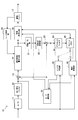
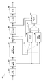
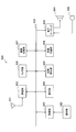
- FIG. 1 is a block diagram illustrating an example of a configuration of an image encoding device 10 according to an embodiment.
- an image encoding device 10 includes an analog / digital (A / D) conversion unit 11, a rearrangement buffer 12, a subtraction unit 13, an orthogonal transformation / quantization unit 14, a lossless encoding unit 16, and an accumulation buffer. 17, rate control unit 18, inverse quantization unit 21, inverse orthogonal transformation unit 22, addition unit 23, deblock filter 24, frame memory 25, selector 26, intra prediction unit 30, motion search unit 40, and mode selection unit 50 Is provided.
- a / D analog / digital
- the A / D converter 11 converts an image signal input in an analog format into image data in a digital format, and outputs a series of digital image data to the rearrangement buffer 12.
- the rearrangement buffer 12 rearranges the images included in the series of image data input from the A / D conversion unit 11.
- the rearrangement buffer 12 rearranges the images according to the GOP (Group of Pictures) structure related to the encoding process, and then outputs the rearranged image data to the subtraction unit 13, the intra prediction unit 30, and the motion search unit 40. To do.
- GOP Group of Pictures
- the subtraction unit 13 is supplied with image data input from the rearrangement buffer 12 and predicted image data selected by the mode selection unit 50 described later.
- the subtraction unit 13 calculates prediction error data that is a difference between the image data input from the rearrangement buffer 12 and the prediction image data input from the mode selection unit 50, and orthogonally transforms and quantizes the calculated prediction error data.
- the orthogonal transform / quantization unit 14 performs orthogonal transform and quantization on the prediction error data input from the subtraction unit 13, and converts the quantized transform coefficient data (hereinafter referred to as quantized data) into the lossless encoding unit 16 and The result is output to the inverse quantization unit 21.
- the bit rate of the quantized data output from the orthogonal transform / quantization unit 14 is controlled based on the rate control signal from the rate control unit 18. The detailed configuration of the orthogonal transform / quantization unit 14 will be further described later.
- the lossless encoding unit 16 includes quantized data input from the orthogonal transform / quantization unit 14, information for generating a quantization matrix on the decoding side, and intra prediction or interface selected by the mode selection unit 50.
- Information about the prediction is supplied.
- the information regarding intra prediction may include, for example, prediction mode information indicating an optimal intra prediction mode for each block.
- the information regarding inter prediction may include, for example, prediction mode information for motion vector prediction for each block, differential motion vector information, reference image information, and the like.
- the lossless encoding unit 16 generates an encoded stream by performing lossless encoding processing on the quantized data.
- the lossless encoding by the lossless encoding unit 16 may be variable length encoding or arithmetic encoding, for example.
- the lossless encoding unit 16 multiplexes information for generating a quantization matrix, which will be described in detail later, in the header of the encoded stream (for example, a sequence parameter set and a picture parameter set). Further, the lossless encoding unit 16 multiplexes the information related to intra prediction or information related to inter prediction described above in the header of the encoded stream. Then, the lossless encoding unit 16 outputs the generated encoded stream to the accumulation buffer 17.
- the accumulation buffer 17 temporarily accumulates the encoded stream input from the lossless encoding unit 16 using a storage medium such as a semiconductor memory.
- the accumulation buffer 17 outputs the accumulated encoded stream at a rate corresponding to the bandwidth of the transmission path (or the output line from the image encoding device 10).
- the rate control unit 18 monitors the free capacity of the accumulation buffer 17. Then, the rate control unit 18 generates a rate control signal according to the free capacity of the accumulation buffer 17 and outputs the generated rate control signal to the orthogonal transform / quantization unit 14. For example, the rate control unit 18 generates a rate control signal for reducing the bit rate of the quantized data when the free capacity of the storage buffer 17 is small. For example, when the free capacity of the accumulation buffer 17 is sufficiently large, the rate control unit 18 generates a rate control signal for increasing the bit rate of the quantized data.
- the inverse quantization unit 21 performs an inverse quantization process on the quantized data input from the orthogonal transform / quantization unit 14. Then, the inverse quantization unit 21 outputs transform coefficient data acquired by the inverse quantization process to the inverse orthogonal transform unit 22.
- the inverse orthogonal transform unit 22 restores the prediction error data by performing an inverse orthogonal transform process on the transform coefficient data input from the inverse quantization unit 21. Then, the inverse orthogonal transform unit 22 outputs the restored prediction error data to the addition unit 23.
- the addition unit 23 generates decoded image data by adding the restored prediction error data input from the inverse orthogonal transform unit 22 and the predicted image data input from the mode selection unit 50. Then, the addition unit 23 outputs the generated decoded image data to the deblock filter 24 and the frame memory 25.
- the deblocking filter 24 performs a filtering process for reducing block distortion that occurs during image coding.
- the deblocking filter 24 removes block distortion by filtering the decoded image data input from the adding unit 23, and outputs the decoded image data after filtering to the frame memory 25.
- the frame memory 25 stores the decoded image data input from the adder 23 and the decoded image data after filtering input from the deblock filter 24 using a storage medium.
- the selector 26 reads out the decoded image data before filtering used for intra prediction from the frame memory 25 and supplies the read decoded image data to the intra prediction unit 30 as reference image data. Further, the selector 26 reads out the filtered decoded image data used for inter prediction from the frame memory 25 and supplies the read decoded image data to the motion search unit 40 as reference image data.
- the intra prediction unit 30 performs an intra prediction process in each intra prediction mode based on the image data to be encoded input from the rearrangement buffer 12 and the decoded image data supplied via the selector 26. For example, the intra prediction unit 30 evaluates the prediction result in each intra prediction mode using a predetermined cost function. Then, the intra prediction unit 30 selects an intra prediction mode in which the cost function value is minimum, that is, an intra prediction mode in which the compression rate is the highest as the optimal intra prediction mode. Further, the intra prediction unit 30 outputs information related to intra prediction, such as prediction mode information indicating the optimal intra prediction mode, predicted image data, and cost function value, to the mode selection unit 50.
- the motion search unit 40 performs inter prediction processing (interframe prediction processing) based on the image data to be encoded input from the rearrangement buffer 12 and the decoded image data supplied via the selector 26. For example, the motion search unit 40 evaluates the prediction result in each prediction mode using a predetermined cost function. Next, the motion search unit 40 selects a prediction mode with the smallest cost function value, that is, a prediction mode with the highest compression rate, as the optimum prediction mode. Further, the motion search unit 40 generates predicted image data according to the optimal prediction mode. Then, the motion search unit 40 outputs information related to inter prediction including prediction mode information representing the selected optimal prediction mode, prediction image data, and information related to inter prediction such as a cost function value to the mode selection unit 50.
- inter prediction processing interframe prediction processing
- the mode selection unit 50 compares the cost function value related to intra prediction input from the intra prediction unit 30 with the cost function value related to inter prediction input from the motion search unit 40. And the mode selection part 50 selects the prediction method with few cost function values among intra prediction and inter prediction.
- the mode selection unit 50 outputs information on the intra prediction to the lossless encoding unit 16 and outputs the predicted image data to the subtraction unit 13 and the addition unit 23.
- the mode selection unit 50 outputs the above-described information regarding inter prediction to the lossless encoding unit 16 and outputs the predicted image data to the subtraction unit 13 and the addition unit 23.
- FIG. 2 is a block diagram illustrating an example of a detailed configuration of the orthogonal transform / quantization unit 14 of the image encoding device 10 illustrated in FIG. 1.
- the orthogonal transform / quantization unit 14 includes a selection unit 110, an orthogonal transform unit 120, a quantization unit 130, a quantization matrix buffer 140, and a matrix processing unit 15.
- the selection unit 110 selects a transform unit (TU) used for orthogonal transform of image data to be encoded from a plurality of transform units having different sizes.
- Candidates for the sizes of conversion units that can be selected by the selection unit 110 are, for example, H.264.
- H.264 / AVC includes 4 ⁇ 4 and 8 ⁇ 8
- HEVC includes 4 ⁇ 4, 8 ⁇ 8, 16 ⁇ 16, and 32 ⁇ 32.
- the selection unit 110 may select any conversion unit according to the size or image quality of the image to be encoded, the performance of the apparatus, or the like.
- the selection of the conversion unit by the selection unit 110 may be hand-tuned by a user who develops the apparatus. Then, the selection unit 110 outputs information specifying the size of the selected transform unit to the orthogonal transform unit 120, the quantization unit 130, the lossless encoding unit 16, and the inverse quantization unit 21.
- the orthogonal transform unit 120 performs orthogonal transform on the image data (that is, prediction error data) supplied from the subtraction unit 13 in the transform unit selected by the selection unit 110.
- the orthogonal transform executed by the orthogonal transform unit 120 may be, for example, discrete cosine transform (DCT) or Karoonen-Loeve transform. Then, the orthogonal transform unit 120 outputs transform coefficient data acquired by the orthogonal transform process to the quantization unit 130.
- DCT discrete cosine transform
- Karoonen-Loeve transform Karoonen-Loeve transform
- the quantization unit 130 quantizes the transform coefficient data generated by the orthogonal transform unit 120 using a quantization matrix corresponding to the transform unit selected by the selection unit 110. Further, the quantization unit 130 changes the bit rate of the output quantized data by switching the quantization step based on the rate control signal from the rate control unit 18.
- the quantization unit 130 causes the quantization matrix buffer 140 to store a set of quantization matrices respectively corresponding to a plurality of transform units that can be selected by the selection unit 110. For example, when there are conversion unit candidates of four types of sizes of 4 ⁇ 4, 8 ⁇ 8, 16 ⁇ 16, and 32 ⁇ 32 as in HEVC, four types corresponding to these four types of sizes respectively. A set of quantization matrices can be stored by the quantization matrix buffer 140. In addition, when a predetermined quantization matrix as illustrated in FIG. 19 is used for a certain size, it is necessary to use a predetermined quantization matrix (do not use a user-defined quantization matrix). Only the indicated flag may be stored by the quantization matrix buffer 140 in association with the size.
- a set of quantization matrices that may be used by the quantization unit 130 may typically be set for each sequence of the encoded stream. Further, the quantization unit 130 may update the set of quantization matrices set for each sequence for each picture. Information for controlling the setting and updating of such a set of quantization matrices can be inserted into, for example, a sequence parameter set and a picture parameter set.
- the quantization matrix buffer 140 temporarily stores a set of quantization matrices respectively corresponding to a plurality of transform units that can be selected by the selection unit 110 using a storage medium such as a semiconductor memory. .
- a set of quantization matrices stored in the quantization matrix buffer 140 is referred to when processing is performed by the matrix processing unit 150 described below.
- the matrix processing unit 150 refers to a set of quantization matrices stored in the quantization matrix buffer 140 for each sequence of the encoded stream and for each picture, and transform units of a certain size. Information for generating a quantization matrix corresponding to one or more other transform units of the size from the quantization matrix corresponding to.
- the size of the transform unit that is the basis for generating the quantization matrix may typically be the smallest size among the sizes of the plurality of transform units. That is, when there are four types of size conversion unit candidates of 4 ⁇ 4, 8 ⁇ 8, 16 ⁇ 16, and 32 ⁇ 32 as in HEVC, other sizes of 4 ⁇ 4 quantization matrices are used.
- Information for generating a quantization matrix may be generated.
- the information generated by the matrix processing unit 15 may include basic matrix information and difference matrix information described later, for example. Then, the information generated by the matrix processing unit 150 is output to the lossless encoding unit 16 and can be inserted into the header of the encoded stream.
- a quantization matrix having a larger size is generated mainly from a quantization matrix having a minimum size.
- the present invention is not limited to this example, and a smaller-sized quantization matrix and / or a larger-sized quantization matrix may be generated from a non-minimum-sized quantization matrix.
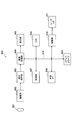
- FIG. 3 is a block diagram illustrating an example of a more detailed configuration of the matrix processing unit 150 of the orthogonal transform / quantization unit 14 illustrated in FIG.
- the matrix processing unit 150 includes a prediction unit 152 and a difference calculation unit 154.
- the prediction unit 152 obtains a set of quantization matrices stored in the quantization matrix buffer 140, and obtains a second quantum having a larger size from the first quantization matrix included in the obtained set. Predict the quantization matrix.
- a 4 ⁇ 4 quantization matrix SL1 is defined as follows:
- the 8 ⁇ 8 prediction matrix PSL2 predicted from the quantization matrix SL1 by the prediction unit 152 can be calculated, for example, according to the following prediction formula (2):
- the prediction matrix PSL2 is a matrix generated by duplicating one of the two elements as an element between two adjacent elements in the quantization matrix SL1.
- the prediction matrix PSL2 may be calculated from the quantization matrix SL1 according to the following prediction formula (3):
- the prediction matrix PSL2 is a matrix generated by linearly interpolating elements between two elements adjacent to each other in the quantization matrix SL1. Note that although the rightmost element of the prediction matrix PSL2 of the prediction formula (3) is duplicated from the left one element, the rightmost element may be calculated not by duplication but by linear extrapolation. Similarly, the element at the lower end of the prediction matrix PSL2 of the prediction formula (3) may also be calculated by linear extrapolation instead of being copied from the element one above. For example, the 8 ⁇ 8 component PSL2 8,8 of the prediction matrix PSL2 is a 33 in the prediction equation (3), but can also be calculated according to linear extrapolation as follows:
- the prediction equation (2) is an equation that can generate the prediction matrix PSL2 with a lower calculation cost than the prediction equation (3).
- the prediction formula (3) it is possible to obtain a smooth prediction matrix closer to the originally used quantization matrix. Therefore, if the prediction formula (3) is used, each element of the difference matrix, which will be described later, can be brought close to zero, and the amount of information to be encoded can be reduced.
- prediction expressions (2) and (3) are merely examples of usable prediction expressions, and any other prediction expression may also be used.
- the prediction unit 152 When the prediction unit 152 generates the prediction matrix PSL2 from the quantization matrix SL1, the prediction unit 152 outputs the generated prediction matrix PSL2 to the difference calculation unit 154. Also, the prediction unit 152 predicts a 16 ⁇ 16 prediction matrix PSL3 from the 8 ⁇ 8 quantization matrix SL2 included in the set of quantization matrices, and outputs the prediction matrix PSL3 to the difference calculation unit 154, for example. Further, the prediction unit 152 predicts the 32 ⁇ 32 prediction matrix PSL4 from the 16 ⁇ 16 quantization matrix SL3 included in the set of quantization matrices, and outputs the prediction matrix PSL4 to the difference calculation unit 154.
- the prediction of the prediction matrix PSL3 and the prediction matrix PSL4 may also be performed according to a prediction expression equivalent to the prediction expression (2) or (3) described above. Further, the prediction unit 152 outputs basic matrix information for specifying the 4 ⁇ 4 quantization matrix SL1 used as a basis for generating the above-described prediction matrices PSL2, PSL3, and PSL4 to the lossless encoding unit 16.
- the difference calculation unit 154 generates difference matrices DSL2, DSL3, and DSL4 that represent differences between the prediction matrices PSL2, PSL3, and PSL4 input from the prediction unit 152 and the corresponding quantization matrices SL2, SL3, and SL4. , Respectively calculated according to equations (5) to (7):
- the difference calculation unit 154 outputs difference matrix information representing these difference matrices DSL2, DSL3, and DSL4 to the lossless encoding unit 16.
- the matrix processing unit 150 uses the predetermined quantization matrix without executing prediction and difference calculation of the quantization matrix of the size. Only the flag indicating this is output to the lossless encoding unit 16 in association with the corresponding size. Also, if the difference between the prediction matrix and the quantization matrix is zero, the difference calculation unit 154 outputs only the flag indicating that no difference exists to the lossless encoding unit 16 instead of outputting the difference matrix information. Can be output. Further, when the quantization matrix is not updated at the timing of picture switching, the matrix processing unit 150 can output only a flag indicating that the quantization matrix is not updated to the lossless encoding unit 16.
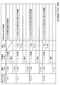
- FIG. 4 is an explanatory diagram showing an example of information inserted in the sequence parameter set in the present embodiment.
- matrix type flag “difference flag”, and “(encoded) matrix information” are information encoded for each quantization matrix size (transformation unit (TU) size). Three types of information are shown.
- the matrix type flag is a flag that specifies which one of the quantization matrix defined by the user and the default quantization matrix is used for each size. If the matrix type flag is “1” for a certain size, the quantization matrix of that size is defined by the user. If the matrix type flag is “0” for a certain size, the quantization matrix of that size is a default quantization matrix. When the matrix type flag is “0”, the matrix information, the difference matrix information, and the difference flag described below are not encoded.
- the difference flag is a flag indicating whether or not there is a difference between the prediction matrix and the quantization matrix when the matrix type flag is “1: user defined” for each size. If the difference flag is “1” for a certain size, there is a difference between the prediction matrix and the quantization matrix of that size, and the difference matrix information is encoded. If the difference flag is “0” for a certain size, the difference matrix information of that size is not encoded. Note that the difference flag is not encoded for the size (for example, 4 ⁇ 4) that is the basis of prediction, regardless of the matrix type flag.
- FIG. 5 is an explanatory diagram showing an example of information inserted in the picture parameter set in the present embodiment.
- “update flag”, “matrix type flag”, “difference flag”, and “(encoded) are used as information encoded for each quantization matrix size (transformation unit (TU) size).
- the four types of information are shown. Among these, the meaning of the matrix type flag and the difference flag is the same as the flag of the same name in the sequence parameter set described with reference to FIG.
- the update flag is a flag indicating whether or not the quantization matrix should be updated at the timing of picture switching for each size. If the update flag is “1” for a certain size, the quantization matrix of that size is updated. If the update flag is “0”, the quantization matrix of that size is not updated, and the quantization matrix set in the previous picture or the current sequence is used as it is. When the update flag is “0”, the matrix type flag, the difference flag, and the difference matrix information (matrix information in the case of 4 ⁇ 4) are not encoded for the size.
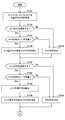
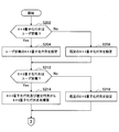
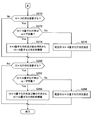
- FIGS. 6A and 6B are flowcharts showing a first example of a processing flow during encoding according to the present embodiment.
- the processing shown in the flowchart can be executed mainly by the matrix processing unit 150 and the lossless encoding unit 16 for each sequence of the encoded stream.
- the matrix processing unit 150 acquires a set of quantization matrices used by the quantization unit 130 in the sequence from the quantization matrix buffer 140 (step S100).
- quantization matrices corresponding to sizes of 4 ⁇ 4, 8 ⁇ 8, 16 ⁇ 16, and 32 ⁇ 32 are included in the set of quantization matrices.
- the matrix processing unit 150 determines whether or not the 4 ⁇ 4 quantization matrix is a matrix defined by the user (step S102).
- the matrix processing unit 150 determines whether or not the 8 ⁇ 8 quantization matrix is a matrix defined by the user (step S112).
- the matrix processing unit 150 for example, from the 4 ⁇ 4 quantization matrix according to the prediction formula (2) or (3) described above.
- An 8 ⁇ 8 prediction matrix is calculated (step S114).
- the matrix processing unit 150 determines whether or not the 16 ⁇ 16 quantization matrix is a matrix defined by the user (step S122).
- the matrix processing unit 150 calculates a 16 ⁇ 16 prediction matrix from the 8 ⁇ 8 quantization matrix (step S124).
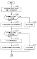
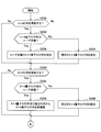
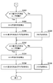
- FIG. 7A and 7B are flowcharts showing a second example of the processing flow during encoding according to the present embodiment.
- the processing shown in the flowchart can be executed mainly by the matrix processing unit 150 and the lossless encoding unit 16 for each picture of the encoded stream.
- the matrix processing unit 150 acquires a set of quantization matrices used by the quantization unit 130 in the picture from the quantization matrix buffer 140 (step S150).
- quantization matrices corresponding to sizes of 4 ⁇ 4, 8 ⁇ 8, 16 ⁇ 16, and 32 ⁇ 32 are included in the set of quantization matrices.
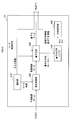
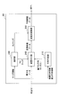
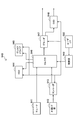
- FIG. 8 is a block diagram illustrating an example of the configuration of the image decoding device 60 according to an embodiment.
- an image decoding device 60 includes an accumulation buffer 61, a lossless decoding unit 62, an inverse quantization / inverse orthogonal transform unit 63, an addition unit 65, a deblock filter 66, a rearrangement buffer 67, a D / A (Digital to Analogue) conversion unit 68, frame memory 69, selectors 70 and 71, intra prediction unit 80, and motion compensation unit 90.
- an image decoding device 60 includes an accumulation buffer 61, a lossless decoding unit 62, an inverse quantization / inverse orthogonal transform unit 63, an addition unit 65, a deblock filter 66, a rearrangement buffer 67, a D / A (Digital to Analogue) conversion unit 68, frame memory 69, selectors 70 and 71, intra prediction unit 80, and motion compensation unit 90.
- the accumulation buffer 61 temporarily accumulates the encoded stream input via the transmission path using a storage medium.
- the lossless decoding unit 62 decodes the encoded stream input from the accumulation buffer 61 according to the encoding method used at the time of encoding. In addition, the lossless decoding unit 62 decodes information multiplexed in the header area of the encoded stream.
- the information multiplexed in the header region of the encoded stream is, for example, basic matrix information and difference matrix information for generating the above-described quantization matrix, information on intra prediction in the block header, and information on inter prediction. Can be included.
- the lossless decoding unit 62 outputs the decoded data and the information for generating the quantization matrix to the inverse quantization / inverse orthogonal transform unit 63. Further, the lossless decoding unit 62 outputs information related to intra prediction to the intra prediction unit 80. Further, the lossless decoding unit 62 outputs information related to inter prediction to the motion compensation unit 90.
- the inverse quantization / inverse orthogonal transform unit 63 generates prediction error data by performing inverse quantization and inverse orthogonal transform on the quantized data input from the lossless decoding unit 62. Then, the inverse quantization / inverse orthogonal transform unit 63 outputs the generated prediction error data to the addition unit 65.
- the addition unit 65 adds the prediction error data input from the inverse quantization / inverse orthogonal transform unit 63 and the predicted image data input from the selector 71 to generate decoded image data. Then, the addition unit 65 outputs the generated decoded image data to the deblock filter 66 and the frame memory 69.
- the deblocking filter 66 removes block distortion by filtering the decoded image data input from the adding unit 65, and outputs the decoded image data after filtering to the rearrangement buffer 67 and the frame memory 69.
- the rearrangement buffer 67 rearranges the images input from the deblock filter 66 to generate a series of time-series image data. Then, the rearrangement buffer 67 outputs the generated image data to the D / A conversion unit 68.
- the D / A converter 68 converts the digital image data input from the rearrangement buffer 67 into an analog image signal. Then, the D / A conversion unit 68 displays an image by outputting an analog image signal to a display (not shown) connected to the image decoding device 60, for example.
- the frame memory 69 stores the decoded image data before filtering input from the adding unit 65 and the decoded image data after filtering input from the deblocking filter 66 using a storage medium.
- the selector 70 switches the output destination of the image data from the frame memory 69 between the intra prediction unit 80 and the motion compensation unit 90 for each block in the image according to the mode information acquired by the lossless decoding unit 62. .
- the selector 70 outputs the decoded image data before filtering supplied from the frame memory 69 to the intra prediction unit 80 as reference image data.
- the selector 70 outputs the decoded image data after filtering supplied from the frame memory 69 to the motion compensation unit 90 as reference image data.
- the selector 71 sets the output source of the predicted image data to be supplied to the adding unit 65 for each block in the image according to the mode information acquired by the lossless decoding unit 62 between the intra prediction unit 80 and the motion compensation unit 90. Switch between. For example, the selector 71 supplies the prediction image data output from the intra prediction unit 80 to the adding unit 65 when the intra prediction mode is designated. The selector 71 supplies the predicted image data output from the motion compensation unit 90 to the adding unit 65 when the inter prediction mode is designated.
- the intra prediction unit 80 performs in-screen prediction of pixel values based on information related to intra prediction input from the lossless decoding unit 62 and reference image data from the frame memory 69, and generates predicted image data. Then, the intra prediction unit 80 outputs the generated predicted image data to the selector 71.
- the motion compensation unit 90 performs motion compensation processing based on the inter prediction information input from the lossless decoding unit 62 and the reference image data from the frame memory 69, and generates predicted image data. Then, the motion compensation unit 90 outputs the generated predicted image data to the selector 71.
- FIG. 9 is a block diagram illustrating an example of a detailed configuration of the inverse quantization / inverse orthogonal transform unit 63 of the image decoding device 60 illustrated in FIG. 8.
- the inverse quantization / inverse orthogonal transform unit 63 includes a matrix generation unit 210, a selection unit 230, an inverse quantization unit 240, and an inverse orthogonal transform unit 250.
- the matrix generation unit 210 converts a quantization matrix corresponding to a certain one size conversion unit into another one or more size conversion units for each sequence of the encoded stream and for each picture. Generate a corresponding quantization matrix.
- the size of the transform unit that is the basis for generating the quantization matrix may typically be the smallest size among the sizes of the plurality of transform units.
- the matrix generation unit 210 uses 8 ⁇ 8, 16 ⁇ 16, and 32 ⁇ 32 quantums using difference matrix information for a larger size from a minimum size 4 ⁇ 4 quantization matrix. Generate a quantization matrix.
- the selection unit 230 selects a transform unit (TU) used for inverse orthogonal transform of decoded image data from a plurality of transform units having different sizes.
- Candidates for the size of the conversion unit that can be selected by the selection unit 230 are, for example, H.264.
- H.264 / AVC includes 4 ⁇ 4 and 8 ⁇ 8
- HEVC includes 4 ⁇ 4, 8 ⁇ 8, 16 ⁇ 16, and 32 ⁇ 32.
- the selection unit 230 may select a conversion unit based on the LCU, SCU, and split_flag included in the header of the encoded stream. Then, the selection unit 230 outputs information specifying the size of the selected transform unit to the inverse quantization unit 240 and the inverse orthogonal transform unit 250.
- the inverse quantization unit 240 uses the quantization matrix corresponding to the transform unit selected by the selection unit 230 to inversely quantize the transform coefficient data quantized when the image is encoded.
- the quantization matrix used for the inverse quantization process includes a matrix generated by the matrix generation unit 210. That is, for example, when a conversion unit of 8 ⁇ 8, 16 ⁇ 16, or 32 ⁇ 32 is selected by the selection unit 230, a 4 ⁇ 4 is generated by the matrix generation unit 210 as a quantization matrix corresponding to the selected conversion unit. A quantization matrix generated from the quantization matrix of can be used. Then, the inverse quantization unit 240 outputs the inversely quantized transform coefficient data to the inverse orthogonal transform unit 250.
- the inverse orthogonal transform unit 250 inverts the transform coefficient data inversely quantized by the inverse quantizer 240 in the selected transform unit in accordance with the orthogonal transform method used at the time of encoding. Prediction error data is generated by performing orthogonal transformation. Then, the inverse orthogonal transform unit 250 outputs the generated prediction error data to the addition unit 65.
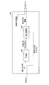
- FIG. 10 is a block diagram illustrating an example of a more detailed configuration of the matrix generation unit 210 of the inverse quantization / inverse orthogonal transform unit 63 illustrated in FIG. 9.
- the matrix generation unit 210 includes a basic matrix acquisition unit 212, a difference acquisition unit 214, a prediction unit 216, a reconstruction unit 218, and a quantization matrix buffer 220.
- the basic matrix acquisition unit 212 acquires basic matrix information input from the lossless decoding unit 62.
- the basic matrix information is information specifying the 4 ⁇ 4 quantization matrix SL1 having the minimum size as described above. Then, the basic matrix acquisition unit 212 stores the 4 ⁇ 4 quantization matrix SL1 specified from the acquired basic matrix information in the quantization matrix buffer 220. Note that if the matrix type flag acquired for each sequence or for each picture is “0”, the basic matrix acquisition unit 212 quantizes a predetermined 4 ⁇ 4 quantization matrix without acquiring basic matrix information. Stored in the quantization matrix buffer 220.
- the basic matrix acquisition unit 212 does not update the quantization matrix SL1 stored in the quantization matrix buffer 220 by the previous process. In addition, the basic matrix acquisition unit 212 outputs the 4 ⁇ 4 quantization matrix SL1 to the prediction unit 216.
- the difference acquisition unit 214 acquires difference matrix information input from the lossless decoding unit 62.
- the difference matrix information is a difference matrix representing a difference between the prediction matrices PSL2, PSL3, and PSL4 predicted from the 4 ⁇ 4 quantization matrix SL1 and the quantization matrices SL2, SL3, and SL4. This is information for specifying DSL2, DSL3, and DSL4.
- the difference acquisition unit 214 outputs the difference matrices DSL2, DSL3, and DSL4 specified by the difference matrix information to the reconstruction unit 218.
- the difference acquisition unit 214 acquires the corresponding size without acquiring the difference matrix information if the matrix type flag acquired for each sequence or each picture is “0” or the difference flag is “0”.
- the difference matrix of is a zero matrix. Also, if the update flag acquired for each picture is “0”, the difference acquisition unit 214 does not output a difference matrix for the corresponding size.
- Prediction unit The prediction unit 216 uses the basic matrix input from the basic matrix acquisition unit 212, that is, the 4 ⁇ 4 quantization matrix SL1 in the present embodiment, and the prediction formula used when encoding the image. In accordance with (for example, the above-described prediction formula (2) or (3)), an 8 ⁇ 8 prediction matrix PSL2 having a larger size is calculated. Also, the prediction unit 216 calculates a 16 ⁇ 16 prediction matrix PSL3 from the quantization matrix SL2 reconstructed by the reconstruction unit 218 using the calculated 8 ⁇ 8 prediction matrix PSL2. Further, the prediction unit 216 calculates a 32 ⁇ 32 prediction matrix PSL4 from the quantization matrix SL3 reconstructed by the reconstruction unit 218 using the calculated 16 ⁇ 16 prediction matrix PSL3.
- the prediction unit 216 outputs the prediction matrices PSL2, PSL3, and PSL4 to the reconstruction unit 218, respectively. Note that the prediction unit 216 does not generate a prediction matrix for a size whose matrix type flag is “0”, and uses a predetermined quantization matrix for calculation of a larger size prediction matrix. In addition, the basic matrix acquisition unit 212 does not generate a prediction matrix even for a size for which the update flag is “0”, and the quantization matrix generated in the previous process is not calculated in order to calculate a larger size prediction matrix. use.
- the reconstruction unit 218 adds the prediction matrices PSL2, PSL3, and PSL4 input from the prediction unit 216 and the difference matrices DSL2, DSL3, and DSL4 input from the difference acquisition unit 214, thereby Reconstruct the quantization matrices SL2, SL3 and SL4, respectively:
- the reconstruction unit 218 stores the reconstructed 8 ⁇ 8, 16 ⁇ 16, and 32 ⁇ 32 quantization matrices SL2, SL3, and SL4 in the quantization matrix buffer 220. If the matrix type flag acquired for each sequence or for each picture is “0”, the reconstruction unit 218 stores a predetermined quantization matrix in the quantization matrix buffer 220 as a quantization matrix of a corresponding size. Let In addition, if the update flag acquired for each picture is “0”, the basic matrix acquisition unit 212 has a corresponding size of the quantization matrix SL2, SL3, or SL4 stored in the quantization matrix buffer 220 by the previous processing. Do not update.
- Quantization Matrix Buffer temporarily stores the quantization matrix SL1 specified by the basic matrix acquisition unit 212 and the quantization matrices SL2, SL3, and SL4 reconstructed by the reconstruction unit 218.
- quantization matrices SL1, SL2, SL3, and SL4 stored by the quantization matrix buffer 220 are used for inverse quantization processing by the inverse quantization unit 240 of the quantized transform coefficient data.
- the configuration of the inverse quantization / inverse orthogonal transform unit 63 of the image decoding device 60 described in this section is also applied to the inverse quantization unit 21 and the inverse orthogonal transform unit 22 of the image coding device 10 illustrated in FIG. Can be done.
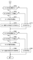
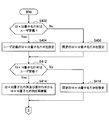
- Flow of processing at the time of decoding according to an embodiment> 11A and 11B are flowcharts showing a first example of the flow of processing at the time of decoding according to the present embodiment.
- the process shown in the flowchart can be executed by the matrix generation unit 210 mainly for each sequence of the encoded stream.
- the matrix generation unit 210 determines whether or not the 4 ⁇ 4 quantization matrix is a matrix defined by the user based on the matrix type flag included in the sequence parameter set of the sequence. Determination is made (step S202). When the 4 ⁇ 4 quantization matrix is a matrix defined by the user, the matrix generation unit 210 sets a 4 ⁇ 4 quantization matrix using the basic matrix information (that is, the quantization matrix). (Stored in the buffer 220) (step S204). On the other hand, if the 4 ⁇ 4 quantization matrix is a default matrix, the matrix generation unit 210 sets a default 4 ⁇ 4 quantization matrix (step S206).
- the matrix generation unit 210 determines whether or not the 8 ⁇ 8 quantization matrix is a matrix defined by the user (step S212).
- the matrix generation unit 210 uses, for example, a 4 ⁇ 4 quantization matrix from 8 ⁇ 8 according to the prediction formula (2) or (3) described above.
- a ⁇ 8 prediction matrix is calculated, and the calculated prediction matrix and the 8 ⁇ 8 difference matrix are added.
- an 8 ⁇ 8 quantization matrix is reconstructed (step S214). If the 8 ⁇ 8 difference flag is “0”, the difference matrix is a zero matrix, and the 8 ⁇ 8 prediction matrix can be set as it is as a quantization matrix.
- the matrix generation unit 210 sets a default 8 ⁇ 8 quantization matrix (step S216).
- the matrix generation unit 210 determines whether or not the 16 ⁇ 16 quantization matrix is a matrix defined by the user (step S222). If the 16 ⁇ 16 quantization matrix is a matrix defined by the user, the matrix generation unit 210 calculates a 16 ⁇ 16 prediction matrix from the 8 ⁇ 8 quantization matrix, and calculates the calculated prediction matrix. And the 16 ⁇ 16 difference matrix. Thereby, a 16 ⁇ 16 quantization matrix is reconstructed (step S224). If the 16 ⁇ 16 difference flag is “0”, the difference matrix is a zero matrix, and the 16 ⁇ 16 prediction matrix can be set as it is as a quantization matrix. On the other hand, when the 16 ⁇ 16 quantization matrix is a default matrix, the matrix generation unit 210 sets a default 16 ⁇ 16 quantization matrix (step S226).
- the matrix generation unit 210 determines whether or not the 32 ⁇ 32 quantization matrix is a matrix defined by the user (step S232).
- the matrix generation unit 210 calculates a 32 ⁇ 32 prediction matrix from the 16 ⁇ 16 quantization matrix, and calculates the calculated prediction matrix. And the 32 ⁇ 32 difference matrix are added. Thereby, a 32 ⁇ 32 quantization matrix is reconstructed (step S234). If the 32 ⁇ 32 difference flag is “0”, the difference matrix is a zero matrix, and the 32 ⁇ 32 prediction matrix can be set as it is as a quantization matrix.
- the matrix generation unit 210 sets a default 32 ⁇ 32 quantization matrix (step S236).
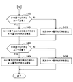
- FIGS. 12A and 12B are flowcharts showing a second example of the flow of processing at the time of decoding according to the present embodiment.
- the process shown in the flowchart can be executed mainly by the matrix generation unit 210 for each picture of the encoded stream.
- the matrix generation unit 210 determines whether or not a 4 ⁇ 4 quantization matrix is updated in the picture based on an update flag included in the picture parameter set (step S250). .
- the matrix generation unit 210 determines whether the new 4 ⁇ 4 quantization matrix is a matrix defined by the user based on the matrix type flag. Determination is made (step S252). If the 4 ⁇ 4 quantization matrix is a matrix defined by the user, the matrix generation unit 210 sets a 4 ⁇ 4 quantization matrix using the basic matrix information (step S254). On the other hand, when the 4 ⁇ 4 quantization matrix is a default matrix, the matrix generation unit 210 sets a default 4 ⁇ 4 quantization matrix (step S256).
- the matrix generation unit 210 determines whether or not the 8 ⁇ 8 quantization matrix is updated in the picture based on the update flag (step S260). Here, if the 8 ⁇ 8 quantization matrix is not updated, the processing of steps S262 to S266 is skipped.
- the matrix generation unit 210 determines whether the new 8 ⁇ 8 quantization matrix is a matrix defined by the user based on the matrix type flag. Determination is made (step S262).
- the matrix generation unit 210 determines whether the 4 ⁇ 4 quantization matrix is updated regardless of whether the 4 ⁇ 4 quantization matrix is updated.
- An 8 ⁇ 8 prediction matrix is calculated from the ⁇ 4 quantization matrix, and the calculated prediction matrix and the 8 ⁇ 8 difference matrix are added. Thereby, an 8 ⁇ 8 quantization matrix is reconstructed (step S264). If the 8 ⁇ 8 difference flag is “0”, the difference matrix is a zero matrix, and the 8 ⁇ 8 prediction matrix can be set as it is as a quantization matrix. On the other hand, if the 8 ⁇ 8 quantization matrix is a default matrix, the matrix generation unit 210 sets a default 8 ⁇ 8 quantization matrix (step S266).
- the matrix generation unit 210 determines whether or not the 16 ⁇ 16 quantization matrix is updated in the picture based on the update flag (step S270). Here, if the 16 ⁇ 16 quantization matrix is not updated, the processing of steps S272 to S276 is skipped.
- the matrix generation unit 210 determines whether the new 16 ⁇ 16 quantization matrix is a matrix defined by the user based on the matrix type flag. Determination is made (step S272).
- the matrix generation unit 210 determines whether the 8 ⁇ 8 quantization matrix is updated regardless of whether the 8 ⁇ 8 quantization matrix is updated.
- a 16 ⁇ 16 prediction matrix is calculated from the ⁇ 8 quantization matrix, and the calculated prediction matrix and the 16 ⁇ 16 difference matrix are added. Thereby, a 16 ⁇ 16 quantization matrix is reconstructed (step S274). If the 16 ⁇ 16 difference flag is “0”, the difference matrix is a zero matrix, and the 16 ⁇ 16 prediction matrix can be set as it is as a quantization matrix. On the other hand, when the 16 ⁇ 16 quantization matrix is a default matrix, the matrix generation unit 210 sets a default 16 ⁇ 16 quantization matrix (step S276).
- the matrix generation unit 210 determines whether or not the 32 ⁇ 32 quantization matrix is updated in the picture based on the update flag (step S280).
- the matrix generation unit 210 determines whether or not the new 32 ⁇ 32 quantization matrix is a matrix defined by the user based on the matrix type flag. Determination is made (step S282).
- the matrix generation unit 210 determines whether the 16 ⁇ 16 quantization matrix is updated regardless of whether the 16 ⁇ 16 quantization matrix is updated.
- a 32 ⁇ 32 prediction matrix is calculated from the ⁇ 16 quantization matrix, and the calculated prediction matrix and the 32 ⁇ 32 difference matrix are added. Thereby, a 32 ⁇ 32 quantization matrix is reconstructed (step S284). If the 32 ⁇ 32 difference flag is “0”, the difference matrix is a zero matrix, and the 32 ⁇ 32 prediction matrix can be set as it is as a quantization matrix. On the other hand, when the 32 ⁇ 32 quantization matrix is a default matrix, the matrix generation unit 210 sets a default 32 ⁇ 32 quantization matrix (step S286).
- the present invention is not limited to this example, and multiple types of quantization matrices may be set for the size of one transform unit.
- the sequence parameter set and the picture parameter set include an additional flag indicating which of the multiple types of quantization matrices should be the basis for the prediction of the larger size quantization matrix.
- multiple types of quantization matrices may be set for one transform unit size, and the quantization matrices may be selectively switched for each slice or block within one picture.
- an 8 ⁇ 8 quantization matrix SL2 is defined as follows:
- the prediction unit 152 of the orthogonal transform / quantization unit 14 of the image encoding device 10 can calculate a 4 ⁇ 4 prediction matrix PSL1 from the quantization matrix SL2 according to, for example, the following prediction formula (12):
- the prediction matrix PSL1 is a matrix generated by thinning out the elements of the quantization matrix SL2 every other row and every other column.
- the position of the element to be thinned out is not limited to the example of the prediction formula (12), and may be another position. Further, by increasing the number of elements to be thinned out, a prediction matrix having a side size of 1 ⁇ 4 or less can be generated from the quantization matrix.
- the prediction matrix PSL1 may be calculated from the quantization matrix SL2 according to the following prediction equation (13):
- the prediction matrix PSL1 is a matrix generated by calculating the average of four elements adjacent to each other vertically and horizontally in the quantization matrix SL2 as one element of the prediction matrix PSL1. Also, by calculating the average of more (for example, 16) elements that are adjacent to each other vertically and horizontally, a prediction matrix having a side size of 1 ⁇ 4 or less can be generated from the quantization matrix. Instead of the average value as in the prediction formula (13), other types of representative values such as a median value, a minimum value, or a maximum value may be calculated from a plurality of elements.
- the difference calculation unit 154 is a difference matrix that represents the difference between the prediction matrix input from the prediction unit 152 and the corresponding quantization matrix.
- the difference matrix information representing the calculated difference matrix is output to the lossless encoding unit 16.
- the matrix generation unit 210 of the inverse quantization / inverse orthogonal transform unit 63 of the image decoding device 60 generates a smaller-sized quantization matrix from the quantization matrix specified by the basic matrix information, by performing one of the above predictions. Generated using the formula and difference matrix information.
- FIG. 13A and FIG. 13B are flowcharts showing an example of the flow of processing during encoding according to this modification.
- the processing shown in the flowchart can be executed mainly by the matrix processing unit 150 and the lossless encoding unit 16 for each sequence of the encoded stream.
- the matrix processing unit 150 obtains a set of quantization matrices used by the quantization unit 130 in the sequence from the quantization matrix buffer 140 (step S300).
- quantization matrices corresponding to sizes of 4 ⁇ 4, 8 ⁇ 8, 16 ⁇ 16, and 32 ⁇ 32 are included in the set of quantization matrices.
- the matrix processing unit 150 determines whether or not the 32 ⁇ 32 quantization matrix is a matrix defined by the user (step S302).
- the matrix processing unit 150 determines whether or not the 16 ⁇ 16 quantization matrix is a matrix defined by the user (step S312).
- the matrix processing unit 150 for example, from the 32 ⁇ 32 quantization matrix according to the prediction formula (12) or (13) described above.
- a 16 ⁇ 16 prediction matrix is calculated (step S314).
- the matrix processing unit 150 determines whether or not the 8 ⁇ 8 quantization matrix is a matrix defined by the user (step S322).
- the matrix processing unit 150 calculates an 8 ⁇ 8 prediction matrix from the 16 ⁇ 16 quantization matrix (step S324).
- the prediction matrix when the quantization matrix is defined by SPS, the prediction matrix can be calculated and encoded in order from the quantization matrix having the largest size.
- a quantization matrix when a quantization matrix is updated by PPS, calculation and encoding of a prediction matrix may be performed in order from a quantization matrix having a larger size.
- FIG. 14A and FIG. 14B are flowcharts showing an example of the flow of processing at the time of decoding according to the present embodiment.
- the process shown in the flowchart can be executed by the matrix generation unit 210 mainly for each sequence of the encoded stream.
- the matrix generation unit 210 determines whether or not the 32 ⁇ 32 quantization matrix is a matrix defined by the user based on the matrix type flag included in the sequence parameter set of the sequence. Determination is made (step S402).
- the matrix generation unit 210 sets a 32 ⁇ 32 quantization matrix using the basic matrix information (that is, the quantization matrix). Stored in the buffer 220) (step S404).
- the matrix generation unit 210 sets a default 32 ⁇ 32 quantization matrix (step S406).
- the matrix generation unit 210 determines whether or not the 16 ⁇ 16 quantization matrix is a matrix defined by the user (step S412).
- the matrix generation unit 210 performs 16 to 16 from the 32 ⁇ 32 quantization matrix according to the prediction formula (12) or (13) described above, for example.
- a ⁇ 16 prediction matrix is calculated, and the calculated prediction matrix and the 16 ⁇ 16 difference matrix are added.
- a 16 ⁇ 16 quantization matrix is reconstructed (step S414). If the 16 ⁇ 16 difference flag is “0”, the difference matrix is a zero matrix, and the 16 ⁇ 16 prediction matrix can be set as it is as a quantization matrix.
- the matrix generation unit 210 sets a default 16 ⁇ 16 quantization matrix (step S416).
- the matrix generation unit 210 determines whether or not the 8 ⁇ 8 quantization matrix is a matrix defined by the user (step S422). If the 8 ⁇ 8 quantization matrix is a matrix defined by the user, the matrix generation unit 210 calculates an 8 ⁇ 8 prediction matrix from the 16 ⁇ 16 quantization matrix, and calculates the calculated prediction matrix And the 8 ⁇ 8 difference matrix. Thereby, an 8 ⁇ 8 quantization matrix is reconstructed (step S424). If the 8 ⁇ 8 difference flag is “0”, the difference matrix is a zero matrix, and the 8 ⁇ 8 prediction matrix can be set as it is as a quantization matrix. On the other hand, if the 8 ⁇ 8 quantization matrix is a default matrix, the matrix generation unit 210 sets a default 8 ⁇ 8 quantization matrix (step S426).
- the matrix generation unit 210 determines whether or not the 4 ⁇ 4 quantization matrix is a matrix defined by the user (step S432).
- the matrix generation unit 210 calculates a 4 ⁇ 4 prediction matrix from the 8 ⁇ 8 quantization matrix, and calculates the calculated prediction matrix. And the 4 ⁇ 4 difference matrix. Thereby, a 4 ⁇ 4 quantization matrix is reconstructed (step S434). If the 4 ⁇ 4 difference flag is “0”, the difference matrix is a zero matrix, and the 4 ⁇ 4 prediction matrix can be set as a quantization matrix as it is.
- the matrix generation unit 210 sets a default 4 ⁇ 4 quantization matrix (step S436).
- the matrices when a quantization matrix is decoded from an SPS, the matrices can be reconstructed in order from a quantization matrix having a larger size.
- the quantization matrix when the quantization matrix is updated by PPS, similarly, the matrix may be reconstructed in order from a quantization matrix having a larger size.
- the image encoding device 10 and the image decoding device 60 include a transmitter or a receiver in satellite broadcasting, cable broadcasting such as cable TV, distribution on the Internet, and distribution to terminals by cellular communication,
- the present invention can be applied to various electronic devices such as a recording apparatus that records an image on a medium such as an optical disk, a magnetic disk, and a flash memory, or a reproducing apparatus that reproduces an image from the storage medium.
- a recording apparatus that records an image on a medium such as an optical disk, a magnetic disk, and a flash memory
- a reproducing apparatus that reproduces an image from the storage medium.
- FIG. 15 shows an example of a schematic configuration of a television apparatus to which the above-described embodiment is applied.
- the television apparatus 900 includes an antenna 901, a tuner 902, a demultiplexer 903, a decoder 904, a video signal processing unit 905, a display unit 906, an audio signal processing unit 907, a speaker 908, an external interface 909, a control unit 910, a user interface 911, And a bus 912.
- Tuner 902 extracts a signal of a desired channel from a broadcast signal received via antenna 901, and demodulates the extracted signal. Then, the tuner 902 outputs the encoded bit stream obtained by the demodulation to the demultiplexer 903. In other words, the tuner 902 serves as a transmission unit in the television apparatus 900 that receives an encoded stream in which an image is encoded.
- the demultiplexer 903 separates the video stream and audio stream of the viewing target program from the encoded bit stream, and outputs each separated stream to the decoder 904. In addition, the demultiplexer 903 extracts auxiliary data such as EPG (Electronic Program Guide) from the encoded bit stream, and supplies the extracted data to the control unit 910. Note that the demultiplexer 903 may perform descrambling when the encoded bit stream is scrambled.
- EPG Electronic Program Guide
- the decoder 904 decodes the video stream and audio stream input from the demultiplexer 903. Then, the decoder 904 outputs the video data generated by the decoding process to the video signal processing unit 905. In addition, the decoder 904 outputs audio data generated by the decoding process to the audio signal processing unit 907.
- the video signal processing unit 905 reproduces the video data input from the decoder 904 and causes the display unit 906 to display the video.
- the video signal processing unit 905 may cause the display unit 906 to display an application screen supplied via a network.
- the video signal processing unit 905 may perform additional processing such as noise removal on the video data according to the setting.
- the video signal processing unit 905 may generate a GUI (Graphical User Interface) image such as a menu, a button, or a cursor, and superimpose the generated image on the output image.
- GUI Graphic User Interface
- the display unit 906 is driven by a drive signal supplied from the video signal processing unit 905, and displays a video or an image on a video screen of a display device (for example, a liquid crystal display, a plasma display, or an OLED).
- a display device for example, a liquid crystal display, a plasma display, or an OLED.
- the audio signal processing unit 907 performs reproduction processing such as D / A conversion and amplification on the audio data input from the decoder 904, and outputs audio from the speaker 908.
- the audio signal processing unit 907 may perform additional processing such as noise removal on the audio data.
- the external interface 909 is an interface for connecting the television apparatus 900 to an external device or a network.
- a video stream or an audio stream received via the external interface 909 may be decoded by the decoder 904. That is, the external interface 909 also has a role as a transmission unit in the television apparatus 900 that receives an encoded stream in which an image is encoded.
- the control unit 910 has a processor such as a CPU (Central Processing Unit) and a memory such as a RAM (Random Access Memory) and a ROM (Read Only Memory).
- the memory stores a program executed by the CPU, program data, EPG data, data acquired via a network, and the like.
- the program stored in the memory is read and executed by the CPU when the television device 900 is activated, for example.
- the CPU controls the operation of the television device 900 according to an operation signal input from the user interface 911, for example, by executing the program.
- the user interface 911 is connected to the control unit 910.
- the user interface 911 includes, for example, buttons and switches for the user to operate the television device 900, a remote control signal receiving unit, and the like.
- the user interface 911 detects an operation by the user via these components, generates an operation signal, and outputs the generated operation signal to the control unit 910.
- the bus 912 connects the tuner 902, the demultiplexer 903, the decoder 904, the video signal processing unit 905, the audio signal processing unit 907, the external interface 909, and the control unit 910 to each other.
- the decoder 904 has the function of the image decoding apparatus 60 according to the above-described embodiment. Therefore, when the image is decoded by the television apparatus 900, an increase in the amount of codes when the number of quantization matrices increases can be suppressed.
- FIG. 16 shows an example of a schematic configuration of a mobile phone to which the above-described embodiment is applied.
- a mobile phone 920 includes an antenna 921, a communication unit 922, an audio codec 923, a speaker 924, a microphone 925, a camera unit 926, an image processing unit 927, a demultiplexing unit 928, a recording / reproducing unit 929, a display unit 930, a control unit 931, an operation A portion 932 and a bus 933.
- the antenna 921 is connected to the communication unit 922.
- the speaker 924 and the microphone 925 are connected to the audio codec 923.
- the operation unit 932 is connected to the control unit 931.
- the bus 933 connects the communication unit 922, the audio codec 923, the camera unit 926, the image processing unit 927, the demultiplexing unit 928, the recording / reproducing unit 929, the display unit 930, and the control unit 931 to each other.
- the mobile phone 920 has various operation modes including a voice call mode, a data communication mode, a shooting mode, and a videophone mode, and is used for sending and receiving voice signals, sending and receiving e-mail or image data, taking images, and recording data. Perform the action.
- the analog voice signal generated by the microphone 925 is supplied to the voice codec 923.
- the audio codec 923 converts an analog audio signal into audio data, A / D converts the compressed audio data, and compresses it. Then, the audio codec 923 outputs the compressed audio data to the communication unit 922.
- the communication unit 922 encodes and modulates the audio data and generates a transmission signal. Then, the communication unit 922 transmits the generated transmission signal to a base station (not shown) via the antenna 921. In addition, the communication unit 922 amplifies a radio signal received via the antenna 921 and performs frequency conversion to acquire a received signal.
- the communication unit 922 demodulates and decodes the received signal to generate audio data, and outputs the generated audio data to the audio codec 923.
- the audio codec 923 expands the audio data and performs D / A conversion to generate an analog audio signal. Then, the audio codec 923 supplies the generated audio signal to the speaker 924 to output audio.
- the control unit 931 generates character data constituting the e-mail in response to an operation by the user via the operation unit 932.
- the control unit 931 causes the display unit 930 to display characters.
- the control unit 931 generates e-mail data in response to a transmission instruction from the user via the operation unit 932, and outputs the generated e-mail data to the communication unit 922.
- the communication unit 922 encodes and modulates email data and generates a transmission signal. Then, the communication unit 922 transmits the generated transmission signal to a base station (not shown) via the antenna 921.
- the communication unit 922 amplifies a radio signal received via the antenna 921 and performs frequency conversion to acquire a received signal.
- the communication unit 922 demodulates and decodes the received signal to restore the email data, and outputs the restored email data to the control unit 931.
- the control unit 931 displays the content of the electronic mail on the display unit 930 and stores the electronic mail data in the storage medium of the recording / reproducing unit 929.
- the recording / reproducing unit 929 has an arbitrary readable / writable storage medium.
- the storage medium may be a built-in storage medium such as a RAM or a flash memory, or an externally mounted storage medium such as a hard disk, a magnetic disk, a magneto-optical disk, an optical disk, a USB memory, or a memory card. May be.
- the camera unit 926 images a subject to generate image data, and outputs the generated image data to the image processing unit 927.
- the image processing unit 927 encodes the image data input from the camera unit 926 and stores the encoded stream in the storage medium of the recording / playback unit 929.
- the demultiplexing unit 928 multiplexes the video stream encoded by the image processing unit 927 and the audio stream input from the audio codec 923, and the multiplexed stream is the communication unit 922. Output to.
- the communication unit 922 encodes and modulates the stream and generates a transmission signal. Then, the communication unit 922 transmits the generated transmission signal to a base station (not shown) via the antenna 921.
- the communication unit 922 amplifies a radio signal received via the antenna 921 and performs frequency conversion to acquire a received signal.
- These transmission signal and reception signal may include an encoded bit stream.
- the communication unit 922 demodulates and decodes the received signal to restore the stream, and outputs the restored stream to the demultiplexing unit 928.
- the demultiplexing unit 928 separates the video stream and the audio stream from the input stream, and outputs the video stream to the image processing unit 927 and the audio stream to the audio codec 923.
- the image processing unit 927 decodes the video stream and generates video data.
- the video data is supplied to the display unit 930, and a series of images is displayed on the display unit 930.
- the audio codec 923 decompresses the audio stream and performs D / A conversion to generate an analog audio signal. Then, the audio codec 923 supplies the generated audio signal to the speaker 924 to output audio.
- the image processing unit 927 has the functions of the image encoding device 10 and the image decoding device 60 according to the above-described embodiment. Thereby, at the time of encoding and decoding of an image with the mobile phone 920, an increase in the amount of codes when the number of quantization matrices increases can be suppressed.
- FIG. 17 shows an example of a schematic configuration of a recording / reproducing apparatus to which the above-described embodiment is applied.
- the recording / reproducing device 940 encodes audio data and video data of a received broadcast program and records the encoded data on a recording medium.
- the recording / reproducing device 940 may encode audio data and video data acquired from another device and record them on a recording medium, for example.
- the recording / reproducing device 940 reproduces data recorded on the recording medium on a monitor and a speaker, for example, in accordance with a user instruction. At this time, the recording / reproducing device 940 decodes the audio data and the video data.
- the recording / reproducing device 940 includes a tuner 941, an external interface 942, an encoder 943, an HDD (Hard Disk Drive) 944, a disk drive 945, a selector 946, a decoder 947, an OSD (On-Screen Display) 948, a control unit 949, and a user interface. 950.
- Tuner 941 extracts a signal of a desired channel from a broadcast signal received via an antenna (not shown), and demodulates the extracted signal. Then, the tuner 941 outputs the encoded bit stream obtained by the demodulation to the selector 946. That is, the tuner 941 has a role as a transmission unit in the recording / reproducing apparatus 940.
- the external interface 942 is an interface for connecting the recording / reproducing apparatus 940 to an external device or a network.
- the external interface 942 may be, for example, an IEEE 1394 interface, a network interface, a USB interface, or a flash memory interface.
- video data and audio data received via the external interface 942 are input to the encoder 943. That is, the external interface 942 serves as a transmission unit in the recording / reproducing device 940.
- the encoder 943 encodes video data and audio data when the video data and audio data input from the external interface 942 are not encoded. Then, the encoder 943 outputs the encoded bit stream to the selector 946.
- the HDD 944 records an encoded bit stream in which content data such as video and audio is compressed, various programs, and other data on an internal hard disk. Also, the HDD 944 reads out these data from the hard disk when playing back video and audio.
- the disk drive 945 performs recording and reading of data to and from the mounted recording medium.
- the recording medium loaded in the disk drive 945 may be, for example, a DVD disk (DVD-Video, DVD-RAM, DVD-R, DVD-RW, DVD + R, DVD + RW, etc.) or a Blu-ray (registered trademark) disk. .
- the selector 946 selects an encoded bit stream input from the tuner 941 or the encoder 943 when recording video and audio, and outputs the selected encoded bit stream to the HDD 944 or the disk drive 945. In addition, the selector 946 outputs the encoded bit stream input from the HDD 944 or the disk drive 945 to the decoder 947 during video and audio reproduction.
- the decoder 947 decodes the encoded bit stream and generates video data and audio data. Then, the decoder 947 outputs the generated video data to the OSD 948. The decoder 904 outputs the generated audio data to an external speaker.
- the OSD 948 reproduces the video data input from the decoder 947 and displays the video. Further, the OSD 948 may superimpose a GUI image such as a menu, a button, or a cursor on the video to be displayed.
- a GUI image such as a menu, a button, or a cursor
- the control unit 949 includes a processor such as a CPU and memories such as a RAM and a ROM.
- the memory stores a program executed by the CPU, program data, and the like.
- the program stored in the memory is read and executed by the CPU when the recording / reproducing apparatus 940 is activated, for example.
- the CPU controls the operation of the recording / reproducing device 940 according to an operation signal input from the user interface 950, for example, by executing the program.
- the user interface 950 is connected to the control unit 949.
- the user interface 950 includes, for example, buttons and switches for the user to operate the recording / reproducing device 940, a remote control signal receiving unit, and the like.
- the user interface 950 detects an operation by the user via these components, generates an operation signal, and outputs the generated operation signal to the control unit 949.
- the encoder 943 has the function of the image encoding apparatus 10 according to the above-described embodiment.
- the decoder 947 has the function of the image decoding device 60 according to the above-described embodiment.
- FIG. 18 illustrates an example of a schematic configuration of an imaging apparatus to which the above-described embodiment is applied.
- the imaging device 960 images a subject to generate an image, encodes the image data, and records it on a recording medium.
- the imaging device 960 includes an optical block 961, an imaging unit 962, a signal processing unit 963, an image processing unit 964, a display unit 965, an external interface 966, a memory 967, a media drive 968, an OSD 969, a control unit 970, a user interface 971, and a bus. 972.
- the optical block 961 is connected to the imaging unit 962.
- the imaging unit 962 is connected to the signal processing unit 963.
- the display unit 965 is connected to the image processing unit 964.
- the user interface 971 is connected to the control unit 970.
- the bus 972 connects the image processing unit 964, the external interface 966, the memory 967, the media drive 968, the OSD 969, and the control unit 970 to each other.
- the optical block 961 includes a focus lens and a diaphragm mechanism.
- the optical block 961 forms an optical image of the subject on the imaging surface of the imaging unit 962.
- the imaging unit 962 includes an image sensor such as a CCD or a CMOS, and converts an optical image formed on the imaging surface into an image signal as an electrical signal by photoelectric conversion. Then, the imaging unit 962 outputs the image signal to the signal processing unit 963.
- the signal processing unit 963 performs various camera signal processing such as knee correction, gamma correction, and color correction on the image signal input from the imaging unit 962.
- the signal processing unit 963 outputs the image data after the camera signal processing to the image processing unit 964.
- the image processing unit 964 encodes the image data input from the signal processing unit 963 and generates encoded data. Then, the image processing unit 964 outputs the generated encoded data to the external interface 966 or the media drive 968. The image processing unit 964 also decodes encoded data input from the external interface 966 or the media drive 968 to generate image data. Then, the image processing unit 964 outputs the generated image data to the display unit 965. In addition, the image processing unit 964 may display the image by outputting the image data input from the signal processing unit 963 to the display unit 965. Further, the image processing unit 964 may superimpose display data acquired from the OSD 969 on an image output to the display unit 965.
- the OSD 969 generates a GUI image such as a menu, a button, or a cursor, for example, and outputs the generated image to the image processing unit 964.
- the external interface 966 is configured as a USB input / output terminal, for example.
- the external interface 966 connects the imaging device 960 and a printer, for example, when printing an image.
- a drive is connected to the external interface 966 as necessary.
- a removable medium such as a magnetic disk or an optical disk is attached to the drive, and a program read from the removable medium can be installed in the imaging device 960.
- the external interface 966 may be configured as a network interface connected to a network such as a LAN or the Internet. That is, the external interface 966 has a role as a transmission unit in the imaging device 960.
- the recording medium mounted on the media drive 968 may be any readable / writable removable medium such as a magnetic disk, a magneto-optical disk, an optical disk, or a semiconductor memory. Further, a recording medium may be fixedly attached to the media drive 968, and a non-portable storage unit such as an internal hard disk drive or an SSD (Solid State Drive) may be configured.
- a non-portable storage unit such as an internal hard disk drive or an SSD (Solid State Drive) may be configured.
- the control unit 970 includes a processor such as a CPU and memories such as a RAM and a ROM.
- the memory stores a program executed by the CPU, program data, and the like.
- the program stored in the memory is read and executed by the CPU when the imaging device 960 is activated, for example.
- the CPU controls the operation of the imaging device 960 according to an operation signal input from the user interface 971, for example, by executing the program.
- the user interface 971 is connected to the control unit 970.
- the user interface 971 includes, for example, buttons and switches for the user to operate the imaging device 960.
- the user interface 971 detects an operation by the user via these components, generates an operation signal, and outputs the generated operation signal to the control unit 970.
- the image processing unit 964 has the functions of the image encoding device 10 and the image decoding device 60 according to the above-described embodiment. Thereby, at the time of image encoding and decoding by the imaging device 960, an increase in the amount of code when the number of quantization matrices increases can be suppressed.
- the second quantization matrix includes matrix information for specifying the first quantization matrix, and difference information (difference matrix information) indicating a difference between the prediction matrix and the second quantization matrix. ). Therefore, for the second quantization matrix, an appropriate second quantization matrix can be obtained on the image decoding side only by encoding only the difference between the matrix and the prediction matrix.
- the second flag A prediction matrix predicted from the quantization matrix is set as a second quantization matrix. In this case, even the difference information is not encoded for the second quantization matrix, so that the code amount can be further reduced.
- the size of the first quantization matrix may be the minimum size among the sizes of the plurality of transform units. According to such a configuration, since it is not necessary to encode the entire matrix for the quantization matrix other than the quantization matrix of the minimum size, even when the number of quantization matrices increases, the code amount can be further increased. It can be effectively suppressed.
- the example in which the information for generating the quantization matrix is multiplexed on the header of the encoded stream and transmitted from the encoding side to the decoding side has been described.
- the method for transmitting such information is not limited to such an example.
- these pieces of information may be transmitted or recorded as separate data associated with the encoded bitstream without being multiplexed into the encoded bitstream.
- the term “associate” means that an image (which may be a part of an image such as a slice or a block) included in the bitstream and information corresponding to the image can be linked at the time of decoding. Means. That is, information may be transmitted on a transmission path different from that of the image (or bit stream).
- the information may be recorded on a recording medium (or another recording area of the same recording medium) different from the image (or bit stream). Furthermore, the information and the image (or the bit stream) may be associated with each other in an arbitrary unit such as a plurality of frames, one frame, or a part of the frame.
- Image processing device image encoding device
- Encoding Unit 11
- Selection Unit 12
- Orthogonal Transform Unit 13
- Quantization Unit 60
- Image Processing Device Image Decoding Device
- Matrix Generation Unit 230
- Selection Unit 240
- Inverse Quantization Unit 250
Landscapes
- Engineering & Computer Science (AREA)
- Multimedia (AREA)
- Signal Processing (AREA)
- Physics & Mathematics (AREA)
- General Physics & Mathematics (AREA)
- Discrete Mathematics (AREA)
- Theoretical Computer Science (AREA)
- Compression Or Coding Systems Of Tv Signals (AREA)
- Compression Of Band Width Or Redundancy In Fax (AREA)
- Facsimile Image Signal Circuits (AREA)
- Image Processing (AREA)
- Image Analysis (AREA)
- Ultra Sonic Daignosis Equipment (AREA)
- Compression, Expansion, Code Conversion, And Decoders (AREA)
Abstract
Description
1.一実施形態に係る画像符号化装置の構成例
1-1.全体的な構成例
1-2.直交変換・量子化部の構成例
1-3.行列処理部の詳細な構成例
1-4.符号化される情報の例
2.一実施形態に係る符号化時の処理の流れ
3.一実施形態に係る画像復号装置の構成例
3-1.全体的な構成例
3-2.逆量子化・逆直交変換部の構成例
3-3.行列生成部の詳細な構成例
4.一実施形態に係る復号時の処理の流れ
5.変形例
6.応用例
7.まとめ
本節では、一実施形態に係る画像符号化装置の構成例について説明する。
図1は、一実施形態に係る画像符号化装置10の構成の一例を示すブロック図である。図1を参照すると、画像符号化装置10は、A/D(Analogue to Digital)変換部11、並べ替えバッファ12、減算部13、直交変換・量子化部14、可逆符号化部16、蓄積バッファ17、レート制御部18、逆量子化部21、逆直交変換部22、加算部23、デブロックフィルタ24、フレームメモリ25、セレクタ26、イントラ予測部30、動き探索部40、及びモード選択部50を備える。
図2は、図1に示した画像符号化装置10の直交変換・量子化部14の詳細な構成の一例を示すブロック図である。図2を参照すると、直交変換・量子化部14は、選択部110、直交変換部120、量子化部130、量子化行列バッファ140及び行列処理部15を有する。
選択部110は、サイズの異なる複数の変換単位から、符号化される画像データの直交変換のために使用される変換単位(TU)を選択する。選択部110により選択され得る変換単位のサイズの候補は、例えば、H.264/AVCでは4×4及び8×8を含み、HEVCでは4×4、8×8、16×16及び32×32を含む。選択部110は、例えば、符号化される画像のサイズ若しくは画質、又は装置の性能などに応じていずれかの変換単位を選択してよい。選択部110による変換単位の選択は、装置を開発するユーザによってハンドチューニングされてもよい。そして、選択部110は、選択した変換単位のサイズを指定する情報を、直交変換部120、量子化部130、可逆符号化部16及び逆量子化部21へ出力する。
直交変換部120は、選択部110により選択された変換単位で、減算部13から供給される画像データ(即ち、予測誤差データ)を直交変換する。直交変換部120により実行される直交変換は、例えば、離散コサイン変換(Discrete Cosine Transform:DCT)又はカルーネン・レーベ変換などであってよい。そして、直交変換部120は、直交変換処理により取得される変換係数データを量子化部130へ出力する。
量子化部130は、選択部110により選択された変換単位に対応する量子化行列を用いて、直交変換部120により生成された変換係数データを量子化する。また、量子化部130は、レート制御部18からのレート制御信号に基づいて量子化ステップを切替えることにより、出力される量子化データのビットレートを変化させる。
量子化行列バッファ140は、半導体メモリなどの記憶媒体を用いて、選択部110により選択され得る複数の変換単位にそれぞれ対応する量子化行列のセットを一時的に記憶する。量子化行列バッファ140により記憶される量子化行列のセットは、次に説明する行列処理部150による処理に際して参照される。
行列処理部150は、符号化ストリームのシーケンスごとに及びピクチャごとに、量子化行列バッファ140に記憶されている量子化行列のセットを参照し、ある1つのサイズの変換単位に対応する量子化行列から他の1つ以上のサイズの変換単位に対応する量子化行列を生成するための情報を生成する。量子化行列の生成の基礎となる変換単位のサイズは、典型的には、複数の変換単位のサイズのうち最小のサイズであってよい。即ち、HEVCのように4×4、8×8、16×16及び32×32という4種類のサイズの変換単位の候補が存在する場合には、4×4の量子化行列から他のサイズの量子化行列を生成するための情報が生成され得る。行列処理部15により生成される情報は、例えば、後に説明する基礎行列情報及び差分行列情報を含み得る。そして、行列処理部150により生成された情報は、可逆符号化部16へ出力され、符号化ストリームのヘッダ内に挿入され得る。
図3は、図2に示した直交変換・量子化部14の行列処理部150のさらに詳細な構成の一例を示すブロック図である。図3を参照すると、行列処理部150は、予測部152及び差分演算部154を含む。
予測部152は、量子化行列バッファ140に記憶されている量子化行列のセットを取得し、取得したセットに含まれる第1の量子化行列からより大きいサイズの第2の量子化行列を予測する。例えば、4×4の量子化行列SL1を次のように定義する:


差分演算部154は、予測部152から入力される予測行列PSL2、PSL3及びPSL4と対応する量子化行列SL2、SL3及びSL4との差分を表す差分行列DSL2、DSL3及びDSL4を、式(5)~(7)に従ってそれぞれ算出する:

(1)シーケンスパラメータセット
図4は、本実施形態においてシーケンスパラメータセット内に挿入される情報の一例を示す説明図である。図4を参照すると、量子化行列のサイズ(変換単位(TU)のサイズ)ごとに符号化される情報として、「行列種別フラグ」、「差分フラグ」及び「(符号化される)行列情報」という3種類の情報が示されている。
図5は、本実施形態においてピクチャパラメータセット内に挿入される情報の一例を示す説明図である。図5を参照すると、量子化行列のサイズ(変換単位(TU)のサイズ)ごとに符号化される情報として、「更新フラグ」、「行列種別フラグ」、「差分フラグ」及び「(符号化される)行列情報」という4種類の情報が示されている。このうち、行列種別フラグ及び差分フラグの意味は、図4を用いて説明したシーケンスパラメータセットの同じ名称のフラグと同様である。
図6A及び図6Bは、本実施形態に係る符号化時の処理の流れの第1の例を示すフローチャートである。当該フローチャートに示された処理は、主に符号化ストリームのシーケンスごとに行列処理部150及び可逆符号化部16により実行され得る。
本節では、一実施形態に係る画像復号装置の構成例について説明する。
図8は、一実施形態に係る画像復号装置60の構成の一例を示すブロック図である。図8を参照すると、画像復号装置60は、蓄積バッファ61、可逆復号部62、逆量子化・逆直交変換部63、加算部65、デブロックフィルタ66、並べ替えバッファ67、D/A(Digital to Analogue)変換部68、フレームメモリ69、セレクタ70及び71、イントラ予測部80、並びに動き補償部90を備える。
図9は、図8に示した画像復号装置60の逆量子化・逆直交変換部63の詳細な構成の一例を示すブロック図である。図9を参照すると、逆量子化・逆直交変換部63は、行列生成部210、選択部230、逆量子化部240及び逆直交変換部250を有する。
行列生成部210は、符号化ストリームのシーケンスごとに及びピクチャごとに、ある1つのサイズの変換単位に対応する量子化行列から、他の1つ以上のサイズの変換単位に対応する量子化行列を生成する。量子化行列の生成の基礎となる変換単位のサイズは、典型的には、複数の変換単位のサイズのうち最小のサイズであってよい。本実施形態では、行列生成部210は、最小のサイズである4×4の量子化行列から、より大きいサイズについての差分行列情報を用いて、8×8、16×16及び32×32の量子化行列を生成する。
選択部230は、サイズの異なる複数の変換単位から、復号される画像データの逆直交変換のために使用される変換単位(TU)を選択する。選択部230により選択され得る変換単位のサイズの候補は、例えば、H.264/AVCでは4×4及び8×8を含み、HEVCでは4×4、8×8、16×16及び32×32を含む。選択部230は、例えば、符号化ストリームのヘッダ内に含まれるLCU、SCU及びsplit_flagに基づいて、変換単位を選択してもよい。そして、選択部230は、選択した変換単位のサイズを指定する情報を、逆量子化部240及び逆直交変換部250へ出力する。
逆量子化部240は、選択部230により選択された変換単位に対応する量子化行列を用いて、画像の符号化の際に量子化された変換係数データを逆量子化する。ここで逆量子化処理のために用いられる量子化行列は、行列生成部210により生成される行列を含む。即ち、例えば選択部230により8×8、16×16又は32×32の変換単位が選択された場合には、選択された変換単位に対応する量子化行列として、行列生成部210により4×4の量子化行列から生成された量子化行列が用いられ得る。そして、逆量子化部240は、逆量子化した変換係数データを逆直交変換部250へ出力する。
逆直交変換部250は、符号化の際に使用された直交変換方式に従い、逆量子化部240により逆量子化された変換係数データを上記選択された変換単位で逆直交変換することにより、予測誤差データを生成する。そして、逆直交変換部250は、生成した予測誤差データを加算部65へ出力する。
図10は、図9に示した逆量子化・逆直交変換部63の行列生成部210のさらに詳細な構成の一例を示すブロック図である。図10を参照すると、行列生成部210は、基礎行列取得部212、差分取得部214、予測部216、再構築部218及び量子化行列バッファ220を含む。
基礎行列取得部212は、可逆復号部62から入力される基礎行列情報を取得する。本実施形態において、基礎行列情報は、上述したように最小のサイズである4×4の量子化行列SL1を特定する情報である。そして、基礎行列取得部212は、取得した基礎行列情報から特定される4×4の量子化行列SL1を量子化行列バッファ220に記憶させる。なお、基礎行列取得部212は、シーケンスごとに又はピクチャごとに取得される行列種別フラグが「0」であれば、基礎行列情報を取得することなく、既定の4×4の量子化行列を量子化行列バッファ220に記憶させる。また、基礎行列取得部212は、ピクチャごとに取得される更新フラグが「0」であれば、以前の処理によって量子化行列バッファ220に記憶させた量子化行列SL1を更新しない。また、基礎行列取得部212は、4×4の量子化行列SL1を予測部216へ出力する。
差分取得部214は、可逆復号部62から入力される差分行列情報を取得する。本実施形態において、差分行列情報は、上述したように、4×4の量子化行列SL1から予測される予測行列PSL2、PSL3及びPSL4と量子化行列SL2、SL3及びSL4との差分を表す差分行列DSL2、DSL3及びDSL4を特定する情報である。差分取得部214は、差分行列情報により特定される差分行列DSL2、DSL3及びDSL4を、再構築部218へ出力する。なお、差分取得部214は、シーケンスごとに又はピクチャごとに取得される行列種別フラグが「0」であり又は差分フラグが「0」であれば、差分行列情報を取得することなく、対応するサイズの差分行列をゼロ行列とする。また、差分取得部214は、ピクチャごとに取得される更新フラグが「0」であれば、対応するサイズについて差分行列を出力しない。
予測部216は、基礎行列取得部212から入力される基礎行列、即ち本実施形態においては4×4の量子化行列SL1から、画像の符号化の際に使用された予測式(例えば、上述した予測式(2)又は(3))に従って、より大きいサイズの8×8の予測行列PSL2を算出する。また、予測部216は、算出された8×8の予測行列PSL2を用いて再構築部218により再構築される量子化行列SL2から、16×16の予測行列PSL3を算出する。さらに、予測部216は、算出された16×16の予測行列PSL3を用いて再構築部218により再構築される量子化行列SL3から、32×32の予測行列PSL4を算出する。予測部216は、予測行列PSL2、PSL3及びPSL4をそれぞれ再構築部218へ出力する。なお、予測部216は、行列種別フラグが「0」であるサイズについては予測行列を生成せず、より大きいサイズの予測行列の算出のために、既定の量子化行列を使用する。また、基礎行列取得部212は、更新フラグが「0」であるサイズについても予測行列を生成せず、より大きいサイズの予測行列の算出のために、以前の処理で生成された量子化行列を使用する。
再構築部218は、予測部216から入力される予測行列PSL2、PSL3及びPSL4と差分取得部214から入力される差分行列DSL2、DSL3及びDSL4とを加算することにより、量子化行列SL2、SL3及びSL4をそれぞれ再構築する:

量子化行列バッファ220は、基礎行列取得部212により特定される量子化行列SL1、並びに再構築部218により再構築される量子化行列SL2、SL3及びSL4を一時的に記憶する。量子化行列バッファ220により記憶されるこれら量子化行列SL1、SL2、SL3及びSL4は、量子化された変換係数データの逆量子化部240による逆量子化処理のために用いられる。
図11A及び図11Bは、本実施形態に係る復号時の処理の流れの第1の例を示すフローチャートである。当該フローチャートに示された処理は、主に符号化ストリームのシーケンスごとに行列生成部210により実行され得る。
なお、上述したように、本明細書で開示した技術は、より大きいサイズの量子化行列からより小さいサイズの量子化行列を予測するやり方で実現されてもよい。例えば、8×8の量子化行列SL2を次のように定義する:


上述した実施形態に係る画像符号化装置10及び画像復号装置60は、衛星放送、ケーブルTVなどの有線放送、インターネット上での配信、及びセルラー通信による端末への配信などにおける送信機若しくは受信機、光ディスク、磁気ディスク及びフラッシュメモリなどの媒体に画像を記録する記録装置、又は、これら記憶媒体から画像を再生する再生装置などの様々な電子機器に応用され得る。以下、4つの応用例について説明する。
図15は、上述した実施形態を適用したテレビジョン装置の概略的な構成の一例を示している。テレビジョン装置900は、アンテナ901、チューナ902、デマルチプレクサ903、デコーダ904、映像信号処理部905、表示部906、音声信号処理部907、スピーカ908、外部インタフェース909、制御部910、ユーザインタフェース911、及びバス912を備える。
図16は、上述した実施形態を適用した携帯電話機の概略的な構成の一例を示している。携帯電話機920は、アンテナ921、通信部922、音声コーデック923、スピーカ924、マイクロホン925、カメラ部926、画像処理部927、多重分離部928、記録再生部929、表示部930、制御部931、操作部932、及びバス933を備える。
図17は、上述した実施形態を適用した記録再生装置の概略的な構成の一例を示している。記録再生装置940は、例えば、受信した放送番組の音声データ及び映像データを符号化して記録媒体に記録する。また、記録再生装置940は、例えば、他の装置から取得される音声データ及び映像データを符号化して記録媒体に記録してもよい。また、記録再生装置940は、例えば、ユーザの指示に応じて、記録媒体に記録されているデータをモニタ及びスピーカ上で再生する。このとき、記録再生装置940は、音声データ及び映像データを復号する。
図18は、上述した実施形態を適用した撮像装置の概略的な構成の一例を示している。撮像装置960は、被写体を撮像して画像を生成し、画像データを符号化して記録媒体に記録する。
ここまで、図1~図18を用いて、一実施形態に係る画像符号化装置10及び画像復号装置60について説明した。本実施形態によれば、サイズの異なる複数の変換単位に対応する複数の量子化行列が使用される場合に、第1のサイズの変換単位に対応する第1の量子化行列から第2のサイズの変換単位に対応する第2の量子化行列が予測の手法を用いて生成される。従って、第2の量子化行列の全体を符号化する必要性が解消され、量子化行列の数が多くなる場合にも、符号量の増加を抑制することができる。
16 符号化部
110 選択部
120 直交変換部
130 量子化部
60 画像処理装置(画像復号装置)
210 行列生成部
230 選択部
240 逆量子化部
250 逆直交変換部
Claims (14)
- サイズの異なる複数の変換単位から、復号される画像データの逆直交変換のために使用される変換単位を選択する選択部と、
第1のサイズの変換単位に対応する第1の量子化行列から、第2のサイズの変換単位に対応する第2の量子化行列を生成する生成部と、
前記選択部により前記第2のサイズの変換単位が選択された場合に、前記生成部により生成された前記第2の量子化行列を用いて、前記画像データの変換係数データを逆量子化する逆量子化部と、
を備える画像処理装置。 - 前記生成部は、前記第1の量子化行列を特定する行列情報、及び前記第1の量子化行列から予測される前記第2のサイズの予測行列と前記第2の量子化行列との差分を表す差分情報を用いて、前記第2の量子化行列を生成する、請求項1に記載の画像処理装置。
- 前記生成部は、シーケンスパラメータセット又はピクチャパラメータセットから前記行列情報及び前記差分情報を取得する、請求項2に記載の画像処理装置。
- 前記生成部は、前記予測行列と前記第2の量子化行列との差分が存在しないことを示す第1のフラグがシーケンスパラメータセット又はピクチャパラメータセットから取得された場合には、前記予測行列を前記第2の量子化行列とする、請求項2に記載の画像処理装置。
- 前記第1のサイズは、前記複数の変換単位のサイズのうち最小のサイズである、請求項1に記載の画像処理装置。
- 前記第2のサイズは、前記第1のサイズよりも大きく、
前記生成部は、前記第1の量子化行列において互いに隣接する第1の要素と第2の要素との間の要素として前記第1の要素又は前記第2の要素を複製することにより、前記予測行列を算出する、
請求項2に記載の画像処理装置。 - 前記第2のサイズは、前記第1のサイズよりも大きく、
前記生成部は、前記第1の量子化行列において互いに隣接する第1の要素と第2の要素との間の要素を線形補間することにより、前記予測行列を算出する、
請求項2に記載の画像処理装置。 - 前記第2のサイズは、一辺において前記第1のサイズの2倍である、請求項1に記載の画像処理装置。
- 前記第2のサイズは、前記第1のサイズよりも小さく、
前記生成部は、前記第1の量子化行列の要素を間引くことにより、前記予測行列を算出する、
請求項2に記載の画像処理装置。 - 前記第2のサイズは、前記第1のサイズよりも小さく、
前記生成部は、前記第1の量子化行列において互いに隣接する複数の要素の平均を計算することにより、前記予測行列を算出する、
請求項2に記載の画像処理装置。 - 前記生成部は、前記第2の量子化行列についてユーザにより定義された行列の使用を指定する第2のフラグがシーケンスパラメータセット又はピクチャパラメータセットから取得された場合に、前記第1の量子化行列から前記第2の量子化行列を生成する、請求項1に記載の画像処理装置。
- サイズの異なる複数の変換単位から、復号される画像データの逆直交変換のために使用される変換単位を選択することと、
第1のサイズの変換単位に対応する第1の量子化行列から、第2のサイズの変換単位に対応する第2の量子化行列を生成することと、
前記第2のサイズの変換単位が選択された場合に、前記第1の量子化行列から生成された前記第2の量子化行列を用いて、前記画像データの変換係数データを逆量子化することと、
を含む画像処理方法。 - サイズの異なる複数の変換単位から、符号化される画像データの直交変換のために使用される変換単位を選択する選択部と、
前記選択部により選択された変換単位で前記画像データを直交変換することにより生成された変換係数データを、前記選択された変換単位に対応する量子化行列を用いて量子化する量子化部と、
第1のサイズの変換単位に対応する第1の量子化行列から第2のサイズの変換単位に対応する第2の量子化行列を生成するための情報を符号化する符号化部と、
を備える画像処理装置。 - サイズの異なる複数の変換単位から、符号化される画像データの直交変換のために使用される変換単位を選択することと、
選択された変換単位で前記画像データを直交変換することにより生成された変換係数データを、前記選択された変換単位に対応する量子化行列を用いて量子化することと、
第1のサイズの変換単位に対応する第1の量子化行列から第2のサイズの変換単位に対応する第2の量子化行列を生成するための情報を符号化することと、
を含む画像処理方法。
Priority Applications (42)
| Application Number | Priority Date | Filing Date | Title |
|---|---|---|---|
| CN201180058039.3A CN103238328B (zh) | 2010-12-09 | 2011-10-14 | 图像处理装置和图像处理方法 |
| EP24153977.4A EP4336828A3 (en) | 2010-12-09 | 2011-10-14 | Image processing device and image processing method |
| EP19203239.9A EP3633994B1 (en) | 2010-12-09 | 2011-10-14 | Image processing device and image processing method |
| EP11847728.0A EP2651134B1 (en) | 2010-12-09 | 2011-10-14 | Image processing device and image processing method |
| MX2014012151A MX336658B (es) | 2010-12-09 | 2011-10-14 | Dispositivo de procesamiento de imagenes y metodo de procesamiento de imagenes. |
| KR1020197034658A KR20190133293A (ko) | 2010-12-09 | 2011-10-14 | 화상 처리 장치 및 화상 처리 방법 |
| KR1020137014032A KR101837796B1 (ko) | 2010-12-09 | 2011-10-14 | 화상 처리 장치 및 화상 처리 방법 |
| KR1020197003849A KR102227485B1 (ko) | 2010-12-09 | 2011-10-14 | 화상 처리 장치 및 화상 처리 방법 |
| EP23153439.7A EP4199518B1 (en) | 2010-12-09 | 2011-10-14 | Image processing device and image processing method |
| EP16181274.8A EP3113493B2 (en) | 2010-12-09 | 2011-10-14 | Image processing device and image processing method |
| KR1020167024216A KR101837880B1 (ko) | 2010-12-09 | 2011-10-14 | 화상 처리 장치 및 화상 처리 방법 |
| RU2013125499/08A RU2598593C2 (ru) | 2010-12-09 | 2011-10-14 | Устройство для обработки изображения и способ обработки изображения |
| CA2815985A CA2815985C (en) | 2010-12-09 | 2011-10-14 | Image processing device and image processing method |
| KR1020187037585A KR20190002734A (ko) | 2010-12-09 | 2011-10-14 | 화상 처리 장치 및 화상 처리 방법 |
| KR1020167024219A KR101837882B1 (ko) | 2010-12-09 | 2011-10-14 | 화상 처리 장치 및 화상 처리 방법 |
| CA2997241A CA2997241C (en) | 2010-12-09 | 2011-10-14 | Image processing device and image processing method |
| EP24153785.1A EP4336827A3 (en) | 2010-12-09 | 2011-10-14 | Image processing device and image processing method |
| EP23153434.8A EP4199517B1 (en) | 2010-12-09 | 2011-10-14 | Image processing device and image processing method |
| KR1020167024218A KR101837881B1 (ko) | 2010-12-09 | 2011-10-14 | 화상 처리 장치 및 화상 처리 방법 |
| MX2013006129A MX2013006129A (es) | 2010-12-09 | 2011-10-14 | Dispositivo de procesamiento de imagenes y metodo de procesamiento de imagenes. |
| AU2011339856A AU2011339856B2 (en) | 2010-12-09 | 2011-10-14 | Image processing device and image processing method |
| KR1020217006996A KR20210030490A (ko) | 2010-12-09 | 2011-10-14 | 화상 처리 장치 및 화상 처리 방법 |
| BR112013013513-1A BR112013013513B1 (pt) | 2010-12-09 | 2011-10-14 | Dispositivo e método de processamento de imagem |
| KR1020187006173A KR20180026576A (ko) | 2010-12-09 | 2011-10-14 | 화상 처리 장치 및 화상 처리 방법 |
| ES11847728.0T ES2599453T3 (es) | 2010-12-09 | 2011-10-14 | Dispositivo de procesamiento de imágenes y método de procesamiento de imágenes |
| US13/881,927 US8891887B2 (en) | 2010-12-09 | 2011-10-14 | Image processing device and image processing method |
| ZA2013/04007A ZA201304007B (en) | 2010-12-09 | 2013-05-31 | Image processing device and image processing method |
| US13/972,392 US8768077B2 (en) | 2010-12-09 | 2013-08-21 | Image processing device and image processing method |
| US14/077,932 US8903187B2 (en) | 2010-12-09 | 2013-11-12 | Image processing device and image processing method |
| US14/082,988 US8787687B2 (en) | 2010-12-09 | 2013-11-18 | Image processing device and image processing method |
| HK14100029.9A HK1187179A1 (zh) | 2010-12-09 | 2014-01-03 | 圖像處理裝置和圖像處理方法 |
| US14/474,918 US9185367B2 (en) | 2010-12-09 | 2014-09-02 | Image processing device and image processing method |
| US14/475,006 US9185368B2 (en) | 2010-12-09 | 2014-09-02 | Image processing device and image processing method |
| PH12015501379A PH12015501379A1 (en) | 2010-12-09 | 2015-06-17 | Image processing device and image processing method |
| PH12015501376A PH12015501376B1 (en) | 2010-12-09 | 2015-06-17 | Image processing device and image processing method |
| PH12015501383A PH12015501383A1 (en) | 2010-12-09 | 2015-06-17 | Image processing device and image processing method |
| US14/868,916 US9743086B2 (en) | 2010-12-09 | 2015-09-29 | Image processing device and image processing method |
| US14/868,930 US9667970B2 (en) | 2010-12-09 | 2015-09-29 | Image processing device and image processing method |
| US15/369,429 US9843805B2 (en) | 2010-12-09 | 2016-12-05 | Image processing device and image processing method |
| US15/656,048 US10368070B2 (en) | 2010-12-09 | 2017-07-21 | Image processing device and image processing method |
| US15/806,691 US10499057B2 (en) | 2010-12-09 | 2017-11-08 | Image processing device and image processing method |
| US16/502,135 US11196995B2 (en) | 2010-12-09 | 2019-07-03 | Image processing device and image processing method |
Applications Claiming Priority (4)
| Application Number | Priority Date | Filing Date | Title |
|---|---|---|---|
| JP2010-275116 | 2010-12-09 | ||
| JP2010275116 | 2010-12-09 | ||
| JP2011-049992 | 2011-03-08 | ||
| JP2011049992A JP5741076B2 (ja) | 2010-12-09 | 2011-03-08 | 画像処理装置及び画像処理方法 |
Related Child Applications (6)
| Application Number | Title | Priority Date | Filing Date |
|---|---|---|---|
| US13/881,927 A-371-Of-International US8891887B2 (en) | 2010-12-09 | 2011-10-14 | Image processing device and image processing method |
| US13/972,392 Continuation US8768077B2 (en) | 2010-12-09 | 2013-08-21 | Image processing device and image processing method |
| US14/077,932 Continuation US8903187B2 (en) | 2010-12-09 | 2013-11-12 | Image processing device and image processing method |
| US14/082,988 Continuation US8787687B2 (en) | 2010-12-09 | 2013-11-18 | Image processing device and image processing method |
| US14/474,918 Continuation US9185367B2 (en) | 2010-12-09 | 2014-09-02 | Image processing device and image processing method |
| US14/475,006 Continuation US9185368B2 (en) | 2010-12-09 | 2014-09-02 | Image processing device and image processing method |
Publications (1)
| Publication Number | Publication Date |
|---|---|
| WO2012077408A1 true WO2012077408A1 (ja) | 2012-06-14 |
Family
ID=46206911
Family Applications (1)
| Application Number | Title | Priority Date | Filing Date |
|---|---|---|---|
| PCT/JP2011/073657 WO2012077408A1 (ja) | 2010-12-09 | 2011-10-14 | 画像処理装置及び画像処理方法 |
Country Status (22)
| Country | Link |
|---|---|
| US (12) | US8891887B2 (ja) |
| EP (10) | EP3633994B1 (ja) |
| JP (1) | JP5741076B2 (ja) |
| KR (9) | KR20180026576A (ja) |
| CN (8) | CN105791844A (ja) |
| AU (1) | AU2011339856B2 (ja) |
| BR (1) | BR112013013513B1 (ja) |
| CA (4) | CA2997258C (ja) |
| CO (1) | CO6710956A2 (ja) |
| DK (1) | DK3633994T3 (ja) |
| ES (6) | ES2943260T3 (ja) |
| HK (4) | HK1187179A1 (ja) |
| HU (5) | HUE061522T2 (ja) |
| MX (2) | MX2013006129A (ja) |
| MY (4) | MY181724A (ja) |
| PH (3) | PH12015501383A1 (ja) |
| PL (1) | PL3633994T3 (ja) |
| PT (1) | PT3633994T (ja) |
| RU (5) | RU2701121C2 (ja) |
| SG (3) | SG196851A1 (ja) |
| WO (1) | WO2012077408A1 (ja) |
| ZA (1) | ZA201304007B (ja) |
Cited By (5)
| Publication number | Priority date | Publication date | Assignee | Title |
|---|---|---|---|---|
| JP2014011482A (ja) * | 2012-06-27 | 2014-01-20 | Canon Inc | 画像符号化装置、画像符号化方法及びプログラム、画像復号装置、画像復号方法及びプログラム |
| JP2017060177A (ja) * | 2016-11-08 | 2017-03-23 | キヤノン株式会社 | 画像復号装置、画像復号方法及びプログラム |
| WO2019188097A1 (ja) | 2018-03-28 | 2019-10-03 | ソニー株式会社 | 画像処理装置及び画像処理方法 |
| US11272180B2 (en) | 2016-07-04 | 2022-03-08 | Sony Corporation | Image processing apparatus and method |
| US11758139B2 (en) | 2011-12-19 | 2023-09-12 | Sony Corporation | Image processing device and method |
Families Citing this family (45)
| Publication number | Priority date | Publication date | Assignee | Title |
|---|---|---|---|---|
| US7295609B2 (en) | 2001-11-30 | 2007-11-13 | Sony Corporation | Method and apparatus for coding image information, method and apparatus for decoding image information, method and apparatus for coding and decoding image information, and system of coding and transmitting image information |
| JP5359657B2 (ja) * | 2009-07-31 | 2013-12-04 | ソニー株式会社 | 画像符号化装置および方法、記録媒体、並びにプログラム |
| JP5914962B2 (ja) | 2010-04-09 | 2016-05-11 | ソニー株式会社 | 画像処理装置および方法、プログラム、並びに、記録媒体 |
| TWI600318B (zh) | 2010-05-18 | 2017-09-21 | Sony Corp | Image processing apparatus and image processing method |
| BR122020013775B1 (pt) | 2010-06-04 | 2022-04-19 | Sony Corporation. | Aparelho e método de processamento de imagem |
| RU2691962C2 (ru) | 2010-12-07 | 2019-06-19 | Сони Корпорейшн | Устройство обработки изображений и способ обработки изображений |
| EP3582497A1 (en) | 2010-12-07 | 2019-12-18 | Sony Corporation | Image processing device and image processing method |
| JP5741076B2 (ja) | 2010-12-09 | 2015-07-01 | ソニー株式会社 | 画像処理装置及び画像処理方法 |
| JP5850214B2 (ja) | 2011-01-11 | 2016-02-03 | ソニー株式会社 | 画像処理装置および方法、プログラム、並びに記録媒体 |
| EP3462738A1 (en) | 2011-02-10 | 2019-04-03 | Velos Media International Limited | Efficient signaling of quantization matrices |
| CA2829335A1 (en) * | 2011-03-10 | 2012-09-13 | Vidyo, Inc. | Parameter set maintenance in video coding |
| MY186854A (en) | 2011-03-11 | 2021-08-26 | Sony Corp | Image processing apparatus and method |
| JP5874725B2 (ja) | 2011-05-20 | 2016-03-02 | ソニー株式会社 | 画像処理装置及び画像処理方法 |
| TWI530161B (zh) | 2011-06-07 | 2016-04-11 | Sony Corp | Image processing apparatus and method |
| MY167204A (en) | 2011-06-28 | 2018-08-13 | Sony Corp | Image processing device and image processing method |
| JP5907367B2 (ja) | 2011-06-28 | 2016-04-26 | ソニー株式会社 | 画像処理装置および方法、プログラム、並びに記録媒体 |
| JP2013038768A (ja) * | 2011-07-13 | 2013-02-21 | Canon Inc | 画像符号化装置、画像符号化方法及びプログラム、画像復号装置、画像復号方法及びプログラム |
| JP5815853B2 (ja) * | 2011-08-23 | 2015-11-17 | メディア テック シンガポール ピーティーイー.リミテッド | ビデオコーディングにおける量子化マトリクスに従うトランスフォームブロック処理の方法及びシステム |
| US9153037B2 (en) * | 2012-01-18 | 2015-10-06 | Panasonic Intellectual Property Management Co., Ltd. | Image decoding device, image encoding device, image decoding method, and image encoding method |
| GB2501535A (en) | 2012-04-26 | 2013-10-30 | Sony Corp | Chrominance Processing in High Efficiency Video Codecs |
| US9510019B2 (en) | 2012-08-09 | 2016-11-29 | Google Inc. | Two-step quantization and coding method and apparatus |
| RU2658174C1 (ru) * | 2012-09-06 | 2018-06-19 | Сан Пэтент Траст | Способ кодирования изображений, способ декодирования изображений, устройство кодирования изображений, устройство декодирования изображений и устройство кодирования и декодирования изображений |
| JP6210368B2 (ja) * | 2012-09-18 | 2017-10-11 | サン パテント トラスト | 画像復号方法および画像復号装置 |
| US9253483B2 (en) | 2012-09-25 | 2016-02-02 | Google Technology Holdings LLC | Signaling of scaling list |
| WO2014051962A1 (en) * | 2012-09-25 | 2014-04-03 | Motorola Mobility Llc | Signaling of scaling list |
| US10003792B2 (en) | 2013-05-27 | 2018-06-19 | Microsoft Technology Licensing, Llc | Video encoder for images |
| US10440365B2 (en) | 2013-06-28 | 2019-10-08 | Velos Media, Llc | Methods and devices for emulating low-fidelity coding in a high-fidelity coder |
| US10136140B2 (en) | 2014-03-17 | 2018-11-20 | Microsoft Technology Licensing, Llc | Encoder-side decisions for screen content encoding |
| CN105227953A (zh) * | 2014-06-11 | 2016-01-06 | 晨星半导体股份有限公司 | 影像编码装置、影像解码装置以及其相关编码与解码方法 |
| US10863188B2 (en) | 2014-09-19 | 2020-12-08 | Futurewei Technologies, Inc. | Method and apparatus for non-uniform mapping for quantization matrix coefficients between different sizes of quantization matrices in image/video coding |
| WO2016103542A1 (ja) * | 2014-12-26 | 2016-06-30 | パナソニックIpマネジメント株式会社 | 符号化方法、復号方法、符号化装置および復号装置 |
| WO2016123792A1 (en) | 2015-02-06 | 2016-08-11 | Microsoft Technology Licensing, Llc | Skipping evaluation stages during media encoding |
| US10136132B2 (en) * | 2015-07-21 | 2018-11-20 | Microsoft Technology Licensing, Llc | Adaptive skip or zero block detection combined with transform size decision |
| JP6530354B2 (ja) * | 2016-08-03 | 2019-06-12 | 日本電信電話株式会社 | 映像コンテンツ保管システム、映像コンテンツ保管方法及び映像コンテンツ保管プログラム |
| CN109661820A (zh) * | 2016-09-13 | 2019-04-19 | 联发科技股份有限公司 | 用于视频编解码的多个量化矩阵集合的方法 |
| US20210243475A1 (en) * | 2016-12-28 | 2021-08-05 | Sony Corporation | Image processing apparatus and method |
| RU2659745C1 (ru) * | 2017-08-28 | 2018-07-03 | Общество с ограниченной ответственностью "Аби Продакшн" | Реконструкция документа из серии изображений документа |
| CN115278240B (zh) * | 2017-12-15 | 2024-06-07 | Lg电子株式会社 | 图像编解码方法和发送方法及非暂态计算机可读存储介质 |
| WO2019191888A1 (zh) * | 2018-04-02 | 2019-10-10 | 北京大学 | 环路滤波的方法、装置和计算机系统 |
| JP2020098984A (ja) | 2018-12-17 | 2020-06-25 | キヤノン株式会社 | 画像符号化装置及び画像復号装置及びそれらの制御方法及びプログラム |
| JP7267785B2 (ja) | 2019-03-11 | 2023-05-02 | キヤノン株式会社 | 画像復号装置、画像復号方法、及びプログラム |
| JP2020150338A (ja) | 2019-03-11 | 2020-09-17 | キヤノン株式会社 | 画像復号装置、画像復号方法、及びプログラム |
| CN113841403A (zh) * | 2019-05-15 | 2021-12-24 | 现代自动车株式会社 | 影像解码装置中使用的逆量化装置和方法 |
| MX2022006140A (es) | 2019-11-26 | 2022-08-22 | Fraunhofer Ges Forschung | Conceptos de codificacion para representacion transformada de bloque de muestra. |
| KR20220112327A (ko) | 2021-02-03 | 2022-08-11 | 삼성전자주식회사 | 센서 장치, 및 이를 포함하는 모바일 기기 |
Citations (4)
| Publication number | Priority date | Publication date | Assignee | Title |
|---|---|---|---|---|
| JPH06284412A (ja) * | 1993-03-26 | 1994-10-07 | Sony Corp | 画像信号符号化方法および画像信号符号化装置、画像信号復号化方法および画像信号復号化装置、ならびに画像信号記録媒体 |
| JP2004254327A (ja) * | 2003-02-21 | 2004-09-09 | Matsushita Electric Ind Co Ltd | 画像符号化方法および画像復号化方法 |
| WO2007094100A1 (ja) * | 2006-02-13 | 2007-08-23 | Kabushiki Kaisha Toshiba | 動画像符号化/復号化方法及び装置並びにプログラム |
| WO2008132890A1 (ja) * | 2007-04-16 | 2008-11-06 | Kabushiki Kaisha Toshiba | 画像符号化と画像復号化の方法及び装置 |
Family Cites Families (87)
| Publication number | Priority date | Publication date | Assignee | Title |
|---|---|---|---|---|
| JPS5741730A (en) | 1980-08-26 | 1982-03-09 | Mitsubishi Electric Corp | Digital input circuit |
| JPS5741728A (en) | 1980-08-27 | 1982-03-09 | Toshiba Corp | Controlling system of data transfer |
| US5107345A (en) * | 1990-02-27 | 1992-04-21 | Qualcomm Incorporated | Adaptive block size image compression method and system |
| US5875266A (en) | 1990-07-31 | 1999-02-23 | Fujitsu Limited | Image data processing a method and apparatus |
| US7142720B1 (en) | 1990-07-31 | 2006-11-28 | Fujitsu Limited | Image data processing method and apparatus |
| EP0469855B1 (en) | 1990-07-31 | 1999-12-01 | Fujitsu Limited | Image data processing method and apparatus |
| US5933538A (en) | 1990-07-31 | 1999-08-03 | Fujitsu Limited | Image data processing method and apparatus |
| US5414469A (en) | 1991-10-31 | 1995-05-09 | International Business Machines Corporation | Motion video compression system with multiresolution features |
| US5535020A (en) * | 1992-10-15 | 1996-07-09 | Digital Equipment Corporation | Void and cluster apparatus and method for generating dither templates |
| JP3495766B2 (ja) * | 1993-10-01 | 2004-02-09 | テキサス インスツルメンツ インコーポレイテツド | 画像処理方法 |
| US6229927B1 (en) * | 1994-09-21 | 2001-05-08 | Ricoh Company, Ltd. | Reversible embedded wavelet system implementation |
| TW293227B (ja) | 1994-11-24 | 1996-12-11 | Victor Company Of Japan | |
| US5691775A (en) * | 1995-03-30 | 1997-11-25 | Intel Corporation | Reduction of motion estimation artifacts |
| US5963673A (en) * | 1995-12-20 | 1999-10-05 | Sanyo Electric Co., Ltd. | Method and apparatus for adaptively selecting a coding mode for video encoding |
| JP4028900B2 (ja) * | 1996-01-11 | 2007-12-26 | 富士通株式会社 | 動画像符号化装置及び動画像復号化装置 |
| US6269192B1 (en) * | 1997-07-11 | 2001-07-31 | Sarnoff Corporation | Apparatus and method for multiscale zerotree entropy encoding |
| US5990955A (en) * | 1997-10-03 | 1999-11-23 | Innovacom Inc. | Dual encoding/compression method and system for picture quality/data density enhancement |
| US6219642B1 (en) * | 1998-10-05 | 2001-04-17 | Legerity, Inc. | Quantization using frequency and mean compensated frequency input data for robust speech recognition |
| US6295089B1 (en) | 1999-03-30 | 2001-09-25 | Sony Corporation | Unsampled hd MPEG video and half-pel motion compensation |
| US6675387B1 (en) | 1999-04-06 | 2004-01-06 | Liberate Technologies | System and methods for preparing multimedia data using digital video data compression |
| US6556624B1 (en) * | 1999-07-27 | 2003-04-29 | At&T Corp. | Method and apparatus for accomplishing multiple description coding for video |
| US6507614B1 (en) * | 1999-10-19 | 2003-01-14 | Sony Corporation | Efficient de-quantization in a digital video decoding process using a dynamic quantization matrix for parallel computations |
| US6529634B1 (en) * | 1999-11-08 | 2003-03-04 | Qualcomm, Inc. | Contrast sensitive variance based adaptive block size DCT image compression |
| US7035473B1 (en) * | 2000-03-01 | 2006-04-25 | Sharp Laboratories Of America, Inc. | Distortion-adaptive visual frequency weighting |
| US6522784B1 (en) * | 2000-04-11 | 2003-02-18 | International Business Machines Corporation | Enhanced compression of gray-level images |
| WO2001086820A1 (en) * | 2000-05-09 | 2001-11-15 | Sony Corporation | Data processing device and data processing method, and recorded medium |
| US6771703B1 (en) * | 2000-06-30 | 2004-08-03 | Emc Corporation | Efficient scaling of nonscalable MPEG-2 Video |
| US6870885B2 (en) * | 2001-05-16 | 2005-03-22 | Qualcomm Incorporated | Apparatus and method for decoding and computing a discrete cosine transform using a butterfly processor |
| US6996595B2 (en) * | 2001-05-16 | 2006-02-07 | Qualcomm Incorporated | Apparatus and method for consolidating output data from a plurality of processors |
| US6876704B2 (en) * | 2001-05-16 | 2005-04-05 | Qualcomm, Incorporated | Apparatus and method for encoding and computing a discrete cosine transform using a butterfly processor |
| US7649947B2 (en) * | 2001-06-05 | 2010-01-19 | Qualcomm Incorporated | Selective chrominance decimation for digital images |
| US20020191695A1 (en) * | 2001-06-07 | 2002-12-19 | Irvine Ann Chris | Interframe encoding method and apparatus |
| US6870963B2 (en) * | 2001-06-15 | 2005-03-22 | Qualcomm, Inc. | Configurable pattern optimizer |
| US6735254B2 (en) * | 2001-06-29 | 2004-05-11 | Qualcomm, Inc. | DCT compression using Golomb-Rice coding |
| US7483581B2 (en) * | 2001-07-02 | 2009-01-27 | Qualcomm Incorporated | Apparatus and method for encoding digital image data in a lossless manner |
| US6650784B2 (en) * | 2001-07-02 | 2003-11-18 | Qualcomm, Incorporated | Lossless intraframe encoding using Golomb-Rice |
| US7630563B2 (en) * | 2001-07-19 | 2009-12-08 | Qualcomm Incorporated | System and method for decoding digital image and audio data in a lossless manner |
| US20030021486A1 (en) * | 2001-07-27 | 2003-01-30 | Tinku Acharya | Method and apparatus for image scaling |
| US7123655B2 (en) | 2001-08-09 | 2006-10-17 | Sharp Laboratories Of America, Inc. | Method for reduced bit-depth quantization |
| US6856701B2 (en) | 2001-09-14 | 2005-02-15 | Nokia Corporation | Method and system for context-based adaptive binary arithmetic coding |
| AU2002335743A1 (en) * | 2001-09-14 | 2003-04-01 | The Regents Of The University Of Michigan | Audio distributor |
| US7295609B2 (en) | 2001-11-30 | 2007-11-13 | Sony Corporation | Method and apparatus for coding image information, method and apparatus for decoding image information, method and apparatus for coding and decoding image information, and system of coding and transmitting image information |
| US7194141B1 (en) * | 2002-03-20 | 2007-03-20 | Ess Technology, Inc. | Image resolution conversion using pixel dropping |
| US7299190B2 (en) | 2002-09-04 | 2007-11-20 | Microsoft Corporation | Quantization and inverse quantization for audio |
| US7483575B2 (en) * | 2002-10-25 | 2009-01-27 | Sony Corporation | Picture encoding apparatus and method, program and recording medium |
| JP4189952B2 (ja) * | 2002-11-22 | 2008-12-03 | 株式会社リコー | 符号化復号化装置、符号化復号化用プログラム及び記憶媒体 |
| JP4182426B2 (ja) * | 2003-10-10 | 2008-11-19 | ソニー株式会社 | 画像処理装置、画像処理方法及び画像処理プログラム |
| KR101136629B1 (ko) | 2004-01-30 | 2012-04-23 | 파나소닉 주식회사 | 화상 부호화 방법, 화상 복호화 방법, 화상 부호화 장치,화상 복호화 장치, 및 그 프로그램 |
| US7986846B2 (en) | 2004-10-26 | 2011-07-26 | Samsung Electronics Co., Ltd | Apparatus and method for processing an image signal in a digital broadcast receiver |
| WO2006112272A1 (ja) * | 2005-04-13 | 2006-10-26 | Ntt Docomo, Inc. | 動画像符号化装置、動画像復号装置、動画像符号化方法、動画像復号方法、動画像符号化プログラム、および動画像復号プログラム |
| RU2368095C1 (ru) * | 2005-07-22 | 2009-09-20 | Мицубиси Электрик Корпорейшн | Кодер изображения и декодер изображения, способ кодирования изображения и способ декодирования изображения, программа кодирования изображения и программа декодирования изображения и компьютерно-считываемый носитель записи, на котором записана программа кодирования изображения, и компьютерно-считываемый носитель записи, на котором записана программа декодирования изображения |
| CN102611892B (zh) * | 2006-03-16 | 2014-10-08 | 华为技术有限公司 | 在编码过程中实现自适应量化的方法及装置 |
| CN101039421A (zh) * | 2006-03-16 | 2007-09-19 | 华为技术有限公司 | 在编解码中的实现量化的方法和装置 |
| US8326068B1 (en) | 2006-08-30 | 2012-12-04 | Maxim Integrated Products, Inc. | Method and apparatus for modeling quantization matrices for image/video encoding |
| US8238678B2 (en) * | 2006-08-30 | 2012-08-07 | Siemens Medical Solutions Usa, Inc. | Providing representative image information |
| US7965896B2 (en) * | 2006-10-12 | 2011-06-21 | Kabushiki Kaisha Toshiba | Method and apparatus for encoding image |
| JP4901772B2 (ja) * | 2007-02-09 | 2012-03-21 | パナソニック株式会社 | 動画像符号化方法及び動画像符号化装置 |
| US8498335B2 (en) | 2007-03-26 | 2013-07-30 | Microsoft Corporation | Adaptive deadzone size adjustment in quantization |
| JP4780172B2 (ja) * | 2008-10-10 | 2011-09-28 | ソニー株式会社 | 情報処理装置および方法 |
| JP5155210B2 (ja) * | 2009-02-09 | 2013-03-06 | ソニー株式会社 | 画像比較装置及びその方法、画像検索装置、並びにプログラム及び記録媒体 |
| EP2216998A1 (en) * | 2009-02-10 | 2010-08-11 | Panasonic Corporation | Hierarchical coding for intra |
| JP5136470B2 (ja) * | 2009-03-06 | 2013-02-06 | 富士通株式会社 | 動画像符号化装置及び動画像符号化方法 |
| US20100246688A1 (en) * | 2009-03-26 | 2010-09-30 | Apple Inc. | Blind noise analysis for video compression |
| US8311354B2 (en) * | 2009-04-23 | 2012-11-13 | Lsi Corporation | DCT-based technique with rhombus scanning for image compression |
| JP5274359B2 (ja) | 2009-04-27 | 2013-08-28 | 三菱電機株式会社 | 立体映像および音声記録方法、立体映像および音声再生方法、立体映像および音声記録装置、立体映像および音声再生装置、立体映像および音声記録媒体 |
| JP5359657B2 (ja) | 2009-07-31 | 2013-12-04 | ソニー株式会社 | 画像符号化装置および方法、記録媒体、並びにプログラム |
| JP5344238B2 (ja) | 2009-07-31 | 2013-11-20 | ソニー株式会社 | 画像符号化装置および方法、記録媒体、並びにプログラム |
| EP2486517A4 (en) | 2009-10-05 | 2014-06-11 | Icvt Ltd | APPARATUS AND METHODS FOR RECOMPRINTING DIGITAL IMAGES |
| US8897585B2 (en) * | 2009-11-05 | 2014-11-25 | Telefonaktiebolaget L M Ericsson (Publ) | Prediction of pixels in image coding |
| JP5914962B2 (ja) | 2010-04-09 | 2016-05-11 | ソニー株式会社 | 画像処理装置および方法、プログラム、並びに、記録媒体 |
| TWI600318B (zh) | 2010-05-18 | 2017-09-21 | Sony Corp | Image processing apparatus and image processing method |
| BR122020013775B1 (pt) | 2010-06-04 | 2022-04-19 | Sony Corporation. | Aparelho e método de processamento de imagem |
| JP2012039590A (ja) * | 2010-07-16 | 2012-02-23 | Sony Corp | 画像処理装置、画像処理方法、及びプログラム |
| US9378185B2 (en) * | 2010-09-30 | 2016-06-28 | Texas Instruments Incorporated | Transform and quantization architecture for video coding and decoding |
| US9167252B2 (en) | 2010-12-01 | 2015-10-20 | Texas Instruments Incorporated | Quantization matrix compression in video coding |
| CA2722993A1 (fr) | 2010-12-01 | 2012-06-01 | Ecole De Technologie Superieure | Systeme d'ecodage video parallele multitrames et multitranches avec encodage simultane de trames predites |
| RU2691962C2 (ru) | 2010-12-07 | 2019-06-19 | Сони Корпорейшн | Устройство обработки изображений и способ обработки изображений |
| EP3582497A1 (en) | 2010-12-07 | 2019-12-18 | Sony Corporation | Image processing device and image processing method |
| JP5741076B2 (ja) | 2010-12-09 | 2015-07-01 | ソニー株式会社 | 画像処理装置及び画像処理方法 |
| JP5741729B2 (ja) | 2010-12-09 | 2015-07-01 | ソニー株式会社 | 画像処理装置及び画像処理方法 |
| EP3462738A1 (en) | 2011-02-10 | 2019-04-03 | Velos Media International Limited | Efficient signaling of quantization matrices |
| MY186854A (en) | 2011-03-11 | 2021-08-26 | Sony Corp | Image processing apparatus and method |
| TWI530161B (zh) | 2011-06-07 | 2016-04-11 | Sony Corp | Image processing apparatus and method |
| MY167204A (en) | 2011-06-28 | 2018-08-13 | Sony Corp | Image processing device and image processing method |
| JP5907367B2 (ja) | 2011-06-28 | 2016-04-26 | ソニー株式会社 | 画像処理装置および方法、プログラム、並びに記録媒体 |
| US10277915B2 (en) * | 2011-11-07 | 2019-04-30 | Qualcomm Incorporated | Signaling quantization matrices for video coding |
| TWI694715B (zh) | 2012-06-29 | 2020-05-21 | 愛爾蘭商維洛思媒介國際公司 | 資訊處理設備及資訊處理方法 |
-
2011
- 2011-03-08 JP JP2011049992A patent/JP5741076B2/ja active Active
- 2011-10-14 HU HUE19203239A patent/HUE061522T2/hu unknown
- 2011-10-14 KR KR1020187006173A patent/KR20180026576A/ko active Search and Examination
- 2011-10-14 PT PT192032399T patent/PT3633994T/pt unknown
- 2011-10-14 HU HUE15175328A patent/HUE031255T2/en unknown
- 2011-10-14 CN CN201610290868.9A patent/CN105791844A/zh active Pending
- 2011-10-14 CA CA2997258A patent/CA2997258C/en active Active
- 2011-10-14 RU RU2016122546A patent/RU2701121C2/ru active
- 2011-10-14 MX MX2013006129A patent/MX2013006129A/es active IP Right Grant
- 2011-10-14 HU HUE11847728A patent/HUE030180T2/en unknown
- 2011-10-14 MX MX2014012151A patent/MX336658B/es unknown
- 2011-10-14 RU RU2013125499/08A patent/RU2598593C2/ru active
- 2011-10-14 BR BR112013013513-1A patent/BR112013013513B1/pt active IP Right Grant
- 2011-10-14 CN CN201610289970.7A patent/CN105791842B/zh active Active
- 2011-10-14 EP EP19203239.9A patent/EP3633994B1/en active Active
- 2011-10-14 SG SG2014004659A patent/SG196851A1/en unknown
- 2011-10-14 KR KR1020187037585A patent/KR20190002734A/ko active Search and Examination
- 2011-10-14 KR KR1020197003849A patent/KR102227485B1/ko active IP Right Grant
- 2011-10-14 CN CN201610289979.8A patent/CN105791843B/zh active Active
- 2011-10-14 AU AU2011339856A patent/AU2011339856B2/en active Active
- 2011-10-14 CN CN201510640359.XA patent/CN105282552A/zh active Pending
- 2011-10-14 KR KR1020197034658A patent/KR20190133293A/ko not_active Application Discontinuation
- 2011-10-14 KR KR1020167024219A patent/KR101837882B1/ko active IP Right Grant
- 2011-10-14 KR KR1020217006996A patent/KR20210030490A/ko not_active Application Discontinuation
- 2011-10-14 ES ES19203239T patent/ES2943260T3/es active Active
- 2011-10-14 PL PL19203239.9T patent/PL3633994T3/pl unknown
- 2011-10-14 EP EP11847728.0A patent/EP2651134B1/en active Active
- 2011-10-14 RU RU2016122548A patent/RU2703976C2/ru active
- 2011-10-14 EP EP15175328.2A patent/EP2955923B1/en active Active
- 2011-10-14 EP EP23153434.8A patent/EP4199517B1/en active Active
- 2011-10-14 US US13/881,927 patent/US8891887B2/en active Active
- 2011-10-14 KR KR1020137014032A patent/KR101837796B1/ko active IP Right Grant
- 2011-10-14 CN CN201180058039.3A patent/CN103238328B/zh active Active
- 2011-10-14 ES ES16181274T patent/ES2774909T5/es active Active
- 2011-10-14 WO PCT/JP2011/073657 patent/WO2012077408A1/ja active Application Filing
- 2011-10-14 EP EP15175322.5A patent/EP2955921B1/en active Active
- 2011-10-14 CN CN201610289715.2A patent/CN105915908B/zh active Active
- 2011-10-14 ES ES15175328.2T patent/ES2607823T3/es active Active
- 2011-10-14 DK DK19203239.9T patent/DK3633994T3/da active
- 2011-10-14 SG SG2014004766A patent/SG196854A1/en unknown
- 2011-10-14 MY MYPI2016000738A patent/MY181724A/en unknown
- 2011-10-14 CA CA2815985A patent/CA2815985C/en active Active
- 2011-10-14 CN CN201510640136.3A patent/CN105282549A/zh active Pending
- 2011-10-14 EP EP23153439.7A patent/EP4199518B1/en active Active
- 2011-10-14 ES ES15175322.5T patent/ES2607882T3/es active Active
- 2011-10-14 MY MYPI2016000740A patent/MY181726A/en unknown
- 2011-10-14 CN CN201510640105.8A patent/CN105282551A/zh active Pending
- 2011-10-14 CA CA2997244A patent/CA2997244C/en active Active
- 2011-10-14 EP EP24153785.1A patent/EP4336827A3/en active Pending
- 2011-10-14 ES ES15175325.8T patent/ES2607822T3/es active Active
- 2011-10-14 MY MYPI2013700935A patent/MY165377A/en unknown
- 2011-10-14 CA CA2997241A patent/CA2997241C/en active Active
- 2011-10-14 MY MYPI2016000739A patent/MY181725A/en unknown
- 2011-10-14 ES ES11847728.0T patent/ES2599453T3/es active Active
- 2011-10-14 EP EP15175325.8A patent/EP2955922B1/en active Active
- 2011-10-14 RU RU2016122534A patent/RU2702046C2/ru active
- 2011-10-14 EP EP16181274.8A patent/EP3113493B2/en active Active
- 2011-10-14 HU HUE15175325A patent/HUE029831T2/en unknown
- 2011-10-14 SG SG2014004709A patent/SG196853A1/en unknown
- 2011-10-14 KR KR1020167024216A patent/KR101837880B1/ko active IP Right Grant
- 2011-10-14 HU HUE15175322A patent/HUE030953T2/en unknown
- 2011-10-14 KR KR1020167024218A patent/KR101837881B1/ko active IP Right Grant
- 2011-10-14 EP EP24153977.4A patent/EP4336828A3/en active Pending
-
2013
- 2013-05-27 CO CO13129315A patent/CO6710956A2/es active IP Right Grant
- 2013-05-31 ZA ZA2013/04007A patent/ZA201304007B/en unknown
- 2013-08-21 US US13/972,392 patent/US8768077B2/en active Active
- 2013-11-12 US US14/077,932 patent/US8903187B2/en active Active
- 2013-11-18 US US14/082,988 patent/US8787687B2/en active Active
-
2014
- 2014-01-03 HK HK14100029.9A patent/HK1187179A1/zh unknown
- 2014-09-02 US US14/475,006 patent/US9185368B2/en active Active
- 2014-09-02 US US14/474,918 patent/US9185367B2/en active Active
-
2015
- 2015-06-17 PH PH12015501383A patent/PH12015501383A1/en unknown
- 2015-06-17 PH PH12015501376A patent/PH12015501376B1/en unknown
- 2015-06-17 PH PH12015501379A patent/PH12015501379A1/en unknown
- 2015-09-29 US US14/868,930 patent/US9667970B2/en active Active
- 2015-09-29 US US14/868,916 patent/US9743086B2/en active Active
-
2016
- 2016-06-17 HK HK16106980.1A patent/HK1219012A1/zh unknown
- 2016-06-27 HK HK16107453.7A patent/HK1219598A1/zh unknown
- 2016-06-27 HK HK16107454.6A patent/HK1219599A1/zh unknown
- 2016-12-05 US US15/369,429 patent/US9843805B2/en active Active
-
2017
- 2017-07-21 US US15/656,048 patent/US10368070B2/en active Active
- 2017-11-08 US US15/806,691 patent/US10499057B2/en active Active
-
2019
- 2019-07-03 US US16/502,135 patent/US11196995B2/en active Active
- 2019-09-11 RU RU2019128527A patent/RU2019128527A/ru unknown
Patent Citations (4)
| Publication number | Priority date | Publication date | Assignee | Title |
|---|---|---|---|---|
| JPH06284412A (ja) * | 1993-03-26 | 1994-10-07 | Sony Corp | 画像信号符号化方法および画像信号符号化装置、画像信号復号化方法および画像信号復号化装置、ならびに画像信号記録媒体 |
| JP2004254327A (ja) * | 2003-02-21 | 2004-09-09 | Matsushita Electric Ind Co Ltd | 画像符号化方法および画像復号化方法 |
| WO2007094100A1 (ja) * | 2006-02-13 | 2007-08-23 | Kabushiki Kaisha Toshiba | 動画像符号化/復号化方法及び装置並びにプログラム |
| WO2008132890A1 (ja) * | 2007-04-16 | 2008-11-06 | Kabushiki Kaisha Toshiba | 画像符号化と画像復号化の方法及び装置 |
Non-Patent Citations (3)
| Title |
|---|
| "Adaptive Quantization Matrix Selection on KTA Software", VCEG-AD06 |
| "Test Model under Consideration", JCTVC-B205, 21 July 2010 (2010-07-21) |
| See also references of EP2651134A4 |
Cited By (6)
| Publication number | Priority date | Publication date | Assignee | Title |
|---|---|---|---|---|
| US11758139B2 (en) | 2011-12-19 | 2023-09-12 | Sony Corporation | Image processing device and method |
| JP2014011482A (ja) * | 2012-06-27 | 2014-01-20 | Canon Inc | 画像符号化装置、画像符号化方法及びプログラム、画像復号装置、画像復号方法及びプログラム |
| US11272180B2 (en) | 2016-07-04 | 2022-03-08 | Sony Corporation | Image processing apparatus and method |
| JP2017060177A (ja) * | 2016-11-08 | 2017-03-23 | キヤノン株式会社 | 画像復号装置、画像復号方法及びプログラム |
| WO2019188097A1 (ja) | 2018-03-28 | 2019-10-03 | ソニー株式会社 | 画像処理装置及び画像処理方法 |
| KR20200136390A (ko) | 2018-03-28 | 2020-12-07 | 소니 주식회사 | 화상 처리 장치 및 화상 처리 방법 |
Also Published As
Similar Documents
| Publication | Publication Date | Title |
|---|---|---|
| JP5741076B2 (ja) | 画像処理装置及び画像処理方法 | |
| JP6686212B2 (ja) | 画像処理装置、画像処理方法、プログラム及び記録媒体 | |
| AU2015218463B2 (en) | Image Processing Device and Image Processing Method |
Legal Events
| Date | Code | Title | Description |
|---|---|---|---|
| 121 | Ep: the epo has been informed by wipo that ep was designated in this application |
Ref document number: 11847728 Country of ref document: EP Kind code of ref document: A1 |
|
| ENP | Entry into the national phase |
Ref document number: 2815985 Country of ref document: CA |
|
| WWE | Wipo information: entry into national phase |
Ref document number: 13881927 Country of ref document: US |
|
| REEP | Request for entry into the european phase |
Ref document number: 2011847728 Country of ref document: EP |
|
| WWE | Wipo information: entry into national phase |
Ref document number: 2011847728 Country of ref document: EP |
|
| WWE | Wipo information: entry into national phase |
Ref document number: 13129315 Country of ref document: CO |
|
| ENP | Entry into the national phase |
Ref document number: 2013125499 Country of ref document: RU Kind code of ref document: A Ref document number: 20137014032 Country of ref document: KR Kind code of ref document: A |
|
| WWE | Wipo information: entry into national phase |
Ref document number: 12013501112 Country of ref document: PH Ref document number: MX/A/2013/006129 Country of ref document: MX |
|
| NENP | Non-entry into the national phase |
Ref country code: DE |
|
| ENP | Entry into the national phase |
Ref document number: 2011339856 Country of ref document: AU Date of ref document: 20111014 Kind code of ref document: A |
|
| WWE | Wipo information: entry into national phase |
Ref document number: 12015501379 Country of ref document: PH Ref document number: 12015501376 Country of ref document: PH Ref document number: 12015501383 Country of ref document: PH |
|
| REG | Reference to national code |
Ref country code: BR Ref legal event code: B01A Ref document number: 112013013513 Country of ref document: BR |
|
| WWE | Wipo information: entry into national phase |
Ref document number: IDP00201601960 Country of ref document: ID |
|
| WWE | Wipo information: entry into national phase |
Ref document number: IDP00201603401 Country of ref document: ID |
|
| ENP | Entry into the national phase |
Ref document number: 112013013513 Country of ref document: BR Kind code of ref document: A2 Effective date: 20130531 |