WO2012073864A1 - 液晶表示装置 - Google Patents
液晶表示装置 Download PDFInfo
- Publication number
- WO2012073864A1 WO2012073864A1 PCT/JP2011/077324 JP2011077324W WO2012073864A1 WO 2012073864 A1 WO2012073864 A1 WO 2012073864A1 JP 2011077324 W JP2011077324 W JP 2011077324W WO 2012073864 A1 WO2012073864 A1 WO 2012073864A1
- Authority
- WO
- WIPO (PCT)
- Prior art keywords
- liquid crystal
- color
- display device
- primary color
- crystal display
- Prior art date
- Legal status (The legal status is an assumption and is not a legal conclusion. Google has not performed a legal analysis and makes no representation as to the accuracy of the status listed.)
- Ceased
Links
Images


Classifications
-
- G—PHYSICS
- G09—EDUCATION; CRYPTOGRAPHY; DISPLAY; ADVERTISING; SEALS
- G09G—ARRANGEMENTS OR CIRCUITS FOR CONTROL OF INDICATING DEVICES USING STATIC MEANS TO PRESENT VARIABLE INFORMATION
- G09G3/00—Control arrangements or circuits, of interest only in connection with visual indicators other than cathode-ray tubes
- G09G3/20—Control arrangements or circuits, of interest only in connection with visual indicators other than cathode-ray tubes for presentation of an assembly of a number of characters, e.g. a page, by composing the assembly by combination of individual elements arranged in a matrix no fixed position being assigned to or needed to be assigned to the individual characters or partial characters
- G09G3/34—Control arrangements or circuits, of interest only in connection with visual indicators other than cathode-ray tubes for presentation of an assembly of a number of characters, e.g. a page, by composing the assembly by combination of individual elements arranged in a matrix no fixed position being assigned to or needed to be assigned to the individual characters or partial characters by control of light from an independent source
- G09G3/36—Control arrangements or circuits, of interest only in connection with visual indicators other than cathode-ray tubes for presentation of an assembly of a number of characters, e.g. a page, by composing the assembly by combination of individual elements arranged in a matrix no fixed position being assigned to or needed to be assigned to the individual characters or partial characters by control of light from an independent source using liquid crystals
- G09G3/3611—Control of matrices with row and column drivers
-
- G—PHYSICS
- G02—OPTICS
- G02F—OPTICAL DEVICES OR ARRANGEMENTS FOR THE CONTROL OF LIGHT BY MODIFICATION OF THE OPTICAL PROPERTIES OF THE MEDIA OF THE ELEMENTS INVOLVED THEREIN; NON-LINEAR OPTICS; FREQUENCY-CHANGING OF LIGHT; OPTICAL LOGIC ELEMENTS; OPTICAL ANALOGUE/DIGITAL CONVERTERS
- G02F1/00—Devices or arrangements for the control of the intensity, colour, phase, polarisation or direction of light arriving from an independent light source, e.g. switching, gating or modulating; Non-linear optics
- G02F1/01—Devices or arrangements for the control of the intensity, colour, phase, polarisation or direction of light arriving from an independent light source, e.g. switching, gating or modulating; Non-linear optics for the control of the intensity, phase, polarisation or colour
- G02F1/13—Devices or arrangements for the control of the intensity, colour, phase, polarisation or direction of light arriving from an independent light source, e.g. switching, gating or modulating; Non-linear optics for the control of the intensity, phase, polarisation or colour based on liquid crystals, e.g. single liquid crystal display cells
- G02F1/133—Constructional arrangements; Operation of liquid crystal cells; Circuit arrangements
- G02F1/1333—Constructional arrangements; Manufacturing methods
-
- G—PHYSICS
- G02—OPTICS
- G02F—OPTICAL DEVICES OR ARRANGEMENTS FOR THE CONTROL OF LIGHT BY MODIFICATION OF THE OPTICAL PROPERTIES OF THE MEDIA OF THE ELEMENTS INVOLVED THEREIN; NON-LINEAR OPTICS; FREQUENCY-CHANGING OF LIGHT; OPTICAL LOGIC ELEMENTS; OPTICAL ANALOGUE/DIGITAL CONVERTERS
- G02F2201/00—Constructional arrangements not provided for in groups G02F1/00 - G02F7/00
- G02F2201/52—RGB geometrical arrangements
-
- G—PHYSICS
- G02—OPTICS
- G02F—OPTICAL DEVICES OR ARRANGEMENTS FOR THE CONTROL OF LIGHT BY MODIFICATION OF THE OPTICAL PROPERTIES OF THE MEDIA OF THE ELEMENTS INVOLVED THEREIN; NON-LINEAR OPTICS; FREQUENCY-CHANGING OF LIGHT; OPTICAL LOGIC ELEMENTS; OPTICAL ANALOGUE/DIGITAL CONVERTERS
- G02F2201/00—Constructional arrangements not provided for in groups G02F1/00 - G02F7/00
- G02F2201/58—Arrangements comprising a monitoring photodetector
-
- G—PHYSICS
- G09—EDUCATION; CRYPTOGRAPHY; DISPLAY; ADVERTISING; SEALS
- G09G—ARRANGEMENTS OR CIRCUITS FOR CONTROL OF INDICATING DEVICES USING STATIC MEANS TO PRESENT VARIABLE INFORMATION
- G09G2300/00—Aspects of the constitution of display devices
- G09G2300/04—Structural and physical details of display devices
- G09G2300/0439—Pixel structures
- G09G2300/0452—Details of colour pixel setup, e.g. pixel composed of a red, a blue and two green components
-
- G—PHYSICS
- G09—EDUCATION; CRYPTOGRAPHY; DISPLAY; ADVERTISING; SEALS
- G09G—ARRANGEMENTS OR CIRCUITS FOR CONTROL OF INDICATING DEVICES USING STATIC MEANS TO PRESENT VARIABLE INFORMATION
- G09G2320/00—Control of display operating conditions
- G09G2320/02—Improving the quality of display appearance
- G09G2320/0242—Compensation of deficiencies in the appearance of colours
-
- G—PHYSICS
- G09—EDUCATION; CRYPTOGRAPHY; DISPLAY; ADVERTISING; SEALS
- G09G—ARRANGEMENTS OR CIRCUITS FOR CONTROL OF INDICATING DEVICES USING STATIC MEANS TO PRESENT VARIABLE INFORMATION
- G09G2320/00—Control of display operating conditions
- G09G2320/06—Adjustment of display parameters
- G09G2320/0666—Adjustment of display parameters for control of colour parameters, e.g. colour temperature
-
- G—PHYSICS
- G09—EDUCATION; CRYPTOGRAPHY; DISPLAY; ADVERTISING; SEALS
- G09G—ARRANGEMENTS OR CIRCUITS FOR CONTROL OF INDICATING DEVICES USING STATIC MEANS TO PRESENT VARIABLE INFORMATION
- G09G2320/00—Control of display operating conditions
- G09G2320/06—Adjustment of display parameters
- G09G2320/0693—Calibration of display systems
-
- G—PHYSICS
- G09—EDUCATION; CRYPTOGRAPHY; DISPLAY; ADVERTISING; SEALS
- G09G—ARRANGEMENTS OR CIRCUITS FOR CONTROL OF INDICATING DEVICES USING STATIC MEANS TO PRESENT VARIABLE INFORMATION
- G09G2340/00—Aspects of display data processing
- G09G2340/06—Colour space transformation
-
- G—PHYSICS
- G09—EDUCATION; CRYPTOGRAPHY; DISPLAY; ADVERTISING; SEALS
- G09G—ARRANGEMENTS OR CIRCUITS FOR CONTROL OF INDICATING DEVICES USING STATIC MEANS TO PRESENT VARIABLE INFORMATION
- G09G2360/00—Aspects of the architecture of display systems
- G09G2360/14—Detecting light within display terminals, e.g. using a single or a plurality of photosensors
- G09G2360/145—Detecting light within display terminals, e.g. using a single or a plurality of photosensors the light originating from the display screen
Definitions
- the present invention relates to a liquid crystal display device, and more particularly to a liquid crystal display device that performs display in four primary colors.
- the liquid crystal display device has advantages such as light weight, thinness, and low power consumption, and is used not only as a small display device such as a display unit of a mobile phone but also as a large television. Unlike a self-luminous panel such as a cathode ray tube (CRT) or a plasma display panel (Plasma Display Panel: PDP), the liquid crystal panel does not emit light. For this reason, in general, a liquid crystal display device performs display using light of a backlight disposed on the back surface of a liquid crystal panel.
- CTR cathode ray tube
- PDP plasma display panel
- a liquid crystal display device that adds four or more primary colors additively has been proposed, unlike a general three primary color liquid crystal display device.
- Such a liquid crystal display device is also called a multi-primary color liquid crystal display device.
- another primary color is added to three primary colors (that is, red, green, and blue), and the color reproduction range is expanded.
- display is performed by converting the gradation level of an input video signal that can be displayed by a general three-primary color display device into gradation levels of four or more primary colors (for example, patents). Such a conversion is also called multi-primary color conversion.
- Patent Document 3 proposes an algorithm and a calibration method for converting a color (target color) to be reproduced and displayed into four color components of a display panel in a display device having four or more primary colors. This will be described below.
- a three-color component R that realizes tristimulus values X, Y, and Z of the XYZ color system is used to perform a specific color reproduction.
- a combination of G and B may be calculated.
- one solution can be obtained by calculating the inverse matrix of the regular matrix M 3 ⁇ 3 of 3 rows and 3 columns from the following equation (1).
- the color reproduction area of the display panel is divided into a plurality of parts in order to lower the order, and then N 4 ⁇ 3 of each divided area is calculated to obtain four color components. Realization of conversion and calibration.
- the present invention has been made in view of the above problems, and an object thereof is to provide a technique for efficiently performing calibration in a four-primary color display.
- a manufacturing method of a liquid crystal display device is a manufacturing method of a liquid crystal display device including a liquid crystal panel in which a plurality of pixels are each composed of four different sub-pixels, and the chromaticity of each of the four primary color displays is measured.
- the difference ⁇ Z between the input value to the liquid crystal panel and the measured value measured in the first step is adjusted for Z of the blue component
- a third step of adjusting the difference ⁇ X or ⁇ Y between the input value to the liquid crystal panel and the measured value measured in the first step for X or Y of the color other than the blue component after the second step and the second step Process is a manufacturing method of a liquid crystal display device including a liquid crystal panel in which a plurality of pixels are each composed of four different sub-pixels, and the chromaticity of each of the four primary color displays is measured.
- the difference ⁇ Z between the input value to the liquid crystal panel and the measured value measured in the first step is adjusted for Z of the blue component
- the method according to the present invention does not divide the area at the time of calibration, and performs the same processing over the entire area, so that a stable calibration result can be obtained while maintaining continuity.
- the liquid crystal display device enables calibration in a four-primary color display and can be performed efficiently.
- FIG. 1 is a schematic diagram of a liquid crystal display device and a calibration system in an embodiment of the present invention. It is a schematic diagram of the pixel in the embodiment of the present invention.
- FIG. 2 is a schematic diagram of an internal configuration of a four primary color conversion circuit 30 shown in FIG. 1. It is a flowchart figure of the calibration method in embodiment of this invention. It is a calibration result shown to the specific example of embodiment of this invention.
- FIG. 1 shows a schematic diagram of a liquid crystal display device 100 and a system for performing calibration.
- the liquid crystal surface device 100 includes a liquid crystal panel 10, a backlight (not shown), and a four primary color conversion circuit 30.
- the liquid crystal panel 10 has a plurality of pixels. The plurality of pixels are arranged in a matrix of a plurality of rows and a plurality of columns. Each pixel is defined by four subpixels.
- the liquid crystal panel 10 and the liquid crystal display device 100 are also referred to as a 4-primary color panel and a 4-primary color display device, respectively.
- FIG. 2 shows a schematic diagram of the pixel P in the liquid crystal panel 10.
- the pixel P has four or more subpixels. Four or more sub-pixels display different colors.
- the pixel P is also called a color display pixel.
- the pixel P has a red sub-pixel R, a green sub-pixel G, a blue sub-pixel B, and a yellow sub-pixel Ye.
- the red sub-pixel R, the green sub-pixel G, the blue sub-pixel B, and the yellow sub-pixel Ye are shown in a line along the row direction, but as shown in FIG.
- the red sub-pixel R, the green sub-pixel G, the blue sub-pixel B, and the yellow sub-pixel Ye may be arranged in a 2 ⁇ 2 matrix.
- the areas of the red sub-pixel R, the green sub-pixel G, the blue sub-pixel B, and the yellow sub-pixel Ye are shown to be equal to each other, but the red sub-pixel R, the green sub-pixel G, and the blue sub-pixel B
- the areas of the yellow sub-pixel Ye may be different.
- the area of the red subpixel R is larger than the subpixel average area. Highly bright red can be fully expressed.
- the area of the blue subpixel B is larger than the average area of the subpixels, it is possible to suppress a decrease in the light emission efficiency of the backlight. For this reason, the areas of the red sub-pixel R and the blue sub-pixel B are preferably larger than the areas of the green sub-pixel G and the yellow sub-pixel Ye.
- the four primary color conversion circuit 30 converts input color information such as XYZ or xvYCC into four primary color signals R, G, B, and Ye and supplies them to the liquid crystal panel 10.
- R, G, B, and so on can be reproduced faithfully with respect to color information such as XYZ or xvYCC for simplification of description.
- R, G, B, and so on can be reproduced faithfully with respect to color information such as XYZ or xvYCC for simplification of description.
- FIG. 3 shows an example of the internal configuration of the four primary color conversion circuit 30.
- the gamma correction circuit 2 After the color information input by the four primary color conversion algorithm circuit 1 is converted into four primary color signals R 0 , G 0 , B 0 , Ye 0 , the gamma correction circuit 2 performs gamma correction, and the four primary color signals R out , G out , B out , Ye out are output.
- Calibration is performed by the following method.
- the colors displayed on the four primary color panels are measured by the chromaticity measuring device 200, and the measurement results are fed back to the feedback circuit 300, and the theoretical values R 0 , B 0 , G 0 , Ye of the actually used four color gradations. Differences from 0 are recognized as ⁇ X, ⁇ Y, and ⁇ Z, adjustment using blue primaries and adjustment using red green yellow primaries are performed, and the combination of the four primary colors after adjustment is fed back to the four primary color system. If the chromaticity deviation does not fall within the arbitrarily set allowable range, the same operation is repeated again.
- Fig. 4 shows the calibration flowchart.
- step 2 a combination of four target colors to be calibrated is determined. Various algorithms are conceivable for the four-color conversion, but here the conversion algorithm is not specified because the theoretical value is calculated from the four-color combination after conversion.
- step 3 tristimulus values XYZ are obtained. Since it is a theoretical value, the XYZ values that are created with four colors according to the corrected gamma are obtained using the primary chromaticities of the four primary colors (Table 1 below).
- step 4 the amount of change in X, Y, and Z when a small amount of gradation is shifted from each gradation for each primary color is calculated in advance, and the behavior of each color is defined.
- step 4 four color gradations are actually displayed and measured.
- step 5 the blue primary color difference that minimizes ⁇ Z out of the error from the target value is obtained.
- step 6 the difference between the red, green, and yellow primary colors that can minimize the remaining ⁇ X and ⁇ Y is obtained.
- step 7 the difference between the resulting chromaticity point and the target point is confirmed. If the difference is larger than the arbitrary chromaticity deviation allowable range, the process returns to step 3.
- the X component is composed of similar proportions for each primary color with respect to the overall components, and the Y component also enters the green pixel and the yellow pixel in proportion, but as an order There is not much difference.
- the proportion of the blue primary color in the Z component is orders of magnitude. This means that the Z component of the color displayed by color mixing in this panel is almost the influence of the blue primary color. Therefore, in the color adjustment, the error of the Z component can be adjusted efficiently using the blue primary color. Thereafter, the X and Y components are adjusted using the remaining red, green, and yellow primary colors.
- the color balance (calibration direction) of gradation change can be maintained to some extent while suppressing the amount of change.
- the final change amount is (r / C, g / C, ye / C) (however, the required change amount is an integer). Reflecting this amount of change, the color difference from the target value is calculated for XYZ finally obtained. An allowable value of color difference is set (for example, 0.0003), and when this is not satisfied, the trial is repeated.
- the input (target chromaticity point) gradation is a combination of four colors as shown in Table 2 below.
- the tristimulus values XYZ at this time are as shown in Table 3 below.
- ⁇ Z is adjusted with the blue primary color. Comparing the Z component of the target value and the measured value, the adjustment amount of blue primary colors is obtained by [Delta] Z / [Delta] Z B. In this case, as shown in Table 6 below, it can be seen that the amount of change in B is approximately minus 3.
- Table 7 below shows XYZ that has been changed by adjusting the blue primary color and the difference from the target point is defined again.
- r, g, and ye are gradation changes of red, green and yellow.
- FIG. 5 shows the chromaticity change process by the calibration of this embodiment.
- the respective display gradations RGBYe after trials 1 to 4 are shown in Table 12 below.
- Table 13 below shows the tristimulus values XYZ and the color difference ⁇ u′v ′ from the target point after trials 1 to 4 are performed.
- the liquid crystal display device can display a wide color reproduction range with low power consumption.
Landscapes
- Engineering & Computer Science (AREA)
- Chemical & Material Sciences (AREA)
- Crystallography & Structural Chemistry (AREA)
- Physics & Mathematics (AREA)
- Computer Hardware Design (AREA)
- General Physics & Mathematics (AREA)
- Theoretical Computer Science (AREA)
- Control Of Indicators Other Than Cathode Ray Tubes (AREA)
- Liquid Crystal (AREA)
- Liquid Crystal Display Device Control (AREA)
Abstract
本発明による液晶表示装置の製造方法は、複数の画素がそれぞれ異なる4色のサブ画素からなる液晶パネルを含む液晶表示装置の製造方法であって、4色の各原色表示の色度を測定する第一工程と、XYZ表色系の三刺激値X、Y、Zについて、青成分のZについて液晶パネルへの入力値と第一工程で測定された測定値との差ΔZを調整する第二工程と、第二工程の後に、青成分以外の色のXまたはYについて液晶パネルへの入力値と第一工程で測定された測定値との差ΔXまたはΔYを調整する第三工程と、を有する。本発明によると、4原色パネルにおけるキャリブレーションを効率良く行う製造方法が提供される。
Description
本発明は、液晶表示装置に関し、より詳細には、4原色で表示を行う液晶表示装置に関する。
液晶表示装置は、軽量、薄型および低消費電力等の利点を有しており、携帯電話の表示部等の小型の表示装置としてだけでなく大型テレビジョンとしても利用されている。液晶パネルは、ブラウン管(Cathode Ray Tube:CRT)やプラズマディスプレイパネル(Plasma Display Panel:PDP)などの自発光型パネルとは異なり、液晶パネル自体は発光しない。このため、一般に、液晶表示装置では、液晶パネルの裏面に配置されたバックライトの光を利用して表示を行う。
近年、一般的な3原色の液晶表示装置とは異なり、4以上の原色を加法混色する液晶表示装置が提案されている。このような液晶表示装置は多原色液晶表示装置とも呼ばれる。一般に、多原色液晶表示装置では、3つの原色(すなわち、赤、緑および青)に別の原色が追加されており、色再現範囲の拡大が図られている。また、多原色液晶表示装置では、一般的な3原色表示装置で表示可能な入力映像信号の階調レベルを4以上の原色の階調レベルに変換して表示が行われており(例えば、特許文献1および2参照)、このような変換は多原色変換とも呼ばれる。
また、特許文献3には、4原色以上の表示装置において、再現表示したい色(目標色)を表示パネルの4色成分に変換するためのアルゴリズムおよびキャリブレーション方法が提案されている。以下に説明する。
一般的な表示パネル、すなわち3つのサブ画素から構成される3原色ディスプレイにおいて、ある特定の色再現を行うにはXYZ表色系の三刺激値X、Y、Zを実現する3色成分R、G、Bの組み合わせを計算すればよい。この場合は次式(1)より3行3列の正則行列M3×3の逆行列を計算することにより1つの解が求まる。

一方、1画素が4色成分R、YG、B、EGの4色のサブ画素から構成される表示パネルでは、次式(2)が成り立つ。
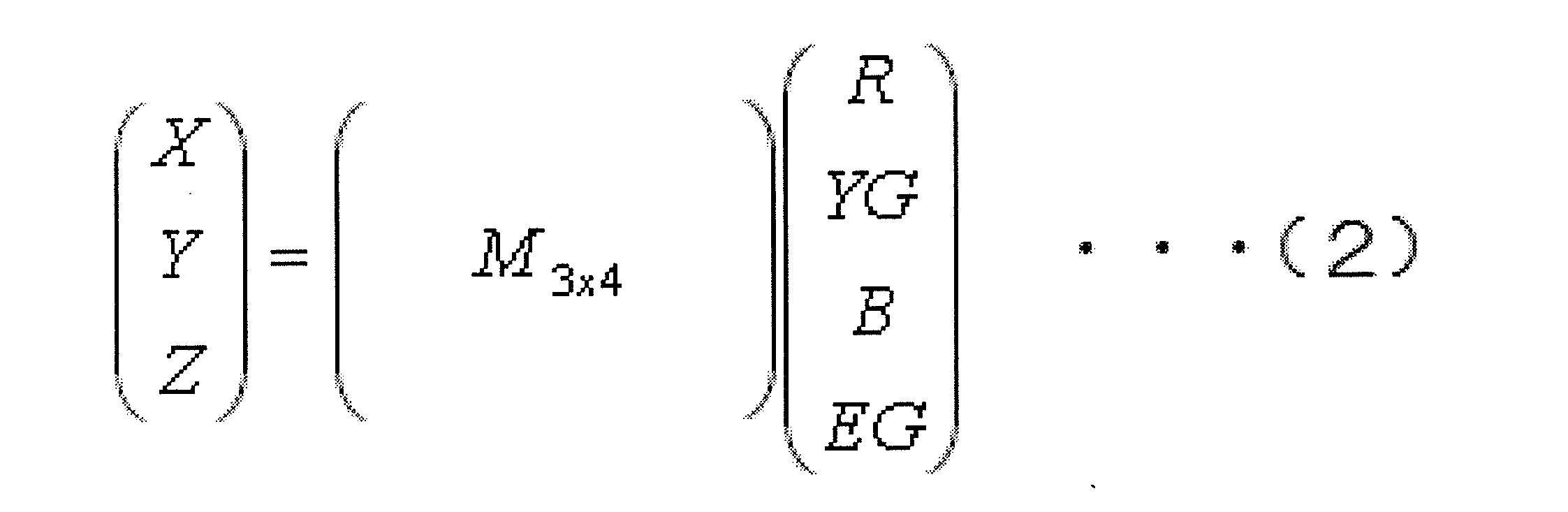
この場合は行列M3×4の逆行列を計算できないので、次式(3)を満たす4行3列の行列N4×3を求める必要がある。
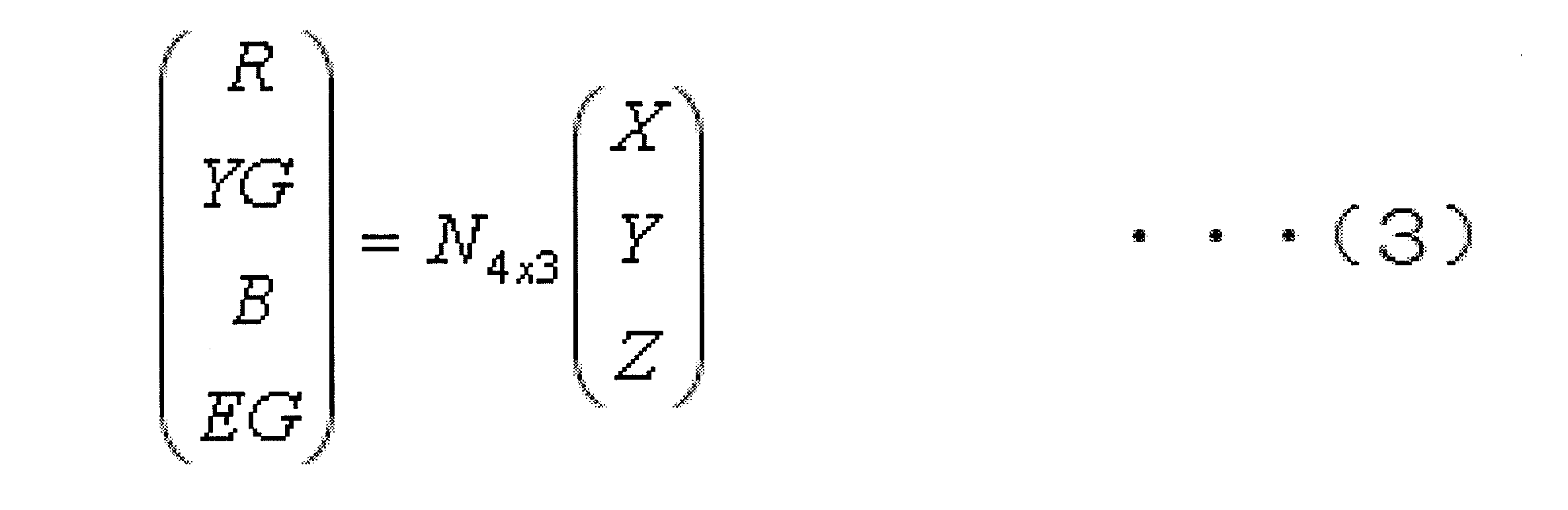
そして、行列N4×3を求めるに際し、次数を下げるために表示パネルの色再現域を複数に分割したうえで、分割した各領域のN4×3をそれぞれ計算することにより、4色成分への変換およびキャリブレーションを実現している。
このように、パネルのキャリブレーションを行う際、3原色ディスプレイに比べ増加した自由度により目標点に近づけるというプロセスが複雑となる。多原色ディスプレイをモニター、TV用途など含め幅広い用途で使用するためには、このキャリブレーションプロセスを効率よく行う指針が必要となる。特許文献3においては、領域分けをする(領域ごとに演算行列が入れ替わる)ことにより、キャリブレーションを効率良く行っている。しかしながら、この方法ではキャリブレーション時に境界をまたぐような調整が行われる場合に、演算行列が境界ごとに異なると、キャリブレーションが不連続で発散する可能性があるという問題がある。
本発明は、上記課題を鑑みてなされたものであり、その目的は、4原色ディスプレイにおけるキャリブレーションを効率良く行う手法を提供することにある。
本発明による液晶表示装置の製造方法は、複数の画素がそれぞれ異なる4色のサブ画素からなる液晶パネルを含む液晶表示装置の製造方法であって、前記4色の各原色表示の色度を測定する第一工程と、XYZ表色系の三刺激値X、Y、Zについて、青成分のZについて液晶パネルへの入力値と前記第一工程で測定された測定値との差ΔZを調整する第二工程と、前記第二工程の後に、青成分以外の色のXまたはYについて液晶パネルへの入力値と前記第一工程で測定された測定値との差ΔXまたはΔYを調整する第三工程とを有する。
本発明による手法はキャリブレーション時に領域分けをせず、全領域にわたって同様な処理を行うため、連続性を保ち安定したキャリブレーション結果を得ることができる。
本発明による液晶表示装置は、4原色ディスプレイにおけるキャリブレーションを可能にし、かつ効率良く行うことができる。
以下、図面を参照して、本発明による液晶表示装置の実施形態を説明する。ただし、本発明は、以下の実施形態に限定されるものではない。
以下、本発明による実施形態を説明する。図1に、液晶表示装置100およびキャリブレーションを行うシステムの模式図を示す。液晶表装置100は、液晶パネル10、バックライト(図示せず)および4原色変換回路30を備えている。液晶パネル10は複数の画素を有している。複数の画素は、複数の行および複数の列のマトリクス状に配列されている。各画素は4つのサブ画素によって規定されている。なお、このような液晶パネル10、液晶表示装置100はそれぞれ4原色パネル、4原色表示装置とも呼ばれる。
図2に、液晶パネル10における画素Pの模式図を示す。画素Pは、4以上のサブ画素を有している。4以上のサブ画素は互いに異なる色を表示する。画素Pはカラー表示画素とも呼ばれる。ここでは、画素Pは、赤サブ画素R、緑サブ画素G、青サブ画素Bおよび黄サブ画素Yeを有している。
なお、図2(a)では、赤サブ画素R、緑サブ画素G、青サブ画素Bおよび黄サブ画素Yeは行方向に沿って一列に示されているが、図2(b)のように赤サブ画素R、緑サブ画素G、青サブ画素Bおよび黄サブ画素Yeは2行2列のマトリクス状に配列されてもよい。また、図2では、赤サブ画素R、緑サブ画素G、青サブ画素Bおよび黄サブ画素Yeの面積は互いに等しく示されているが、赤サブ画素R、緑サブ画素G、青サブ画素Bおよび黄サブ画素Yeの面積は異なってもよい。赤サブ画素R、緑サブ画素G、青サブ画素Bおよび黄サブ画素Yeの面積の平均をサブ画素平均面積と呼ぶとすると、赤サブ画素Rの面積がサブ画素平均面積よりも大きいことにより、明度の高い赤色を充分に表現することができる。また、青サブ画素Bの面積がサブ画素平均面積よりも大きいことにより、バックライトの発光効率の低下を抑制できる。このため、赤サブ画素R、青サブ画素Bの面積は、緑サブ画素G、黄サブ画素Yeの面積よりも大きいことが好ましい。
4原色変換回路30は入力されるXYZまたはxvYCCなどの色情報を4原色信号R、G、B、Yeに変換し、液晶パネル10に供給する。なお、4色変換アルゴリズムは多くの手段が存在するが、本実施形態では、説明の簡略化のためXYZまたはxvYCCなどの色情報に対して忠実に色を再現できるようにR、G、B、Yeの組み合わせを選ぶ4色変換回路を考える。この4色変換により表示される画面の色度は、理想的には入力信号が想定しているXYZ値と一致するはずである。しかし実際の液晶パネルでは、パネル固有の問題により理想のXYZ値との差異が生じる。この差異を修正するためにキャリブレーションを行う必要がある。
本実施形態では、ある色度点X、Y、Zを実現するための4原色信号理論値(R、G、B、Ye)の組み合わせを表示する時の理論値と、実パネルでの測定値との誤差に対してキャリブレーションを行う。なお、目標点等の演算を理論値で行うため、計算に即したガンマ補正後のパネルでキャリブレーションを行うほうが好ましい。ガンマ補正を行うことにより、各原色が理論値に近い特性を示すようになる。他にもパネルの誤差の原因として考えられるのは、例えばサブ画素間のクロストークや低コントラストパネルで見られる低階調付近の彩度の低下などである。このような補正は、ガンマ補正の前、つまり4色変換部において補償(キャリブレーション)を行うことができる。
図3は4原色変換回路30の内部構成の一例を示している。4原色変換アルゴリズム回路1で入力された色情報を4原色信号R0、G0、B0、Ye0に変換した後に、ガンマ補正回路2でガンマ補正を行い、4原色信号Rout、Gout、Bout、Yeoutを出力している。
キャリブレーションは以下の方法で行う。4原色パネルに表示した色を色度測定器200で測定し、その測定結果をフィードバック回路300にフィードバックし、実際に使われた4色階調の理論値R0、B0、G0、Ye0との差をΔX、ΔY、ΔZとして認識し、青原色による調整や赤緑黄原色による調整を行い、調整後の4原色の組み合わせを4原色システムへフィードバックする。なお、任意に設定した色度ずれの許容範囲に収まらなかった場合は、再度同様な作業を繰り返す。
キャリブレーションのフローチャートを図4に示す。ステップ1で、まずパネルのガンマ値を合わせる。以下の演算は理論値で行うため、実パネルの色表示におけるガンマを補正しておく必要がある(例えばガンマ=2.2等)。ステップ2で、キャリブレーションを行う目標の4色の組み合わせを決定する。4色変換には様々なアルゴリズムが考えられるが、ここでは変換後の4色組み合わせから理論値を計算するため、変換アルゴリズムは指定しない。ステップ3で、三刺激値XYZを求める。理論値であるため、4原色の原色色度(下表1)を用い、補正されたガンマに則り4色で作られるXYZ値を求める。さらに、あらかじめ原色ごとにその各階調から微少量階調をずらした時のX、Y、Zの変化量を計算し、各色の挙動を定義する。ステップ4で、実際に4色階調を表示し、測定を行う。ステップ5で、目標値との誤差のうち、ΔZを最小化するような青原色の差分を求める。ステップ6で、残りのΔX、ΔYを最小化できるような赤緑黄原色の差分を求める。ステップ7で、結果の色度点と目標点の差を確認し、任意の色度ズレ許容範囲より大きければステップ3に戻る。
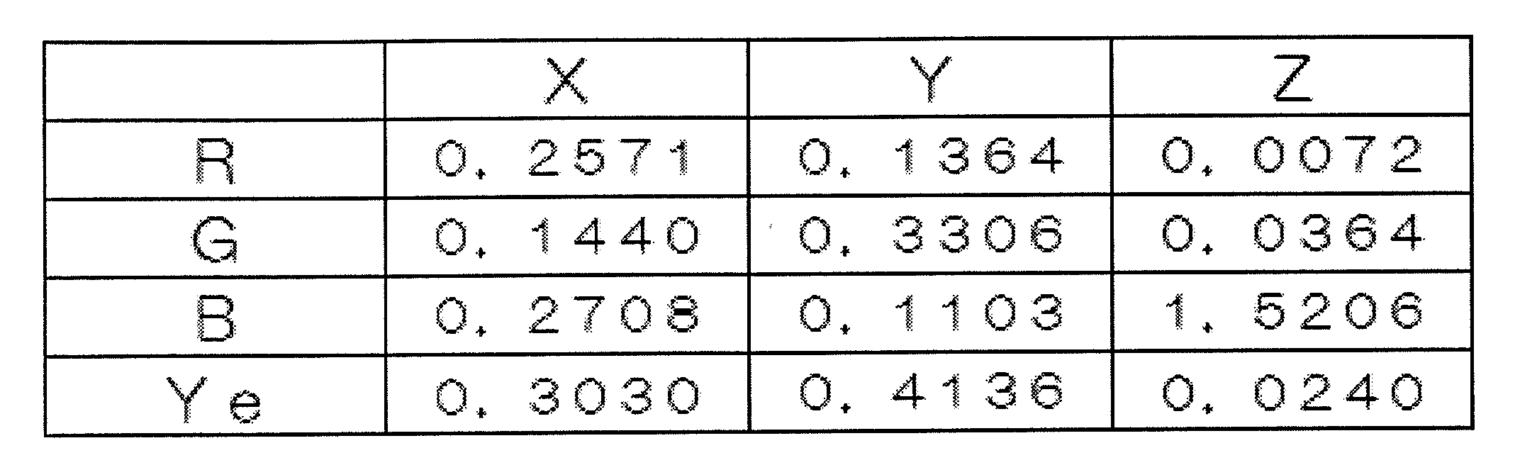
上記表1から分かるように、全体の構成要素に対してX成分は各原色とも似たような割合で構成されており、Y成分も緑画素や黄色画素に割合が偏って入るものの、オーダーとしてはそれほど大きな違いはない。ところが、青原色のZ成分に占める割合だけは桁違いに大きい。このことは、このパネルにおいて混色により表示される色のZ成分は、ほぼ青原色の影響であることを意味する。よって色調整において、Z成分の誤差は青原色を用いて効率的に調整を行うことができる。その後、残りの赤、緑、黄原色を用いてX、Y成分を調整する。本調整方法を用いることで4原色の自由度のうち1つを固定できるため、解が発散しにくく実用的な手法となり得る。
ステップ6およびステップ7における階調決定と色差判定についてさらに説明する。ステップ6で求められた変化量に応じて赤、緑、黄色画素を用いて調整を行う。そのまま一気に理想値に近づけるような調整を行うのは誤差の観点から好ましくない。特に誤差量が大きい場合は逆に理想値から離れてしまう可能性もある。そこで、1回の調整量の最大値Fを定義することで、数回に分けて理想値に近づけることにする。ステップ6で求められたR、G、Yeの変化量r、g、yeの中で最大絶対値をA_MAXとし、抑制係数C=A_MAX/Fとして導入する。ただし、A_MAX<FのときはC=1とする。この係数の導入により、変化量を抑制しつつ、階調変化の色バランス(キャリブレーションの方向)をある程度維持することができる。なお、最終的な変化量は、(r/C、g/C、ye/C)とする(ただし求める変化量は整数とする)。この変化量を反映し、最終的に得られたXYZに対し、目標値との色差を計算する。色差の許容値を設定しておき(例えば0.0003)、これを満たさない場合は試行を繰り返す。
以下、具体例を挙げて説明する。入力(目標色度点)階調を下表2のような4色の組み合わせとする。

このときの三刺激値XYZは、下表3のようになる。

この階調において、例えば赤原色の階調をR、原色のX成分をXRとするなら、ΔXR=[{(R+1)/255}2.2-(R/255)2.2]XRとして、1階調変化した時の原色点由来の三刺激値への影響を定義する。各色、XYZ成分それぞれについて微少変化量の計算を行う。その結果を下表4に示す。

パネルに表示した際の測定値は下表5のようになる。

ここで、ΔZを青原色で調整する。目標値と測定値のZ成分を比較すると、ΔZ/ΔZBで青原色の調整量が求まる。この場合は、下表6のようになり、Bの変化量がおよそマイナス3となることがわかる。

上記青原色の調整により変化したXYZを再計算し、もう一度目標点との差を定義したものを下表7に示す。

このΔX、ΔYを赤・緑・黄色原色の差分による変化をもとに数式で表すと以下の式(4)および式(5)のようになる。


ここでr、g、yeは赤緑黄の階調変化量である。
上記の式(4)および式(5)において、ΔX、ΔYを最小化するため、変化量{(ΔX)2+(ΔY)2}1/2を定義し、これを最小化するr、g、yeの組み合わせを選び出す。
上記プロセスで選ばれた変化量は下表8のようになる。

しかし、キャリブレーションプロセスにおいて、あまり大きな変化は好ましくない(上記において微小変化を前提に計算を行っている)。よって、一度に動かす最大の階調Fを定義する。本例ではF=5とする。上記R、G、Yeの変化量のうち、最大値の絶対値AMAXは15となっている。ここから抑制係数C=AMAX/Fを定義する。ただしAMAX<FのときはC=1とする。ここでは、C=15/5=3となる。上記変化量をこの抑制係数で除算した結果が下表9である。

この値を最終的な変化量として出力する。よって、試行1回目のキャリブレーションでは下表10のようになる。

この結果、三刺激値XYZは下表11のようになる。

初期状態の目標との色差Δu’v’=0.0085に対し、0.0066となり近づいていることが示された。色差の許容値を0.0003とすると未だ到達していないので、試行を繰り返す。4回の試行を行った結果、色差許容に収まった。
本実施例のキャリブレーションによる色度変化過程を図5に示す。試行1から4を行った後におけるそれぞれの表示階調RGBYeを下表12に示す。

試行1から4を行った後におけるそれぞれの三刺激値XYZおよび目標点との色差Δu’v’を下表13に示す。
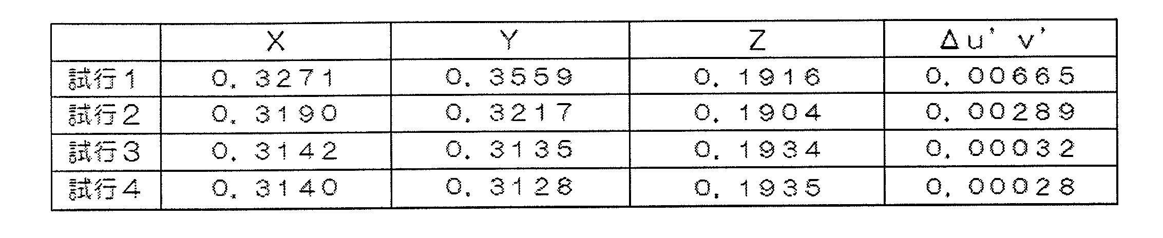
本実施例では、4原色の中で青原色だけがZに支配的な影響力をもつことに注目し、青原色を用いたZの調整を始めに行うことで調整の自由度を減らし、キャリブレーションを効率化することに成功したことが示された。本キャリブレーション法は、今後デザインや工業分野等へ4原色パネルの応用範囲が広がる際に有効な調整手段となる。
本発明による液晶表示装置は、広い色再現範囲の表示を低消費電力で行うことができる。
1 4原色変換アルゴリズム回路
2 ガンマ補正回路
10 液晶パネル
30 4原色変換回路
100 液晶表示装置
200 色度測定器
300 フィードバック回路
2 ガンマ補正回路
10 液晶パネル
30 4原色変換回路
100 液晶表示装置
200 色度測定器
300 フィードバック回路
Claims (1)
- 複数の画素がそれぞれ異なる4色のサブ画素からなる液晶パネルを含む液晶表示装置の製造方法において、
前記4色の各原色表示の色度を測定する第一工程と、
XYZ表色系の三刺激値X、Y、Zについて、青成分のZについて液晶パネルへの入力値と前記第一工程で測定された測定値との差ΔZを調整する第二工程と、
前記第二工程の後に、青成分以外の色のXまたはYについて液晶パネルへの入力値と前記第一工程で測定された測定値との差ΔXまたはΔYを調整する第三工程と、
を有することを特徴とする液晶表示装置の製造方法。
Applications Claiming Priority (2)
| Application Number | Priority Date | Filing Date | Title |
|---|---|---|---|
| JP2010-268099 | 2010-12-01 | ||
| JP2010268099A JP2014038117A (ja) | 2010-12-01 | 2010-12-01 | 液晶表示装置 |
Publications (1)
| Publication Number | Publication Date |
|---|---|
| WO2012073864A1 true WO2012073864A1 (ja) | 2012-06-07 |
Family
ID=46171796
Family Applications (1)
| Application Number | Title | Priority Date | Filing Date |
|---|---|---|---|
| PCT/JP2011/077324 Ceased WO2012073864A1 (ja) | 2010-12-01 | 2011-11-28 | 液晶表示装置 |
Country Status (2)
| Country | Link |
|---|---|
| JP (1) | JP2014038117A (ja) |
| WO (1) | WO2012073864A1 (ja) |
Cited By (1)
| Publication number | Priority date | Publication date | Assignee | Title |
|---|---|---|---|---|
| WO2014013983A1 (ja) * | 2012-07-20 | 2014-01-23 | シャープ株式会社 | 表示装置 |
Citations (5)
| Publication number | Priority date | Publication date | Assignee | Title |
|---|---|---|---|---|
| JP2005128254A (ja) * | 2003-10-23 | 2005-05-19 | Nanao Corp | 表示特性較正方法、表示特性較正装置及びコンピュータプログラム |
| JP2005328386A (ja) * | 2004-05-14 | 2005-11-24 | Sharp Corp | ホワイトバランス補正回路の設定システム及び方法、該システムに使用するlsi回路、及び液晶テレビ |
| JP2007241120A (ja) * | 2006-03-10 | 2007-09-20 | Casio Hitachi Mobile Communications Co Ltd | 画像処理装置、画像処理方法、及び、プログラム |
| JP2010217516A (ja) * | 2009-03-17 | 2010-09-30 | Sony Corp | 画像表示装置 |
| WO2011083808A1 (ja) * | 2010-01-07 | 2011-07-14 | シャープ株式会社 | 液晶表示装置および信号変換回路 |
-
2010
- 2010-12-01 JP JP2010268099A patent/JP2014038117A/ja active Pending
-
2011
- 2011-11-28 WO PCT/JP2011/077324 patent/WO2012073864A1/ja not_active Ceased
Patent Citations (5)
| Publication number | Priority date | Publication date | Assignee | Title |
|---|---|---|---|---|
| JP2005128254A (ja) * | 2003-10-23 | 2005-05-19 | Nanao Corp | 表示特性較正方法、表示特性較正装置及びコンピュータプログラム |
| JP2005328386A (ja) * | 2004-05-14 | 2005-11-24 | Sharp Corp | ホワイトバランス補正回路の設定システム及び方法、該システムに使用するlsi回路、及び液晶テレビ |
| JP2007241120A (ja) * | 2006-03-10 | 2007-09-20 | Casio Hitachi Mobile Communications Co Ltd | 画像処理装置、画像処理方法、及び、プログラム |
| JP2010217516A (ja) * | 2009-03-17 | 2010-09-30 | Sony Corp | 画像表示装置 |
| WO2011083808A1 (ja) * | 2010-01-07 | 2011-07-14 | シャープ株式会社 | 液晶表示装置および信号変換回路 |
Cited By (3)
| Publication number | Priority date | Publication date | Assignee | Title |
|---|---|---|---|---|
| WO2014013983A1 (ja) * | 2012-07-20 | 2014-01-23 | シャープ株式会社 | 表示装置 |
| JP2014039246A (ja) * | 2012-07-20 | 2014-02-27 | Sharp Corp | 表示装置 |
| CN104471922A (zh) * | 2012-07-20 | 2015-03-25 | 夏普株式会社 | 显示装置 |
Also Published As
| Publication number | Publication date |
|---|---|
| JP2014038117A (ja) | 2014-02-27 |
Similar Documents
| Publication | Publication Date | Title |
|---|---|---|
| US9318075B2 (en) | Image driving using color-compensated image data that has been color-scheme converted | |
| US7301543B2 (en) | Systems and methods for selecting a white point for image displays | |
| CN101419771B (zh) | 图像显示设备以及用于该图像显示设备的图像显示方法 | |
| US9886932B2 (en) | Multi-primary color display device | |
| US9055283B2 (en) | Methods for display uniform gray tracking and gamma calibration | |
| CN101923828B (zh) | 对显示器中的颜色偏移的补偿技术 | |
| WO2012096345A1 (ja) | 表示装置の階調補正方法、および、表示装置の製造方法 | |
| KR101134269B1 (ko) | 디스플레이 장치 및 디스플레이 장치의 휘도 조정 방법 | |
| US10347198B2 (en) | Image displaying methods and display devices | |
| CN106297728B (zh) | 图像处理设备和图像处理方法 | |
| JP2014122997A (ja) | 表示装置、画像処理装置、表示方法、および電子機器 | |
| WO2005111980A1 (ja) | 表示装置 | |
| KR20150022235A (ko) | 색 보상 장치와 이를 포함하는 표시 장치, 및 색 보상 방법 | |
| US9601048B2 (en) | Image processing device and electronic apparatus | |
| KR20110081546A (ko) | 신호 처리 장치 및 신호 처리 방법 | |
| WO2019054178A1 (ja) | 表示装置、及び信号処理装置 | |
| WO2012005170A1 (ja) | 多原色液晶表示装置 | |
| WO2019155760A1 (ja) | 画像処理装置、表示装置、画像処理方法 | |
| KR20180052836A (ko) | 표시 장치 및 그 구동 방법 | |
| KR20160041923A (ko) | 신호 생성 장치, 신호 생성 프로그램, 신호 생성 방법, 및, 화상 표시 장치 | |
| WO2012073864A1 (ja) | 液晶表示装置 | |
| US9177512B2 (en) | Display device | |
| JP2017083606A (ja) | 表示信号生成装置 | |
| JP2016208327A (ja) | 表示装置、ホワイトバランス調整方法およびテレビジョン装置 | |
| KR101046678B1 (ko) | 디스플레이 및 그 구동방법 |
Legal Events
| Date | Code | Title | Description |
|---|---|---|---|
| 121 | Ep: the epo has been informed by wipo that ep was designated in this application |
Ref document number: 11845973 Country of ref document: EP Kind code of ref document: A1 |
|
| NENP | Non-entry into the national phase |
Ref country code: DE |
|
| 122 | Ep: pct application non-entry in european phase |
Ref document number: 11845973 Country of ref document: EP Kind code of ref document: A1 |
|
| NENP | Non-entry into the national phase |
Ref country code: JP |