WO2012073748A1 - ラミネート外装電池及びその製造方法 - Google Patents
ラミネート外装電池及びその製造方法 Download PDFInfo
- Publication number
- WO2012073748A1 WO2012073748A1 PCT/JP2011/076852 JP2011076852W WO2012073748A1 WO 2012073748 A1 WO2012073748 A1 WO 2012073748A1 JP 2011076852 W JP2011076852 W JP 2011076852W WO 2012073748 A1 WO2012073748 A1 WO 2012073748A1
- Authority
- WO
- WIPO (PCT)
- Prior art keywords
- battery
- metal laminate
- sealing
- metal
- laminate sheets
- Prior art date
- Legal status (The legal status is an assumption and is not a legal conclusion. Google has not performed a legal analysis and makes no representation as to the accuracy of the status listed.)
- Ceased
Links
Images

Classifications
-
- H—ELECTRICITY
- H01—ELECTRIC ELEMENTS
- H01M—PROCESSES OR MEANS, e.g. BATTERIES, FOR THE DIRECT CONVERSION OF CHEMICAL ENERGY INTO ELECTRICAL ENERGY
- H01M50/00—Constructional details or processes of manufacture of the non-active parts of electrochemical cells other than fuel cells, e.g. hybrid cells
- H01M50/10—Primary casings; Jackets or wrappings
- H01M50/116—Primary casings; Jackets or wrappings characterised by the material
- H01M50/124—Primary casings; Jackets or wrappings characterised by the material having a layered structure
-
- H—ELECTRICITY
- H01—ELECTRIC ELEMENTS
- H01M—PROCESSES OR MEANS, e.g. BATTERIES, FOR THE DIRECT CONVERSION OF CHEMICAL ENERGY INTO ELECTRICAL ENERGY
- H01M50/00—Constructional details or processes of manufacture of the non-active parts of electrochemical cells other than fuel cells, e.g. hybrid cells
- H01M50/10—Primary casings; Jackets or wrappings
- H01M50/183—Sealing members
- H01M50/186—Sealing members characterised by the disposition of the sealing members
-
- H—ELECTRICITY
- H01—ELECTRIC ELEMENTS
- H01M—PROCESSES OR MEANS, e.g. BATTERIES, FOR THE DIRECT CONVERSION OF CHEMICAL ENERGY INTO ELECTRICAL ENERGY
- H01M50/00—Constructional details or processes of manufacture of the non-active parts of electrochemical cells other than fuel cells, e.g. hybrid cells
- H01M50/10—Primary casings; Jackets or wrappings
- H01M50/102—Primary casings; Jackets or wrappings characterised by their shape or physical structure
- H01M50/105—Pouches or flexible bags
-
- H—ELECTRICITY
- H01—ELECTRIC ELEMENTS
- H01M—PROCESSES OR MEANS, e.g. BATTERIES, FOR THE DIRECT CONVERSION OF CHEMICAL ENERGY INTO ELECTRICAL ENERGY
- H01M50/00—Constructional details or processes of manufacture of the non-active parts of electrochemical cells other than fuel cells, e.g. hybrid cells
- H01M50/10—Primary casings; Jackets or wrappings
- H01M50/116—Primary casings; Jackets or wrappings characterised by the material
- H01M50/117—Inorganic material
- H01M50/119—Metals
-
- H—ELECTRICITY
- H01—ELECTRIC ELEMENTS
- H01M—PROCESSES OR MEANS, e.g. BATTERIES, FOR THE DIRECT CONVERSION OF CHEMICAL ENERGY INTO ELECTRICAL ENERGY
- H01M50/00—Constructional details or processes of manufacture of the non-active parts of electrochemical cells other than fuel cells, e.g. hybrid cells
- H01M50/10—Primary casings; Jackets or wrappings
- H01M50/116—Primary casings; Jackets or wrappings characterised by the material
- H01M50/121—Organic material
-
- H—ELECTRICITY
- H01—ELECTRIC ELEMENTS
- H01M—PROCESSES OR MEANS, e.g. BATTERIES, FOR THE DIRECT CONVERSION OF CHEMICAL ENERGY INTO ELECTRICAL ENERGY
- H01M50/00—Constructional details or processes of manufacture of the non-active parts of electrochemical cells other than fuel cells, e.g. hybrid cells
- H01M50/10—Primary casings; Jackets or wrappings
- H01M50/116—Primary casings; Jackets or wrappings characterised by the material
- H01M50/124—Primary casings; Jackets or wrappings characterised by the material having a layered structure
- H01M50/126—Primary casings; Jackets or wrappings characterised by the material having a layered structure comprising three or more layers
- H01M50/129—Primary casings; Jackets or wrappings characterised by the material having a layered structure comprising three or more layers with two or more layers of only organic material
-
- H—ELECTRICITY
- H01—ELECTRIC ELEMENTS
- H01M—PROCESSES OR MEANS, e.g. BATTERIES, FOR THE DIRECT CONVERSION OF CHEMICAL ENERGY INTO ELECTRICAL ENERGY
- H01M50/00—Constructional details or processes of manufacture of the non-active parts of electrochemical cells other than fuel cells, e.g. hybrid cells
- H01M50/10—Primary casings; Jackets or wrappings
- H01M50/183—Sealing members
- H01M50/19—Sealing members characterised by the material
- H01M50/193—Organic material
-
- H—ELECTRICITY
- H01—ELECTRIC ELEMENTS
- H01M—PROCESSES OR MEANS, e.g. BATTERIES, FOR THE DIRECT CONVERSION OF CHEMICAL ENERGY INTO ELECTRICAL ENERGY
- H01M50/00—Constructional details or processes of manufacture of the non-active parts of electrochemical cells other than fuel cells, e.g. hybrid cells
- H01M50/10—Primary casings; Jackets or wrappings
- H01M50/102—Primary casings; Jackets or wrappings characterised by their shape or physical structure
- H01M50/103—Primary casings; Jackets or wrappings characterised by their shape or physical structure prismatic or rectangular
-
- Y—GENERAL TAGGING OF NEW TECHNOLOGICAL DEVELOPMENTS; GENERAL TAGGING OF CROSS-SECTIONAL TECHNOLOGIES SPANNING OVER SEVERAL SECTIONS OF THE IPC; TECHNICAL SUBJECTS COVERED BY FORMER USPC CROSS-REFERENCE ART COLLECTIONS [XRACs] AND DIGESTS
- Y02—TECHNOLOGIES OR APPLICATIONS FOR MITIGATION OR ADAPTATION AGAINST CLIMATE CHANGE
- Y02E—REDUCTION OF GREENHOUSE GAS [GHG] EMISSIONS, RELATED TO ENERGY GENERATION, TRANSMISSION OR DISTRIBUTION
- Y02E60/00—Enabling technologies; Technologies with a potential or indirect contribution to GHG emissions mitigation
- Y02E60/10—Energy storage using batteries
Definitions
- the present invention relates to a battery using a metal laminate sheet in which a metal layer and a resin layer are laminated as an exterior body.
- laminated exterior battery batteries having a high energy density and light weight and using a metal laminate sheet in which a metal layer and a resin layer are laminated as an exterior body. It is used in many types of mobile devices.
- a laminated battery is cup-formed by punching a part of a metal laminate sheet, and an electrode body composed of a positive electrode, a negative electrode, and a separator is accommodated in the cup-molded part, and the opening of the cup-formed part is closed with the metal laminate sheet.
- the outer peripheral part of the sheet around the cup forming part is sealed (hereinafter referred to as “sealing part”).
- the laminated battery has a problem that when moisture enters the outer package, gas is generated due to a side reaction of moisture inside the battery, and the battery swells. Therefore, in order to prevent the problem of battery swelling due to moisture mixing, it is usually necessary to make the width of the sealing portion sufficiently long so that moisture does not permeate.
- the present invention solves the above-described problems, and provides a laminate-cased battery having a sealing part reliability that does not change from the width of a normal sealing part even if the width of the sealing part is shortened, and a method for manufacturing the same. With the goal.
- the laminated battery of the present invention is An electrode body is housed in an internal space formed between the first and second metal laminate sheets formed by laminating a metal layer and a resin layer, and the outer edges of the first and second metal laminate sheets are In the laminated exterior battery in which the resin layers are sealed by heat welding to form a sealed portion, A seal having the same or lower melting point than that of the resin layer from between the first and second metal laminate sheets of the sealing portion to an internal space formed by the first and second metal laminate sheets. A stop member is arranged, The sealing member is welded to the resin layers of the first and second metal laminate sheets.
- the method for producing a laminated battery according to the present invention includes: An electrode body is housed in an internal space formed between the first and second metal laminate sheets formed by laminating the metal layer and the resin layer, and between the outer edges of the first and second metal laminate sheets.
- a sealing member having the same or lower melting point than that of the resin layer is disposed and laminated, and the laminated portions are thermally welded and sealed, whereby the molten sealing member is the first and It flows out to the internal space formed with a 2nd metal laminate sheet, It is characterized by the above-mentioned.
- the melting point of the sealing portion at the outer edge of the first and second metal laminate sheets is higher than that of the resin layers of the first and second metal laminate sheets.
- the same or lower sealing member is disposed from between the first and second metal laminate sheets of the sealing portion to the internal space, that is, across the gap formed by the sealing portion and the electrode body. The sealing member melts before the resin layer of the metal laminate sheet when the sealing portion is thermally welded, and flows into the gap formed by the sealing portion of the metal laminate sheet and the electrode body. The resin layers of the first and second metal laminate sheets are welded.
- the sealing part of a metal laminate sheet is integrated with the fusion
- fusing point is the same or low compared with the resin layer of a 1st and 2nd metal laminate sheet in the sealing part of a 1st and 2nd metal laminate sheet Sealing members are arranged and stacked, and the stacked portions are thermally welded and sealed.
- the sealing member is caused to flow into the internal space formed by the first and second metal laminate sheets, that is, the gap formed by the sealing portion and the electrode body, thereby substantially It becomes possible to manufacture a laminate-coated battery having a wide width and high sealing reliability.
- the sealing member When the sealing member is disposed between the first and second metal laminate sheets, the sealing member is shifted from the sealing portion to the internal space side of the battery, that is, the electrode body side, and the sealing portion and the electrode Arrange it so that it covers the gap formed by the body.
- the sealing member By disposing the sealing member as described above, it is possible to make the sealing member melted more reliably in the gap formed by the sealing portion and the electrode body.
- Partial cross-sectional view of the battery of the present invention before producing a sealed part Partial sectional view of the sealed portion of the battery of the present invention
- Partial sectional view of the comparative battery before the sealing part is produced Partial sectional view of the sealing part of the comparative battery
- Example 1 Production of negative electrode A negative electrode active material made of artificial graphite having a volume average particle diameter of 20 ⁇ m, a finalizer made of styrene butadiene rubber, and a thickener made of carboxymethylcellulose were mixed at a ratio of 98: 1: 1 (mass ratio). Then, water was added thereto to prepare a negative electrode active material slurry. Next, this negative electrode active material slurry was applied to both surfaces of a negative electrode core made of a copper foil having a width of 30.0 mm and a length of 715 mm using a die coater or a doctor blade. Further, the negative electrode core body coated with the negative electrode active material slurry is passed through a dryer to remove moisture, and a dry electrode plate is produced. Thereafter, the dry electrode plate is 0.14 mm in thickness by a roll press. It rolled so that it might become, and the negative electrode was produced.
- a positive electrode active material made of lithium cobaltate (LiCoO 2 ), a carbon-based conductive agent such as acetylene black or graphite, and a binder made of polyvinylidene fluoride (PVDF) were mixed in 90: 5: 5 ( (Mass ratio), and these were dissolved in an organic solvent composed of N-methyl-2-pyrrolidone to prepare a positive electrode active material slurry.
- this positive electrode active material slurry was applied to both surfaces of a positive electrode core made of an aluminum foil having a width of 28.5 mm and a length of 725 mm using a die coater or a doctor blade.
- the positive electrode core body coated with this positive electrode active material slurry is passed through a dryer to remove moisture, and a dry electrode plate is produced. Thereafter, the dry electrode plate is formed to a thickness of 0.16 mm by a roll press. It rolled so that it might become, and the positive electrode was produced.
- a negative electrode current collector tab made of nickel was connected to the negative electrode core body, and a positive electrode current collector tab made of aluminum was connected to the positive electrode core body.
- the negative electrode current collection tab and the positive electrode current collection tab were each provided with a tab film made of polypropylene modified with carboxylic acid at a portion overlapping with the sealing portion of the metal laminate sheet. With this tab film, the positive and negative electrode current collecting tabs and the sealing portion can be firmly welded to each other, and contact between the current collecting tabs and the metal layer of the metal laminate sheet can be prevented.
- a non-aqueous electrolyte was prepared by preparing a solution of LiPF 6 dissolved in an aqueous solvent at a rate of 1.0 M (mol / liter) as an electrolyte salt.
- a laminate sheet was used as an exterior body.
- the metal layer and the nylon layer are bonded by a dry laminate adhesive layer having a thickness of 5 ⁇ m, and the metal layer and the polypropylene layer are bonded by a carboxylic acid-modified polypropylene layer having a thickness of 5 ⁇ m.
- the nylon layer was placed outside the battery.
- the exterior body is recessed in the central region of the first metal laminate sheet to form a cup forming portion that houses the electrode body.
- the electrode body was housed in this molded part, and after the electrolyte solution was injected, it was bent at a predetermined position, and the bent part was used as the second metal laminate sheet.
- the polypropylene resin layers inside the first and second metal laminate sheets are welded together by thermal welding to form a sealing portion to form a three-side sealing structure.
- variety of each sealing part was 2.8 mm.
- the sealing member is configured from the space between the first and second metal laminate sheets of the sealing portion to the internal space formed by the first and second metal laminate sheets, that is, the sealing portion and the electrode body. It is arranged over the gap. Therefore, the sealing member sandwiched between the first and second metal laminate sheets is melted by heating when the sealing portion is formed, and the melt is composed of the sealing portion and the electrode body.
- the sealing member that has flowed out into the gap and melted is substantially integrated. This substantially increases the sealing width. In this manner, a laminate-cased battery was produced and designated as the present invention battery A1.
- the product made from polypropylene was used as the sealing member, acid-modified polypropylene, acid-modified polyethylene, acid-modified polyolefin resin, propylene resin (homotype, ethylene / propylene copolymer, ethylene / propylene / butene copolymer) ), Ethylene resin (low density polyethylene, copolymer of ethylene and butene, copolymer of ethylene and acrylic acid or methacrylic acid derivative, copolymer of ethylene and vinyl acetate, metal ion content
- a simple substance or a blend of polyethylene or polypropylene grafted with polyethylene and an unsaturated carboxylic acid may be used.
- a sealing member having the same or low melting point as compared with the inner resin of the metal laminate sheet is preferable.
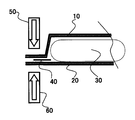
- FIG. 1 shows a partial cross-sectional view of the battery A1 of the present invention before producing a sealed portion
- FIG. 10 is a first metal laminate sheet
- 20 is a second metal laminate sheet
- 30 is an electrode body
- 40 is a polypropylene sealing member
- 50 is an upper sealing mold
- 60 is a lower sealing mold.
- the electrode body is housed in the cup molding portion formed in the first metal laminate sheet, the cup molding portion is closed with the second metal laminate sheet, and the first and second metal laminates
- the sealing portion (2.8 mm width) provided on the outer edge of the sheet is sealed while being pressurized and heated with the upper sealing mold 50 and the lower sealing mold 60.
- each of the upper sealing mold 50 and the lower sealing mold 60 has an embedded heater.
- melted sealing member can be united, and a new sealing part can be comprised, and it can be set as the sealing width longer than usual. Accordingly, since the sealed distance is increased by the amount of the sealing member sandwiched, the sealing reliability is remarkably improved.
- the melted sealing member can compensate for the shortened portion. Reliability can be obtained.
- the same sheet is folded to obtain the first metal laminate sheet and the second metal laminate sheet, so that the sealing portion is provided in three places.
- the first metal laminate sheet and the second metal laminate sheet are provided.
- the metal laminate sheet may be a separate member. In this case, there are four sealing portions.
- Example 2 A laminated exterior battery was produced in the same manner as in Example 1 except that the width of the sealing portion was 2.0 mm. This battery is referred to as the present invention battery A2.
- Example 3 A laminated exterior battery was produced in the same manner as in Example 1 except that the width of the sealing portion was 1.5 mm. This battery is referred to as “invention battery A3”.
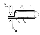
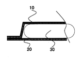
- Comparative Example 1 As shown in FIGS. 3 and 4, a laminated exterior battery was produced in the same manner as in Example 1 except that the metal laminate sheet was sealed without being sandwiched between members. This battery is referred to as a comparative battery X1.
- Battery swelling rate (%) ((Battery thickness after storage of each day ⁇ Battery thickness before storage) / Battery thickness before storage) ⁇ 100
- the battery swelling rate (%) is an average value of 3 cells of each battery.
- FIG. 5 shows the relationship between the number of days left and the battery expansion rate (%).
- the battery expansion ratios of the batteries A1 to A3 of the present invention on the 10th day are 1.1% to 3.2%, and the comparative battery X1 is 4.3% there were.
- the battery swelling ratios on the 20th day of the batteries A1 to A3 of the present invention were 3.9% to 11.6%, and the comparative battery X1 was 15.5%. From this result, it can be seen that the batteries A1 to A3 of the present invention have a very low battery expansion rate compared to the comparative battery X1.
- the batteries A1 to A3 of the present invention have better sealing reliability than the comparative battery X1 even if the width of the sealing portion is shortened.
- the reason for this is that a sealing member having the same or lower melting point than the inner resin of the metal laminate sheet is sandwiched between the first and second metal laminate sheets in the sealing portion, so that the sealing portion is thermally welded.
- the sealing member also melted out and flowed into the gap formed by the sealing portion and the electrode body to form a sealing structure integrated with the sealing portion. It is considered that such a sealing structure can prevent moisture from permeating into the battery and suppress the swelling of the battery.
- examples of the negative electrode active material that can be used in the present invention include carbon raw materials such as graphite, non-graphitizable carbon, and graphitizable carbon, titanium oxides such as LiTiO 2 and TiO 2 , and semimetals such as silicon and tin. Examples thereof include elements, Sn—Co alloys, and the like.
- Nonaqueous solvents that can be used in the present invention include cyclic carbonates such as ethylene carbonate (EC), propylene carbonate (PC), butylene carbonate (BC), fluorinated cyclic carbonates, ⁇ -butyllactone ( BL), cyclic carboxylic acid esters such as ⁇ -valerolactone (VL), dimethyl carbonate (DMC), ethyl methyl carbonate (EMC), diethyl carbonate (DEC), methyl propyl carbonate (MPC), dibutyl carbonate (DNBC), etc.
- cyclic carbonates such as ethylene carbonate (EC), propylene carbonate (PC), butylene carbonate (BC), fluorinated cyclic carbonates, ⁇ -butyllactone ( BL), cyclic carboxylic acid esters such as ⁇ -valerolactone (VL), dimethyl carbonate (DMC), ethyl methyl carbonate (EMC), diethyl carbonate (DEC), methyl
- Chain carbonate esters chain carboxylates such as methyl pivalate, ethyl pivalate, methyl isobutyrate, methyl propionate, amide compounds such as N, N′-dimethylformamide, N-methyloxazolidinone, sulfolane, etc.
- Sulfur compounds such as ambient temperature molten salt such as tetrafluoroboric acid 1-ethyl-3-methylimidazolium can be exemplified. It is desirable to use a mixture of two or more of these.
- EC, PC, chain carbonate ester, and tertiary carboxylic acid ester are particularly preferable.
- the electrolyte salt to be dissolved in the nonaqueous solvent used in the present invention examples include LiPF 6, LiBF 4, LiCF 3 SO 3, LiN (CF 3 SO 2) 2, LiN (C 2 F 5 SO 2) 2, LiN (CF 3 SO 2) (C 4 F 9 SO 2), LiC (CF 3 SO 2) 3, LiC (C 2 F 5 SO 2) 3, LiAsF 6, LiClO 4, Examples include Li 2 B 10 Cl 10 , Li 2 B 12 Cl 12 , and mixtures thereof. Among these, LiPF 6 (lithium hexafluorophosphate) is particularly preferable.
- the amount of electrolyte salt dissolved in the non-aqueous solvent is preferably 0.5 to 2.0 mol / L.
- vinylene carbonate VC
- vinyl ethyl carbonate VEC
- succinic anhydride SUCAH
- maleic anhydride MAAH
- Glycolic anhydride ethylene sulfite (ES), divinyl sulfone (VS), vinyl acetate (VA), vinyl pivalate (VP), catechol carbonate, biphenyl (BP) and the like
- ES ethylene sulfite
- VS divinyl sulfone
- VA vinyl pivalate
- catechol carbonate BP
- BP biphenyl
Landscapes
- Chemical & Material Sciences (AREA)
- Chemical Kinetics & Catalysis (AREA)
- Electrochemistry (AREA)
- General Chemical & Material Sciences (AREA)
- Inorganic Chemistry (AREA)
- Sealing Battery Cases Or Jackets (AREA)
Abstract
【課題】封止部の幅を短くしても、従来と変わらない封止信頼性を有するラミネート外装電池を提供する。 【解決手段】本発明のラミネート外装電地は、金属層と樹脂層とを積層してなる第1及び第2の金属ラミネートシートとの間に形成される内部空間に電極体を収納し、前記第1及び第2の金属ラミネートシートの外縁の前記樹脂層同士を熱溶着により封止して封止部を形成したラミネート外装電池において、前記封止部の前記第1と第2の金属ラミネートシートの間から、前記第1及び第2の金属ラミネートシートで形成される内部空間にかけて、前記樹脂層と比較して融点が同じもしくは低い封止部材が配置され、当該封止部材が、前記第1及び第2の金属ラミネートシートの前記樹脂層と溶着していることを特徴とする。
Description
本発明は、金属層と樹脂層とが積層される金属ラミネートシートを外装体として用いた電池に関するものである。
近年、携帯電話、携帯型パーソナルコンピュータ、携帯型音楽プレーヤー等の携帯機器の普及に伴い、これらの駆動電源として、リチウムイオン二次電池等が広く利用されている。特に、高いエネルギー密度を有し、且つ軽量であり、金属層と樹脂層とが積層される金属ラミネートシートを外装体として用いた電池(以下、「ラミネート外装電池」と記載する。)は、これらの携帯機器の多くの機種に採用されている。
ラミネート外装電池は、金属ラミネートシートの一部分にパンチ加工を施すことによってカップ成形し、そのカップ成形部内に正極、負極、セパレータからなる電極体を収納し、金属ラミネートシートでカップ成形部の開口を塞ぎ、カップ成形部の周囲のシート外周部を封止(以下、「封止部」と記載する。)することによって構成されている。
ここで、ラミネート外装電池は、外装体内に水分が混入すると、電池内部で水分の副反応によるガスが発生し、電池が膨れるという問題があった。そこで、水分の混入による電池の膨れという問題を防止するため、通常、封止部の幅を水分が透過しないように十分に長くする必要があった。
また、ラミネート外装電池は、電池を所定のサイズ幅にして電子機器に組み込むことを目的として、電極体の両サイドにおける封止部を電極体の厚み方向に折り曲げることが一般的に行われている。
しかしながら、上述したように、ラミネート外装電池の内部に水分を混入させないために、封止部の幅を長くすると、この封止部を電極体の厚み方向に折り曲げる際、電極体の厚み以上になり、封止部を何重にも折り返す必要があった。そして、封止部を何重にも折り曲げると折り曲げた箇所が嵩張り、電池を所定のサイズ幅にすることが困難になるという課題があった。
本発明は、上記課題を解決し、封止部の幅を短くしても、通常の封止部の幅と変わらない封止部の信頼性を有するラミネート外装電池及びその製造方法を提供することを目的とする。
上記目的を達成するため、本発明のラミネート外装電池は、
金属層と樹脂層とを積層してなる第1及び第2の金属ラミネートシートとの間に形成される内部空間に電極体を収納し、前記第1及び第2の金属ラミネートシートの外縁の前記樹脂層同士を熱溶着により封止して封止部を形成したラミネート外装電池において、
前記封止部の前記第1と第2の金属ラミネートシートの間から、前記第1及び第2の金属ラミネートシートで形成される内部空間にかけて、前記樹脂層と比較して融点が同じもしくは低い封止部材が配置され、
当該封止部材が、前記第1及び第2の金属ラミネートシートの前記樹脂層と溶着していることを特徴とする。
金属層と樹脂層とを積層してなる第1及び第2の金属ラミネートシートとの間に形成される内部空間に電極体を収納し、前記第1及び第2の金属ラミネートシートの外縁の前記樹脂層同士を熱溶着により封止して封止部を形成したラミネート外装電池において、
前記封止部の前記第1と第2の金属ラミネートシートの間から、前記第1及び第2の金属ラミネートシートで形成される内部空間にかけて、前記樹脂層と比較して融点が同じもしくは低い封止部材が配置され、
当該封止部材が、前記第1及び第2の金属ラミネートシートの前記樹脂層と溶着していることを特徴とする。
また、本発明のラミネート外装電池の製造方法は、
金属層と樹脂層とを積層してなる第1及び第2の金属ラミネートシートとの間に形成される内部空間に電極体を収納し、前記第1及び第2の金属ラミネートシートの外縁の間に、前記樹脂層と比較して融点が同じもしくは低い封止部材を配置して積層し、これら積層した部分を熱溶着して封止することにより、溶融した前記封止部材を前記第1及び第2の金属ラミネートシートで形成される内部空間に流れ出させることを特徴とする。
金属層と樹脂層とを積層してなる第1及び第2の金属ラミネートシートとの間に形成される内部空間に電極体を収納し、前記第1及び第2の金属ラミネートシートの外縁の間に、前記樹脂層と比較して融点が同じもしくは低い封止部材を配置して積層し、これら積層した部分を熱溶着して封止することにより、溶融した前記封止部材を前記第1及び第2の金属ラミネートシートで形成される内部空間に流れ出させることを特徴とする。
上記のように、本発明に係るラミネート外装電池では、第1及び第2の金属ラミネートシートの外縁の封止部において、この第1及び第2の金属ラミネートシートの樹脂層と比較して、融点が同じもしくは低い封止部材を、封止部の第1及び第2の金属ラミネートシートの間から内部空間にかけて、即ち、前記封止部と電極体で構成される隙間にかけて配置している。この封止部材は、封止部を熱溶着する際、金属ラミネートシートの樹脂層よりも先に溶融して、金属ラミネートシートの封止部と電極体で構成される隙間に流れ込み、この隙間において、第1及び第2の金属ラミネートシートの樹脂層と溶着している。
これにより、金属ラミネートシートの封止部は、封止部材の溶融部分と一体化して、実質的に封止幅が広がることになる。
従って、従来の封止部の幅よりも短い幅で、従来と同等の封止の信頼性を得ることが可能となる。
さらに、従来よりも封止部の幅を短くできるので、電極体の厚み方向に封止部を折り曲げる際、封止部が電極体の厚み方向に突出することがなく、かつ、容易に折り曲げることが可能となり、ラミネート外装電池の小型化が一層容易に行うことができる。
従って、従来の封止部の幅よりも短い幅で、従来と同等の封止の信頼性を得ることが可能となる。
さらに、従来よりも封止部の幅を短くできるので、電極体の厚み方向に封止部を折り曲げる際、封止部が電極体の厚み方向に突出することがなく、かつ、容易に折り曲げることが可能となり、ラミネート外装電池の小型化が一層容易に行うことができる。
また、本発明に係るラミネート外装電池の製造方法では、第1及び第2の金属ラミネートシートの封止部において、第1及び第2の金属ラミネートシートの樹脂層と比較して融点が同じもしくは低い封止部材を配置して積層し、これら積層した部分を熱溶着して封止している。
この製法により、封止部材が、第1及び第2の金属ラミネートシートで形成される内部空間、即ち、封止部と電極体で構成させる隙間に流れ出させることにより、実質的に封止部の幅が広がり封止信頼性の高いラミネート外装電池を製造することが可能となる。
この製法により、封止部材が、第1及び第2の金属ラミネートシートで形成される内部空間、即ち、封止部と電極体で構成させる隙間に流れ出させることにより、実質的に封止部の幅が広がり封止信頼性の高いラミネート外装電池を製造することが可能となる。
なお、封止部材を、第1及び第2金属ラミネートシートの間に配置する際には、封止部材を封止部分より電池の内部空間側、即ち、電極体側にずらし、封止部と電極体で構成される隙間にかかるように配置する。
封止部材を上記のように配置することにより、封止部と電極体で構成された隙間に、より確実に溶融した封止部材を存在させることができる。
封止部材を上記のように配置することにより、封止部と電極体で構成された隙間に、より確実に溶融した封止部材を存在させることができる。
ついで、本発明のラミネート外装電池の一実施の形態を図面に基づいて以下に詳細に説明するが、本発明は以下の実施の形態に何ら限定されるものではなく、その要旨を変更しない範囲において適宜変更して実施することが可能である。
(実施例1)
1.負極の作製
体積平均粒径20μmの人造黒鉛からなる負極活物質と、スチレンブタジエンゴムからなる決着剤と、カルボキシメチルセルロースからなる増粘剤とを、98:1:1(質量比)の割合で混合し、これに水を加え、負極活物質スラリーを調整した。
次いで、この負極活物質スラリーを、ダイコーター又はドクターブレード等を用いて、幅30.0mm、長さ715mmの銅箔からなる負極芯体の両面に、均一な厚さで塗布した。
さらに、この負極活物質スラリーを塗布した負極芯体を、乾燥機内に通し、水分を除去し、乾燥極板を作製し、その後、この乾燥極板を、ロールプレス機により厚みが0.14mmとなるように圧延して、負極を作製した。
2.正極の作製
コバルト酸リチウム(LiCoO2)からなる正極活物質と、アセチレンブラックまたはグラファイト等の炭素系導電剤と、ポリビニリデンフルオライド(PVDF)からなる結着剤とを、90:5:5(質量比)の割合で混合し、これらをN-メチル-2-ピロリドンからなる有機溶剤に溶解させ、正極活物質スラリーを調整した。
次いで、この正極活物質スラリーを、ダイコーター又はドクターブレード等を用いて、幅28.5mm、長さ725mmのアルミニウム箔からなる正極芯体の両面に、均一な厚さで塗布した。
さらに、この正極活物質スラリーを塗布した正極芯体を、乾燥機内に通し、水分を除去し、乾燥極板を作製し、その後、この乾燥極板を、ロールプレス機により厚みが0.16mmとなるように圧延して、正極を作製した。
3.電極体の作製
上記負極芯体にニッケルからなる負極集電タブを、上記正極芯体にアルミニウムからなる正極集電タブを接続した。また、負極集電タブ及び正極集電タブには、それぞれ金属ラミネートシートの封止部と重なる部分に、カルボン酸変性されたポリプロピレン製のタブフィルムを設けた。このタブフィルムにより、正負極集電タブと封止部は、互いに強固に溶着することができ、かつ集電タブと金属ラミネートシートの金属層との接触を防止することができる。
この正極集電タブ付き正極と、負極集電タブ付き負極とを、ポリエチレン製微多孔膜のセパレータを介して、渦巻状に巻回した後に、上下からプレスすることにより、偏平状渦巻電極体を作製した。
上記負極芯体にニッケルからなる負極集電タブを、上記正極芯体にアルミニウムからなる正極集電タブを接続した。また、負極集電タブ及び正極集電タブには、それぞれ金属ラミネートシートの封止部と重なる部分に、カルボン酸変性されたポリプロピレン製のタブフィルムを設けた。このタブフィルムにより、正負極集電タブと封止部は、互いに強固に溶着することができ、かつ集電タブと金属ラミネートシートの金属層との接触を防止することができる。
この正極集電タブ付き正極と、負極集電タブ付き負極とを、ポリエチレン製微多孔膜のセパレータを介して、渦巻状に巻回した後に、上下からプレスすることにより、偏平状渦巻電極体を作製した。
4.非水電解液の作製
エチレンカーボネート(EC)と、プロピレンカーボネート(PC)と、ジエチルカーボネート(DEC)とを、1:1:8(体積比)(1気圧、25℃)の割合で混合した非水溶媒に、電解質塩として、LiPF6を1.0M(モル/リットル)の割合で溶解したものを調整し、非水電解液を作製した。
エチレンカーボネート(EC)と、プロピレンカーボネート(PC)と、ジエチルカーボネート(DEC)とを、1:1:8(体積比)(1気圧、25℃)の割合で混合した非水溶媒に、電解質塩として、LiPF6を1.0M(モル/リットル)の割合で溶解したものを調整し、非水電解液を作製した。
5.ラミネート外装電池の作製
アルミニウムからなる厚さ35μmの金属層と、金属層の一方側の面に樹脂層として15μmナイロンが配され、他方側の面に樹脂層として25μmのポリプロピレン層が配された金属ラミネートシートを外装体として用いた。
なお、金属層とナイロン層は、厚さ5μmのドライラミネート接着剤層で接着され、金属層とポリプロピレン層は、厚さ5μmのカルボン酸変性ポリプロピレン層により接着された構造である。
なお、ナイロン層が電池外方に存在するように配置した。
アルミニウムからなる厚さ35μmの金属層と、金属層の一方側の面に樹脂層として15μmナイロンが配され、他方側の面に樹脂層として25μmのポリプロピレン層が配された金属ラミネートシートを外装体として用いた。
なお、金属層とナイロン層は、厚さ5μmのドライラミネート接着剤層で接着され、金属層とポリプロピレン層は、厚さ5μmのカルボン酸変性ポリプロピレン層により接着された構造である。
なお、ナイロン層が電池外方に存在するように配置した。
外装体は、第1の金属ラミネートシートの中央領域に凹入加工が行われ、前述の電極体を収納するカップ成形部が形成されている。
この成形部に電極体を収納し、前述の電解液を注入後、所定位置で折り曲げ、折り曲げた部分を第2の金属ラミネートシートとした。次に、第1の金属ラミネートシートの外縁において、第1及び第2の金属ラミネートシートの内側のポリプロピレン樹脂層同士を熱溶着で溶着させて、封止部を形成し3方封止構造とした。なお、各封止部の幅は、2.8mmとした。
この成形部に電極体を収納し、前述の電解液を注入後、所定位置で折り曲げ、折り曲げた部分を第2の金属ラミネートシートとした。次に、第1の金属ラミネートシートの外縁において、第1及び第2の金属ラミネートシートの内側のポリプロピレン樹脂層同士を熱溶着で溶着させて、封止部を形成し3方封止構造とした。なお、各封止部の幅は、2.8mmとした。
この第1及び第2の金属ラミネートシートの内側のポリプロピレン樹脂層同士を熱溶着する際、その間に、ポリプロピレン製の封止部材を挟み込んだ。
この封止部材は、封止部の第1と第2の金属ラミネートシートの間から第1及び第2の金属ラミネートシートで形成される内部空間にかけて、即ち、封止部と電極体で構成される隙間にかけて、配置されている。
従って、封止部を形成する時の加熱により、第1及び第2の金属ラミネートシートの間に挟みこんだ封止部材が溶融し、その溶融物が、封止部と電極体で構成される隙間に流れ出し、封止部と溶融した封止部材は実質一体となる。これにより、実質的に封止幅が長くなることになる。
このようにして、ラミネート外装電池を作製し、本発明電池A1とした。
この封止部材は、封止部の第1と第2の金属ラミネートシートの間から第1及び第2の金属ラミネートシートで形成される内部空間にかけて、即ち、封止部と電極体で構成される隙間にかけて、配置されている。
従って、封止部を形成する時の加熱により、第1及び第2の金属ラミネートシートの間に挟みこんだ封止部材が溶融し、その溶融物が、封止部と電極体で構成される隙間に流れ出し、封止部と溶融した封止部材は実質一体となる。これにより、実質的に封止幅が長くなることになる。
このようにして、ラミネート外装電池を作製し、本発明電池A1とした。
なお、封止部材としてポリプロピレン製を使用したが、酸変性ポリプロピレン、酸変性ポリエチレン、酸変性ポリオレフィン系樹脂、プロピレン系樹脂(ホモタイプ、エチレンとプロピレンの共重合体物、エチレンとプロピレンとブテンの共重合体物など)、エチレン系樹脂(低密度ポリエチレン、エチレンとブテンの共重合体物、エチレンとアクリル酸またはメタクリル酸誘導体との共重合体物、エチレンと酢酸ビニルの共重合体物、金属イオン含有ポリエチレン及び不飽和カルボン酸をグラフトさせたポリエチレンまたはポリプロピレンの単体、またはブレンド物など)が使用できる。
特に、金属ラミネートシートの内側樹脂と比較して、融点が同じもしくは低い封止部材が好ましい。
特に、金属ラミネートシートの内側樹脂と比較して、融点が同じもしくは低い封止部材が好ましい。
本発明電池A1の封止部分の製造方法について、更に詳しく図面を用いて説明する。
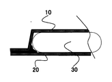
図1に本発明電池A1の封止部分作製前の部分断面図、図2に本発明電池A1の封止部の部分断面図を示す。
図中、10は第1の金属ラミネートシート、20は第2の金属ラミネートシート、30は電極体、40はポリプロピレン製の封止部材、50は封止上型、60は封止下型を示す。
図1に本発明電池A1の封止部分作製前の部分断面図、図2に本発明電池A1の封止部の部分断面図を示す。
図中、10は第1の金属ラミネートシート、20は第2の金属ラミネートシート、30は電極体、40はポリプロピレン製の封止部材、50は封止上型、60は封止下型を示す。
図2に示すように、第1の金属ラミネートシートに形成されたカップ成形部に電極体を収納し、第2の金属ラミネートシートでカップ成形部を閉塞するとともに、第1及び第2の金属ラミネートシートの外縁に設けた封止部(2.8mm幅)を、封止上型50と封止下型60で加圧・加熱を行いながら封止する。図示を省略しているが、封止上型50、封止下型60の各々には、埋設された加熱ヒーターが存在する。
この封止の際、封止部の第1の金属ラミネートシート10と第2の金属ラミネートシート20の間に封止部材40が挟み込まれた状態で加圧・加熱封止される。
このように第1及び第2の金属ラミネートシートの間に封止部材40を配置することにより、加圧・加熱封止後の封止部分では、封止部材が溶融して、封止部と電極体で構成される隙間に流れ出す。
このように第1及び第2の金属ラミネートシートの間に封止部材40を配置することにより、加圧・加熱封止後の封止部分では、封止部材が溶融して、封止部と電極体で構成される隙間に流れ出す。
これにより、封止部と溶融した封止部材とが一体となり新たな封止部を構成し、通常よりも長い封止幅とすることができる。
従って、封止部材を挟み込んだ分、封止されている距離が長くなるので、封止の信頼性は格段と向上することになる。
従って、封止部材を挟み込んだ分、封止されている距離が長くなるので、封止の信頼性は格段と向上することになる。
また、例え、封止部の幅を短くしても、その短くなった分を溶融した封止部材が補うことができるので、封止部の幅が短くても従来と同等以上の封止の信頼性を得ることが可能となる。
なお、本発明では、同一シートを折り曲げて、第1の金属ラミネートシートと第2の金属ラミネートシートとすることにより、封止部は3箇所になったが、第1の金属ラミネートシートと第2の金属ラミネートシートを別部材としても良い。この場合の封止部は4箇所になる。
なお、本発明では、同一シートを折り曲げて、第1の金属ラミネートシートと第2の金属ラミネートシートとすることにより、封止部は3箇所になったが、第1の金属ラミネートシートと第2の金属ラミネートシートを別部材としても良い。この場合の封止部は4箇所になる。
(実施例2)
封止部の幅を、2.0mmとする以外は、実施例1と同様にしてラミネート外装電池を作製した。この電池を本発明電池A2とする。
封止部の幅を、2.0mmとする以外は、実施例1と同様にしてラミネート外装電池を作製した。この電池を本発明電池A2とする。
(実施例3)
封止部の幅を、1.5mmとする以外は、実施例1と同様にしてラミネート外装電池を作製した。この電池を本発明電池A3とする。
封止部の幅を、1.5mmとする以外は、実施例1と同様にしてラミネート外装電池を作製した。この電池を本発明電池A3とする。
(比較例1)
図3及び図4に示すように、金属ラミネートシートの間に部材を挟み込まず封止する以外は、実施例1と同様にしてラミネート外装電池を作製した。この電池を比較電池X1とする。
図3及び図4に示すように、金属ラミネートシートの間に部材を挟み込まず封止する以外は、実施例1と同様にしてラミネート外装電池を作製した。この電池を比較電池X1とする。
6.封止信頼性特性
本発明電池A1~A3、比較電池X1を用いて封止信頼性の実験を行った。
上記各電池3セルを常温(約25℃)下で、3600mAの定電流で24分間充電(満充電に対して40%充電状態)した。このときの電池厚みを保存前電池厚みとした。
次いで、充電状態の各電池を80℃、90%の恒温槽中に放置した。
その後、5日目、10日目、15日目、20日目に各電池を取り出し、各日における保存後の電池厚みを測定し、以下の計算式により電池膨れ率(%)を求めた。
電池膨れ率(%)=((各日の保存後の電池厚み-保存前の電池厚み)/保存前の電池厚み)×100
なお、電池膨れ率(%)は、各電池の3セルの平均値である。
図5に、放置日数と電池膨れ率(%)の関係を示す。
また、10日後、20日後の結果を表1に示す。

上記図5及び表1の結果から明らかなように、本発明電池A1~A3の10日目の電池膨れ率は1.1%~3.2%であり、比較電池X1は4.3%であった。また、本発明電池A1~A3の20日目の電池膨れ率は3.9%~11.6%であり、比較電池X1は15.5%であった。この結果から、本発明電池A1~A3は、比較電池X1に比べ、電池膨れ率が非常に低いことが判る。
以上のことから、本発明電池A1~A3は、例え封止部の幅を短くしても、比較電池X1よりも優れた封止信頼性を有していることが判る。
この理由は、封止部における第1及び第2の金属ラミネートシートの間に、金属ラミネートシートの内側樹脂よりも融点が同じもしくは低い封止部材を挟み込んでいるので、封止部を熱溶着する際に、封止部材も溶け出し、封止部と電極体で構成された隙間に流れ出し封止部と一体的な封止構造を構成したからであると考えられる。
このような封止構造により、水分が電池内部に透過することを防止でき、電池の膨れを抑制できたと考える。
この理由は、封止部における第1及び第2の金属ラミネートシートの間に、金属ラミネートシートの内側樹脂よりも融点が同じもしくは低い封止部材を挟み込んでいるので、封止部を熱溶着する際に、封止部材も溶け出し、封止部と電極体で構成された隙間に流れ出し封止部と一体的な封止構造を構成したからであると考えられる。
このような封止構造により、水分が電池内部に透過することを防止でき、電池の膨れを抑制できたと考える。
7.その他事項
本発明で使用し得る正極活物質としては、LiCoO2、LiNiO2、LiMn2O4、LiMnO2、LiNi1-xMnxO2(0<x<1)、LiNi1-xCoxO2(0<x<1)、LiNixMnyCozO2(0<x、y、z<1、x+y+z=1)などのリチウム複合酸化物又はLiFePO4などのオリビン構造を有するリン酸化合物が好ましい。
本発明で使用し得る正極活物質としては、LiCoO2、LiNiO2、LiMn2O4、LiMnO2、LiNi1-xMnxO2(0<x<1)、LiNi1-xCoxO2(0<x<1)、LiNixMnyCozO2(0<x、y、z<1、x+y+z=1)などのリチウム複合酸化物又はLiFePO4などのオリビン構造を有するリン酸化合物が好ましい。
また、本発明で使用し得る負極活物質としては、黒鉛、難黒鉛化性炭素及び易黒鉛化性炭素などの炭素原料、LiTiO2及びTiO2などのチタン酸化物、ケイ素及びスズなどの半金属元素、またはSn-Co合金等が挙げられる。
また、本発明で使用し得る非水溶媒としては、エチレンカーボネート(EC)、プロピレンカーボネート(PC)、ブチレンカーボネート(BC)などの環状炭酸エステル、フッ素化された環状炭酸エステル、γ-ブチルラクトン(BL)、γ-バレロラクトン(VL)などの環状カルボン酸エステル、ジメチルカーボネート(DMC)、エチルメチルカーボネート(EMC)、ジエチルカーボネート(DEC)、メチルプロピルカーボネート(MPC)、ジブチルカーボネート(DNBC)などの鎖状炭酸エステル、ピバリン酸メチル、ピバリン酸エチル、メチルイソブチレート、メチルプロピオネートなどの鎖状カルボン酸エステル、N、N'-ジメチルホルムアミド、N-メチルオキサゾリジノンなどのアミド化合物、スルホランなどの硫黄化合物、テトラフルオロ硼酸1-エチル-3-メチルイミダゾリウムなどの常温溶融塩などが例示できる。これらは2種以上混合して用いることが望ましい。この中でもEC、PC、鎖状炭酸エステル、3級カルボン酸エステルが特に好ましい。
また、本発明で使用する非水溶媒中に溶解させる電解質塩としては、このようなリチウム塩としては、LiPF6、LiBF4、LiCF3SO3、LiN(CF3SO2)2、LiN(C2F5SO2)2、LiN(CF3SO2)(C4F9SO2)、LiC(CF3SO2)3、LiC(C2F5SO2)3、LiAsF6、LiClO4、Li2B10Cl10、Li2B12Cl12など及びそれらの混合物が例示される。これらの中でも、LiPF6(ヘキサフルオロリン酸リチウム)が特に好ましい。前記非水溶媒に対する電解質塩の溶解量は、0.5~2.0mol/Lとするのが好ましい。
なお、本発明で使用する非水電解液中には、電極の安定化用化合物として、さらに、ビニレンカーボネート(VC)、ビニルエチルカーボネート(VEC)、無水コハク酸(SUCAH)、無水マイレン酸(MAAH)、グリコール酸無水物、エチレンサルファイト(ES)、ジビニルスルホン(VS)、ビニルアセテート(VA)、ビニルピバレート(VP)、カテコールカーボネート、ビフェニル(BP)などを添加してもよい。これらの化合物は、2種以上を適宜に混合して用いることができる。
なお、上述した実施の形態においては、本発明をラミネート外装電池に適用する例について説明したが、非水電解質としてポリマー電解質を用いた場合でも、本発明と同様の効果が得られることは明らかである。
10…第1の金属ラミネートシート
20…第2の金属ラミネートシート
30…電極体
40…ポリプロピレン製の封止部材
50…封止上型
60…封止下型
20…第2の金属ラミネートシート
30…電極体
40…ポリプロピレン製の封止部材
50…封止上型
60…封止下型
Claims (2)
- 金属層と樹脂層とを積層してなる第1及び第2の金属ラミネートシートとの間に形成される内部空間に電極体を収納し、前記第1及び第2の金属ラミネートシートの外縁の前記樹脂層同士を熱溶着により封止して封止部を形成したラミネート外装電池において、
前記封止部の前記第1と第2の金属ラミネートシートの間から、前記第1及び第2の金属ラミネートシートで形成される内部空間にかけて、前記樹脂層と比較して融点が同じもしくは低い封止部材が配置され、
当該封止部材が、前記第1及び第2の金属ラミネートシートの前記樹脂層と溶着していることを特徴とするラミネート外装電池。 - 金属層と樹脂層とを積層してなる第1及び第2の金属ラミネートシートとの間に形成される内部空間に電極体を収納し、前記第1及び第2の金属ラミネートシートの外縁の間に、前記樹脂層と比較して融点が同じもしくは低い封止部材を配置して積層し、これら積層した部分を熱溶着して封止することにより、溶融した前記封止部材を前記第1及び第2の金属ラミネートシートで形成される内部空間に流れ出させることを特徴とするラミネート外装電池の製造方法。
Applications Claiming Priority (2)
| Application Number | Priority Date | Filing Date | Title |
|---|---|---|---|
| JP2010265846 | 2010-11-30 | ||
| JP2010-265846 | 2010-11-30 |
Publications (1)
| Publication Number | Publication Date |
|---|---|
| WO2012073748A1 true WO2012073748A1 (ja) | 2012-06-07 |
Family
ID=46171691
Family Applications (1)
| Application Number | Title | Priority Date | Filing Date |
|---|---|---|---|
| PCT/JP2011/076852 Ceased WO2012073748A1 (ja) | 2010-11-30 | 2011-11-22 | ラミネート外装電池及びその製造方法 |
Country Status (1)
| Country | Link |
|---|---|
| WO (1) | WO2012073748A1 (ja) |
Citations (2)
| Publication number | Priority date | Publication date | Assignee | Title |
|---|---|---|---|---|
| JP2001357826A (ja) * | 2000-06-15 | 2001-12-26 | Yuasa Corp | 密閉形電池および密閉形電池の製造方法 |
| JP2004095308A (ja) * | 2002-08-30 | 2004-03-25 | Toshiba Corp | 非水電解質二次電池 |
-
2011
- 2011-11-22 WO PCT/JP2011/076852 patent/WO2012073748A1/ja not_active Ceased
Patent Citations (2)
| Publication number | Priority date | Publication date | Assignee | Title |
|---|---|---|---|---|
| JP2001357826A (ja) * | 2000-06-15 | 2001-12-26 | Yuasa Corp | 密閉形電池および密閉形電池の製造方法 |
| JP2004095308A (ja) * | 2002-08-30 | 2004-03-25 | Toshiba Corp | 非水電解質二次電池 |
Similar Documents
| Publication | Publication Date | Title |
|---|---|---|
| EP2639876B1 (en) | Nonaqueous electrolyte secondary battery | |
| JP6521883B2 (ja) | 非水電解液電池、およびその製造方法 | |
| JP6138436B2 (ja) | 非水電解質二次電池及びその製造方法 | |
| JP6384477B2 (ja) | リチウムイオン二次電池およびその製造方法 | |
| JP6165425B2 (ja) | 非水電解質二次電池及びその製造方法 | |
| JP6097030B2 (ja) | 非水電解質二次電池及びその製造方法 | |
| WO2016068286A1 (ja) | 非水電解質電池及び電池パック | |
| JP2014035939A (ja) | 非水電解質二次電池 | |
| JP6602050B2 (ja) | 電池 | |
| JP2014179220A (ja) | ラミネート外装電池 | |
| WO2016013179A1 (ja) | 非水電解質二次電池 | |
| JP2014035929A (ja) | 非水電解質二次電池 | |
| JP2012156069A (ja) | ラミネート外装電池 | |
| CN114503300A (zh) | 一种改善电极组件安全性的极片及包含其的电化学装置、电子装置 | |
| WO2019193690A1 (ja) | 非水電解質電池及び電池パック | |
| JP5793411B2 (ja) | リチウム二次電池 | |
| JP5897271B2 (ja) | 非水電解質二次電池 | |
| JP2013118069A (ja) | リチウム二次電池 | |
| JP6104536B2 (ja) | 非水電解質二次電池及びその製造方法 | |
| JP5964102B2 (ja) | 扁平電極体を備えた電池の製造方法 | |
| JP5869354B2 (ja) | 角形リチウムイオン二次電池用外装缶および角形リチウムイオン二次電池 | |
| CN112542569B (zh) | 一种电极组件及包含其的电化学装置、电子装置 | |
| WO2017110842A1 (ja) | 非水二次電池およびその製造方法 | |
| KR101592196B1 (ko) | 물성이 상이한 고분자 복합막을 구비하는 라미네이트 시트 | |
| KR101613079B1 (ko) | 분리된 두 개의 수납부를 포함하는 전지 케이스 및 리튬 이차전지 |
Legal Events
| Date | Code | Title | Description |
|---|---|---|---|
| 121 | Ep: the epo has been informed by wipo that ep was designated in this application |
Ref document number: 11846025 Country of ref document: EP Kind code of ref document: A1 |
|
| NENP | Non-entry into the national phase |
Ref country code: DE |
|
| 122 | Ep: pct application non-entry in european phase |
Ref document number: 11846025 Country of ref document: EP Kind code of ref document: A1 |
|
| NENP | Non-entry into the national phase |
Ref country code: JP |