WO2012073347A1 - 負圧供給システム - Google Patents
負圧供給システム Download PDFInfo
- Publication number
- WO2012073347A1 WO2012073347A1 PCT/JP2010/071436 JP2010071436W WO2012073347A1 WO 2012073347 A1 WO2012073347 A1 WO 2012073347A1 JP 2010071436 W JP2010071436 W JP 2010071436W WO 2012073347 A1 WO2012073347 A1 WO 2012073347A1
- Authority
- WO
- WIPO (PCT)
- Prior art keywords
- negative pressure
- cylinders
- control valve
- fuel
- engine
- Prior art date
- Legal status (The legal status is an assumption and is not a legal conclusion. Google has not performed a legal analysis and makes no representation as to the accuracy of the status listed.)
- Ceased
Links
Images



Classifications
-
- B—PERFORMING OPERATIONS; TRANSPORTING
- B60—VEHICLES IN GENERAL
- B60T—VEHICLE BRAKE CONTROL SYSTEMS OR PARTS THEREOF; BRAKE CONTROL SYSTEMS OR PARTS THEREOF, IN GENERAL; ARRANGEMENT OF BRAKING ELEMENTS ON VEHICLES IN GENERAL; PORTABLE DEVICES FOR PREVENTING UNWANTED MOVEMENT OF VEHICLES; VEHICLE MODIFICATIONS TO FACILITATE COOLING OF BRAKES
- B60T17/00—Component parts, details, or accessories of power brake systems not covered by groups B60T8/00, B60T13/00 or B60T15/00, or presenting other characteristic features
- B60T17/02—Arrangements of pumps or compressors, or control devices therefor
-
- F—MECHANICAL ENGINEERING; LIGHTING; HEATING; WEAPONS; BLASTING
- F02—COMBUSTION ENGINES; HOT-GAS OR COMBUSTION-PRODUCT ENGINE PLANTS
- F02D—CONTROLLING COMBUSTION ENGINES
- F02D41/00—Electrical control of supply of combustible mixture or its constituents
- F02D41/0002—Controlling intake air
- F02D41/0005—Controlling intake air during deceleration
-
- F—MECHANICAL ENGINEERING; LIGHTING; HEATING; WEAPONS; BLASTING
- F02—COMBUSTION ENGINES; HOT-GAS OR COMBUSTION-PRODUCT ENGINE PLANTS
- F02D—CONTROLLING COMBUSTION ENGINES
- F02D41/00—Electrical control of supply of combustible mixture or its constituents
- F02D41/02—Circuit arrangements for generating control signals
- F02D41/04—Introducing corrections for particular operating conditions
- F02D41/12—Introducing corrections for particular operating conditions for deceleration
- F02D41/123—Introducing corrections for particular operating conditions for deceleration the fuel injection being cut-off
-
- F—MECHANICAL ENGINEERING; LIGHTING; HEATING; WEAPONS; BLASTING
- F02—COMBUSTION ENGINES; HOT-GAS OR COMBUSTION-PRODUCT ENGINE PLANTS
- F02D—CONTROLLING COMBUSTION ENGINES
- F02D2250/00—Engine control related to specific problems or objectives
- F02D2250/41—Control to generate negative pressure in the intake manifold, e.g. for fuel vapor purging or brake booster
-
- Y—GENERAL TAGGING OF NEW TECHNOLOGICAL DEVELOPMENTS; GENERAL TAGGING OF CROSS-SECTIONAL TECHNOLOGIES SPANNING OVER SEVERAL SECTIONS OF THE IPC; TECHNICAL SUBJECTS COVERED BY FORMER USPC CROSS-REFERENCE ART COLLECTIONS [XRACs] AND DIGESTS
- Y02—TECHNOLOGIES OR APPLICATIONS FOR MITIGATION OR ADAPTATION AGAINST CLIMATE CHANGE
- Y02T—CLIMATE CHANGE MITIGATION TECHNOLOGIES RELATED TO TRANSPORTATION
- Y02T10/00—Road transport of goods or passengers
- Y02T10/10—Internal combustion engine [ICE] based vehicles
- Y02T10/40—Engine management systems
Definitions
- the present invention relates to a negative pressure supply system, and more particularly to a negative pressure supply system that supplies a negative pressure to a vacuum booster used in a vehicle brake device.
- the conventional negative pressure supply system uses the intake air in the combustion chamber of the engine to generate a negative pressure (vacuum) and supplies this negative pressure to the vacuum booster (vacuum booster).
- Boost the brake.
- it is proposed in Japanese Patent Application Laid-Open Nos. 2004-3473 and 2008-267255.
- Japanese Patent Laid-Open No. 2000-234522 describes that a low-leakage air valve is used as an air valve provided in the intake manifold.
- Such a negative pressure supply system generates a negative pressure downstream of the butterfly valve by closing the intake manifold.
- a typical engine has a butterfly valve (or choke) in the intake manifold. The purpose of this valve is to limit the air flow to the combustion chamber. Such a valve does not seal the conduit even when in the fully closed position. This is because such a valve is only used in the combustion chamber to restrict the airflow to some extent.
- the combustion chamber sucks air from the intake manifold as the engine rotates.
- Limiting the flow of air to the combustion chamber by the butterfly valve is done by moving the valve to a partially closed position or a fully closed position. While the valve is in the closed position, a negative pressure region is created between the valve and the combustion chamber as the combustion chamber draws air.
- a normal brake booster system supplies negative pressure to the brake booster by connecting this negative pressure region to the brake booster via a pipe line.
- a conventional negative pressure supply system 100 is shown in the conceptual diagram of FIG.
- the negative pressure supply system 100 includes an intake manifold 5 connected to an air intake 3 of the vehicle, and the intake manifold 5 is connected to intake ports of the combustion chambers of the cylinders 7a to 7d through branch lines.
- Each intake port is provided with an intake valve (not shown).
- an exhaust port is provided in the combustion chambers of the cylinders 7a to 7d, the exhaust port is connected to the exhaust manifold 9, and an exhaust valve (not shown) is provided in the exhaust port.
- the intake manifold 5 is provided with an airflow control valve 11.
- an object of the present invention is to provide a negative pressure generating system capable of supplying a sufficient negative pressure to a negative pressure operating device such as a brake booster without using the general alternative means described above.
- a negative pressure generation system is a negative pressure generation system using an engine, wherein the engine includes a plurality of cylinders and a plurality of pistons provided in each of the plurality of cylinders, An intake manifold for supplying air to the plurality of cylinders; fuel supply means for supplying fuel to the plurality of cylinders; and a plurality of spark plugs for igniting fuel in each of the plurality of cylinders;
- the pressure generation system includes a negative pressure control valve provided between the intake manifold and the plurality of cylinders, a negative pressure supply line connected to the intake manifold downstream from the negative pressure control valve, and the negative pressure A negative pressure operating device connected to a supply line; and a control means for controlling the operation of the negative pressure control valve and the engine, wherein the control means includes the engine During operation, at least one of the at least one cylinder is closed by closing the intake manifold by the negative pressure control valve and stopping supply of fuel to at least one of the plurality of cylinders
- Negative pressure is generated by the movement of two pistons.
- the control means supplies the fuel to the other cylinders of the plurality of cylinders by the fuel supply means and burns the fuel in the other cylinders when the fuel supply is stopped.
- the at least one piston is operated in conjunction with the movement of the piston.
- An airflow control valve is provided in the intake manifold upstream of the intake control valve.
- the at least one cylinder is a single cylinder.
- the control means closes the intake control valve to stop the supply of air to the single cylinder, and stops the supply of fuel to the single cylinder by the fuel supply means.
- the intake manifold includes a plurality of branch pipes that provide air to each of the plurality of cylinders, and the negative pressure control valve is provided in the branch pipe to the single cylinder, and the negative pressure supply A conduit is connected between the negative pressure control valve and the single cylinder.
- the negative pressure operating device is a brake booster.
- a sealing material is provided for sealing between the intake control valve and the intake manifold.
- the negative pressure generation system of the present invention since the negative pressure can be supplied by at least one cylinder, the negative pressure required for the negative pressure operating device can be provided without using an expensive and heavy vacuum pump.
- the negative pressure generation system of the present invention can provide the negative pressure necessary for the negative pressure operation device without using an expensive exhaust gas decomposition catalyst that functions in a low temperature condition at the start of the engine.
- each embodiment of the present invention is applied to an engine having a plurality of cylinders, and the combustion chamber of each cylinder is premised on a four-valve type with two intake valves and two exhaust valves.
- the present invention is not limited to this, and any of a two-valve type, a three-valve type, and a five-valve type is applicable.
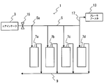
- FIG. 1 is a conceptual diagram of a negative pressure supply system 1 according to a first embodiment of the present invention.
- the intake manifold 5 is provided with a negative pressure control valve 15 upstream of the branch portion 5 a of the intake manifold 5 in place of the airflow control valve 11 of FIG. 6.
- a butterfly valve can be used as the negative pressure control valve 15.
- an elastic seal member is attached to the negative pressure control valve 15 so that the intake manifold 5 can be completely sealed when the negative pressure control valve 15 is closed.
- a negative pressure supply line 17 is connected between the negative pressure control valve 15 and the intake ports of the cylinders 7 a to 7 d, and the negative pressure supply line 17 supplies a negative pressure to the brake booster 13.
- FIG. 2 is a block diagram of the negative pressure supply system 1 of FIG.
- the electronic control unit (ECU) 19 of the vehicle receives a detection signal from the negative pressure control valve angle sensor 15 a and the negative pressure sensor 23 that measures the negative pressure in the negative pressure supply pipe 17.
- the ECU 19 controls opening and closing of the negative pressure control valve 15 and the fuel injection valve 21 that supplies fuel to each of the cylinders 7a to 7d. Further, the ECU 19 controls the opening and closing of the intake valve 23 and the exhaust valve 25 provided in each of the cylinders 7a to 7d, and controls the ignition of the spark plug 27 provided in each of the cylinders 7a to 7d.
- the first embodiment is preferably performed when the engine speed is high to some extent and the load is relatively small (for example, when going down a slope).
- the negative pressure control valve 15 is closed, simultaneously the fuel injection valves to the cylinders 7a to 7d are also closed, and ignition of the ignition plugs of the cylinders 7a to 7d is also stopped.
- the cylinders 7a to 7d operate as a vacuum pump, and negative pressure can be provided to the brake booster 13.
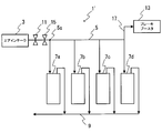
- the negative pressure supply system 1 ′ of the second embodiment is provided with a negative pressure control valve 15 downstream of the air flow control valve 11 of the intake manifold 5 and upstream of the branch portion 5 a of the intake manifold 5 as shown in FIG. 3.
- the airflow control valve 11 and the negative pressure control valve 15 can be operated independently.
- FIG. 4 is a block diagram of the negative pressure supply system 1 'of FIG.
- the electronic control unit (ECU) 19 of the vehicle also receives a detection signal from the airflow control valve angle sensor 17 a and controls the opening and closing of the airflow control valve 17.
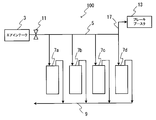
- the negative pressure supply system 1 ′′ of the third embodiment is provided with a negative pressure control valve 15 in a branch line 5b between a branch portion 5a of the intake manifold 5 and an intake port of the cylinder 7a.
- negative pressure can be generated by sealing the branch pipe 5b that sucks into the cylinder 7a with the negative pressure control valve 15.
- the pistons of the cylinders 7a to 7d are All of them are connected by a crankshaft.
- the combustion chambers of the cylinders 7b to 7d perform combustion, so that the pistons of the cylinders 7b to 7d operate by themselves. Therefore, negative pressure is generated by the operation of the driven piston of the cylinder 7a while maintaining the engine output by the pistons of the cylinders 7b to 7d.
- Door can be.
- one cylinder 7a is operated as a vacuum pump.
- the present invention is not limited to this, and a plurality of cylinders can be used instead of the vacuum pump.
- the negative pressure control valves 15 are provided in a plurality of cylinders, and these are simultaneously controlled to be opened and closed, whereby the necessary negative pressure can be generated with a smaller number of times.
- the negative pressure supply system of the present invention forms a sealable portion between the intake manifold and the combustion chamber of the cylinder, so that a negative pressure is generated as the combustion chamber sucks in air.
- a sufficient negative pressure can be supplied to the vacuum booster via the pressure supply line 17.
- the fuel supply to the combustion chamber of each cylinder in the negative pressure supply mode is interrupted in synchronism with the execution of sealing. This is to prevent the fuel from becoming rich (in an extreme case, all fuel is free of air).
- the ignition plug 27 of each cylinder in the negative pressure supply mode is not ignited.
- each embodiment of the present invention the pistons of the cylinders 7a to 7d are always operating when the engine is driven.
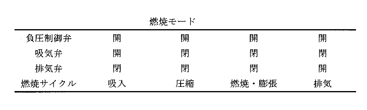
- the combustion chamber of each cylinder has a negative pressure supply mode in the state of Table 1 and a combustion mode in the state of Table 2.
- the negative pressure is generated by the movement of the piston of the cylinder in the negative pressure supply mode. Therefore, the cylinder deactivation that stops the movement of the piston of the specific cylinder has a fundamental technical idea. Is different.
- a sufficient negative pressure can be provided to the booster system within a very small engine speed.
- a 3000 cc brake booster is provided in the case of an engine having a displacement of 1000 cc with 4 cylinders (the displacement of 1 cylinder is 250 cc).
- one cylinder 7a in the negative pressure generation mode can sufficiently exhaust the brake booster within 12 rotations.
- the present invention does not significantly reduce engine torque even under any conditions during operation or idling.
- the following events (1) and (2) are expected.
- (1) For example, in the case of the third embodiment, when the engine speed is 400 rpm and only the three cylinders 7b to 7d are set to the combustion mode, the engine speed is 300 rpm and the four cylinders 7a to 7d are used. All produce the same amount of combustion gas as when in combustion mode. The time required for 12 revolutions of the piston at 800 rpm is 0.9 seconds.
- the negative pressure generated by the negative pressure generation system is used in the brake booster system, but the present invention can be used for other systems that use negative pressure as a power source.
- the negative pressure generated by the negative pressure generation system can be used for a changeover switch between two-wheel drive and four-wheel drive.
- the negative pressure generation system is configured to limit the intake air flow to a specific combustion chamber even when the engine is at a low rotation speed (the threshold value of the rotation speed is limited to a predetermined value). Can be generated.
- the negative pressure generation system of this embodiment has the following effects (1) to (3).
Landscapes
- Engineering & Computer Science (AREA)
- Mechanical Engineering (AREA)
- Chemical & Material Sciences (AREA)
- Combustion & Propulsion (AREA)
- General Engineering & Computer Science (AREA)
- Transportation (AREA)
- Output Control And Ontrol Of Special Type Engine (AREA)
Abstract
本発明の負圧生成システム1はエンジンを用いる。エンジンは、ピストンを有するシリンダ7a~7dと、シリンダ7a~7dに空気を提供する吸気マニホルド5と、シリンダに燃料を供給する燃料供給手段とを有する。負圧生成システム1は、吸気マニホルド5から前記複数のシリンダ7a~7dへの吸気を制御して負圧を制御する負圧制御弁15と、吸気マニホルド5に接続される負圧供給管路17と、負圧供給管路17に接続されるブレーキブースタ13と、負圧制御弁15及びエンジンの動作を制御するECUとを備える。ECUは、エンジンの動作中に負圧制御弁15により吸気マニホルド5を閉鎖し、かつ燃料噴射弁によるシリンダへの燃料の供給を停止することにより、シリンダを真空ポンプとして動作させて負圧を生成する。
Description
本発明は、負圧供給システムに関し、より詳細には車両用ブレーキ装置に用いるバキュームブースタに負圧を供給する負圧供給システムに関する。
従来の負圧供給システムは、エンジンの燃焼室の吸気を利用して、負圧(真空)を生成して、この負圧をバキュームブースタ(真空倍力装置)に提供して、バキュームブースタが車両用ブレーキをブーストする。例えば、特開2004-3473号公報、特開2008-267255号公報等に提案されている。
また、特開2000-234522号公報には、吸気マニホルドに設けられるエアバルブとして、低リークエアバルブを用いることが記載されている。
このような負圧供給システムは、バタフライ弁が吸気マニホルドを閉じることにより、その下流で負圧を生成する。通常のエンジンでは、バタフライ弁(又はチョーク)を、吸気マニホルド内に有する。この弁の目的は、燃焼室への空気流を制限することにある。このような弁は、完全に閉じた位置にあるときでも、管路を密閉しない。なぜなら、このような弁は燃焼室の中で、気流をある程度の制限することにのみ用いられる。
このようなエンジンの負圧供給システムにおいて、エンジンの回転により、燃焼室は吸気マニホルドから空気を吸い込む。バタフライ弁による燃焼室への空気の流れの制限は、弁を部分的に閉じた位置、又は十分に閉じた位置に移動することにより行われる。弁が前記閉じた位置にある間に、燃焼室が空気を吸い込むことにより、負圧領域が弁と燃焼室との間に生成される。通常のブレーキブースタシステムは、負圧を利用するために、管路を介してこの負圧領域を前記ブレーキブースタに接続することにより、前記ブレーキブースタに負圧を供給する。
従来の負圧供給システム100を図6の概念図に示す。負圧供給システム100は、車両のエアインテーク3に接続された吸気マニホルド5を備え、吸気マニホルド5は、分岐管路を介してシリンダ7a~7dの燃焼室の吸気ポートに接続される。各吸気ポートには、図示しない吸気弁が設けられる。さらに、シリンダ7a~7dの燃焼室には排気ポートが設けられ、排気ポートは排気マニホルド9に接続され、排気ポートには図示しない排気弁が設けられる。吸気マニホルド5には気流制御弁11が設けられており、エンジンの動作中に気流制御弁11を閉位置にすると、ピストンの動作に伴って、気流制御弁11の下流とシリンダ7a~7dとの間に負圧が生成される。この負圧は、負圧供給管路17によりブレーキブースタ13に供給される。
従来の気流制御弁11は完全に密閉されないので、必要な負圧(真空)を達成又は維持するためには、空気が気流制御弁11を介して吸気マニホルドを流れるよりも、より早く空気を吸引する必要がある(即ち、エンジンを高回転数にする必要がある)。
しかしながら、エンジンの高回転数と、気流制御弁を流れる低速の空気流との間でバランスを達成又は維持することが実行可能でないとき、従来の負圧供給システムでは、ブレーキブースタに十分な負圧を供給できない。例えば、以下の(1)や(2)の場合である。
(1)エンジンは始動時に高回転数とすることはできない。なぜなら、全体のシステムが冷えており、高回転数により増大した排気ガス量を分解することができないからである。
特に、停止していたエンジンを始動して車両をスタートする時には、エンジンが低回転数であるため、十分な負圧をブレーキブースタに提供できない場合が生じる。そこで、スタート時に、十分な負圧をブレーキブースタに提供するために、エンジンを高回転数にすると、排ガス分解触媒が作動温度に上昇する前に多量の排ガスが発生し、このような排ガスを排ガス分解触媒が分解できず、排ガス規制をクリアできないおそれが生じる。
(2)図6に示すような負圧供給システム100では、気流制御弁11により空気の流れを完全に制限することはできない。なぜなら、負圧を生成するために、エンジンで燃焼工程を行う必要があり、空気を必要とするからである。
これらの課題を処理するための代替的な手段として、ブレーキブースタ用の真空ポンプを別途設けたり、低温条件で機能する排気ガス処理触媒を採用することが考えられる。しかしながら、これらの手段は、非常に高価でありかなり重く大きな空間を占めるという問題が生じる。
(1)エンジンは始動時に高回転数とすることはできない。なぜなら、全体のシステムが冷えており、高回転数により増大した排気ガス量を分解することができないからである。
特に、停止していたエンジンを始動して車両をスタートする時には、エンジンが低回転数であるため、十分な負圧をブレーキブースタに提供できない場合が生じる。そこで、スタート時に、十分な負圧をブレーキブースタに提供するために、エンジンを高回転数にすると、排ガス分解触媒が作動温度に上昇する前に多量の排ガスが発生し、このような排ガスを排ガス分解触媒が分解できず、排ガス規制をクリアできないおそれが生じる。
(2)図6に示すような負圧供給システム100では、気流制御弁11により空気の流れを完全に制限することはできない。なぜなら、負圧を生成するために、エンジンで燃焼工程を行う必要があり、空気を必要とするからである。
これらの課題を処理するための代替的な手段として、ブレーキブースタ用の真空ポンプを別途設けたり、低温条件で機能する排気ガス処理触媒を採用することが考えられる。しかしながら、これらの手段は、非常に高価でありかなり重く大きな空間を占めるという問題が生じる。
そこで、本発明は、上述した一般的な代替的な手段を用いずに、十分な負圧をブレーキブースタ等の負圧動作装置に供給することができる負圧発生システムの提供を目的とする。
上記目的を達成するために、本発明の負圧生成システムは、エンジンを用いた負圧生成システムにおいて、前記エンジンは、複数のシリンダと、前記複数のシリンダのそれぞれに設けられる複数のピストンと、前記複数のシリンダに空気を供給する吸気マニホルドと、前記複数のシリンダに燃料を供給する燃料供給手段と、前記複数のシリンダのそれぞれの中で燃料に着火する複数の点火プラグとを備え、前記負圧生成システムは、前記吸気マニホルドと前記複数のシリンダとの間に設けられる負圧制御弁と、前記負圧制御弁より下流で前記吸気マニホルドに接続される負圧供給管路と、前記負圧供給管路に接続される負圧動作装置と、前記負圧制御弁及び前記エンジンの動作を制御する制御手段とを備え、前記制御手段は、前記エンジンの動作中に前記負圧制御弁により前記吸気マニホルドを閉し、かつ前記燃料供給手段による前記複数のシリンダの少なくとも一つのシリンダへの燃料の供給を停止することにより、前記少なくとも一つのシリンダの少なくとも一つのピストンの運動により負圧を生成する。前記制御手段は、前記燃料供給の停止時に、前記複数のシリンダの他のシリンダに、前記燃料供給手段により燃料を供給して前記燃料を前記他のシリンダ内で燃焼させることにより、前記他のシリンダのピストンの運動に連動して前記少なくとも一つのピストンを動作させる。前記吸気制御弁より上流の前記吸気マニホルドに気流制御弁を備える。前記少なくとも一つのシリンダは、単一のシリンダである。前記制御手段は、前記吸気制御弁を閉じて前記単一のシリンダへの空気の供給を停止し、また前記燃料供給手段による前記単一のシリンダへの燃料の供給を停止する。
前記吸気マニホルドは、前記複数のシリンダのそれぞれに空気を提供する、複数の分岐管路を備え、前記負圧制御弁は、前記単一のシリンダへの分岐管路に設けられ、前記負圧供給管路は、前記負圧制御弁と前記単一のシリンダとの間に接続される。
前記負圧動作装置は、ブレーキブースタである。前記吸気制御弁と前記吸気マニホルドとの間を密閉するためのシール材を備える。前記少なくとも一つのシリンダへの燃料の供給が停止された時に、前記制御手段は、前記少なくとも一つの点火プラグの着火を停止する。
本発明の負圧生成システムによれば、少なくとも1つのシリンダにより負圧を供給できるため、高価で重い真空ポンプを使用することなしに、負圧動作装置に必要な負圧を提供できる。また、本発明の負圧生成システムは、エンジンの始動時の低温条件で機能するような高価な排気ガス分解触媒を使用することなしに、負圧動作装置に必要な負圧を提供できる。
本発明の実施形態に係る各負圧供給システムを、図面を参照して説明する。各実施形態で従来の負圧供給システムと同一の部材には、同一符号を付し説明を省略する。また、各実施形態で同一の部材にも同一符号を付し説明を省略する。
本発明の各実施形態の負圧供給システムは、複数のシリンダを有するエンジンに適用されるものであり、各シリンダの燃焼室は吸気弁が2つ排気弁が2つの4弁型を前提とするが、これに限定されず、例えば、2弁型、3弁型、5弁型の何れであっても適用可能である。
本発明の第1の実施形態に係る負圧供給システム1を図1の概念図に示す。図1において、吸気マニホルド5には、図6の気流制御弁11に換えて、吸気マニホルド5の分岐部5aの上流に負圧制御弁15が設けられる。負圧制御弁15としては、バタフライ弁を用いることができる。好ましくは、負圧制御弁15には、弾性シール部材が取り付けられており、負圧制御弁15の閉鎖時に吸気マニホルド5を完全に密閉可能となっている。負圧制御弁15とシリンダ7a~7dの吸気ポートとの間には、負圧供給管路17が接続され、負圧供給管路17は、ブレーキブースタ13に負圧を供給する。
図2は図1の負圧供給システム1のブロック図である。車両の電子制御ユニット(ECU)19は、負圧制御弁角度センサ15a、負圧供給管路17内の負圧を測定する負圧センサ23からの検知信号を受信する。また、ECU19は、負圧制御弁15と、シリンダ7a~7dのそれぞれに燃料を供給する燃料噴射弁21との開閉を制御する。さらに、ECU19は、各シリンダ7a~7dに設けられる吸気弁23及び排気弁25の開閉を制御し、かつ、シリンダ7a~7dのそれぞれに設けられる点火プラグ27の着火を制御する。
第1の実施形態は、好ましくは、エンジンの回転数がある程度高く、負荷が比較的小さい場合(例えば、坂道を下るような場合)に実施される。この場合に、エンジンの駆動中に、負圧制御弁15を閉じて、同時にシリンダ7a~7dへの燃料噴射弁も閉じ、かつシリンダ7a~7dの点火プラグの着火も停止する。これによって、シリンダ7a~7dが真空ポンプとして動作して、負圧をブレーキブースタ13に提供することができる。
第2の実施形態の負圧供給システム1’は、図3に示されるように吸気マニホルド5の気流制御弁11の下流かつ吸気マニホルド5の分岐部5aの上流に負圧制御弁15を設ける。第2の実施形態では、気流制御弁11と、負圧制御弁15とを独立して動作することができる。
図4は図3の負圧供給システム1’のブロック図である。車両の電子制御ユニット(ECU)19は、気流制御弁角度センサ17aからの検知信号も受信し、気流制御弁17の開閉も制御する。
第3の実施形態の負圧供給システム1”は、図5に示されるように吸気マニホルド5の分岐部5aとシリンダ7aの吸気ポートとの間の分岐管路5bに負圧制御弁15を設ける。第3の実施形態では、エンジンの駆動時に、シリンダ7aへ吸気する分岐管路5bを負圧制御弁15で密閉することにより、負圧を発生させることができる。シリンダ7a~7dのピストンは全てクランクシャフトで接続されている。シリンダ7b~7dの燃焼室では燃焼を行うため、シリンダ7b~7dのピストンは自ら動作する。この動作に伴って、燃焼を行わないシリンダ7aの従動ピストンも同期して動作する。したがって、シリンダ7b~7dのピストンによりエンジンの出力を維持しつつ、シリンダ7aの従動ピストンの動作により負圧を発生することができる。
第3の実施形態では、1つのシリンダ7aを真空ポンプとして動作させたがこれに限定されず、複数のシリンダを真空ポンプの代わりに用いることもできる。例えば、複数のシリンダに負圧制御弁15を設け、これらを同時に開閉制御することにより、より少ない回数で必要な負圧を生成できる。
以上説明したように、本発明の負圧供給システムは、吸気マニホルドとシリンダの燃焼室との間に密閉可能な部分を形成することにより、燃焼室が空気を吸い込むにつれて負圧が生成され、負圧供給管路17を介してバキュームブースタに十分な負圧を供給することができる。
好ましくは、負圧供給モードにある各シリンダの燃焼室への燃料供給は、密閉の実行に同期して中断される。これは、燃料がリッチ(極端な場合、全て燃料で空気がない状態)にならないようにするためである。また、好ましくは、負圧供給モードにある各シリンダの点火プラグ27は着火されない。
本発明の各実施形態において、エンジンの駆動時に、シリンダ7a~7dの各ピストンは常に動作している。各シリンダの燃焼室は、表1の状態にある負圧供給モードと、表2の状態にある燃焼モードを有する。

なお、各実施形態においては、負圧供給モードにあるシリンダのピストンの運動により負圧を生成するので、特定のシリンダのピストンの運動を停止するシリンダ・ディアクティベーションとは技術思想が根本的に相違する。
エンジンの回転毎の負圧生成能力は、ブレーキブースタに必要な負圧容量に対して比較的高いので、非常に少ないエンジン回転数内でブースタシステムに十分な負圧を提供できる。例えば、4シリンダで1000ccの排気量のエンジンの場合(1シリンダの排気量は250cc)には、3000ccのブレーキブースタを備える。この場合に、第3の実施形態において、負圧生成モードにある1つのシリンダ7aは、12回転以内でブレーキブースタを十分に排気することができる。本発明は、運転中又はアイドリング中の任意の条件のもとでも、エンジンのトルクを著しく減損することはない。
本発明の負圧生成システムを備えるエンジンがアイドリング状態において、以下の事象(1)、(2)が予想される。
(1)例えば、第3の実施形態の場合に、エンジンの回転数が400rpmで、3つのシリンダ7b~7dのみを燃焼モードとするときに、エンジンの回転数が300rpmで4つのシリンダ7a~7dの全てが燃焼モードのときと、同じ量の燃焼ガスを生成する。800rpmでピストンが12回転するために必要な時間は、0.9秒であり、この場合に、3つのシリンダ7b~7dの燃焼室のみを燃焼モードとすると、これらのシリンダ7b~7dのピストンのそれぞれを、1/3回まで、より早く燃焼させると、エンジン/排気システムの加熱潜在能力は比例して増加し、したがって起動時にエンジン加熱時間の著しい増加を引き起こすことはない。
(2)エンジン負荷が大きい運転条件(例えば、運転者がブレーキを開放しアクセルを最大に踏む)では、次の通りである。エンジン回転数が2000rpmでピストンが12回転に必要な時間は0.36秒であり、ここで、3つのシリンダ7b~7dのみを燃焼モードとするが、燃焼モードにある3つのピストンのそれぞれは、1/3回まで、より多くの空気を利用できる。残る3つのシリンダの加熱潜在能力は、比例して増加し、したがってこの時間間隔でエンジン加熱時間の著しい増加を引き起こすことはない。
(1)例えば、第3の実施形態の場合に、エンジンの回転数が400rpmで、3つのシリンダ7b~7dのみを燃焼モードとするときに、エンジンの回転数が300rpmで4つのシリンダ7a~7dの全てが燃焼モードのときと、同じ量の燃焼ガスを生成する。800rpmでピストンが12回転するために必要な時間は、0.9秒であり、この場合に、3つのシリンダ7b~7dの燃焼室のみを燃焼モードとすると、これらのシリンダ7b~7dのピストンのそれぞれを、1/3回まで、より早く燃焼させると、エンジン/排気システムの加熱潜在能力は比例して増加し、したがって起動時にエンジン加熱時間の著しい増加を引き起こすことはない。
(2)エンジン負荷が大きい運転条件(例えば、運転者がブレーキを開放しアクセルを最大に踏む)では、次の通りである。エンジン回転数が2000rpmでピストンが12回転に必要な時間は0.36秒であり、ここで、3つのシリンダ7b~7dのみを燃焼モードとするが、燃焼モードにある3つのピストンのそれぞれは、1/3回まで、より多くの空気を利用できる。残る3つのシリンダの加熱潜在能力は、比例して増加し、したがってこの時間間隔でエンジン加熱時間の著しい増加を引き起こすことはない。
上記各実施形態では、負圧生成システムが生成する負圧をブレーキブースタシステムに利用した場合を例示したが、動力源として負圧を使用する他のシステムに用いることができる。例えば、負圧生成システムが生成する負圧を、二輪駆動と四輪駆動との切り換えスイッチ等に用いることもできる。
第3の実施形態の負圧生成システムは、エンジンが低回転速度(回転数の閾値は所定値に制限される)であっても、特定の燃焼室への吸気気流を制限することに負圧を生成することができる。
本実施形態の負圧生成システムは、以下の効果(1)~(3)を奏する。
(1)ブレーキブースタシステムのために、高価で重い真空ポンプを使用することなしに、必要な負圧条件を提供できる。
(2)ブレーキブースタシステムの使用において、エンジンの始動時の低温条件で機能するような高価な排気ガス分解触媒を使用することなしに、必要な負圧条件を提供できる。
(3)ブレーキブースタシステムの動作時に、車両の他の機能、例えば空調システム等を停止することなしに、必要な負圧条件を提供できる。
(1)ブレーキブースタシステムのために、高価で重い真空ポンプを使用することなしに、必要な負圧条件を提供できる。
(2)ブレーキブースタシステムの使用において、エンジンの始動時の低温条件で機能するような高価な排気ガス分解触媒を使用することなしに、必要な負圧条件を提供できる。
(3)ブレーキブースタシステムの動作時に、車両の他の機能、例えば空調システム等を停止することなしに、必要な負圧条件を提供できる。
1,1’,1” 負圧生成システム
3 エアインテーク
5 吸気マニホルド
5a 分岐部
5b 分岐管路
7a~7d シリンダ(燃焼室)
9 排気マニホルド
11 気流制御弁
15 負圧制御弁
17 負圧供給管路
19 ECU(制御手段)
3 エアインテーク
5 吸気マニホルド
5a 分岐部
5b 分岐管路
7a~7d シリンダ(燃焼室)
9 排気マニホルド
11 気流制御弁
15 負圧制御弁
17 負圧供給管路
19 ECU(制御手段)
Claims (8)
- エンジンを用いた負圧生成システムにおいて、
前記エンジンは、複数のシリンダと、前記複数のシリンダのそれぞれに設けられる複数のピストンと、前記複数のシリンダに空気を供給する吸気マニホルドと、前記複数のシリンダに燃料を供給する燃料供給手段と、前記複数のシリンダのそれぞれの中で燃料に着火する複数の点火プラグとを備え、
前記負圧生成システムは、前記吸気マニホルドと前記複数のシリンダとの間に設けられる負圧制御弁と、前記負圧制御弁より下流で前記吸気マニホルドに接続される負圧供給管路と、前記負圧供給管路に接続される負圧動作装置と、前記負圧制御弁及び前記エンジンの動作を制御する制御手段とを備え、
前記制御手段は、前記エンジンの動作中に前記負圧制御弁により前記吸気マニホルドを閉し、かつ前記燃料供給手段による前記複数のシリンダの少なくとも一つのシリンダへの燃料の供給を停止することにより、前記少なくとも一つのシリンダの少なくとも一つのピストンの運動により負圧を生成することを特徴とする負圧生成システム。 - 請求項1に記載の負圧生成システムにおいて、前記制御手段は、前記燃料供給の停止時に、前記複数のシリンダの他のシリンダに、前記燃料供給手段により燃料を供給して前記燃料を前記他のシリンダ内で燃焼させることにより、前記他のシリンダのピストンの運動に連動して前記少なくとも一つのピストンを動作させることを特徴とする負圧生成システム。
- 請求項1又は2に記載の負圧生成システムにおいて、
前記吸気制御弁より上流の前記吸気マニホルドに気流制御弁を備えることを特徴とする負圧生成システム。 - 請求項1乃至3の何れか一項に記載の負圧生成システムにおいて、
前記少なくとも一つのシリンダは、単一のシリンダであり、
前記制御手段は、前記吸気制御弁を閉じて前記単一のシリンダへの空気の供給を停止し、また前記燃料供給手段による前記単一のシリンダへの燃料の供給を停止することを特徴とする負圧生成システム。 - 請求項4に記載の負圧生成システムにおいて、
前記吸気マニホルドは、前記複数のシリンダのそれぞれに空気を提供する、複数の分岐管路を備え、
前記負圧制御弁は、前記単一のシリンダへの分岐管路に設けられ、
前記負圧供給管路は、前記負圧制御弁と前記単一のシリンダとの間に接続されることを特徴とする負圧生成システム。 - 請求項1乃至5の何れか一項に記載の負圧生成システムにおいて、
前記負圧動作装置は、ブレーキブースタであることを特徴とする負圧生成システム。 - 請求項1乃至6の何れか一項に記載の負圧生成システムにおいて、
前記吸気制御弁と前記吸気マニホルドとの間を密閉するためのシール材を備えることを特徴とする負圧生成システム。 - 請求項1乃至7の何れか一項に記載の負圧生成システムにおいて、
前記少なくとも一つのシリンダへの燃料の供給が停止された時に、前記制御手段は、前記少なくとも一つの点火プラグの着火を停止することを特徴とする負圧生成システム。
Priority Applications (1)
| Application Number | Priority Date | Filing Date | Title |
|---|---|---|---|
| PCT/JP2010/071436 WO2012073347A1 (ja) | 2010-12-01 | 2010-12-01 | 負圧供給システム |
Applications Claiming Priority (1)
| Application Number | Priority Date | Filing Date | Title |
|---|---|---|---|
| PCT/JP2010/071436 WO2012073347A1 (ja) | 2010-12-01 | 2010-12-01 | 負圧供給システム |
Publications (1)
| Publication Number | Publication Date |
|---|---|
| WO2012073347A1 true WO2012073347A1 (ja) | 2012-06-07 |
Family
ID=46171332
Family Applications (1)
| Application Number | Title | Priority Date | Filing Date |
|---|---|---|---|
| PCT/JP2010/071436 Ceased WO2012073347A1 (ja) | 2010-12-01 | 2010-12-01 | 負圧供給システム |
Country Status (1)
| Country | Link |
|---|---|
| WO (1) | WO2012073347A1 (ja) |
Citations (4)
| Publication number | Priority date | Publication date | Assignee | Title |
|---|---|---|---|---|
| JPH10288099A (ja) * | 1997-02-14 | 1998-10-27 | Mitsubishi Heavy Ind Ltd | エンジンの排気再循環装置 |
| JP2004003473A (ja) * | 2003-05-07 | 2004-01-08 | Nissan Motor Co Ltd | 車両用ブレーキ装置 |
| JP2004293544A (ja) * | 2003-03-10 | 2004-10-21 | Hitachi Ltd | 内燃機関の混合気供給装置 |
| JP2010270730A (ja) * | 2009-05-25 | 2010-12-02 | Nissan Motor Co Ltd | エンジンの制御装置 |
-
2010
- 2010-12-01 WO PCT/JP2010/071436 patent/WO2012073347A1/ja not_active Ceased
Patent Citations (4)
| Publication number | Priority date | Publication date | Assignee | Title |
|---|---|---|---|---|
| JPH10288099A (ja) * | 1997-02-14 | 1998-10-27 | Mitsubishi Heavy Ind Ltd | エンジンの排気再循環装置 |
| JP2004293544A (ja) * | 2003-03-10 | 2004-10-21 | Hitachi Ltd | 内燃機関の混合気供給装置 |
| JP2004003473A (ja) * | 2003-05-07 | 2004-01-08 | Nissan Motor Co Ltd | 車両用ブレーキ装置 |
| JP2010270730A (ja) * | 2009-05-25 | 2010-12-02 | Nissan Motor Co Ltd | エンジンの制御装置 |
Similar Documents
| Publication | Publication Date | Title |
|---|---|---|
| CN100564849C (zh) | 用于减少起动期间发动机转矩扰动的方法及设备 | |
| CN103147847B (zh) | 米勒循环发动机系统及其控制方法 | |
| RU129174U1 (ru) | Система для предупреждения помпажа компрессора турбонагнетателя (варианты) | |
| RU2687478C2 (ru) | Способ (варианты) и система (варианты) создания вакуума с использованием дроссельной заслонки | |
| JP2014509366A (ja) | 排気マニホールド圧を増大させるためのターボチャージャー制御戦略 | |
| US20170022915A1 (en) | Cylinder deactivation apparatus of engine and control method thereof | |
| CN104696084A (zh) | 用于双涡轮系统中的模式转换的涡轮转速控制 | |
| CN104727931A (zh) | 增压发动机 | |
| CN106414993B (zh) | 可变冲程直接喷射燃油泵系统和用于操作系统的计算机实施方法 | |
| US9784220B2 (en) | Intake air control apparatus of engine | |
| JP2014500441A (ja) | 熱エンジンの制御装置 | |
| WO2012073347A1 (ja) | 負圧供給システム | |
| CN104005884A (zh) | 排气循环系统 | |
| CN107448303A (zh) | 发动机及其停缸控制装置 | |
| JP6772901B2 (ja) | 内燃機関の排気システム | |
| JP2006152843A (ja) | 排気ガス再循環装置 | |
| KR100405790B1 (ko) | 이지알 밸브의 셀프 크리닝 제어방법 | |
| JP2009162172A (ja) | 内燃機関の制御装置 | |
| KR101404278B1 (ko) | 터보차저용 액추에이터 | |
| KR102842811B1 (ko) | 브레이크 부압 형성 시스템 및 방법 | |
| JP6292199B2 (ja) | 多気筒直噴エンジンの停止制御装置 | |
| JP2012112263A (ja) | 内燃機関の制御装置 | |
| JP2025084343A (ja) | エンジン | |
| JP2011231735A (ja) | 蒸発燃料供給装置 | |
| JP2008075466A (ja) | 排気装置 |
Legal Events
| Date | Code | Title | Description |
|---|---|---|---|
| 121 | Ep: the epo has been informed by wipo that ep was designated in this application |
Ref document number: 10860201 Country of ref document: EP Kind code of ref document: A1 |
|
| NENP | Non-entry into the national phase |
Ref country code: DE |
|
| 122 | Ep: pct application non-entry in european phase |
Ref document number: 10860201 Country of ref document: EP Kind code of ref document: A1 |
|
| NENP | Non-entry into the national phase |
Ref country code: JP |