WO2012070443A1 - 携帯型電子装置、スタンド、及び、落下防止方法 - Google Patents
携帯型電子装置、スタンド、及び、落下防止方法 Download PDFInfo
- Publication number
- WO2012070443A1 WO2012070443A1 PCT/JP2011/076377 JP2011076377W WO2012070443A1 WO 2012070443 A1 WO2012070443 A1 WO 2012070443A1 JP 2011076377 W JP2011076377 W JP 2011076377W WO 2012070443 A1 WO2012070443 A1 WO 2012070443A1
- Authority
- WO
- WIPO (PCT)
- Prior art keywords
- stand
- electronic device
- portable electronic
- reference value
- vibration
- Prior art date
- Legal status (The legal status is an assumption and is not a legal conclusion. Google has not performed a legal analysis and makes no representation as to the accuracy of the status listed.)
- Ceased
Links
Images



Classifications
-
- B—PERFORMING OPERATIONS; TRANSPORTING
- B60—VEHICLES IN GENERAL
- B60R—VEHICLES, VEHICLE FITTINGS, OR VEHICLE PARTS, NOT OTHERWISE PROVIDED FOR
- B60R11/00—Arrangements for holding or mounting articles, not otherwise provided for
- B60R11/02—Arrangements for holding or mounting articles, not otherwise provided for for radio sets, television sets, telephones, or the like; Arrangement of controls thereof
-
- F—MECHANICAL ENGINEERING; LIGHTING; HEATING; WEAPONS; BLASTING
- F16—ENGINEERING ELEMENTS AND UNITS; GENERAL MEASURES FOR PRODUCING AND MAINTAINING EFFECTIVE FUNCTIONING OF MACHINES OR INSTALLATIONS; THERMAL INSULATION IN GENERAL
- F16M—FRAMES, CASINGS OR BEDS OF ENGINES, MACHINES OR APPARATUS, NOT SPECIFIC TO ENGINES, MACHINES OR APPARATUS PROVIDED FOR ELSEWHERE; STANDS; SUPPORTS
- F16M13/00—Other supports for positioning apparatus or articles; Means for steadying hand-held apparatus or articles
- F16M13/02—Other supports for positioning apparatus or articles; Means for steadying hand-held apparatus or articles for supporting on, or attaching to, an object, e.g. tree, gate, window-frame, cycle
- F16M13/022—Other supports for positioning apparatus or articles; Means for steadying hand-held apparatus or articles for supporting on, or attaching to, an object, e.g. tree, gate, window-frame, cycle repositionable
-
- B—PERFORMING OPERATIONS; TRANSPORTING
- B60—VEHICLES IN GENERAL
- B60R—VEHICLES, VEHICLE FITTINGS, OR VEHICLE PARTS, NOT OTHERWISE PROVIDED FOR
- B60R11/00—Arrangements for holding or mounting articles, not otherwise provided for
- B60R2011/0042—Arrangements for holding or mounting articles, not otherwise provided for characterised by mounting means
- B60R2011/0049—Arrangements for holding or mounting articles, not otherwise provided for characterised by mounting means for non integrated articles
- B60R2011/005—Connection with the vehicle part
- B60R2011/0056—Connection with the vehicle part using suction cups
-
- B—PERFORMING OPERATIONS; TRANSPORTING
- B60—VEHICLES IN GENERAL
- B60R—VEHICLES, VEHICLE FITTINGS, OR VEHICLE PARTS, NOT OTHERWISE PROVIDED FOR
- B60R11/00—Arrangements for holding or mounting articles, not otherwise provided for
- B60R2011/0042—Arrangements for holding or mounting articles, not otherwise provided for characterised by mounting means
- B60R2011/0049—Arrangements for holding or mounting articles, not otherwise provided for characterised by mounting means for non integrated articles
- B60R2011/0064—Connection with the article
- B60R2011/0075—Connection with the article using a containment or docking space
Definitions
- the present invention determines a mounting state of a portable electronic device and / or a stand by determining a state of vibration applied to the portable electronic device and the stand, particularly, the portable electronic device or the stand attached to the installation surface,
- the present invention relates to a portable electronic device and a stand for preventing drop-off by notifying when it is likely to drop.
- portable electronic devices such as portable navigation devices have been detachably attached to dashboards or the like of automobiles by a stand.
- the stand is usually fixed to the dashboard with screws or double-sided adhesive tape.
- Patent Document 1 Japanese Patent Laid-Open No. 2008-239100 is configured such that a stand for fixing a portable electronic device to a dashboard or the like is provided with a suction cup having a suction surface instead of a screw or a double-sided adhesive tape. It is said.
- the suction cup By using the suction cup, the removal operation for the dashboard or the like of the portable electronic device including the stand is simplified. Therefore, the user can not only easily attach the stand (portable electronic device with a stand) to a desired position, but also remove or remove the attached stand (portable electronic device with a stand). It is possible to easily move the mounting position of the stand (portable electronic device including the stand).
- the installation surface such as the dashboard to which the double-sided adhesive tape or the suction cup is attached is not only constantly exposed to vibration when the automobile is running, but also exposed to high and low temperatures. Therefore, for example, when a stand or a portable electronic device is attached to an installation surface such as a dashboard using an adhesive member such as a double-sided adhesive tape or sucker, the adsorption force of the double-sided adhesive tape or sucker gradually decreases, or Unexpected pressurization or aging may cause the stand or portable electronic device to drop out of its attached position at some point. If the stand or portable electronic device falls off the installation location (falls into the vehicle), the stand or portable electronic device may be damaged, the human body may be damaged by the stand or portable electronic device, or driving may be hindered. There is a fear.
- An object of the present invention is to provide a portable electronic device and stand that can be attached to an installation surface such as a dashboard of an automobile, and a state where the portable electronic device is attached to the installation surface or a stand attached to the installation surface.
- the state and / or the state of attachment of the portable electronic device to the stand are monitored, and if it is likely to fall off, notification is made to prevent dropping.
- a portable electronic device of the present invention is a portable electronic device that is detachably attached to a stand, and the portable electronic device includes a reference value storage unit that stores a reference value, and a notification unit And a sensor unit for detecting a vibration value applied to the portable electronic device, and determining a mounting state of the portable electronic device to the stand based on the vibration value and the reference value, and based on the mounting state And a control unit that outputs a notification message via the notification unit.
- a vibration value applied to the portable electronic device that is, an angular velocity or an acceleration is measured, and the measured vibration value is compared with a reference value, whereby the portable electronic device is placed on the stand. It is possible to determine whether it is firmly attached or in an unstable state. As a result, it is possible to monitor the mounting state, and it is possible to prevent dropping by outputting a necessary notification message.
- a portable electronic device is a portable electronic device that is detachably attached to an installation surface, and the portable electronic device detects a vibration value applied to the portable electronic device. And determining a mounting state of the portable electronic device on the surface to be installed based on the vibration value and the reference value stored in the reference value storage unit, and a notification message based on the mounting state is notified. And a control unit for outputting via the unit.
- the vibration value applied to the portable electronic device that is, the angular velocity or acceleration is measured, and the measured vibration value is compared with the reference value to install the portable electronic device. It is possible to determine whether it is firmly attached to the surface or in an unstable state. As a result, it is possible to monitor the mounting state, and it is possible to prevent dropping by outputting a necessary notification message.
- a portable electronic device is a portable electronic device that is detachably attached to an installation surface by a stand, and the portable electronic device stores a reference value storage unit. Determining a mounting state of the stand on the installation surface based on the vibration value and the reference value, and a notification unit, a sensor unit that detects a vibration value applied to the portable electronic device, and the mounting A control unit that outputs a notification message based on the state via the notification unit.
- the stand is firmly attached to the installation surface by measuring the vibration value applied to the portable electronic device, that is, the angular velocity and acceleration, and comparing the measured vibration value with the reference value. It is possible to determine whether it is attached or unstable. As a result, it is possible to monitor the mounting state, and it is possible to prevent dropping by outputting a necessary notification message.
- a portable electronic device of the present invention is a portable electronic device that is detachably attached to a stand that is detachably attached to an installation surface, and the portable electronic device includes the stand.
- a vibration value applied to the stand detected by the sensor unit is acquired, and an attachment state of the stand to the installation surface is determined based on the vibration value and a reference value stored in a reference value storage unit, and the attachment
- a control unit that outputs a notification message based on the state via the notification unit is provided.
- the stand is firmly attached to the installation surface by measuring the vibration value applied to the stand, that is, the angular velocity and acceleration, and comparing the measured vibration value with the reference value. It is possible to determine whether it is in an unstable state. As a result, it is possible to monitor the mounting state, and it is possible to prevent dropping by outputting a necessary notification message.
- a portable electronic device is a portable electronic device that is detachably attached to an installation surface by a stand, and the portable electronic device stores a reference value storage unit. And a notification unit, a sensor unit for detecting a vibration value applied to the portable electronic device, an attachment state of the stand to the installation surface based on the vibration value and the reference value, and the stand to the stand A control unit that determines a mounting state of the portable electronic device and outputs a notification message based on the mounting state via the notification unit.
- the stand is firmly attached to the installation surface by measuring the vibration value applied to the portable electronic device, that is, the angular velocity and acceleration, and comparing the measured vibration value with the reference value. And whether or not the portable electronic device is firmly attached to the stand or in an unstable state. As a result, it is possible to monitor the mounting state, and it is possible to prevent dropping by outputting a necessary notification message.
- a stand of the present invention is a stand to which a portable electronic device is detachably attached and is detachably attached to an installation surface, and the stand has a vibration value applied to the stand. Based on the sensor unit to detect, the vibration value and the reference value stored in the reference value storage unit, the mounting state of the stand to the installation surface is determined, and a notification message based on the mounting state is sent to the notification unit And a control unit that outputs the information via the control unit.
- the vibration value applied to the stand that is, the angular velocity or acceleration is measured, and the measured vibration value is compared with the reference value to determine whether the stand is firmly attached to the installation surface. It becomes possible to determine whether the state is unstable. As a result, it is possible to monitor the mounting state, and it is possible to prevent dropping by outputting a necessary notification message.
- control unit frequency-resolves the vibration value detected by the sensor unit, and determines the mounting state based on the vibration value obtained by the frequency decomposition and the reference value. It is desirable to judge.
- the reference value is a reference frequency
- the control unit calculates a spectrum peak frequency from the vibration value obtained by frequency decomposition, and the reference frequency and the spectrum peak frequency are calculated. It is desirable to determine the attachment state by comparing
- the control unit determines whether the portable electronic device is attached to the stand without swinging based on the vibration value and the reference value, When it is determined that the portable electronic device is not attached to the stand without swinging, it is desirable to output a notification message indicating the risk of dropping of the portable electronic device via the notification unit.
- the control unit determines whether the portable electronic device is attached to the installation surface without swinging based on the vibration value and the reference value. When it is determined that the portable electronic device is not attached to the installation surface without swinging, a notification message indicating a risk of dropping of the portable electronic device may be output via the notification unit. desirable.
- the control unit determines whether the stand is attached to the installation surface without swinging based on the vibration value and the reference value, and the stand When it is determined that is not attached to the installation surface without swinging, it is desirable to output a notification message indicating the risk of the stand falling off via the notification unit.
- the installation surface (the installation surface) to which the portable electronic device or the stand is attached is provided in an automobile, and the control unit is in an idling state of the automobile.
- the mounting state is determined based on the vibration value detected by the sensor unit and the reference value when the vehicle is in an idling state.
- the control unit determines whether the stand is attached to the installation surface without swinging based on the vibration value and the reference value, and the stand swings. When it is determined that the stand is not attached to the installation surface, it is desirable that a notification message indicating the risk of the stand falling off is output via the notification unit.
- a portable electronic device fall prevention method is a portable electronic device fall prevention method that is detachably attached to a stand, and detects a vibration value applied to the portable electronic device.
- a method for preventing the fall of a portable electronic device is a fall prevention method for a portable electronic device that is detachably attached to a surface to be installed.
- the portable electronic device fall prevention method of the present invention is a portable electronic device fall prevention method that is detachably attached to an installation surface by a stand, and the vibration applied to the portable electronic device. Detecting a value; determining a mounting state of the stand on the surface to be installed based on the vibration value and a reference value stored in a reference value storage unit; and a notification message based on the mounting state. And a step of outputting via a notification unit.
- a portable electronic device fall prevention method of the present invention is a portable electronic device fall prevention method that is detachably attached to a stand that is detachably attached to an installation surface. Obtaining a vibration value to be applied; determining a mounting state of the stand on the installation surface based on the vibration value and a reference value stored in a reference value storage unit; and notification based on the mounting state. And a step of outputting a message via a notification unit.
- the portable electronic device fall prevention method of the present invention is a portable electronic device fall prevention method that is detachably attached to an installation surface by a stand, and the vibration applied to the portable electronic device.
- the stand fall prevention method of the present invention is a stand fall prevention method in which a portable electronic device is detachably attached and is detachably attached to an installation surface, A step of detecting an applied vibration value; a step of determining an attachment state of the stand to the installation surface based on the vibration value and a reference value stored in a reference value storage unit; and a notification based on the attachment state And a step of outputting a message via a notification unit.
- the vibration value applied to the portable electronic device or the stand that is, the angular velocity and the acceleration are measured, and the measured vibration value is compared with the reference value to thereby compare the portable electronic device and the stand.
- the device is securely attached to the stand or unstable or / and the stand is firmly attached to the installation surface or unstable, or the portable electronic device is covered It is possible to determine whether it is firmly attached to the installation surface or in an unstable state. As a result, it is possible to monitor the mounting state, and it is possible to prevent the portable electronic device and / or the stand from falling off by outputting a necessary notification message.
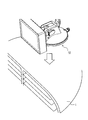
- FIG. 1 It is a figure which shows the state which attached the portable navigation apparatus of the Example to the dashboard of a motor vehicle using the suction cup stand. It is an internal block diagram of the portable navigation apparatus of an Example. The history table of the spectrum peak frequency hold
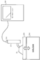
- FIG. 1 is a diagram illustrating a state in which the portable navigation device of the embodiment is attached to a dashboard of an automobile using a sucker stand.
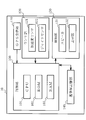
- FIG. 2 is an internal block diagram of the portable navigation device of the embodiment.
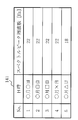
- FIG. 3 is a diagram illustrating a history table of spectrum peak frequencies held in the reference value storage unit of the portable navigation device of the embodiment.
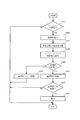
- FIG. 4 is a flowchart illustrating an operation of detecting the attachment state of the portable navigation device according to the embodiment.
- a suction cup stand 20 is attached to the upper surface of the dashboard 1 of the automobile.
- the portable navigation device 10 is attached to the suction cup stand 20.
- the sucker stand 20 includes a sucker portion that is attracted to the dashboard 1, a cradle portion (not shown) to which the portable navigation device 10 is attached and supported, a sucker portion, and a cradle portion. And a connecting portion that connects the two in a pivotable manner.
- the suction cup portion When the suction cup portion is adsorbed on the dashboard 1, it is held for a long time and the portable navigation device 10 can be supported at a fixed position. It is also possible to set the orientation of the portable navigation device 10 at a position where the user can easily see and operate by turning the connecting portion.
- the case where the portable navigation device 10 is attached to the dashboard 1 by the suction cup stand 20 is illustrated, but the present invention is not limited to this, and the stand is made of the double-sided adhesive tape and the dashboard 1 or the like. You may make it attach to the to-be-installed surface.
- the installation surface to be installed is not limited to the dashboard 1, and may be any position in the automobile.
- the portable navigation device 10 can be attached to and removed from the suction cup stand 20. And by attaching the portable navigation apparatus 10 to the suction cup stand 20 attached to the dashboard 1 (installed surface), the portable navigation device 10 is detachably attached to the installed surface (dashboard 1) by the stand (sucker stand 20).
- the portable navigation device 10 includes a control unit 100, a GPS receiving unit 110, a sensor unit 120, a notification unit 130, and a reference value storage unit 140.
- the control unit 100 is a processor that includes a CPU 101, a ROM 102, and a RAM 103.
- the CPU 101 executes a control program stored in the ROM 102 or the RAM 103 to control the operation of each unit of the portable car navigation device 10. Supervise.
- the controller 100 mainly performs (1) idling determination, (2) vibration analysis, (3) attachment state determination, and (4) notification control.
- (1) idling determination (2) vibration analysis
- (3) attachment state determination (3) attachment state determination
- (4) notification control (4) notification control.
- the control unit 100 complements the GPS positioning position output from the GPS receiving unit 110 based on the output from the sensor unit 120, and calculates the current position. If the calculated current position does not change for a predetermined time and the output of the acceleration sensor 121 and / or the gyro sensor 122 constituting the sensor unit 120 is equal to or less than a predetermined value, it is determined that the vehicle is idling. It is mentioned that the output of the acceleration sensor 121 and / or the gyro sensor 122 is equal to or less than a predetermined value as an idling determination condition, even when the occupant is getting on and off even when the automobile is not moving, etc. This is because the vehicle is not shaken and stabilized, and the attachment state of the suction cup stand 20 described below cannot be determined.
- the idling determination condition is not limited to the above. For example, idling is performed even when the GPS positioning position does not change for a predetermined time, or when the output of the acceleration sensor 121 and / or the gyro sensor 122 is equal to or less than a predetermined value. You may determine that it is in the state. Further, whether or not the key switch of the automobile is in the ON state (whether or not the engine is operating) may be added to the determination condition.
- the reason for determining whether or not the vehicle is idling is to compare the reference value with the extracted spectrum peak frequency in the mounting state determination process described later. Specifically, this is because the state where the reference value is stored (the state when the spectrum peak frequency serving as the reference value is extracted) and the state when the spectrum peak frequency is extracted are made the same state.
- vibration (acceleration, etc.) applied to the portable navigation device 10 varies depending on road noise and engine speed, so the idling state is determined, and only when the idling state is present. If the spectrum peak frequency is extracted, the spectrum peak frequency in the same state (same vibration applied to the suction cup stand 20) can be extracted. Then, the spectral peak frequency in the idling state is stored as a reference value, and the spectral peak frequency extracted in the idling state is compared with the reference value, so that an attachment state determination process described later is performed.
- the vibration applied to the suction cup stand 20 is the same. Even if it is not running, it may be running. Even in the idling state, the vibration applied to the suction cup stand 20 may be different depending on the operating state of the air conditioner, etc., so that the portable navigation device 10 is connected to the vehicle information (air conditioner operation) via a wired or wireless communication unit. If the state, engine speed, etc.) can be acquired, these pieces of information may be added to the idling determination condition.
- the idling state is determined when the output of the acceleration sensor 121 and / or the gyro sensor 122 is equal to or lower than a predetermined value.
- the present invention is applicable to a vehicle that automatically stops the engine when the vehicle stops. Therefore, two threshold values (a first threshold value for determining whether to stop and a second threshold value for determining engine operation) are provided, and the output of the sensor unit 120 (the acceleration sensor 121 and / or the gyro sensor 122) is When it is less than or equal to the first threshold and greater than or equal to the second threshold, it may be determined that the state is idling (idling state).
- the control part 100 samples the change of the vibration value (acceleration and / or angular velocity) of the portable navigation apparatus 10 output from the sensor part 120. Sampling is performed, for example, by recording vibration values (acceleration and / or angular velocity) for 10 seconds at a sampling frequency of 100 Hz. Moreover, the control part 100 decomposes
- frequency decomposition discrete Fourier transform
- the control unit 100 compares the spectrum peak frequency extracted in the vibration analysis process with a reference value that is a past spectrum peak frequency (history value) stored in the reference value storage unit 140. It is determined whether or not the difference is greater than a predetermined value. If the spectral peak frequency extracted in the vibration analysis process is more than a predetermined value away from the past spectral peak frequency, the control unit 100 determines that the suction cup stand 20 is in a swinging state before dropping from the dashboard 1, If it is less than the predetermined value, it is determined that the suction cup stand 20 is attached to the dashboard 1 without swinging.
- the reference value may be a spectrum peak frequency at a fixed time set in advance as a reference frequency in a template of the reference value storage unit 140 and stored. Further, the reference value may be set and stored in advance with the spectral peak frequency immediately before the stand is dropped as the reference frequency. When the spectral peak frequency immediately before the stand is dropped is preset and stored as a reference frequency, the mounting state is determined based on whether or not the extracted spectral peak frequency is within a predetermined value with respect to the reference frequency immediately before the stand is dropped.
- control unit 100 compares the amplitude value of the specific frequency among the vibration values subjected to frequency decomposition with the corresponding amplitude value (reference value) of the specific frequency stored in the reference value storage unit 140, and determines a predetermined value. You may make it determine the attachment state of the suction cup stand 20 by whether it changed more than the value.
- the reference value may be an amplitude value at a specific frequency in the past (when fixed) stored in the reference value storage unit 140, or may be a preset amplitude value at a specific frequency.
- the control unit 100 determines that the suction cup stand 20 is in a swinging state before dropping from the dashboard 1 in the above-described attachment state determination process, the portable navigation device 10 may be dropped.
- a message indicating that the message is present is generated and output to the notification unit 130.
- the notification unit 130 performs notification as a voice, for example, a warning message such as “There is a possibility that the installation of the stand is loose. Please attach it again” is generated and output to the notification unit 130.
- the notification unit 130 outputs a sound.
- the control unit 100 when the notification unit 130 performs notification as an image or video, the control unit 100 generates a display image or video of a similar warning message or outputs a display instruction to the notification unit 130, and the notification unit 130 displays the warning message. indicate.
- the message to be notified may be output to the notification unit 130 by combining sound, an image, and a video.
- control unit 100 when the control unit 100 outputs a notification to the notification unit 130, the control unit 100 holds that the notification has been performed as a flag, and after a predetermined time has elapsed, performs a mounting state determination process to again determine the mounting state. If it is determined that the swinging state is not the swinging state before dropping (the state where the swinging state is attached without swinging), a message such as “Fixed” may be output to the notification unit 130. Good.
- the GPS receiver 110 receives radio waves (satellite signals) including time information received from a plurality of GPS satellites orbiting the earth at predetermined time intervals, and based on this signal, position information (GPS positioning position) of the vehicle ) Is calculated.
- radio waves such as radio waves (satellite signals) including time information received from a plurality of GPS satellites orbiting the earth at predetermined time intervals, and based on this signal, position information (GPS positioning position) of the vehicle ) Is calculated.
- the sensor unit 120 includes an acceleration sensor 121 and a gyro sensor 122.
- the acceleration sensor 121 measures the acceleration applied to the portable navigation device 10 and outputs the measured value to the control unit 100.
- the gyro sensor 122 measures a change in angular velocity applied to the portable navigation device 10 and outputs the measured value to the control unit 100.
- the sensor unit 120 includes the acceleration sensor 121 and the gyro sensor 122.
- the present invention is not limited to this, and the sensor detects at least one of the displacement, speed, and acceleration of the portable navigation device 10. You may make it comprise by.
- control unit 100 calculates acceleration based on the output of the acceleration sensor 121 and the control unit 100 calculates angular velocity based on the output of the gyro sensor 122, until the acceleration or angular velocity is calculated (detected). It is preferable to use the acceleration sensor 121 and the gyro sensor 122 including the above processing.
- the notification unit 130 includes a speaker 131 and a display unit 132.
- the speaker 131 converts the sound output signal from the control unit 100 into sound and outputs the sound.
- the display unit 132 receives the warning message display image signal or the display instruction from the control unit 100 and displays the display image.
- the reference value storage unit 140 is composed of a storage medium, and stores a reference value for comparison in an attachment state determination process performed in the control unit 100.
- the reference value storage unit 140 is provided as a storage unit separate from the ROM 102 and RAM 103 of the control unit 100, but the present invention is not limited to this, and the reference value storage unit 140 is stored in the ROM 102 or RAM 103 of the control unit 100. It may be. That is, the ROM 102 and the RAM 103 may function as the reference value storage unit 140.
- the reference value is a spectrum peak frequency extracted by the control unit 100 in the past.
- the spectrum peak frequency is a frequency indicating the maximum amplitude among frequency components constituting the vibration when the vibration value is subjected to frequency decomposition.
- the reference value may be set and stored in advance at the time of shipment using the spectrum peak frequency when the portable navigation device 10 is stably fixed as a template.
- the reference value may be a value stored as a spectral peak frequency immediately before the suction cup stand 20 is dropped.
- the reference value may be an amplitude value at a specific frequency. Since these reference values differ depending on the model of the portable navigation device 10, the reference value of the corresponding model may be stored as a template at the time of shipment.
- the reference value also depends on the individual difference of the device or the orientation of the stand. Since historical values can change, using historical values can address these differences. Further, the reference value storage unit 140 may hold a history table 141 in which history values of spectrum peak frequencies are recorded. An example of the history table 141 is shown in FIG.
- the history table 141 includes the date and time when data (spectrum peak frequency) was recorded and the measured spectrum peak frequency.
- the data is stored as a plurality of histories, and may be updated by recording a new spectrum peak frequency at a predetermined period interval (each determination of the idling state), and the obsolete data may be discarded.
- the attachment state when performing the attachment state determination process using the history table 141 shown in FIG. 3, unless the immediately before data (for example, data No. 5 stored last) is used as a reference value, the attachment state does not change abruptly. It is conceivable that the reference value and the extracted spectrum peak frequency do not deviate by a predetermined value or more.
- the data (spectrum peak frequency) used as the reference value is preferably a predetermined time (for example, No2 data) or No1 data stored first.
- the reference value storage unit 140 holds the spectrum peak frequency for each location and material of the dashboard 1 as a template.
- the reference value may be selected and set by designating the attachment location when the user performs the initial setting. A template creation method will be described later.
- step S ⁇ b> 401 of FIG. 4 the control unit 100 calculates the current position by complementing the GPS positioning position calculated by the GPS receiving unit 110 based on the output from the sensor unit 120. By determining whether the calculated current position does not change for a predetermined time and whether the output of the acceleration sensor 121 and / or the gyro sensor 122 constituting the sensor unit 120 is below a predetermined value, the vehicle is stabilized. It is determined whether or not the vehicle is idling.
- the process is terminated because it is not suitable for determining the attachment state of the suction cup stand 20.
- step S402 the control unit 100 acquires the vibration value output from the acceleration sensor 121 and / or the gyro sensor 122.
- the acceleration (vibration value) output from the acceleration sensor 121 and / or the angular velocity value (vibration value) output from the gyro sensor 122 are sampled at a predetermined sampling frequency for a predetermined time, for example, at a sampling frequency of 100 Hz for 10 seconds. To do.
- the vibration value output from the acceleration sensor 121 and / or the gyro sensor 122 is acquired when it is determined that the automobile is in the idling state. Alternatively, it is acquired every time it is output from the gyro sensor 122.
- step S402 a vibration value from when it is determined that the automobile is in an idling state until a predetermined time (for example, 10 seconds) has passed may be acquired.
- the controller 100 determines whether or not the vehicle is in a stable idling state even after a predetermined time (for example, 10 seconds) has elapsed since it was determined that the vehicle is idling. It is not changed, and the determination of whether the output of the acceleration sensor 121 and / or the gyro sensor 122 constituting the sensor unit 120 is below a predetermined value is continuously performed until a predetermined time (for example, 10 seconds) elapses.
- a predetermined time for example, 10 seconds
- step S403 the control unit 100 decomposes the vibration values acquired and sampled in step S402 into frequency components by performing a discrete Fourier transform process.
- step S404 the control unit 100 extracts the frequency component having the largest amplitude among the frequency components constituting the vibration as the spectrum peak frequency.
- step S405 the control unit 100 refers to the reference value storage unit 140 and determines whether or not the reference value has already been stored in the reference value storage unit 140. If the reference value is not stored, the process proceeds to step S409, and the extracted spectrum peak frequency is stored in the reference value storage unit 140 as a reference value.
- the reference value may be a preset value stored in advance at the time of factory shipment (a spectrum peak frequency of vibration when the suction cup stand 20 is fixed), or a spectrum peak frequency previously extracted and stored. May be.
- step S405 when the reference value is already stored in the reference value storage unit 140, the process proceeds to step S406.
- step S ⁇ b> 406 the control unit 100 compares the extracted spectral peak frequency with the reference value stored in the reference value storage unit 140. If the spectrum peak frequency extracted by the control unit 100 in the past is used as the reference value, the extracted spectrum peak frequency is obtained even if the reference value is already stored in the reference value storage unit 140 in step S405. Is preferably stored in the reference value storage unit 140.
- step S407 the control unit 100 determines whether or not the extracted spectrum peak frequency is a predetermined value or more away from the reference value. If the extracted spectral peak frequency is not separated from the reference value by a predetermined value or more, it is determined that the suction cup stand 20 is firmly attached to the dashboard 1 (a state in which the sucker stand 20 is attached without swinging). End (you may notify that it is attached via a notification part). On the other hand, if the extracted spectral peak frequency is more than a predetermined value away from the reference value, it is determined that the suction cup stand 20 is in a state immediately before dropping from the dashboard 1 (swing state), and the process proceeds to step S408. This is, for example, when the reference value is 22 Hz, when the reference value is 4 Hz or more away from 22 Hz (when the extracted spectral peak frequency is 18 Hz), and the like. (Refer to the measurement results in FIG. 6)
- the processing from S402 to S404 may be performed, and the spectrum peak frequency extracted in step S404 may be stored as a reference value.
- step S ⁇ b> 408 the control unit 100 generates a message indicating that the portable navigation device 10 may fall, outputs the message to the notification unit 130, and outputs the voice from the speaker 131 of the notification unit 130 or the display unit 132. To output as an image, and the process ends.
- the message indicating the possibility of falling is a warning message such as “There is a possibility that the installation of the stand is loose. Please try again.” What is necessary is just to display a warning image.
- control part 100 hold
- the spectrum peak frequency is compared with the reference value, and if the swing state is not the swing state before dropping (the state where the swing state is installed without swinging), a message such as “Fixed” is notified. You may make it output via.
- the reference value is a spectrum peak frequency indicating that the suction cup stand 20 is firmly attached to the dashboard 1, and the spectrum peak frequency extracted from the measured vibration value with respect to this reference value.
- the attachment state of the suction cup stand 20 (whether or not it is in a swaying state) may be determined depending on how far the difference is.
- the reference value is a frequency immediately before the suction cup stand 20 drops off the dashboard 1, and the suction peak of the suction cup stand 20 depends on how close the spectral peak frequency extracted from the measured vibration value is to the reference value. You may make it determine an attachment state (whether it is a swaying state).
- the reference value may be an amplitude value at a specific frequency when the vibration value is subjected to frequency decomposition. In that case, the amplitude value of the specific frequency is extracted from the vibration value and compared with the reference value.
- FIG. 5 is a schematic diagram of a measuring device for presetting a reference value of the portable navigation device 10 of the embodiment.
- FIG. 6 is a diagram showing power spectra of the suction cup stand 20 and the portable navigation device 10 measured using the measuring device of FIG.
- the vibration testing machine 510 Prior to measurement of vibration value, the portable navigation device 10 is attached to the suction cup stand 20.
- the vibration testing machine 510 includes a vibration table 520.
- the suction cup stand 20 to which the portable navigation device 10 is connected is firmly attached to the upper surface of the vibration table 520.
- the acceleration pickup 530 is brought into close contact with the upper surface of the portable navigation device 10 and fixed with an adhesive or the like if necessary.
- the acceleration pickup 530 is connected to a G meter 540 (accelerometer) so that the vibration level detected by the acceleration pickup 530 can be measured by the G meter 540.
- the vibration test is performed by, for example, a method in which simple vibration in the vertical direction is applied to the mounting posture of the suction cup stand 20 and the portable navigation device 10, and the vibration frequency is between a minimum vibration frequency of 5 Hz and a maximum vibration frequency of 50 Hz.
- the vibration table 520 is vibrated while changing so as to reciprocate once in 10 seconds.
- the suction cup stand 20 to which the portable navigation device 10 is connected is attached to the upper surface of the vibration table 520 in a state before dropping, and the vibration test as described above is performed.
- the acceleration value for each frequency is extracted based on the acceleration value measured in the G meter 540, and a power spectrum as shown in FIG. 6 is obtained. Then, when the suction cup stand 20 is firmly attached, it can be seen that the spectrum peak frequency is about 22 Hz, and the spectrum peak frequency is 18 Hz in a state immediately before the suction cup stand 20 is removed. Therefore, the spectrum peak frequency in the fixed state of the suction cup stand 20 is stored in the reference value storage unit 140 as a preset reference value. Alternatively, the spectrum peak frequency in a state immediately before the suction cup stand 20 is dropped may be stored as a preset reference value.
- the reference value set in the reference value storage unit 140 may be an acceleration value at a specific frequency, for example, 22 Hz.
- the control unit 100 performs the attachment state determination process, if the acceleration value at 22 Hz is 0.87 G, it is determined that the attachment is firmly made, and how far away from this acceleration value (the sucker stand 20 is dropped) The degree of attachment of the suction cup stand 20 is determined based on how close it is to the previous acceleration value of 0.27G).
- an acceleration value at a specific frequency for example, 22 Hz
- the acceleration value increases or attenuates due to the slope of the slope when the vehicle is stopped on the slope. It is possible to do. Therefore, even in the idling state, it is preferable not to perform the attachment state processing on a slope. Whether it is a slope or not can be determined by various methods. For example, when map matching processing is performed based on GPS positioning position or map information (stored in a map storage unit (not shown)), slope information (gradient or the like) is included in the map information. ) Is included, it can be determined by referring to the gradient of the current position subjected to the map matching process.
- the suction cup stand 20 is exemplified as the stand, but a stand using a double-sided tape may be used.
- the portable navigation apparatus 10 was attached to the suction cup stand 20 without rocking
- the example which determines the attachment state to the to-be-installed surface (dashboard 1) of the suction cup stand 20 was shown. It is also possible to determine the attachment state of the portable navigation device 10 to the suction cup stand 20 by a similar method.
- the suction cup stand 20 is not attached to the installation surface (dashboard 1) without swinging, and the case where the portable navigation device 10 is It is conceivable that it is not attached to the suction cup stand 20 without swinging.
- the control unit 100 has a risk that the suction cup stand 20 may fall from the installation surface (dashboard 1), and the portable navigation device 10 moves from the suction cup stand 20.
- a message indicating that there is a risk of falling may be generated and output to the notification unit 130, and may be output as sound from the speaker 131 of the notification unit 130 or as an image from the display unit 132.
- the message indicating the possibility of falling is a warning message such as "There is a possibility that the stand is attached to the dashboard or the navigation is loose. Please attach it again.” Anything that broadcasts or displays a warning image such as “Confirmation of stand installation and navigation installation!” May be used.
- the control unit 100 when the suction cup stand 20 is attached to the installation surface (dashboard 1) without swinging (when fixed), the reference value and the extracted spectrum peak frequency are separated from each other by a predetermined value or more. This is a case where the portable navigation device 10 is not attached to the suction cup stand 20 without swinging. Therefore, for example, in the process of S408 in FIG. 4, the control unit 100 generates a message indicating that there is a risk that the portable navigation device 10 may fall from the suction cup stand 20, and outputs the message to the notification unit 130. The sound may be output from 130 speakers 131 or as an image from the display unit 132.
- the message indicating the possibility of dropping may be a warning message such as “The navigation may be loosely attached to the stand. Please try again.” Or a warning image such as “” may be displayed.
- the portable navigation device 10 is attached to the suction cup stand 20 without swinging (determination of the attachment state), and the portable navigation device 10 is attached to the suction cup stand 20 without swinging.
- the determination of whether or not (attachment state determination) and whether or not the suction cup stand 20 is attached to the installation surface (dashboard 1) without swinging (determination of attachment state) are described in the above embodiment. Any of the methods may be used.
- a message indicating the possibility of dropping is output via the notification unit 130, and then the mounting is performed.
- a message indicating that the risk of dropping has been eliminated is output via the notification unit 130. May be.
- the portable navigation device 10 and the suction cup stand 20 have different configurations, and the portable navigation device 10 can be detached from the suction cup stand 20, but the present invention is not limited to this.
- the navigation device 10 and the suction cup stand 20 may have an integrated configuration (configuration that cannot be removed).
- the present invention can also be applied to the portable navigation device 10 having an adhesive member (for example, the suction cup stand 20) that can be attached / detached to / from the dashboard 1 (surface to be installed).
- an adhesive member for example, the suction cup stand 20
- FIG. 7 illustrates a portable navigation device 10 having a sucker stand.
- the acceleration (vibration value) output from the acceleration sensor 121 and / or the angular velocity value (vibration value) output from the gyro sensor 122 are determined at a predetermined sampling frequency. Sampling time. Further, the sampled vibration value is subjected to discrete Fourier transform processing to be decomposed into frequency components, and among the frequency components constituting the vibration, the one having the largest amplitude is extracted as the spectrum peak frequency.
- the extracted spectral peak frequency is compared with the reference value, and if the extracted spectral peak frequency is separated from the reference value by a predetermined value or more, the state immediately before the portable navigation device 10 is dropped from the dashboard 1 (swing)
- a message indicating that the portable navigation device 10 may be dropped.
- the message for example, by outputting a message indicating the possibility of dropping (such as “attachment confirmation!”) As a sound from the speaker 131 of the notification unit 130 or as an image from the display unit 132, the portable navigation device 10 is dropped. It is possible to prevent it.
- the present invention can also be applied when a mechanism for detachably attaching the portable navigation device 10 to the dashboard 1 (installed surface) is provided.
- FIG. 8 includes a recess 801 into which the portable navigation device 10 is inserted into the dashboard 1 (installed surface) as an example of a mechanism for detachably attaching the portable navigation device 10.
- a protrusion 803 that moves in response to pressing of the detach button 802 (moves so that there is no protrusion) is illustrated.
- the portable navigation device 10 of FIG. 8 is provided with a recess 804 corresponding to the protrusion 803.
- the portable navigation device 10 is inserted into the recess 801 in a state in which the user attaches / removes the attachment / removal button 802. Then, when the attachment / detachment button 802 is not in the depressed state, the protrusion 803 is inserted into the recess 804 of the portable navigation device 10 and the portable navigation device 10 is attached to the dashboard 1 (installed surface).
- the portable navigation device 10 when the portable navigation device 10 is removed from the dashboard 1 (surface to be installed), the portable navigation device 10 is extracted from the recess 801 while the attachment / detachment button 802 is pressed, so that the portable navigation device 10 is removed. 10 is removed from the dashboard 1 (surface to be installed).
- the portable navigation device 10 is caused by vibration caused by traveling, unexpected pressure, or the like. May fall (drop off).
- the portable navigation device 10 is mounted as shown in the flowchart of FIG. It is determined whether or not the vehicle is idling. Then, when it is determined that the automobile is in an idling state, the acceleration (vibration value) output from the acceleration sensor 121 and / or the angular velocity value (vibration value) output from the gyro sensor 122 are determined at a predetermined sampling frequency. Sampling time. Further, the sampled vibration value is subjected to discrete Fourier transform processing to be decomposed into frequency components, and among the frequency components constituting the vibration, the one having the largest amplitude is extracted as the spectrum peak frequency.
- the extracted spectral peak frequency is compared with the reference value, and if the extracted spectral peak frequency is separated from the reference value by a predetermined value or more, the state immediately before the portable navigation device 10 is dropped from the dashboard 1 (swing)
- a message indicating that the portable navigation device 10 may be dropped.
- the message for example, by outputting a message indicating the possibility of dropping (such as “attachment confirmation!”) As a sound from the speaker 131 of the notification unit 130 or as an image from the display unit 132, the portable navigation device 10 is dropped. It is possible to prevent it.
- the portable navigation device 10 includes the control unit 100, the acceleration sensor 121, Although the case where it comprises the gyro sensor 122 etc. was illustrated, it is not restricted to this.
- the suction cup stand 20 (which may be a double-sided tape stand if removable) receives power from an automobile ACC power supply (from a cigar socket, etc.), (1) idling determination, and (2) vibration analysis. , (3) Mounting state determination, (4) Control unit 100 that performs notification control processing, acceleration sensor 121, gyro sensor 122, and the like.
- the suction cup stand 20 may determine whether or not the suction cup stand 20 attached to the dashboard 1 (installed surface) is likely to fall (drop off) from the dashboard 1.
- the control unit 100 included in the suction cup stand 20 determines whether or not the automobile on which the suction cup stand 20 is mounted is in an idling state. And when it determines with a motor vehicle being in an idling state, the value (vibration value) of the acceleration (vibration value) output from the acceleration sensor 121 with which the suction cup stand 20 is provided, and / or the angular velocity value (vibration value) output from the gyro sensor 122, Sampling is performed for a predetermined time at a predetermined sampling frequency. Further, the sampled vibration value is subjected to discrete Fourier transform processing to be decomposed into frequency components, and among the frequency components constituting the vibration, the one having the largest amplitude is extracted as the spectrum peak frequency.
- the extracted spectral peak frequency is compared with a reference value, and if the extracted spectral peak frequency is more than a predetermined value from the reference value, the state immediately before the suction cup stand 20 is dropped from the dashboard 1 (swing state) And a message indicating that the suction cup stand 20 may fall is generated.
- a message such as “installation confirmation !!”
- the suction cup stand 20 is removably attached to the portable navigation device 10 and is removably attached to the dashboard 1.
- the suction cup stand 20 includes a sensor unit 120 (acceleration sensor 121 and / or gyro sensor 122) and a wired or wireless communication unit (communication interface) for transmitting vibration values to the portable navigation device 10,
- the portable navigation device 10 may include a communication unit for receiving a vibration value transmitted from a communication unit included in the suction cup stand 20.
- control value of the portable navigation device 10 may acquire the vibration value applied to the suction cup stand 20 via the communication unit, and the attachment state of the suction cup stand 20 may be determined based on the acquired vibration value.
- the control unit 100 of the portable navigation device 10 is first mounted with the suction cup stand 20 based on the vibration value transmitted from the suction cup stand 20 acquired through the communication unit. It is determined whether or not the vehicle is idling. When it is determined that the vehicle is in an idling state, the acceleration (vibration value) output from the acceleration sensor 121 included in the suction cup stand 20 and transmitted from the communication unit and / or the gyro sensor 122 is output and transmitted from the communication unit. The value of the angular velocity (vibration value) is sampled at a predetermined sampling frequency for a predetermined time. Further, the sampled vibration value is subjected to discrete Fourier transform processing to be decomposed into frequency components, and among the frequency components constituting the vibration, the one having the largest amplitude is extracted as the spectrum peak frequency.
- the extracted spectral peak frequency is compared with a reference value, and if the extracted spectral peak frequency is more than a predetermined value from the reference value, the state immediately before the suction cup stand 20 is dropped from the dashboard 1 (swing state) And a message indicating that the suction cup stand 20 may fall is generated.
- a message for example, by outputting a message (such as “attachment confirmation!”) Indicating the possibility of dropping as a sound from the speaker 131 of the notification unit 130 provided in the portable navigation device 10 or as an image from the display unit 132, It is possible to prevent the suction cup stand 20 from falling off.
- the portable navigation device 10 and the suction cup stand 20 are provided with the notification unit 130, the reference value storage unit 140, and the GPS reception unit 110 is illustrated, but the present invention is not limited thereto.
- a communication device including the notification unit 130 may be provided separately, and the portable navigation device 10 or the suction cup stand 20 may include a communication unit for performing wired or wireless communication with the communication device.
- the control unit 100 included in the portable navigation device 10 or the suction cup stand 20 determines that the portable navigation device 10 or the suction cup stand 20 is about to fall (the extracted spectrum peak frequency is more than a predetermined value from the reference value). If so, generate a message indicating the possibility of falling.
- control part 100 may transmit an instruction
- the reference value storage unit 140 includes a communication device including the reference value storage unit 140, and the control unit 100 issues a recording instruction and a reference value read instruction to the reference value storage unit 140 of the communication device via the communication unit. You may go.
- the GPS receiving unit 110 may be provided with a communication device including the GPS receiving unit 110, and the control unit 100 may acquire the current position from the GPS receiving unit 110 of the communication device via the communication unit.
Landscapes
- Engineering & Computer Science (AREA)
- Mechanical Engineering (AREA)
- General Engineering & Computer Science (AREA)
- Fittings On The Vehicle Exterior For Carrying Loads, And Devices For Holding Or Mounting Articles (AREA)
Abstract
スタンドに取外し可能に取付けられる携帯型電子装置であって、前記携帯型電子装置は、基準値を記憶する基準値記憶部と、報知部と、前記携帯型電子装置に加わる振動値を検出するセンサ部と、前記振動値と前記基準値とに基づいて前記スタンドへの前記携帯型電子装置の取付け状態を判定し、前記取付け状態に基づく報知メッセージを前記報知部を介して出力する制御部と、を備えることとする。
Description
本発明は、被設置面に取付けられる携帯型電子装置及びスタンド、特に、携帯型電子装置又はスタンドに加わる振動の状態を判定することによって携帯型電子装置及び/又はスタンドの取付け状態を判定し、脱落しそうな場合に報知することで脱落防止を図る携帯型電子装置及びスタンドに関する。
携帯型のナビゲーション装置等の携帯型電子装置は、従来、スタンドによって自動車等のダッシュボード等に取外し可能に取付けられていた。スタンドは、通常、ねじや両面粘着テープ等によってダッシュボードに固定されていた。
ねじによってダッシュボードに固定されたスタンドは、一度固定すると、ねじを取外さなければダッシュボードから取外すことができず、スタンドを取外して移動させることは手間のかかる作業であった。また、両面粘着テープによって固定された場合も、一旦固定してしまった場合は、両面粘着テープを剥がしたりするのは手間がかかる。さらに、両面粘着テープをきれいに剥がすことができず、ダッシュボードに接着跡が残ってしまうこともあった。
そこで、下記特許文献1(特開2008-239100号公報)は、携帯型電子装置をダッシュボード等に固定するためのスタンドを、ねじや両面粘着テープに代えて、吸着面を有する吸盤を備える構成としている。吸盤を使用することによって、このスタンドを備える携帯型電子装置のダッシュボード等に対する取外し操作は簡単になる。従って、ユーザはスタンド(スタンドを備える携帯型電子装置)を所望の位置へ簡単に取付けることができるだけではなく、取付けられたスタンド(スタンドを備える携帯型電子装置)を取外すことや、取外されたスタンド(スタンドを備える携帯型電子装置)の取付け位置の移動を行うことが容易にできる。
ところで、両面粘着テープや吸盤が取付けられるダッシュボード等の被設置面は、自動車の走行時には定常的に振動にさらされるだけでなく、高温や低温にもさらされる。そのため、例えば、両面粘着テープや吸盤などの接着部材を使用してスタンドや携帯型電子装置をダッシュボード等の被設置面に取付けた場合、両面粘着テープや吸盤の吸着力は次第に弱くなり、或いは、予期せぬ加圧や経年変化により、スタンドや携帯型電子装置はある時点で取付けられた位置から脱落することがある。スタンドや携帯型電子装置が取付け箇所から脱落する(車内に落下する)と、スタンドや携帯型電子装置が損傷したり、スタンドや携帯型電子装置によって人体が傷つけられたり、運転に支障をきたしたりする恐れがある。
そこで、本発明の目的は、自動車のダッシュボード等の被設置面に取付けられる携帯型電子装置及びスタンドにおいて、被設置面への携帯型電子装置の取付け状態、若しくは被設置面へのスタンドの取付け状態、及び/又はスタンドへの携帯型電子装置の取付け状態を監視し、脱落しそうな状態であれば報知することによって、脱落防止を図ることである。
上記課題を解決するため本発明の携帯型電子装置は、スタンドに取外し可能に取付けられる携帯型電子装置であって、前記携帯型電子装置は、基準値を記憶する基準値記憶部と、報知部と、前記携帯型電子装置に加わる振動値を検出するセンサ部と、前記振動値と前記基準値とに基づいて前記スタンドへの前記携帯型電子装置の取付け状態を判定し、前記取付け状態に基づく報知メッセージを前記報知部を介して出力する制御部と、を備えることを特徴とする。
本発明の携帯型電子装置によれば、携帯型電子装置に加わる振動値、つまり、角速度や加速度を測定し、測定された振動値と基準値とを比較することによって携帯型電子装置がスタンドにしっかりと取付けられているかそれとも不安定な状態であるかを判定できるようになる。これにより、取付け状態を監視することが可能となり、必要な報知メッセージを出力することで脱落防止を図ることが可能となる。
上記課題を解決するため本発明の携帯型電子装置は、被設置面に取外し可能に取付けられる携帯型電子装置であって、前記携帯型電子装置は、前記携帯型電子装置に加わる振動値を検出するセンサ部と、前記振動値と基準値記憶部に記憶された基準値とに基づいて前記被設置面への前記携帯型電子装置の取付け状態を判定し、前記取付け状態に基づく報知メッセージを報知部を介して出力する制御部と、を備えることを特徴とする。
本発明の携帯型電子装置によれば、携帯型電子装置に加わる振動値、つまり、角速度や加速度を測定し、測定された振動値と基準値とを比較することによって携帯型電子装置が被設置面にしっかりと取付けられているかそれとも不安定な状態であるかを判定できるようになる。これにより、取付け状態を監視することが可能となり、必要な報知メッセージを出力することで脱落防止を図ることが可能となる。
上記課題を解決するため本発明の携帯型電子装置は、スタンドによって被設置面に取外し可能に取付けられる携帯型電子装置であって、前記携帯型電子装置は、基準値を記憶する基準値記憶部と、報知部と、前記携帯型電子装置に加わる振動値を検出するセンサ部と、前記振動値と前記基準値とに基づいて前記被設置面への前記スタンドの取付け状態を判定し、前記取付け状態に基づく報知メッセージを前記報知部を介して出力する制御部と、を備えることを特徴とする。
本発明の携帯型電子装置によれば、携帯型電子装置に加わる振動値、つまり、角速度や加速度を測定し、測定された振動値と基準値とを比較することによってスタンドが被設置面にしっかりと取付けられているかそれとも不安定な状態であるかを判定できるようになる。これにより、取付け状態を監視することが可能となり、必要な報知メッセージを出力することで脱落防止を図ることが可能となる。
上記課題を解決するため本発明の携帯型電子装置は、被設置面に取外し可能に取付けられるスタンドに取外し可能に取付けられる携帯型電子装置であって、前記携帯型電子装置は、前記スタンドが備えるセンサ部が検出する前記スタンドに加わる振動値を取得し、前記振動値と基準値記憶部に記憶された基準値とに基づいて前記被設置面への前記スタンドの取付け状態を判定し、前記取付け状態に基づく報知メッセージを報知部を介して出力する制御部を備えることを特徴とする。
本発明の携帯型電子装置によれば、スタンドに加わる振動値、つまり、角速度や加速度を測定し、測定された振動値と基準値とを比較することによってスタンドが被設置面にしっかりと取付けられているかそれとも不安定な状態であるかを判定できるようになる。これにより、取付け状態を監視することが可能となり、必要な報知メッセージを出力することで脱落防止を図ることが可能となる。
上記課題を解決するため本発明の携帯型電子装置は、スタンドによって被設置面に取外し可能に取付けられる携帯型電子装置であって、前記携帯型電子装置は、基準値を記憶する基準値記憶部と、報知部と、前記携帯型電子装置に加わる振動値を検出するセンサ部と、前記振動値と前記基準値とに基づいて前記被設置面への前記スタンドの取付け状態及び前記スタンドへの前記携帯型電子装置の取付け状態を判定し、前記取付け状態に基づく報知メッセージを前記報知部を介して出力する制御部と、を備えることを特徴とする。
本発明の携帯型電子装置によれば、携帯型電子装置に加わる振動値、つまり、角速度や加速度を測定し、測定された振動値と基準値とを比較することによってスタンドが被設置面にしっかりと取付けられているかそれとも不安定な状態であるか及び携帯型電子装置がスタンドにしっかりと取付けられているかそれとも不安定な状態であるかを判定できるようになる。これにより、取付け状態を監視することが可能となり、必要な報知メッセージを出力することで脱落防止を図ることが可能となる。
上記課題を解決するため本発明のスタンドは、携帯型電子装置が取外し可能に取付けられ、且つ、被設置面に取外し可能に取付けられるスタンドであって、前記スタンドは、前記スタンドに加わる振動値を検出するセンサ部と、前記振動値と基準値記憶部に記憶された基準値とに基づいて前記被設置面への前記スタンドの取付け状態を判定し、前記取付け状態に基づく報知メッセージを報知部を介して出力する制御部と、を備えることを特徴とする。
本発明のスタンドによれば、スタンドに加わる振動値、つまり、角速度や加速度を測定し、測定された振動値と基準値とを比較することによってスタンドが被設置面にしっかりと取付けられているかそれとも不安定な状態であるかを判定できるようになる。これにより、取付け状態を監視することが可能となり、必要な報知メッセージを出力することで脱落防止を図ることが可能となる。
また、本発明の携帯型電子装置又はスタンドにおいて、前記制御部は、前記センサ部により検出された振動値を周波数分解し、前記周波数分解した振動値と前記基準値とに基づいて前記取付け状態を判定することが望ましい。
これにより、周波数分解された振動値と基準値とに基づいて取付け状態を判定することが可能となる。
また、本発明の携帯型電子装置又はスタンドにおいて、前記基準値は、基準周波数であり、前記制御部は、前記周波数分解した振動値からスペクトルピーク周波数を算出し、前記基準周波数と前記スペクトルピーク周波数とを比較することにより、前記取付け状態を判定することが望ましい。
これにより、周波数分解された振動値と基準値とに基づいて取付け状態を判定することが可能となる。
また、本発明の携帯型電子装置において、前記制御部は、前記振動値と前記基準値とに基づいて前記携帯型電子装置が遥動なく前記スタンドに取付けられているか否かを判定し、前記携帯型電子装置が遥動なく前記スタンドに取付けられていないと判定した場合に、前記携帯型電子装置の脱落の危険性を示す報知メッセージを前記報知部を介して出力することが望ましい。
これにより、携帯型電子装置が遥動なくしっかりとスタンドに取付けられているか否かを判定し、遥動なくスタンドに取付けられていない場合には、携帯型電子装置の脱落の危険を示す報知メッセージを出力する。これにより、携帯型電子装置の取付けをユーザに促し、携帯型電子装置の脱落防止を図ることが可能となる。
また、本発明の携帯型電子装置において、前記制御部は、前記振動値と前記基準値とに基づいて前記携帯型電子装置が遥動なく前記被設置面に取付けられているか否かを判定し、前記携帯型電子装置が遥動なく前記被設置面に取付けられていないと判定した場合に、前記携帯型電子装置の脱落の危険性を示す報知メッセージを前記報知部を介して出力することが望ましい。
これにより、携帯型電子装置が遥動なくしっかりと被設置面に取付けられているか否かを判定し、遥動なく被設置面に取付けられていない場合には、携帯型電子装置の脱落の危険を示す報知メッセージを出力する。これにより、携帯型電子装置の取付けをユーザに促し、携帯型電子装置の脱落防止を図ることが可能となる。
また、本発明の携帯型電子装置において、前記制御部は、前記振動値と前記基準値とに基づいて前記スタンドが遥動なく前記被設置面に取付けられているか否かを判定し、前記スタンドが遥動なく前記被設置面に取付けられていないと判定した場合に、前記スタンドの脱落の危険性を示す報知メッセージを前記報知部を介して出力することが望ましい。
これにより、スタンドが遥動なくしっかりと被設置面に取付けられているか否かを判定し、遥動なく被設置面に取付けられていない場合には、スタンドの脱落の危険を示す報知メッセージを出力する。これにより、スタンドの取付けをユーザに促し、スタンドの脱落防止を図ることが可能となる。
また、本発明の携帯型電子装置又はスタンドにおいて、前記携帯型電子装置又は前記スタンドが取付けられる被設置面(前記被設置面)は自動車に設けられており、前記制御部は前記自動車がアイドリング状態か否かを判定し、前記自動車がアイドリング状態である場合に前記センサ部により検出された振動値と前記基準値とに基づいて前記取付け状態を判定することを特徴とする。
これにより、自動車の走行時等の不安定状態ではなく安定した状態のときに取付け状態を判定することが可能となり、取付け状態の判定を精度よく行うことが可能となる。
また、本発明のスタンドにおいて、前記制御部は、前記振動値と前記基準値とに基づいて前記スタンドが遥動なく前記被設置面に取付けられているか否かを判定し、前記スタンドが遥動なく前記被設置面に取付けられていないと判定した場合に、前記スタンドの脱落の危険性を示す報知メッセージを前記報知部を介して出力することが望ましい。
これにより、スタンドが遥動なくしっかりと被設置面に取付けられているか否かを判定し、遥動なく被設置面に取付けられていない場合には、スタンドの脱落の危険を示す報知メッセージを出力する。これにより、スタンドの取付けをユーザに促し、スタンドの脱落防止を図ることが可能となる。
上記課題を解決するため本発明の携帯型電子装置の落下防止方法は、スタンドに取外し可能に取付けられる携帯型電子装置の落下防止方法であって、前記携帯型電子装置に加わる振動値を検出するステップと、前記振動値と基準値記憶部に記憶された基準値とに基づいて前記スタンドへの前記携帯型電子装置の取付け状態を判定するステップと、前記取付け状態に基づく報知メッセージを報知部を介して出力するステップと、を有することを特徴とする。
上記課題を解決するため本発明の携帯型電子装置の落下防止方法は、被設置面に取外し可能に取付けられる携帯型電子装置の落下防止方法であって、前記携帯型電子装置に加わる振動値を検出するステップと、前記振動値と基準値記憶部に記憶された基準値とに基づいて前記被設置面への前記携帯型電子装置の取付け状態を判定するステップと、前記取付け状態に基づく報知メッセージを報知部を介して出力するステップと、を有することを特徴とする。
上記課題を解決するため本発明の携帯型電子装置の落下防止方法は、スタンドによって被設置面に取外し可能に取付けられる携帯型電子装置の落下防止方法であって、前記携帯型電子装置に加わる振動値を検出するステップと、前記振動値と基準値記憶部に記憶された基準値とに基づいて前記被設置面への前記スタンドの取付け状態を判定するステップと、前記取付け状態に基づく報知メッセージを報知部を介して出力するステップと、を有することを特徴とする。
上記課題を解決するため本発明の携帯型電子装置の落下防止方法は、被設置面に取外し可能に取付けられるスタンドに取外し可能に取付けられる携帯型電子装置の落下防止方法であって、前記スタンドに加わる振動値を取得するステップと、前記振動値と基準値記憶部に記憶された基準値とに基づいて前記被設置面への前記スタンドの取付け状態を判定するステップと、前記取付け状態に基づく報知メッセージを報知部を介して出力するステップと、を有することを特徴とする。
上記課題を解決するため本発明の携帯型電子装置の落下防止方法は、スタンドによって被設置面に取外し可能に取付けられる携帯型電子装置の落下防止方法であって、前記携帯型電子装置に加わる振動値を検出するステップと、前記振動値と基準値記憶部に記憶された基準値とに基づいて前記被設置面への前記スタンドの取付け状態及び前記スタンドへの前記携帯型電子装置の取付け状態を判定するステップと、前記取付け状態に基づく報知メッセージを報知部を介して出力するステップと、を有することを特徴とする。
上記課題を解決するため本発明のスタンドの落下防止方法は、携帯型電子装置が取外し可能に取付けられ、且つ、被設置面に取外し可能に取付けられるスタンドの落下防止方法であって、前記スタンドに加わる振動値を検出するステップと、前記振動値と基準値記憶部に記憶された基準値とに基づいて前記被設置面への前記スタンドの取付け状態を判定するステップと、前記取付け状態に基づく報知メッセージを報知部を介して出力するステップと、を有することを特徴とする。
本発明の携帯型電子装置及びスタンドによれば、携帯型電子装置又はスタンドに加わる振動値、つまり、角速度や加速度を測定し、測定された振動値と基準値とを比較することによって携帯型電子装置がスタンドにしっかりと取付けられているかそれとも不安定な状態であるか若しくは/及びスタンドが被設置面にしっかりと取付けられているかそれとも不安定な状態であるか、又は、携帯型電子装置が被設置面にしっかりと取付けられているかそれとも不安定な状態であるかを判定できるようになる。これにより、取付け状態を監視することが可能となり、必要な報知メッセージを出力することで携帯型電子装置及び/又はスタンドの脱落防止を図ることが可能となる。
以下、本願発明を実施するための最良の形態を実施例と共に図面を参照して詳細に説明する。ただし、以下に示す実施例は、本発明の技術思想を具体化するための携帯型電子装置として携帯型ナビゲーション装置を例示して説明するものであって、本発明をこの携帯型ナビゲーション装置に特定することを意図するものではなく特許請求の範囲に示した技術思想を逸脱することなくその他の携帯型電子装置にも等しく適用し得るものである。
図1~4を参照して、実施例の携帯型ナビゲーション装置における取付け状態の検出動作について説明する。図1は、実施例の携帯型ナビゲーション装置を、吸盤スタンドを使用して自動車のダッシュボードに取付けた状態を示す図である。図2は、実施例の携帯型ナビゲーション装置の内部ブロック図である。図3は、実施例の携帯型ナビゲーション装置の基準値記憶部に保持されるスペクトルピーク周波数の履歴テーブルを示す図である。図4は、実施例の携帯型ナビゲーション装置の取付け状態の検出動作を示すフローチャートである。
図1に示すように、自動車のダッシュボード1の上面には、吸盤スタンド20が取付けられている。吸盤スタンド20には携帯型ナビゲーション装置10が取付けられている。詳細な説明は省略するが、吸盤スタンド20は、ダッシュボード1に吸着される吸盤部分と、携帯型ナビゲーション装置10が取付けられて支持するクレードル部分(図示せず)と、吸盤部分とクレードル部分とを旋回可能に接続する接続部分とから構成される。
吸盤部分はダッシュボード1上に吸着されると、その箇所に長時間保持され、携帯型ナビゲーション装置10を定位置に支持することが可能となる。また、接続部分を旋回させることによって携帯型ナビゲーション装置10の向きをユーザが視認や操作しやすい位置に設定することも可能である。なお、本実施例では、携帯型ナビゲーション装置10が吸盤スタンド20によってダッシュボード1に取付けられた場合を例示しているが、本発明はこれに限られず、スタンドが両面粘着テープによってダッシュボード1等の被設置面に取付けられるようにしておいてもよい。また、設置される被設置面は、ダッシュボード1に限られず、自動車内の任意の位置であればよい。
なお、携帯型ナビゲーション装置10は、吸盤スタンド20への取付け及び吸盤スタンド20からの取外しが可能である。そして、携帯型ナビゲーション装置10をダッシュボード1(被設置面)に取付けられた吸盤スタンド20へ取付けることで、スタンド(吸盤スタンド20)によって被設置面(ダッシュボード1)に取外し可能に取付けられる。
図2に示すように、携帯型ナビゲーション装置10は、制御部100、GPS受信部110、センサ部120、報知部130、基準値記憶部140を備えて構成される。制御部100は、CPU101、ROM102、RAM103を備えて構成されるプロセッサであり、ROM102又はRAM103に記憶された制御プログラムをCPU101において実行することによって本携帯型カーナビゲーション装置10の各部の動作を制御・統括する。
本実施例において、制御部100は主に、(1)アイドリング判定、(2)振動解析、(3)取付け状態判定、(4)報知制御、の処理を行う。以下、各処理について説明する。
(1)アイドリング判定
制御部100は、GPS受信部110から出力されたGPS測位位置を、センサ部120からの出力に基づいて補完し、現在位置を算出する。算出した現在位置が所定時間変化せず、センサ部120を構成する加速度センサ121及び/又はジャイロセンサ122の出力が所定値以下の場合には、自動車がアイドリングしている状態であると判定する。アイドリングの判定条件として、加速度センサ121及び/又はジャイロセンサ122の出力が所定値以下であることが挙げられているのは、自動車が移動していないとしても、乗車人が乗り降りしているとき等は自動車が揺れて安定せず、以下で説明する吸盤スタンド20の取付け状態の判定を行うことができないためである。
制御部100は、GPS受信部110から出力されたGPS測位位置を、センサ部120からの出力に基づいて補完し、現在位置を算出する。算出した現在位置が所定時間変化せず、センサ部120を構成する加速度センサ121及び/又はジャイロセンサ122の出力が所定値以下の場合には、自動車がアイドリングしている状態であると判定する。アイドリングの判定条件として、加速度センサ121及び/又はジャイロセンサ122の出力が所定値以下であることが挙げられているのは、自動車が移動していないとしても、乗車人が乗り降りしているとき等は自動車が揺れて安定せず、以下で説明する吸盤スタンド20の取付け状態の判定を行うことができないためである。
なお、アイドリングの判定条件としては、上記に限ることはなく、例えば、GPS測位位置が所定時間変化しない場合、或いは、加速度センサ121及び/又はジャイロセンサ122の出力が所定値以下の場合のみでもアイドリングしている状態であると判定してもよい。また、自動車のキースイッチがON状態であるか否か(エンジン動作中か否か)を判定条件に加えてもよい。
なお、自動車がアイドリングしている状態であるか否かを判定する理由は、後述する取付け状態判定処理において、基準値と抽出したスペクトルピーク周波数とを比較するためである。具体的には、基準値を記憶した状態(基準値となるスペクトルピーク周波数を抽出したときの状態)と、スペクトルピーク周波数を抽出したときの状態を同一の状態とするためである。
すなわち、自動車が走行中では、路面ノイズやエンジンの回転数により、携帯型ナビゲーション装置10(吸盤スタンド20)に加わる振動(加速度等)が異なるため、アイドリング状態を判定し、アイドリング状態のときのみ、スペクトルピーク周波数を抽出すれば、同一の状態(吸盤スタンド20に加わる振動が同じ)ときのスペクトルピーク周波数を抽出できる。そして、アイドリング状態のときのスペクトルピーク周波数を基準値として記憶し、また、アイドリング状態のときに抽出したスペクトルピーク周波数を上記基準値と比較することで、後述する取付け状態判定処理が行なわれる。
なお、上記の通り、基準値と今回抽出したスペクトルピーク周波数が同一の状態(吸盤スタンド20に加わる振動が同じ)のときに抽出されたものであればよいため、同一の状態と判定できれば、アイドリングしている状態でなくても、走行中であってもよい。また、アイドリング状態であっても、エアコンの作動状態などにより吸盤スタンド20に加わる振動が異なることが考えられるため、携帯型ナビゲーション装置10が有線又は無線の通信部を介して、自動車情報(エアコン作動状態、エンジン回転数など)を取得できる場合は、これらの情報をアイドリングの判定条件に加えてもよい。
また、上記では、加速度センサ121及び/又はジャイロセンサ122の出力が所定値以下の場合に、アイドリング状態と判定することを記載したが、自動車の停止に伴いエンジンを自動的に停止させる自動車に対応するため、閾値を2つ(停車判定のための第1の閾値、及び、エンジン動作判定のための第2の閾値)設け、センサ部120(加速度センサ121及び/又はジャイロセンサ122)の出力が、第1の閾値以下であり、且つ、第2の閾値以上であるときに、アイドリングしている状態(アイドリング状態)であると判定してもよい。
(2)振動解析
制御部100は、センサ部120から出力された携帯型ナビゲーション装置10の振動値(加速度及び/又は角速度)の変化を、サンプリングする。サンプリングは、例えば、サンプリング周波数100Hzで10秒間にわたって振動値(加速度及び/又は角速度)を記録することにより行われる。また、制御部100は検出された振動値を周波数分解(離散フーリエ変換)することによって、検出された振動値を各周波数成分に分解する。そして、制御部100は周波数分解された各周波数の振動値の中から最大の振幅を示すスペクトルピーク周波数を抽出する。
制御部100は、センサ部120から出力された携帯型ナビゲーション装置10の振動値(加速度及び/又は角速度)の変化を、サンプリングする。サンプリングは、例えば、サンプリング周波数100Hzで10秒間にわたって振動値(加速度及び/又は角速度)を記録することにより行われる。また、制御部100は検出された振動値を周波数分解(離散フーリエ変換)することによって、検出された振動値を各周波数成分に分解する。そして、制御部100は周波数分解された各周波数の振動値の中から最大の振幅を示すスペクトルピーク周波数を抽出する。
(3)取付け状態判定
制御部100は、上記の振動解析処理において抽出したスペクトルピーク周波数と、基準値記憶部140に記憶された過去のスペクトルピーク周波数(履歴値)である基準値とを比較し、所定値以上異なるか否かを判定する。振動解析処理において抽出したスペクトルピーク周波数が過去のスペクトルピーク周波数から所定値以上離れているなら、制御部100は、吸盤スタンド20がダッシュボード1から落下する前の遥動状態であると判定し、所定値未満であれば、吸盤スタンド20は遥動なくダッシュボード1に取付けられていると判断する。
制御部100は、上記の振動解析処理において抽出したスペクトルピーク周波数と、基準値記憶部140に記憶された過去のスペクトルピーク周波数(履歴値)である基準値とを比較し、所定値以上異なるか否かを判定する。振動解析処理において抽出したスペクトルピーク周波数が過去のスペクトルピーク周波数から所定値以上離れているなら、制御部100は、吸盤スタンド20がダッシュボード1から落下する前の遥動状態であると判定し、所定値未満であれば、吸盤スタンド20は遥動なくダッシュボード1に取付けられていると判断する。
なお、基準値は、固定時におけるスペクトルピーク周波数を、基準値記憶部140のテンプレートに基準周波数として予め設定し記憶したものであってもよい。また、基準値は、スタンドの落下直前のスペクトルピーク周波数を基準周波数として予め設定記憶したものであってもよい。スタンドの落下直前のスペクトルピーク周波数を基準周波数として予め設定記憶する場合には、この落下直前の基準周波数に対し抽出したスペクトルピーク周波数が所定値以内に近づいたか否かで取付け状態を判定する。
さらに、制御部100は、周波数分解された振動値のうち、特定の周波数の振幅値を、基準値記憶部140に記憶された対応する特定の周波数の振幅値(基準値)と比較し、所定値以上変化したか否かで吸盤スタンド20の取付け状態を判定するようにしてもよい。基準値は、基準値記憶部140に記憶された過去の(固定時の)特定周波数における振幅値であってもよいし、特定周波数における予め設定された振幅値であってもよい。
(4)報知制御
制御部100は、上記の取付け状態判定処理において吸盤スタンド20がダッシュボード1から落下する前の遥動状態であると判断した場合に、携帯型ナビゲーション装置10の落下可能性があることを示すメッセージを生成し、報知部130に出力する。報知部130において音声として報知を行う場合、例えば、「スタンドの取付けが緩んでいる可能性があります。再度、付け直しをしてください。」といった警告メッセージを生成して報知部130に出力し、報知部130が音声出力する。
制御部100は、上記の取付け状態判定処理において吸盤スタンド20がダッシュボード1から落下する前の遥動状態であると判断した場合に、携帯型ナビゲーション装置10の落下可能性があることを示すメッセージを生成し、報知部130に出力する。報知部130において音声として報知を行う場合、例えば、「スタンドの取付けが緩んでいる可能性があります。再度、付け直しをしてください。」といった警告メッセージを生成して報知部130に出力し、報知部130が音声出力する。
制御部100は、また、報知部130において画像や映像として報知を行う場合は、同様の警告メッセージの表示画像や映像を生成又は表示指示を報知部130に出力し、報知部130は警告メッセージを表示する。なお、報知すべきメッセージは音声と画像や映像を組み合わせて報知部130に出力するようにしてもよい。
また、制御部100は、報知部130に対して報知出力を行った場合に、報知を行なったことをフラグとして保持しておき、所定時間経過後に、取付け状態判定処理を行って再度取付け状態を判定し、遥動状態が落下する前の遥動状態ではない(遥動なく取付けられている状態である)場合には、「直りました」といったメッセージを報知部130に出力するようにしてもよい。
GPS受信部110は所定の時間間隔で地球上空を周回している複数のGPS衛星から受信する時刻情報を含む電波(衛星信号)を受信し、この信号に基づいて自動車の位置情報(GPS測位位置)を算出する。
センサ部120は、加速度センサ121とジャイロセンサ122を備えて構成される。加速度センサ121は携帯型ナビゲーション装置10に加わる加速度を測定し、その測定値を制御部100に出力する。ジャイロセンサ122は携帯型ナビゲーション装置10に加わる角速度の変化を測定し、その測定値を制御部100に出力する。なお、本実施例では、センサ部120を加速度センサ121とジャイロセンサ122によって構成したが、本発明はこれに限られず、携帯型ナビゲーション装置10の変位、速度、加速度の少なくとも一つを検出するセンサによって構成するようにしてもよい。
また、加速度センサ121の出力に基づいて制御部100が加速度を算出し、ジャイロセンサ122の出力に基づいて制御部100が角速度を算出するような場合では、加速度や角速度を算出(検出)するまでの処理を含めて加速度センサ121やジャイロセンサ122とすることが好ましい。
報知部130は、スピーカ131と表示部132を備えて構成される。スピーカ131は、制御部100からの音声出力信号を音声に変換して出力する。表示部132は、制御部100からの警告メッセージ表示画像信号又は表示指示を受けて、表示画像を表示する。
基準値記憶部140は、記憶媒体で構成され、制御部100において行われる取付け状態判定処理において比較するための基準値が記憶される。本実施例において、基準値記憶部140は制御部100のROM102、RAM103とは別個の記憶手段として設けられているが、本発明はこれに限られず、制御部100のROM102やRAM103に記憶させるようにしてもよい。すなわち、ROM102やRAM103が基準値記憶部140として機能してもよい。
基準値は過去に制御部100により抽出されたスペクトルピーク周波数である。スペクトルピーク周波数とは、振動値を周波数分解した際に、その振動を構成する各周波数成分のうち最大の振幅を示す周波数のことである。また、基準値は、携帯型ナビゲーション装置10の安定した固定時におけるスペクトルピーク周波数をテンプレートとして出荷時に予め設定し、記憶したものでもよい。或いは、基準値は、吸盤スタンド20の落下直前のスペクトルピーク周波数を記憶したものであってもよい。又は、基準値は特定の周波数における振幅値であってもよい。これらの基準値は携帯型ナビゲーション装置10の機種毎に異なるので、出荷時に該当する機種の基準値をテンプレートとして記憶しておいてもよいが、装置の固体差やスタンドの向きによっても基準値が変化する場合があるので、履歴値を使用すると、それらの相違に対処できる。また、基準値記憶部140は、スペクトルピーク周波数の履歴値を記録した履歴テーブル141を保持してもよい。履歴テーブル141の一例を、図3に示す。
図3に示すように、履歴テーブル141は、データ(スペクトルピーク周波数)が記録された日時と、測定されたスペクトルピーク周波数で構成されている。データは複数履歴として保持されており、所定期間間隔(アイドリング状態の判定毎)で新しいスペクトルピーク周波数を記録することによって更新され、古くなったデータは破棄されるようにしてもよい。
なお、図3に示す履歴テーブル141を用いて取付け状態判定処理を行なう場合、直前のデータ(例えば、最後に記憶されたNo5のデータ)を基準値として用いると急激に取付け状態が変化しない限り、基準値と抽出したスペクトルピーク周波数が所定値以上離れないことが考えられる。
そのため、履歴テーブル141を用いて取付け状態判定処理を行なう場合、基準値として用いるデータ(スペクトルピーク周波数)は、所定時間前(例えば、No2のデータ)或いは、最初に記憶したNo1のデータが好ましい。
さらに、吸盤スタンド20を取付けるダッシュボード1の材質や場所によっても振動の状態が異なるので、基準値記憶部140には、ダッシュボード1の取付け箇所や材質毎のスペクトルピーク周波数をテンプレートとして保持しておき、ユーザが初期設定を行う際に取付け箇所を指定することで、基準値を選択設定できるようにしてもよい。なお、テンプレートの作成方法については後述する。
上記に説明した携帯型ナビゲーション装置10における吸盤スタンド20の取付け状態の検出動作を、図4を参照して説明する。図4のステップS401において、制御部100は、GPS受信部110によって算出されたGPS測位位置を、センサ部120からの出力に基づいて補完することによって現在位置を算出する。算出した現在位置が所定時間変化せず、また、センサ部120を構成する加速度センサ121及び/又はジャイロセンサ122の出力が所定値以下にあるか否かを判定することで、自動車が安定してアイドリングしている状態であるか否かを判定する。
現在位置が変化している場合や、加速度センサ121及び/又はジャイロセンサ122の出力が所定値より大きい場合には、自動車は走行中か、或いはアイドリングしているとしても乗降中等の自動車が揺れていて安定していない状態であるため、吸盤スタンド20の取付け状態を判定するのには不適であるために処理を終了する。
現在位置が変化しておらず、加速度センサ121及び/又はジャイロセンサ122の出力が所定値以下の場合には、自動車はアイドリング状態にあると判定され、ステップS402の処理に進む。
ステップS402において、制御部100は、加速度センサ121及び/又はジャイロセンサ122から出力される振動値を取得する。そして、加速度センサ121から出力された加速度(振動値)及び/又はジャイロセンサ122から出力された角速度の値(振動値)を、所定サンプリング周波数で所定時間、例えば、サンプリング周波数100Hzで10秒間、サンプリングする。
なお、本フローチャートでは、自動車がアイドリング状態にあると判定した場合に、加速度センサ121及び/又はジャイロセンサ122から出力される振動値を取得すると説明したが、制御部100は、加速度センサ121及び/又はジャイロセンサ122から出力される度に取得している。
すなわち、ステップS402では、自動車がアイドリング状態にあると判定してから所定時間(例えば10秒)経つまでの間の振動値を取得すればよい。
なお、自動車がアイドリング状態にあると判定してから所定時間(例えば10秒)経つまでの間も、制御部100は、自動車が安定してアイドリングしている状態であるか否か(現在位置が変化せず、また、センサ部120を構成する加速度センサ121及び/又はジャイロセンサ122の出力が所定値以下にあるか否か)の判定を継続して行い、所定時間(例えば10秒)経つまでに自動車がアイドリング状態でなくなると(現在位置が変化する、或いは、加速度センサ121及び/又はジャイロセンサ122の出力が所定値以上になると)、ステップS403の処理に進まないことが好ましい。
ステップS403において、制御部100は、ステップS402において取得・サンプリングした振動値を離散フーリエ変換処理することによって各周波数成分に分解する。
ステップS404において、制御部100は、振動を構成する各周波数成分のうち、もっとも振幅の大きいものをスペクトルピーク周波数として抽出する。
ステップS405において、制御部100は基準値記憶部140を参照し、基準値記憶部140に基準値が既に記憶されていたか否かを判定する。基準値が記憶されていなければステップS409の処理に進み、抽出したスペクトルピーク周波数を基準値として基準値記憶部140に記憶させる。なお、基準値は、工場出荷時に予め記憶された設定値(吸盤スタンド20の固定状態のときの振動のスペクトルピーク周波数)であってもよいし、以前に抽出し記憶させたスペクトルピーク周波数であってもよい。
ステップS405において、基準値記憶部140に基準値が既に記憶されている場合、ステップS406の処理に進む。ステップS406において、制御部100は抽出したスペクトルピーク周波数と基準値記憶部140に記憶された基準値とを比較する。なお、基準値として過去に制御部100により抽出されたスペクトルピーク周波数を用いる場合であれば、ステップS405において、基準値記憶部140に基準値が既に記憶されている場合でも、抽出したスペクトルピーク周波数を基準値記憶部140に記憶させることが好ましい。
ステップS407において、制御部100は、抽出したスペクトルピーク周波数が基準値から所定値以上離れているか否かを判定する。抽出したスペクトルピーク周波数が基準値から所定値以上離れていない場合、吸盤スタンド20がダッシュボード1にしっかりと取付けられている状態(遥動なく取付けられている状態)であると判断し、処理を終了する(取付けられていることを報知部を介して報知してもよい)。一方、抽出したスペクトルピーク周波数が基準値から所定値以上離れた場合、吸盤スタンド20がダッシュボード1から脱落する直前の状態である(遥動状態)と判断し、ステップS408の処理に進む。これは、例えば、基準値が22Hzである場合、22Hzから4Hz以上離れた場合(抽出したスペクトルピーク周波数が18Hzであった場合)等である。(図6の測定結果参照)
なお、基準値として過去に制御部100により抽出されたスペクトルピーク周波数を用いる場合であれば、上述した通り、所定時間(又は所定回数)前に抽出されたスペクトルピーク周波数を用いることが好ましい。
また、基準値としては、ユーザが吸盤スタンド20をダッシュボード1にしっかりと取付け、且つ、自動車をアイドリング状態とした状態で、操作部(不図示)を介して基準値の記憶を選択すると、ステップS402~ステップS404の処理を行い、ステップS404において抽出したスペクトルピーク周波数を基準値として記憶させてもよい。
ステップS408において、制御部100は、携帯型ナビゲーション装置10の落下可能性があることを示すメッセージを生成し、報知部130に出力し、報知部130のスピーカ131から音声として、或いは、表示部132から画像として出力し、処理を終了する。落下可能性を示すメッセージは、「スタンドの取付けが緩んでいる可能性があります。再度、付け直しをしてください。」といった警告ガイダンスを音声として放送したり、「スタンド取付け確認!」のような警告画像を表示したりするものであればよい。
なお、制御部100は、報知部130に対して報知出力を行った場合に、報知したことをフラグとして保持しておき、所定時間経過後のアイドリング状態において、取付け状態判定処理を行い、抽出したスペクトルピーク周波数と基準値とを比較し、遥動状態が落下する前の遥動状態ではない(遥動なく取付けられている状態である)場合には「直りました」といったメッセージを報知部130を介して出力するようにしてもよい。
また、上記には、基準値は吸盤スタンド20がダッシュボード1にしっかりと取付けられている場合を示すスペクトルピーク周波数であり、この基準値に対して、測定された振動値から抽出したスペクトルピーク周波数がどの程度乖離したかによって吸盤スタンド20の取付け状態(遥動状態か否か)を判定してもよい。また、基準値は吸盤スタンド20がダッシュボード1から脱落する直前の周波数であり、この基準値に対して、測定された振動値から抽出されたスペクトルピーク周波数がどの程度近づいたかによって吸盤スタンド20の取付け状態(遥動状態か否か)を判定するようにしてもよい。
また、基準値は、振動値を周波数分解した際の、特定の周波数における振幅値であってもよい。その場合、その特定の周波数の振幅値を振動値から抽出し、基準値と比較を行う。
次に、図5、図6を参照して、携帯型ナビゲーション装置10のスペクトル周波数を予め設定するための測定について説明する。図5は実施例の携帯型ナビゲーション装置10の基準値を予め設定するための測定装置の概略図である。図6は、図5の測定装置を使用して測定した吸盤スタンド20及び携帯型ナビゲーション装置10のパワースペクトルを示す図である。
振動値の測定に先立ち、携帯型ナビゲーション装置10を吸盤スタンド20に取付ける。振動試験機510は加振テーブル520を備える。加振テーブル520の上面に、携帯型ナビゲーション装置10が接続されている吸盤スタンド20をしっかりと取付ける。携帯型ナビゲーション装置10の上面に加速度ピックアップ530を密着させ、必要であれば接着剤等で固定する。加速度ピックアップ530をGメータ540(加速度計)に接続し、加速度ピックアップ530で検出される振動レベルをGメータ540において測定できるようにする。
上記のようにして構成された測定装置を使用して、振動試験を行う。振動試験は、例えば、吸盤スタンド20及び携帯型ナビゲーション装置10の取付け姿勢に対して上下方向の単振動を与える方法で行い、さらに、振動周波数を、最小振動周波数5Hz、最大振動周波数50Hzの間を、10秒間で1往復するように変化させながら、加振テーブル520を振動させることにより行う。
次に、加振テーブル520の上面に、携帯型ナビゲーション装置10が接続されている吸盤スタンド20を脱落前の状態にして取付け、上記のような振動試験を行う。
Gメータ540において測定された加速度値に基づいて周波数毎の加速度値を抽出し、図6に示すようなパワースペクトルを得る。すると、吸盤スタンド20がしっかりと取付けられている場合は、スペクトルピーク周波数は約22Hzであり、吸盤スタンド20が脱落直前の状態ではスペクトルピーク周波数は18Hzであることが分かる。そこで、吸盤スタンド20の固定状態におけるスペクトルピーク周波数を、予め設定された基準値として基準値記憶部140に記憶する。或いは、吸盤スタンド20の脱落直前の状態におけるスペクトルピーク周波数を、予め設定された基準値として記憶することとしてもよい。
或いは、基準値記憶部140に設定される基準値は、特定の周波数、例えば、22Hzにおける加速度値であってもよい。この場合、制御部100が取付け状態判定処理を行う際に、22Hzにおける加速度値が0.87Gであればしっかり取付けられていると判断し、この加速度値からどの程度離れたか(吸盤スタンド20が脱落前の加速度値である0.27Gにどの程度近づいたか)に基いて吸盤スタンド20の取付け状態を判定する。
なお、基準値として、特定の周波数、例えば、22Hzにおける加速度値を用いる場合、アイドリング状態であっても、自動車が坂道で停車している場合には、坂道の傾斜により、加速度値が増加、減衰することが考えられる。従って、アイドリング状態であっても、坂道であれば取付け状態処理を行なわないことが好ましい。坂道か否かは種々の方法で判定できるが、例えば、GPS測位位置や地図情報(図示しない地図記憶部に記憶)に基づいてマップマッチング処理を行なう際に、地図情報に坂道の情報(勾配など)が含まれる場合、マップマッチング処理した現在位置の勾配を参照することで判定できる。
なお、上記実施例では、スタンドとして吸盤スタンド20を例示したが、両面テープを用いるスタンドなどであってもよい。
さらに、上記実施例では、携帯型ナビゲーション装置10が吸盤スタンド20に揺動なく取付けられており、吸盤スタンド20の被設置面(ダッシュボード1)への取付け状態を判定する例を示したが、同様の方法で、携帯型ナビゲーション装置10の吸盤スタンド20への取付け状態を判定することも可能である。
すなわち、基準値と抽出したスペクトルピーク周波数が所定値以上離れている場合とは、吸盤スタンド20が揺動なく被設置面(ダッシュボード1)に取付けられていない場合と、携帯型ナビゲーション装置10が揺動なく吸盤スタンド20に取付けられていない場合とが考えられる。
そのため、例えば、図4のS408の処理において、制御部100は、吸盤スタンド20が被設置面(ダッシュボード1)から落下する危険性があること、及び、携帯型ナビゲーション装置10が吸盤スタンド20から落下する危険性があることを示すメッセージを生成し、報知部130に出力し、報知部130のスピーカ131から音声として、或いは、表示部132から画像として出力してもよい。落下可能性を示すメッセージは、「ダッシュボードへのスタンドの取付け、又は、スタンドへのナビゲーションの取付けが緩んでいる可能性があります。再度、付け直しをしてください。」といった警告ガイダンスを音声として放送したり、「スタンド取付け、ナビゲーション取付け確認!」のような警告画像を表示したりするものであればよい。
また、吸盤スタンド20が被設置面(ダッシュボード1)に揺動なく取付けられている場合(固定されている場合)において、基準値と抽出したスペクトルピーク周波数が所定値以上離れている場合とは、携帯型ナビゲーション装置10が揺動なく吸盤スタンド20に取付けられていない場合である。従って、例えば、図4のS408の処理において、制御部100は、携帯型ナビゲーション装置10が吸盤スタンド20から落下する危険性があることを示すメッセージを生成し、報知部130に出力し、報知部130のスピーカ131から音声として、或いは、表示部132から画像として出力してもよい。落下可能性を示すメッセージは、「スタンドへのナビゲーションの取付けが緩んでいる可能性があります。再度、付け直しをしてください。」といった警告ガイダンスを音声として放送したり、「ナビゲーションの取付け確認!」のような警告画像を表示したりするものであればよい。
なお、上記の携帯型ナビゲーション装置10が揺動なく吸盤スタンド20に取付けられているか否かの判定(取付け状態の判定)、並びに、携帯型ナビゲーション装置10が揺動なく吸盤スタンド20に取付けられているか否かの判定(取付け状態の判定)及び吸盤スタンド20が被設置面(ダッシュボード1)に揺動なく取付けられているか否かの判定(取付け状態の判定)は、上記実施例に記載した方法の何れを用いても構わない。
また、取付け状態が揺動していると判定して(基準値と抽出したスペクトルピーク周波数が所定値以上離れている場合)落下可能性を示すメッセージを報知部130を介して出力した後に、取付け状態が揺動していないと判定した場合(基準値と抽出したスペクトルピーク周波数が所定値以上離れていない場合)、落下の危険性が解消されたことを示すメッセージを報知部130を介して出力してもよい。
[その他の実施形態1]
上記説明においては、携帯型ナビゲーション装置10及び吸盤スタンド20が別々の構成となっており、携帯型ナビゲーション装置10が吸盤スタンド20から取り外し可能となっているが、これに限ることはなく、携帯型ナビゲーション装置10及び吸盤スタンド20が一体の構成(取り外し不可能な構成)となっていてもよい。
上記説明においては、携帯型ナビゲーション装置10及び吸盤スタンド20が別々の構成となっており、携帯型ナビゲーション装置10が吸盤スタンド20から取り外し可能となっているが、これに限ることはなく、携帯型ナビゲーション装置10及び吸盤スタンド20が一体の構成(取り外し不可能な構成)となっていてもよい。
すなわち、ダッシュボード1(被設置面)への取付け/取外し可能な接着部材(例えば、吸盤スタンド20)を有する携帯型ナビゲーション装置10においても適用することが可能である。
接着部材を有する携帯型ナビゲーション装置10の一例として、図7に、吸盤スタンドを有する携帯型ナビゲーション装置10を例示する。
このような携帯型ナビゲーション装置10であっても、図4のフローチャートに示すように、携帯型ナビゲーション装置10が搭載された自動車がアイドリング状態にあるか否かを判定する。そして、自動車がアイドリング状態にあると判定した場合に、加速度センサ121から出力された加速度(振動値)及び/又はジャイロセンサ122から出力された角速度の値(振動値)を、所定サンプリング周波数で所定時間サンプリングする。さらに、サンプリングした振動値を離散フーリエ変換処理することによって各周波数成分に分解し、振動を構成する各周波数成分のうち、もっとも振幅の大きいものをスペクトルピーク周波数として抽出する。
そして、抽出したスペクトルピーク周波数と基準値とを比較し、抽出したスペクトルピーク周波数が基準値から所定値以上離れていれば、携帯型ナビゲーション装置10がダッシュボード1から脱落する直前の状態(遥動状態)であると判断し、携帯型ナビゲーション装置10の落下可能性があることを示すメッセージを生成する。メッセージとしては例えば報知部130のスピーカ131から音声として、或いは、表示部132から画像として落下可能性を示すメッセージ(「取付け確認!!」など)を出力することにより、携帯型ナビゲーション装置10の脱落防止を図ることが可能となる。
[その他の実施形態2]
図8に示すように、ダッシュボード1(被設置面)に携帯型ナビゲーション装置10を取外し可能に取付けるための機構が設けられる場合にも、本発明を適用することが可能である。
図8に示すように、ダッシュボード1(被設置面)に携帯型ナビゲーション装置10を取外し可能に取付けるための機構が設けられる場合にも、本発明を適用することが可能である。
図8には、携帯型ナビゲーション装置10を取外し可能に取付けるための機構の一例として、ダッシュボード1(被設置面)に携帯型ナビゲーション装置10が挿入される凹部801を有し、また、取付け/取外しボタン802の押下に応じて移動する(突起がなくなるように移動する)突起部803が例示されている。
また、図8の携帯型ナビゲーション装置10には、突起部803に対応した凹部804が設けられている。携帯型ナビゲーション装置10は、ユーザによって取付け/取外しボタン802が押下された状態で凹部801に挿入される。そして、取付け/取外しボタン802が押下状態でなくなると、突起部803が携帯型ナビゲーション装置10の凹部804に挿入されて携帯型ナビゲーション装置10がダッシュボード1(被設置面)に取付けられる。
また、携帯型ナビゲーション装置10をダッシュボード1(被設置面)から取外す場合には、取付け/取外しボタン802を押下した状態で、携帯型ナビゲーション装置10を凹部801から抜き出すことで、携帯型ナビゲーション装置10をダッシュボード1(被設置面)から取外す。
このようにダッシュボード1(被設置面)に携帯型ナビゲーション装置10を取外し可能に取付けるための機構が設けられる場合であっても、走行による振動や予期せぬ圧力などによって、携帯型ナビゲーション装置10が落下(脱落)する場合が考えられる。
そのため、ダッシュボード1(被設置面)に携帯型ナビゲーション装置10を取外し可能に取付けるための機構が設けられる場合であっても、図4のフローチャートに示すように、携帯型ナビゲーション装置10が搭載された自動車がアイドリング状態にあるか否かを判定する。そして、自動車がアイドリング状態にあると判定した場合に、加速度センサ121から出力された加速度(振動値)及び/又はジャイロセンサ122から出力された角速度の値(振動値)を、所定サンプリング周波数で所定時間サンプリングする。さらに、サンプリングした振動値を離散フーリエ変換処理することによって各周波数成分に分解し、振動を構成する各周波数成分のうち、もっとも振幅の大きいものをスペクトルピーク周波数として抽出する。
そして、抽出したスペクトルピーク周波数と基準値とを比較し、抽出したスペクトルピーク周波数が基準値から所定値以上離れていれば、携帯型ナビゲーション装置10がダッシュボード1から脱落する直前の状態(遥動状態)であると判断し、携帯型ナビゲーション装置10の落下可能性があることを示すメッセージを生成する。メッセージとしては例えば報知部130のスピーカ131から音声として、或いは、表示部132から画像として落下可能性を示すメッセージ(「取付け確認!!」など)を出力することにより、携帯型ナビゲーション装置10の脱落防止を図ることが可能となる。
[その他の実施形態3]
上記実施例においては、携帯型ナビゲーション装置10が、(1)アイドリング判定、(2)振動解析、(3)取付け状態判定、(4)報知制御などの処理を行う制御部100、加速度センサ121及びジャイロセンサ122などを備えて構成される場合を例示したが、これに限られない。例えば、吸盤スタンド20(取外し可能であれば両面テープスタンドであってもよい)が、自動車のACC電源などから(シガーソケットなどから)電力供給を受け、(1)アイドリング判定、(2)振動解析、(3)取付け状態判定、(4)報知制御の処理を行う制御部100、加速度センサ121及びジャイロセンサ122などを備えて構成されてもよい。
上記実施例においては、携帯型ナビゲーション装置10が、(1)アイドリング判定、(2)振動解析、(3)取付け状態判定、(4)報知制御などの処理を行う制御部100、加速度センサ121及びジャイロセンサ122などを備えて構成される場合を例示したが、これに限られない。例えば、吸盤スタンド20(取外し可能であれば両面テープスタンドであってもよい)が、自動車のACC電源などから(シガーソケットなどから)電力供給を受け、(1)アイドリング判定、(2)振動解析、(3)取付け状態判定、(4)報知制御の処理を行う制御部100、加速度センサ121及びジャイロセンサ122などを備えて構成されてもよい。
すなわち、ダッシュボード1(被設置面)に取付けられた吸盤スタンド20がダッシュボード1から落下(脱落)しそうか否かを携帯型ナビゲーション装置10ではなく、吸盤スタンド20が判定してもよい。
図4のフローチャートに示すように、吸盤スタンド20が備える制御部100は、吸盤スタンド20が搭載された自動車がアイドリング状態にあるか否かを判定する。そして、自動車がアイドリング状態にあると判定した場合に、吸盤スタンド20が備える加速度センサ121から出力された加速度(振動値)及び/又はジャイロセンサ122から出力された角速度の値(振動値)を、所定サンプリング周波数で所定時間サンプリングする。さらに、サンプリングした振動値を離散フーリエ変換処理することによって各周波数成分に分解し、振動を構成する各周波数成分のうち、もっとも振幅の大きいものをスペクトルピーク周波数として抽出する。
そして、抽出したスペクトルピーク周波数と基準値とを比較し、抽出したスペクトルピーク周波数が基準値から所定値以上離れていれば、吸盤スタンド20がダッシュボード1から脱落する直前の状態(遥動状態)であると判断し、吸盤スタンド20の落下可能性があることを示すメッセージを生成する。メッセージとしては例えば吸盤スタンド20が備える報知部130のスピーカ131から音声として、或いは、表示部132から画像として落下可能性を示すメッセージ(「取付け確認!!」など)を出力することにより、吸盤スタンド20の脱落防止を図ることが可能となる。
[その他の実施形態4]
吸盤スタンド20は、携帯型ナビゲーション装置10が取外し可能に取付けられ、且つ、ダッシュボード1に取外し可能に取付けられている。そしてこのような吸盤スタンド20がセンサ部120(加速度センサ121及び/又はジャイロセンサ122)及び携帯型ナビゲーション装置10へ振動値を送信するための有線又は無線の通信部(通信インターフェイス)を備え、一方、携帯型ナビゲーション装置10は、吸盤スタンド20が備える通信部から送信される振動値を受信するための通信部を備えていてもよい。
吸盤スタンド20は、携帯型ナビゲーション装置10が取外し可能に取付けられ、且つ、ダッシュボード1に取外し可能に取付けられている。そしてこのような吸盤スタンド20がセンサ部120(加速度センサ121及び/又はジャイロセンサ122)及び携帯型ナビゲーション装置10へ振動値を送信するための有線又は無線の通信部(通信インターフェイス)を備え、一方、携帯型ナビゲーション装置10は、吸盤スタンド20が備える通信部から送信される振動値を受信するための通信部を備えていてもよい。
すなわち、吸盤スタンド20に加わる振動値を携帯型ナビゲーション装置10の制御部100が通信部を介して取得し、取得した振動値に基づいて、吸盤スタンド20の取付け状態を判定してもよい。
図4のフローチャートに示すように、携帯型ナビゲーション装置10の制御部100は、まず、通信部を介して取得した吸盤スタンド20から送信される振動値などに基づいて、吸盤スタンド20が搭載された自動車がアイドリング状態にあるか否かを判定する。そして、自動車がアイドリング状態にあると判定した場合に、吸盤スタンド20が備える加速度センサ121から出力され通信部から送信された加速度(振動値)及び/又はジャイロセンサ122から出力され通信部から送信された角速度の値(振動値)を、所定サンプリング周波数で所定時間サンプリングする。さらに、サンプリングした振動値を離散フーリエ変換処理することによって各周波数成分に分解し、振動を構成する各周波数成分のうち、もっとも振幅の大きいものをスペクトルピーク周波数として抽出する。
そして、抽出したスペクトルピーク周波数と基準値とを比較し、抽出したスペクトルピーク周波数が基準値から所定値以上離れていれば、吸盤スタンド20がダッシュボード1から脱落する直前の状態(遥動状態)であると判断し、吸盤スタンド20の落下可能性があることを示すメッセージを生成する。メッセージとしては例えば携帯型ナビゲーション装置10が備える報知部130のスピーカ131から音声として、或いは、表示部132から画像として落下可能性を示すメッセージ(「取付け確認!!」など)を出力することにより、吸盤スタンド20の脱落防止を図ることが可能となる。
なお、上記の実施例においては、報知部130や基準値記憶部140、GPS受信部110を携帯型ナビゲーション装置10や吸盤スタンド20が備える場合を例示したが、これに限られない。例えば、報知部130を備える通信装置を別途設け、携帯型ナビゲーション装置10や吸盤スタンド20が当該通信装置と有線又は無線通信を行うための通信部を備えることとしてもよい。具体的には、携帯型ナビゲーション装置10や吸盤スタンド20が備える制御部100は、携帯型ナビゲーション装置10や吸盤スタンド20が落下しそうと判定すると(抽出したスペクトルピーク周波数が基準値から所定値以上離れていれば)落下可能性を示すメッセージを生成する。そして制御部100は、通信部を介して、通信装置の報知部130から落下可能性を示すメッセージを出力するように指示を送信してもよい。基準値記憶部140も同様に、基準値記憶部140を備える通信装置を設け、制御部100は通信部を介して、通信装置の基準値記憶部140に記録の指示や基準値の読み出し指示を行ってもよい。また、GPS受信部110も同様に、GPS受信部110を備える通信装置を設け、制御部100は通信部を介して、通信装置のGPS受信部110から現在位置を取得してもよい。
1 ダッシュボード
10 携帯型ナビゲーション装置
20 吸盤スタンド
100 制御部
101 CPU
102 ROM
103 RAM
110 GPS受信部
120 センサ部
121 加速度センサ
122 ジャイロセンサ
130 報知部
131 スピーカ
132 表示部
140 基準値記憶部
10 携帯型ナビゲーション装置
20 吸盤スタンド
100 制御部
101 CPU
102 ROM
103 RAM
110 GPS受信部
120 センサ部
121 加速度センサ
122 ジャイロセンサ
130 報知部
131 スピーカ
132 表示部
140 基準値記憶部
Claims (26)
- スタンドに取外し可能に取付けられる携帯型電子装置であって、前記携帯型電子装置は、
基準値を記憶する基準値記憶部と、
報知部と、
前記携帯型電子装置に加わる振動値を検出するセンサ部と、
前記振動値と前記基準値とに基づいて前記スタンドへの前記携帯型電子装置の取付け状態を判定し、前記取付け状態に基づく報知メッセージを前記報知部を介して出力する制御部と、を備えることを特徴とする携帯型電子装置。 - 被設置面に取外し可能に取付けられる携帯型電子装置であって、前記携帯型電子装置は、
前記携帯型電子装置に加わる振動値を検出するセンサ部と、
前記振動値と基準値記憶部に記憶された基準値とに基づいて前記被設置面への前記携帯型電子装置の取付け状態を判定し、前記取付け状態に基づく報知メッセージを報知部を介して出力する制御部と、を備えることを特徴とする携帯型電子装置。 - スタンドによって被設置面に取外し可能に取付けられる携帯型電子装置であって、前記携帯型電子装置は、
基準値を記憶する基準値記憶部と、
報知部と、
前記携帯型電子装置に加わる振動値を検出するセンサ部と、
前記振動値と前記基準値とに基づいて前記被設置面への前記スタンドの取付け状態を判定し、前記取付け状態に基づく報知メッセージを前記報知部を介して出力する制御部と、を備えることを特徴とする携帯型電子装置。 - 被設置面に取外し可能に取付けられるスタンドに取外し可能に取付けられる携帯型電子装置であって、
前記携帯型電子装置は、
前記スタンドが備えるセンサ部が検出する前記スタンドに加わる振動値を取得し、前記振動値と基準値記憶部に記憶された基準値とに基づいて前記被設置面への前記スタンドの取付け状態を判定し、前記取付け状態に基づく報知メッセージを報知部を介して出力する制御部を備えることを特徴とする携帯型電子装置。 - スタンドによって被設置面に取外し可能に取付けられる携帯型電子装置であって、前記携帯型電子装置は、
基準値を記憶する基準値記憶部と、
報知部と、
前記携帯型電子装置に加わる振動値を検出するセンサ部と、
前記振動値と前記基準値とに基づいて前記被設置面への前記スタンドの取付け状態及び前記スタンドへの前記携帯型電子装置の取付け状態を判定し、前記取付け状態に基づく報知メッセージを前記報知部を介して出力する制御部と、を備えることを特徴とする携帯型電子装置。 - 携帯型電子装置が取外し可能に取付けられ、且つ、被設置面に取外し可能に取付けられるスタンドであって、前記スタンドは、
前記スタンドに加わる振動値を検出するセンサ部と、
前記振動値と基準値記憶部に記憶された基準値とに基づいて前記被設置面への前記スタンドの取付け状態を判定し、前記取付け状態に基づく報知メッセージを報知部を介して出力する制御部と、を備えることを特徴とするスタンド。 - 前記制御部は、前記センサ部により検出された振動値を周波数分解し、前記周波数分解した振動値と前記基準値とに基づいて前記取付け状態を判定することを特徴とする請求項1に記載の携帯型電子装置。
- 前記制御部は、前記センサ部により検出された振動値を周波数分解し、前記周波数分解した振動値と前記基準値とに基づいて前記取付け状態を判定することを特徴とする請求項2~請求項5のいずれか1項に記載の携帯型電子装置。
- 前記制御部は、前記センサ部により検出された振動値を周波数分解し、前記周波数分解した振動値と前記基準値とに基づいて前記取付け状態を判定することを特徴とする請求項6に記載のスタンド。
- 前記基準値は、基準周波数であり、
前記制御部は、前記周波数分解した振動値からスペクトルピーク周波数を算出し、前記基準周波数と前記スペクトルピーク周波数とを比較することにより、前記取付け状態を判定することを特徴とする請求項7に記載の携帯型電子装置。 - 前記基準値は、基準周波数であり、
前記制御部は、前記周波数分解した振動値からスペクトルピーク周波数を算出し、前記基準周波数と前記スペクトルピーク周波数とを比較することにより、前記取付け状態を判定することを特徴とする請求項8に記載の携帯型電子装置。 - 前記基準値は、基準周波数であり、
前記制御部は、前記周波数分解した振動値からスペクトルピーク周波数を算出し、前記基準周波数と前記スペクトルピーク周波数とを比較することにより、前記取付け状態を判定することを特徴とする請求項9に記載のスタンド。 - 前記制御部は、前記振動値と前記基準値とに基づいて前記携帯型電子装置が遥動なく前記スタンドに取付けられているか否かを判定し、前記携帯型電子装置が遥動なく前記スタンドに取付けられていないと判定した場合に、前記携帯型電子装置の脱落の危険性を示す報知メッセージを前記報知部を介して出力することを特徴とする請求項1又は請求項7又は請求項10のいずれか1項に記載の携帯型電子装置。
- 前記制御部は、前記振動値と前記基準値とに基づいて前記携帯型電子装置が遥動なく前記被設置面に取付けられているか否かを判定し、前記携帯型電子装置が遥動なく前記被設置面に取付けられていないと判定した場合に、前記携帯型電子装置の脱落の危険性を示す報知メッセージを前記報知部を介して出力することを特徴とする請求項2に記載の携帯型電子装置。
- 前記制御部は、前記振動値と前記基準値とに基づいて前記スタンドが遥動なく前記被設置面に取付けられているか否かを判定し、前記スタンドが遥動なく前記被設置面に取付けられていないと判定した場合に、前記スタンドの脱落の危険性を示す報知メッセージを前記報知部を介して出力することを特徴とする請求項3~5のいずれか1項に記載の携帯型電子装置。
- 前記制御部は、前記振動値と前記基準値とに基づいて前記スタンドが遥動なく前記被設置面に取付けられているか否かを判定し、前記スタンドが遥動なく前記被設置面に取付けられていないと判定した場合に、前記スタンドの脱落の危険性を示す報知メッセージを前記報知部を介して出力することを特徴とする請求項6に記載のスタンド。
- 前記スタンドが取付けられる被設置面は自動車に設けられており、前記制御部は前記自動車がアイドリング状態か否かを判定し、前記自動車がアイドリング状態である場合に、前記センサ部により検出された振動値と前記基準値とに基づいて前記取付け状態を判定することを特徴とする請求項1又は請求項7又は請求項10のいずれか1項に記載の携帯型電子装置。
- 前記携帯型電子装置又は前記スタンドが取付けられる前記被設置面は自動車に設けられており、前記制御部は前記自動車がアイドリング状態か否かを判定し、前記自動車がアイドリング状態である場合に前記センサ部により検出された振動値と前記基準値とに基づいて前記取付け状態を判定することを特徴とする請求項2~請求項5のいずれか1項に記載の携帯型電子装置。
- 前記携帯型電子装置又は前記スタンドが取付けられる前記被設置面は自動車に設けられており、前記制御部は前記自動車がアイドリング状態か否かを判定し、前記自動車がアイドリング状態である場合に前記センサ部により検出された振動値と前記基準値とに基づいて前記取付け状態を判定することを特徴とする請求項8に記載の携帯型電子装置。
- 前記スタンドが取付けられる前記被設置面は自動車に設けられており、前記制御部は前記自動車がアイドリング状態か否かを判定し、前記自動車がアイドリング状態である場合に、前記センサ部により検出された振動値と前記基準値とに基づいて前記取付け状態を判定することを特徴とする請求項6又は請求項9又は請求項12又は請求項16のいずれか1項に記載のスタンド。
- スタンドに取外し可能に取付けられる携帯型電子装置の落下防止方法であって、
前記携帯型電子装置に加わる振動値を検出するステップと、
前記振動値と基準値記憶部に記憶された基準値とに基づいて前記スタンドへの前記携帯型電子装置の取付け状態を判定するステップと、
前記取付け状態に基づく報知メッセージを報知部を介して出力するステップと、
を有することを特徴とする落下防止方法。 - 被設置面に取外し可能に取付けられる携帯型電子装置の落下防止方法であって、
前記携帯型電子装置に加わる振動値を検出するステップと、
前記振動値と基準値記憶部に記憶された基準値とに基づいて前記被設置面への前記携帯型電子装置の取付け状態を判定するステップと、
前記取付け状態に基づく報知メッセージを報知部を介して出力するステップと、
を有することを特徴とする落下防止方法。 - スタンドによって被設置面に取外し可能に取付けられる携帯型電子装置の落下防止方法であって、
前記携帯型電子装置に加わる振動値を検出するステップと、
前記振動値と基準値記憶部に記憶された基準値とに基づいて前記被設置面への前記スタンドの取付け状態を判定するステップと、
前記取付け状態に基づく報知メッセージを報知部を介して出力するステップと、
を有することを特徴とする落下防止方法。 - 被設置面に取外し可能に取付けられるスタンドに取外し可能に取付けられる携帯型電子装置の落下防止方法であって、
前記スタンドに加わる振動値を取得するステップと、
前記振動値と基準値記憶部に記憶された基準値とに基づいて前記被設置面への前記スタンドの取付け状態を判定するステップと、
前記取付け状態に基づく報知メッセージを報知部を介して出力するステップと、
を有することを特徴とする落下防止方法。 - スタンドによって被設置面に取外し可能に取付けられる携帯型電子装置の落下防止方法であって、
前記携帯型電子装置に加わる振動値を検出するステップと、
前記振動値と基準値記憶部に記憶された基準値とに基づいて前記被設置面への前記スタンドの取付け状態及び前記スタンドへの前記携帯型電子装置の取付け状態を判定するステップと、
前記取付け状態に基づく報知メッセージを報知部を介して出力するステップと、
を有することを特徴とする落下防止方法。 - 携帯型電子装置が取外し可能に取付けられ、且つ、被設置面に取外し可能に取付けられるスタンドの落下防止方法であって、
前記スタンドに加わる振動値を検出するステップと、
前記振動値と基準値記憶部に記憶された基準値とに基づいて前記被設置面への前記スタンドの取付け状態を判定するステップと、
前記取付け状態に基づく報知メッセージを報知部を介して出力するステップと、
を有することを特徴とする落下防止方法。
Applications Claiming Priority (4)
| Application Number | Priority Date | Filing Date | Title |
|---|---|---|---|
| JP2010-263903 | 2010-11-26 | ||
| JP2010263903A JP2012111425A (ja) | 2010-11-26 | 2010-11-26 | 携帯型電子装置 |
| JP2011-034081 | 2011-02-21 | ||
| JP2011034081A JP2012171439A (ja) | 2011-02-21 | 2011-02-21 | 携帯型電子装置、スタンド、及び、落下防止方法 |
Publications (1)
| Publication Number | Publication Date |
|---|---|
| WO2012070443A1 true WO2012070443A1 (ja) | 2012-05-31 |
Family
ID=46145789
Family Applications (1)
| Application Number | Title | Priority Date | Filing Date |
|---|---|---|---|
| PCT/JP2011/076377 Ceased WO2012070443A1 (ja) | 2010-11-26 | 2011-11-16 | 携帯型電子装置、スタンド、及び、落下防止方法 |
Country Status (1)
| Country | Link |
|---|---|
| WO (1) | WO2012070443A1 (ja) |
Citations (3)
| Publication number | Priority date | Publication date | Assignee | Title |
|---|---|---|---|---|
| JPH0670349U (ja) * | 1993-03-09 | 1994-09-30 | カルソニック株式会社 | 携帯電話ハンドフリーアダプタ装置 |
| JP2008239100A (ja) * | 2007-03-28 | 2008-10-09 | Sony Corp | 電子機器 |
| JP2010061767A (ja) * | 2008-09-05 | 2010-03-18 | Mitsubishi Electric Corp | 車載機器 |
-
2011
- 2011-11-16 WO PCT/JP2011/076377 patent/WO2012070443A1/ja not_active Ceased
Patent Citations (3)
| Publication number | Priority date | Publication date | Assignee | Title |
|---|---|---|---|---|
| JPH0670349U (ja) * | 1993-03-09 | 1994-09-30 | カルソニック株式会社 | 携帯電話ハンドフリーアダプタ装置 |
| JP2008239100A (ja) * | 2007-03-28 | 2008-10-09 | Sony Corp | 電子機器 |
| JP2010061767A (ja) * | 2008-09-05 | 2010-03-18 | Mitsubishi Electric Corp | 車載機器 |
Similar Documents
| Publication | Publication Date | Title |
|---|---|---|
| US9302614B2 (en) | System and method for deceleration detection and signaling in vehicles | |
| EP2508364A1 (en) | Improvements in or relating to micro-power systems for a self-powered monitoring sensor | |
| KR101475578B1 (ko) | 타이어 상태 판정 장치 | |
| CN114563169A (zh) | 车辆轴承单元状态监测单元、系统及方法 | |
| JP5353910B2 (ja) | 緊急通報装置 | |
| US20060232391A1 (en) | Tire information transmitter and tire information acquisiton system using the transmitter | |
| WO2020183752A1 (ja) | 通信端末 | |
| JP7120948B2 (ja) | 通信端末 | |
| JP2017173262A (ja) | 動作検知装置、および情報処理装置 | |
| JP2012111425A (ja) | 携帯型電子装置 | |
| KR20150094605A (ko) | 고유 진동 측정장치 | |
| JP2012171439A (ja) | 携帯型電子装置、スタンド、及び、落下防止方法 | |
| JP7003629B2 (ja) | 電子機器、電子機器の状態検出方法、及びプログラム | |
| US20100265081A1 (en) | Electronic device | |
| JP6752082B2 (ja) | 車載器及び警報システム | |
| JP6825387B2 (ja) | 振動センサシステム、振動計測方法および振動計測プログラム | |
| CN106463005B (zh) | 用于车辆的远程信息监控系统 | |
| JP7364438B2 (ja) | 速度データ取得装置、サービス提供システム及び速度データ取得方法 | |
| JP4108443B2 (ja) | 測位装置および測位装置の設置状態診断方法 | |
| JP3539471B2 (ja) | タイヤの振動特性測定方法 | |
| EP4412841A1 (en) | Tire fill assistance session control | |
| JP2005254932A (ja) | タイヤ空気圧監視装置 | |
| JP2010048558A (ja) | 車載角速度検出装置 | |
| KR100735403B1 (ko) | 방향 센서의 동작을 알리는 텔레매틱스 단말 및 방법 | |
| JP2013206418A (ja) | 車載器及び加速度補正方法 |
Legal Events
| Date | Code | Title | Description |
|---|---|---|---|
| 121 | Ep: the epo has been informed by wipo that ep was designated in this application |
Ref document number: 11842683 Country of ref document: EP Kind code of ref document: A1 |
|
| NENP | Non-entry into the national phase |
Ref country code: DE |
|
| 122 | Ep: pct application non-entry in european phase |
Ref document number: 11842683 Country of ref document: EP Kind code of ref document: A1 |