WO2012066912A1 - 電極用パッド - Google Patents
電極用パッド Download PDFInfo
- Publication number
- WO2012066912A1 WO2012066912A1 PCT/JP2011/074641 JP2011074641W WO2012066912A1 WO 2012066912 A1 WO2012066912 A1 WO 2012066912A1 JP 2011074641 W JP2011074641 W JP 2011074641W WO 2012066912 A1 WO2012066912 A1 WO 2012066912A1
- Authority
- WO
- WIPO (PCT)
- Prior art keywords
- electrode
- base member
- conductive gel
- abdominal
- electrode pad
- Prior art date
- Legal status (The legal status is an assumption and is not a legal conclusion. Google has not performed a legal analysis and makes no representation as to the accuracy of the status listed.)
- Ceased
Links
Images


Classifications
-
- A—HUMAN NECESSITIES
- A61—MEDICAL OR VETERINARY SCIENCE; HYGIENE
- A61B—DIAGNOSIS; SURGERY; IDENTIFICATION
- A61B5/00—Measuring for diagnostic purposes; Identification of persons
- A61B5/05—Detecting, measuring or recording for diagnosis by means of electric currents or magnetic fields; Measuring using microwaves or radio waves
- A61B5/053—Measuring electrical impedance or conductance of a portion of the body
- A61B5/0537—Measuring body composition by impedance, e.g. tissue hydration or fat content
-
- A—HUMAN NECESSITIES
- A61—MEDICAL OR VETERINARY SCIENCE; HYGIENE
- A61B—DIAGNOSIS; SURGERY; IDENTIFICATION
- A61B2562/00—Details of sensors; Constructional details of sensor housings or probes; Accessories for sensors
- A61B2562/14—Coupling media or elements to improve sensor contact with skin or tissue
Definitions
- the present invention relates to an electrode pad to be attached to an electrode that comes into contact with a living body.
- the electrode that is in contact with the living body is a water-containing highly fluid gel having conductivity (hereinafter simply referred to as a fluid conductive gel (commonly referred to as “gel”). Is applied to the surface of the electrode. Thereby, the contact resistance between an electrode and a biological body is reduced, and the improvement of the measurement precision of the electrical signal from a biological body is aimed at.
- a fluid conductive gel commonly referred to as “gel”.
- the “gel” usually means a lyophilic solute colloidal solution having elasticity and small fluidity (jelly-like). Therefore, in the present specification, a substance simply indicated as “conductive gel” means a substance having a normal elastic force and low fluidity (jelly-like), and “flowable conductive gel” means elasticity. It means a substance with high fluidity that you do not have.
- Patent Document 1 Japanese Patent Application Laid-Open No. 04-244171 (Patent Document 1) and Japanese Patent Application Laid-Open No. 04-303415 (Patent Document 2), there is a living body electrode in which a fluid conductive gel is provided on the surface of an electrode to be brought into contact with the living body. It is disclosed.
- the problem to be solved by the present invention is that, when a fluid conductive gel is used on the surface of the electrode, it is troublesome to apply the fluid conductive gel to the surface of each electrode. The work of wiping off the gel is troublesome.
- An object of the present invention is to solve the above-described problem. Even when a conductive gel having low fluidity is used on the surface of the electrode, the application of the conductive gel to each electrode is facilitated, the electrode surface, and the living body. It is an object to provide an electrode pad having a structure capable of facilitating the wiping operation of the conductive gel from the substrate.
- the electrode pad according to the present invention is an electrode pad to be attached to the electrode, and holds the conductive gel and the conductive gel so as to be in contact with the electrode.
- a detachable base member As described above, the “conductive gel” here is a colloidal solution of a lyophilic solute, unlike the fluid conductive gel, and has elasticity and low fluidity (jelly-like). Means a gel of matter.
- the base member includes a holding surface having an opening, and the conductive gel is held on the holding surface so as to be integrated with the base member.
- the total area of the openings in the region where the conductive gel is provided of the base member is 50% or more of the total area of the region where the conductive gel is provided.
- At least a region where the conductive gel is provided in the base member is a mesh member.
- At least a region of the base member where the conductive gel is provided is a fibrous member.
- the conductive gel is held on the base member so that the edge of the base member is exposed.
- the base member includes an engagement region that can be attached to and detached from the electrode by elastic deformation.
- the base member further includes a finger hook portion for engaging a user's finger when removing the electrode pad from the electrode.
- the base member is a polypropylene resin material.
- the conductive gel is an acrylic polymer gel or a urethane gel containing an electrolytic solution.
- the electrode is an electrode used in a visceral fat measurement device.
- the electrode pad based on the present invention even when a conductive gel having low fluidity is used on the surface of the electrode, the application work of the conductive gel to each electrode is facilitated, the conductivity from the electrode surface and the living body is improved. It is an object of the present invention to provide an electrode pad having a structure capable of facilitating the wiping operation of the conductive gel.
- FIG. 1 It is a functional block diagram of the body fat measuring device in an embodiment. It is a figure (figure seen from the back side) which shows the example of arrangement
- FIG. 8 is a cross-sectional view taken along line VIII-VIII in FIG. It is a 1st schematic diagram which shows the attachment to the abdominal part electrode of the pad for abdominal part electrodes in embodiment. It is a 2nd schematic diagram which shows the attachment to the abdominal part electrode of the pad for abdominal part electrodes in embodiment. It is the 1st perspective view seen from the surface side which shows the structure of the base member of the pad for abdominal electrodes in an embodiment.
- FIG. 12 is a cross-sectional view taken along line XII-XII in FIG. It is the 2nd perspective view seen from the surface side which shows the structure of the base member of the pad for abdominal electrodes in an embodiment.
- FIG. 18 is a cross-sectional view taken along line XVIII-XVIII in FIG. It is a perspective view which shows the structure of the electroconductive gel sheet used for the pad for other abdominal electrode in embodiment. It is a perspective view which shows the structure of the other base member of the pad for abdominal electrodes in embodiment.
- FIG. 24 is a cross-sectional view taken along line XXIV-XXIV in FIG.
- FIG. 24 is a cross-sectional view taken along line XXV-XXV in FIG.
- FIG. 24 is a perspective view which shows the attachment state to the upper limb / lower limb electrode in the upper limb / lower limb electrode pad in the embodiment.
- FIG. 27 is a cross-sectional view taken along line XXVII-XXVII in FIG. It is a perspective view which shows the structure of the base member of the upper limb / lower limb electrode pad in the embodiment. It is a perspective view which shows the other structure of the base member of the pad for upper limbs / lower limb electrodes in an embodiment. It is a perspective view which shows the other structure of the base member of the pad for upper limbs / lower limb electrodes in an embodiment. It is a perspective view which shows the other structure of the base member of the pad for upper limbs / lower limb electrodes in an embodiment.
- FIG. 34 is a sectional view taken along line XXXIV-XXXIV in FIG. 33. It is a perspective view which shows the other structure of the base member of the pad for upper limbs / lower limb electrodes in an embodiment. It is the 1st schematic diagram explaining the flow of conductive gel. It is the 2nd schematic diagram explaining the flow of conductive gel.
- the “body fat measuring device” includes “a visceral fat measuring device”.
- the “abdomen” is the portion of the trunk that excludes the chest.
- the “part away from the abdomen” means the upper limb including the upper arm, the forearm, the wrist and the fingers, the chest separated from the diaphragm by a predetermined distance (for example, approximately 10 cm) or more, and the upper body including the shoulder, the neck and the head.
- lower limbs composed of thighs, lower legs, ankles and toes.
- the “body axis” is an axis in a direction substantially perpendicular to the cross section of the subject's abdomen.
- the “abdomen front surface” includes a portion of the abdomen of the subject that is visible when the subject is observed from the front.
- the “abdominal back surface” includes a portion of the abdomen of the subject that is visible when the subject is observed from behind. For example, it includes a portion of the abdomen of the subject that is visible when the subject is observed from the spine side along an axis perpendicular to the subject's body axis while passing through the subject's navel and spine.
- FIG. 1 is a functional block diagram of the body fat measurement device according to the present embodiment. First, the configuration of the body fat measurement device will be described with reference to FIG.
- the body fat measurement device 1 includes a control unit 10, a constant current generation unit 21, a terminal switching unit 22, a potential difference detection unit 23, a physique information measurement unit 24, and a subject information input unit 25.
- the control unit 10 includes an arithmetic processing unit 11.
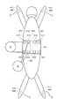
- the body fat measurement device 1 includes, as a plurality of electrodes, abdominal electrode pairs AP1 to AP4 attached to the back of the abdomen of the subject, upper limb electrodes H11 and H21 attached to the upper limb of the subject, and a lower limb attached to the lower limb of the subject. Electrodes F11 and F21 are provided.
- the control unit 10 is configured by a CPU (Central Processor Unit), for example, and performs overall control of the body fat measurement device 1. Specifically, the control unit 10 sends commands to the various functional blocks described above and performs various arithmetic processes based on the obtained information. Among these, various arithmetic processes are performed by the arithmetic processing unit 11 provided in the control unit 10.
- a CPU Central Processor Unit
- the abdominal electrode pairs AP1 to AP4 are attached to the surface of the back of the subject's abdomen in the body axis direction.
- the upper limb electrodes H11 and H21 are preferably mounted on the surface of the wrist of the right hand and the surface of the wrist of the left hand, respectively.
- the lower limb electrodes F11 and F21 are preferably mounted on the ankle surface of the right foot and the ankle surface of the left foot, respectively.
- the abdominal electrode pairs AP1 to AP4, the upper limb electrodes H11 and H21, and the lower limb electrodes F11 and F21 are electrically connected to the terminal switching unit 22, respectively.
- the terminal switching unit 22 is constituted by a plurality of relay circuits, for example.
- the terminal switching unit 22 electrically connects the specific electrode pair selected from the plurality of electrodes described above and the constant current generation unit 21 based on the command received from the control unit 10, and A specific electrode pair selected from the electrodes and the potential difference detection unit 23 are electrically connected.
- the electrode pair electrically connected to the constant current generating unit 21 by the terminal switching unit 22 functions as a constant current applying electrode pair, and is electrically connected to the potential difference detecting unit 23 by the terminal switching unit 22.
- the electrode pair thus formed functions as a potential difference detection electrode pair.
- Various electrical connections by the terminal switching unit 22 are switched during the measurement operation.
- the constant current generation unit 21 generates a constant current based on a command received from the control unit 10 and supplies the generated constant current to the terminal switching unit 22.
- the constant current generator 21 supplies, for example, a high-frequency current (for example, 50 kHz, 500 ⁇ A) that is preferably used for measuring body composition information.
- a constant current is applied to the subject via the electrode pair electrically connected to the constant current generating unit 21 by the terminal switching unit 22, that is, the constant current applying electrode pair.
- the potential difference detection unit 23 detects a potential difference between the electrodes of the electrode pair electrically connected to the potential difference detection unit 23 by the terminal switching unit 22, that is, the potential difference detection electrode pair, and outputs the detected potential difference to the control unit 10. Thereby, the potential difference between the electrodes of the potential difference detection electrode pair in a state where the constant current is applied to the subject is detected.
- the physique information measuring unit 24 and the subject information input unit 25 are parts for obtaining subject information used for the arithmetic processing performed in the arithmetic processing unit 11 of the control unit 10.
- the subject information means information about the subject, and includes at least one of information such as age, sex, and physique information.
- the physique information is information on the size of a specific part of the body of the subject, for example, information including at least one of waist length (abdominal circumference), abdominal width and abdominal thickness, and height And information such as weight.
- the physique information measuring unit 24 is a part that automatically measures the physique information of the subject, and outputs the measured physique information to the control unit 10.
- the subject information input unit 25 is a part for inputting subject information, and outputs the input subject information to the control unit 10.
- the functional block diagram shown in FIG. 1 illustrates the case where both the physique information measurement unit 24 and the subject information input unit 25 are provided in the body fat measurement device 1, but these physique information measurement unit 24
- the subject information input unit 25 is not necessarily an essential configuration. Whether or not to provide the physique information measuring unit 24 and / or the subject information input unit 25 is appropriately selected based on the type of subject information used in the arithmetic processing performed in the arithmetic processing unit 11 of the control unit 10. .
- the physique information may be configured to be automatically measured by the physique information measurement unit 24, or the subject himself / herself may input the physique information in the subject information input unit 25.
- the arithmetic processing unit 11 includes an impedance calculation unit 12 and various fat amount calculation units 13.
- the impedance calculation unit 12 calculates various impedances based on the current value of the constant current generated by the constant current generation unit 21 and the potential difference information detected by the potential difference detection unit 23 and received by the control unit 10.
- the various fat mass calculation unit 13 calculates various fat masses based on the impedance information obtained in the impedance calculation unit 12 and the subject information received from the physique information measurement unit 24 and / or the subject information input unit 25.
- the various fat mass calculation units 13 include, for example, a body fat mass calculation unit 14 that calculates the body fat mass of the whole body of the subject, a body fat mass calculation unit 15 that calculates a fat mass for each specific part of the subject, It includes at least one of a visceral fat amount calculation unit 16 that calculates the visceral fat amount and a subcutaneous fat amount calculation unit 17 that calculates the subcutaneous fat amount in the abdomen of the subject.
- the body fat mass calculation unit 14 and the subcutaneous fat mass calculation unit 17 may be included in the visceral fat mass calculation unit 16.
- the display unit 26 displays information on various fat amounts calculated by the arithmetic processing unit 11.
- an LCD Liquid Crystal Display
- the fat mass displayed on the display unit 26 includes, for example, the body fat mass of the subject, the fat mass for each specific part of the subject, the visceral fat mass, the subcutaneous fat mass in the abdomen, and the like.
- the fat amount means an index indicating the amount of fat, such as fat weight, fat area, fat volume and fat level, and particularly for visceral fat amount, not only visceral fat weight but also visceral fat area, It refers to at least one of visceral fat volume and visceral fat level.
- the operation unit 27 is a part for the subject to input a command to the body fat measurement device 1, and is configured by, for example, a key that can be pressed by the subject.
- the power supply unit 28 is a part for supplying power to the control unit 10 and the like, and includes an internal power source such as a battery and an external power source such as a commercial power source.
- the memory unit 29 is a part for storing various data and programs related to the body fat measurement device 1. For example, the subject information described above, the calculated visceral fat mass, and a body fat measurement process described later are executed. A body fat measurement program and the like are stored.
- the body fat measurement device 1 according to the present embodiment can measure various fat masses in the various fat mass calculation units 13, but in the following, the visceral fat area as an index indicating the visceral fat mass An example of the arithmetic processing that is performed in the calculation of.
- impedance calculation unit 12 calculates two types of impedance based on the current value generated in constant current generation unit 21 and the potential difference detected in potential difference detection unit 23.
- One of the two types of impedance is impedance that reflects the lean mass in the abdomen of the subject (hereinafter, impedance is also referred to as Zt).
- the other impedance is an impedance reflecting the amount of subcutaneous fat in the abdomen of the subject (hereinafter, impedance is also referred to as Zs).
- the visceral fat mass calculation unit 16 calculates the visceral fat mass of the subject, for example, the visceral fat area (unit: cm 2) based on the calculated two types of impedances Zt and Zs and the physique information (waist length) of the subject. To do. Specifically, for example, the visceral fat area Sv is calculated by the following equation (1) representing the relationship between the two types of impedances Zt and Zs and the waist length of the subject and the visceral fat area.
- the subcutaneous fat mass calculation unit 17 calculates the subcutaneous fat mass of the subject, for example, the subcutaneous fat area (unit: cm 2) based on the calculated impedance Zs and the physique information (waist length) of the subject.
- the subcutaneous fat area Ss is calculated by the following equation (2) representing the relationship between the impedance Zs and the waist length of the subject and the subcutaneous fat area.
- the body fat mass calculation unit 14 calculates the fat free mass FFM (unit: kg) based on the calculated impedance Zt and one piece of information (for example, height) included in the physique information of the subject.
- the fat free mass FFM is calculated by the following equation (3) representing the relationship between the impedance Zt and the height of the subject and the fat free mass.
- FFM i ⁇ 2 ⁇ H / Zt + j (3) (Where i, j are coefficients, H is height).
- the coefficients in each of the above formulas (1), (2), and (3) are determined by, for example, a regression formula based on the measurement result by MRI. Moreover, the coefficient in each of Formula (1), (2), (3) may be defined for every age and / or sex.
- the body fat mass calculating unit 14 calculates the body fat mass of the subject, for example, the body fat percentage (% ) Is calculated. Specifically, for example, the body fat percentage is calculated by the following equation (4) based on the lean mass FFM and the weight of the subject.
- Body fat percentage (Wt ⁇ FFM) / Wt ⁇ 100 (4) (Wt: body weight).
- FIG. 2 is a diagram illustrating an arrangement example of electrodes in the body fat measurement device according to the embodiment of the present invention.
- FIG. 2 shows a state where the upper limb electrode, the lower limb electrode, and the abdominal electrode are arranged.
- FIG. 2 is an example of electrode arrangement viewed from the back side of the subject.
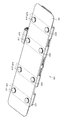
- the body fat measuring device 1 includes an electrode belt 100 and a limb clip 400.
- the electrode belt 100 is formed by integrally forming the abdominal electrode pairs AP1, AP2, AP3, AP4 and the belt material 101.
- the abdominal electrode pair AP1 includes abdominal electrodes A11 and A21.
- the abdominal electrode pair AP2 includes abdominal electrodes A12 and A22.
- the abdominal electrode pair AP3 includes abdominal electrodes A13 and A23.
- the abdominal electrode pair AP4 includes abdominal electrodes A14 and A24.
- abdominal electrode pairs AP1, AP2, AP3, AP4 two pairs of electrodes are arranged in the body axis direction on the back of the abdomen of the subject, and each electrode pair is arranged in a direction substantially perpendicular to the body axis and spaced from each other. Is done.
- the abdominal electrode pair AP2 is arranged at a predetermined distance from an axis passing through the abdominal electrodes A11 and A21 of the abdominal electrode pair AP1.
- the distance between the electrodes of the abdominal electrode pairs AP1, AP2, AP3, AP4 is substantially equal.
- the distance between the abdominal electrodes A11 and A21 of the abdominal electrode pair AP1 and the distance between the abdominal electrodes A12 and A22 of the abdominal electrode pair AP2 are substantially equal.
- Each of the electrodes of the abdominal electrode pairs AP1, AP2, AP3, AP4 is arranged in alignment with the electrodes of the corresponding other electrode pairs in a direction substantially perpendicular to the body axis. That is, the abdominal electrodes A11, A12, A13, A14 are arranged in a line in a direction substantially perpendicular to the body axis.
- the abdominal electrodes A21, A22, A23, A24 are arranged in a line in a direction substantially perpendicular to the body axis.
- the abdominal electrode pairs AP1, AP2, AP3, AP4 may be arranged in a line in the body axis direction.
- the abdominal electrode pairs AP2, AP3, AP4 may be arranged on an axis passing through the abdominal electrodes A11, A21 of the abdominal electrode pair AP1.
- abdominal electrode pairs AP1, AP2 are arranged in a line in the body axis direction, and abdominal electrode pair AP1 is arranged at a position sandwiching abdominal electrode pair AP2.
- the abdominal electrode pair AP3, AP4 may be arranged in a line in the body axis direction, and the abdominal electrode pair AP3 may be arranged at a position sandwiching the abdominal electrode pair AP4.
- the limb clip 400 holds the upper limb electrodes H11 and H21 and the lower limb electrodes F11 and F21, and is attached to the surface of the wrist of the right hand, the surface of the wrist of the left hand, the surface of the ankle of the right foot, and the surface of the ankle of the left foot, respectively. Has been.
- the constant current generator 21 causes a current to flow between electrodes of an electrode pair (hereinafter also referred to as a current electrode pair) electrically connected to the constant current generator 21 by the terminal switching unit 22.
- the potential difference detection unit 23 detects a potential difference between electrodes of an electrode pair (hereinafter also referred to as a voltage electrode pair) electrically connected to the potential difference detection unit 23 by the terminal switching unit 22.
- the visceral fat mass calculation unit 16 calculates the visceral fat mass of the subject based on the potential difference between the electrodes of the voltage electrode pair detected by the potential difference detection unit 23.
- FIG. 3 is a flowchart that defines an operation procedure when the body fat measurement device according to the present embodiment measures the visceral fat mass.
- the processing shown in the flowchart of FIG. 3 is stored in advance in the memory unit 29 as a program, and the function of the visceral fat measurement processing is realized by the control unit 10 reading and executing this program.
- control unit 10 receives input of subject information including physique information (waist length) (step S2).
- the subject information received here is temporarily stored in the memory unit 29, for example.
- control unit 10 determines whether or not there is an instruction to start measurement (step S4). Control unit 10 waits for an instruction to start measurement (NO in step S4). When control unit 10 detects an instruction to start measurement (YES in step S4), it performs electrode setting (step S8).
- control unit 10 first performs an impedance Zt calculation process. That is, for example, the control unit 10 selects one pair of upper limb electrode H11, lower limb electrode F11 and one pair of upper limb electrode H21, lower limb electrode F21 as current electrode pairs, and selects an abdominal electrode pair AP1 as a voltage electrode pair.
- the terminal switching unit 22 electrically connects the pair of upper limb electrodes H11 and the lower limb electrodes F11 and the pair of upper limb electrodes H21 and the lower limb electrodes F21 to the constant current generation unit 21 based on the control of the control unit 10, and
- the abdominal electrode pair AP1 is electrically connected to the potential difference detection unit 23 (step S8).
- the terminal switching unit 22 disconnects the electrical connection between the non-selected electrode and the constant current generation unit 21 and the potential difference detection unit 23 based on the control of the control unit 10.
- the constant current generation unit 21 causes a current to flow from the upper limb to the lower limb based on the control of the control unit 10.
- the constant current generation unit 21 causes a current to flow from the upper limb electrode H11 and the upper limb electrode H21 to the lower limb electrode F11 and the lower limb electrode F21 (step S10).
- the terminal switching unit 22 is preferably configured to short-circuit the upper limb electrode H11 and the upper limb electrode H21 and to short-circuit the lower limb electrode F11 and the lower limb electrode F21.
- the constant current generation unit 21 and the terminal switching unit 22 may have a configuration in which a current flows from any one of the upper limb electrodes H11 and H21 to any one of the lower limb electrodes F11 and F21.
- the potential difference detection unit 23 detects a potential difference between the abdominal electrodes A11 and A21 of the abdominal electrode pair AP1 based on the control of the control unit 10 (step S12).
- the control unit 10 selects the abdominal electrode pairs AP2, AP3, AP4 as voltage electrode pairs in order. That is, the terminal switching unit 22 electrically connects the abdominal electrode pairs AP2, AP3, AP4 to the potential difference detection unit 23 in order based on the control of the control unit 10 (step S8). Then, the potential difference detection unit 23 sequentially detects the potential difference between the electrodes of the abdominal electrode pairs AP2, AP3, AP4 based on the control of the control unit 10 (step S12).
- the impedance calculation unit 12 completes the detection of the potential difference for all combinations of electrode pairs.
- the detection of the potential difference between the electrodes of the abdominal electrode pairs AP1, AP2, AP3, AP4 is completed (step Based on the current value supplied by the constant current generator 21 and the potential differences detected by the potential difference detector 23, impedances Zt1 to Zt4 are calculated (step S14).
- the values of the impedances Zt1 to Zt4 calculated by the impedance calculation unit 12 are temporarily stored in the memory unit 29, for example.
- the control unit 10 performs an impedance Zs calculation process. That is, the control unit 10 selects the abdominal electrode pair AP1 as the current electrode pair, and selects the abdominal electrode pair AP2 as the voltage electrode pair.
- the terminal switching unit 22 electrically connects the abdominal electrode pair AP1 to the constant current generating unit 21 and electrically connects the abdominal electrode pair AP2 to the potential difference detecting unit 23 based on the control of the control unit 10 (step). S16).
- the terminal switching unit 22 selectively electrically connects each abdominal electrode pair to the potential difference detection unit 23 based on the control of the control unit 10, and the unselected abdominal electrode pair, upper limb electrode, and lower limb electrode And the constant current generator 21 and the potential difference detector 23 are disconnected from each other.
- the constant current generation unit 21 causes a current to flow between the abdominal electrodes A11 and A21 of the abdominal electrode pair AP1 based on the control of the control unit 10 (step S18).
- the potential difference detector 23 detects a potential difference between the abdominal electrodes A12 and A22 of the abdominal electrode pair AP2 based on the control of the control unit 10 (step S20).
- the control unit 10 selects the abdominal electrode pairs AP3 and AP4 as voltage electrode pairs in order. That is, the terminal switching unit 22 electrically connects the abdominal electrode pairs AP3 and AP4 to the potential difference detection unit 23 in order based on the control of the control unit 10 (step S16).
- the potential difference detection unit 23 sequentially detects the potential difference between the electrodes of the abdominal electrode pair AP3 and AP4 based on the control of the control unit 10 (step S20).
- the control unit 10 selects the abdominal electrode pair AP2 as the current electrode pair, and selects the abdominal electrode pair AP1 as the voltage electrode pair. That is, the terminal switching unit 22 electrically connects the abdominal electrode pair AP2 to the constant current generation unit 21 and electrically connects the abdominal electrode pair AP1 to the potential difference detection unit 23 based on the control of the control unit 10. (Step S16).
- the constant current generation unit 21 causes a current to flow between the abdominal electrodes A12 and A22 of the abdominal electrode pair AP2 based on the control of the control unit 10 (step S18).
- the potential difference detection unit 23 detects a potential difference between the abdominal electrodes A11 and A21 of the abdominal electrode pair AP1 based on the control of the control unit 10 (step S20).
- the control unit 10 selects the abdominal electrode pairs AP3 and AP4 as voltage electrode pairs in order. That is, the terminal switching unit 22 electrically connects the abdominal electrode pairs AP3 and AP4 to the potential difference detection unit 23 in order based on the control of the control unit 10 (step S16).
- the potential difference detection unit 23 sequentially detects the potential difference between the electrodes of the abdominal electrode pair AP3 and AP4 based on the control of the control unit 10 (step S20).
- control unit 10 sequentially selects the abdominal electrode pairs AP3 and AP4 as current electrode pairs, and each of the abdominal electrode pairs AP3 and AP4 is the abdominal part of the abdominal electrode pairs AP1 to AP4 other than the current electrode pair.
- the electrode pairs are sequentially selected as voltage electrode pairs, and potential differences between the electrodes of the voltage electrode pairs are detected (steps S16 to S20).
- the impedance calculation unit 12 determines that the current value passed by the constant current generation unit 21 and the potential difference detection unit 23 Based on the detected potential differences, impedances Zs1 to Zs12 are calculated (step S22).
- the values of the impedances Zs1 to Zs12 calculated by the impedance calculation unit 12 are temporarily stored in the memory unit 29, for example.
- the visceral fat mass calculation unit 16 calculates the visceral fat area Sv based on the physique information (waist length) received by the control unit 10 in step S2, the impedances Zt1 to Zt4, and the impedances Zs1 to Zs12 ( Step S24).
- the visceral fat area Sv is calculated by the above formula (1).
- the average value of the four impedances Zt1 to Zt4 is the impedance in the equation (1).
- the average value of the twelve impedances Zs1 to Zs12 is substituted into the impedance Zs in equation (1).
- the subcutaneous fat mass calculation unit 17 calculates the subcutaneous fat area Ss based on the physique information (waist length) received by the control unit 10 in step S2 and the impedances Zs1 to Zs12 (step S26).
- the subcutaneous fat area Ss is calculated by the above equation (2).
- the average value of the twelve impedances Zs1 to Zs12 is expressed by the equation (2). Substituted for impedance Zs.
- the body fat mass calculation unit 14 calculates the lean body mass FFM based on the subject information (for example, height) input in step S2 and the impedances Zt1 to Zt4 (step S28).
- the lean mass FFM is calculated by the above equation (3).
- the average value of the four impedances Zt1 to Zt4 is expressed by the equation (3). Substituted for impedance Zt.
- the body fat mass calculation unit 14 calculates the body fat percentage based on the subject information (body weight) input in step S2 and the lean body mass FFM calculated in step S28 (step S30).
- the body fat percentage is calculated by the above equation (4).
- the display part 26 displays each measurement result based on control of the control part 10 (step S32).
- the body fat measurement device 1 ends the body fat measurement process.
- typical values of the impedances Zt1 to Zt4 are each about 5 ⁇ .
- typical values of the impedances Zs1 to Zs12 are each about 80 ⁇ .
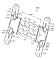
- FIGS. 4 and 5 are perspective views showing the structure of the electrode belt 100 used in the body fat measuring device
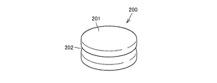
- FIG. 5 is a perspective view showing the structure of the abdominal electrode 200 provided in the electrode belt 100 used in the body fat measuring device.
- the electrode belt 100 is formed by integrally forming the abdominal electrode pairs AP1, AP2, AP3, AP4 and the belt material 101.
- An elastomeric material is used for the belt material 101, and a bellows structure is partially adopted so as to be easily deformed along the abdomen of the subject.
- the abdominal electrode pair AP1 includes abdominal electrodes A11 and A21, and the abdominal electrodes A11 and A21 are arranged with a predetermined gap in the body axis direction.
- the abdominal electrode pair AP2 also includes abdominal electrodes A12 and A22, and the abdominal electrodes A12 and A22 are arranged with a predetermined gap in the body axis direction.
- the abdominal electrode pair AP3 also includes abdominal electrodes A13 and A23, and the abdominal electrodes A13 and A23 are arranged with a predetermined gap in the body axis direction.
- the abdominal electrode pair AP4 also includes abdominal electrodes A14 and A24, and the abdominal electrodes A14 and A24 are arranged with a predetermined gap in the body axis direction.
- FIG. 5 shows the structure of the abdominal electrode 200 used for the abdominal electrodes A11, A21, A12, A22, A13, A23, A14, and A24.
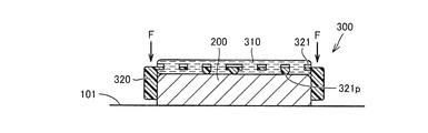
- the abdominal electrode 200 has a cylindrical shape, a diameter of about 23 mm, and a protruding height from the belt material 101 of about 6 mm.
- the abdominal part electrode 200 has a metal cylindrical electrode part 201, and an annular groove concave part 202 is provided in a waist part of the cylindrical electrode part 201.
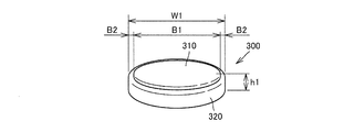
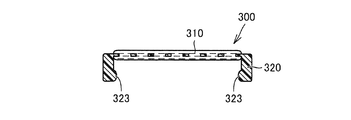
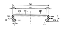
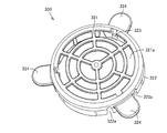
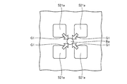
- FIGS. 6 and 7 are perspective views showing the structure of the abdominal electrode pad 300
- FIG. 7 is a plan view showing the structure of the abdominal electrode pad 300.
- the gel used in the following description is a lyophilic solute colloidal solution, which means a gel of a substance (jelly) having elasticity and low fluidity.
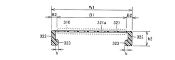
- the abdominal electrode pad 300 is provided with a circular conductive gel 310 and the conductive gel 310 so as to be electrically contactable with the abdominal electrode 200 and detachably attached to the abdominal electrode 200. And a cylindrical base member 320 having one end opened.
- a polypropylene resin material, an ABS resin, or the like is used for the base member 320.
- acrylic polymer gel, urethane gel, or the like is used as the conductive gel 310.
- the abdominal electrode pad 300 has an outer diameter (W1) of about ⁇ 26 mm and a height (h1) including the conductive gel 310 of about 7 mm. Further, in the surface portion of the abdominal electrode pad 300, the conductive gel 310 is held by the base member 320 so that the edge (region indicated by B2) of the base member 320 is exposed.
- the region where the conductive gel 310 is provided (the region indicated by B1) has a diameter of about 22 mm, and the exposed edge (the region indicated by B2) has a length of about 2 mm.
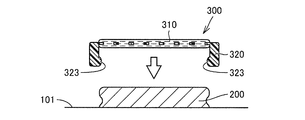
- FIGS. 8 is a cross-sectional view taken along line VIII-VIII in FIG. 7, and FIGS. 9 and 10 are first and second schematic views showing attachment of the abdominal electrode pad 300 to the abdominal electrode.
- a convex region 323 that protrudes inward in the radial direction is provided on the open end side of the cylindrical base member 320.
- region 323 may be provided in the continuous annular shape, and may be provided in several places discontinuously.
- the convex region 323 of the base member 320 is once elastically deformed so as to expand outward. Thereafter, the convex region 323 engages with the groove concave portion 202 of the abdominal electrode 200. Thereby, the abdominal electrode pad 300 is fixed to the abdominal electrode 200. At this time, the lower surface side of the conductive gel 310 provided on the abdominal electrode pad 300 contacts the upper surface portion of the abdominal electrode 200 so as to be electrically conductive.
- the base member 320 is picked and lifted with a finger.
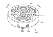
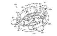
- FIGS. 11 is a first perspective view showing the structure of the base member 320 from the surface side
- FIG. 12 is a cross-sectional view taken along line XII-XII in FIG. 11
- FIG. 13 is a second view showing the structure of the base member 320 from the surface side
- FIG. 14 is a perspective view showing the structure of the base member 320 from the back side.
- the base member 320 has a cylindrical body 322 whose one end is open, and a polypropylene resin material, ABS resin, or the like is used.
- a cylindrical holding surface 321 provided with a plurality of openings 321a is provided on the other end side of the cylindrical body 322 on which the conductive gel 310 is held.
- the opening 321a formed in the holding surface 321 has a plurality of arc-shaped openings provided concentrically.
- the width of the opening 321a in the radial direction is about 2 mm, and the width of the holding surface 321 positioned between the openings 321a is about 1 mm.
- the conductive gel 310 is applied to the front surface side and the back surface side of the holding surface 321 using the opening 321a formed in this manner, and the conductive gel 310 is integrated with the base member 320 on the holding surface 321. Is held in.
- the total area of the openings 321a in the region where the conductive gel 310 is provided is 50 of the total area of the region where the conductive gel 310 is provided (the region indicated by B1 in FIG. 12). % Or better. Accordingly, when the conductive gel 310 is applied to the holding surface 321 of the base member 320, it becomes easy for the bubbles to escape from the opening, and the entrainment of the bubbles into the conductive gel 310 can be suppressed. Become. As a result, it is possible to prevent the thinning due to the time-dependent change of the conductive gel 310 at the bubble mixed portion, and to stabilize the measurement accuracy in the visceral fat measurement device.
- the protruding length (b) of the convex region 323 is about 0.5 mm. Further, the diameter (W1) of the base member 320 is about ⁇ 26 mm as described above, and the height (h2) of the base member is about 6 mm.
- a total of six slits 322a are provided on the outer peripheral surface of the cylindrical body 322 in the region where the convex region 323 is provided, and three finger hook portions 324 projecting outward in the radial direction to the region sandwiched between the slits 322a.
- region 323 mentioned above is provided in the internal peripheral surface of the cylindrical body 322 in which the finger hook part 324 is provided.
- the convex region 323 moves outward by elastically deforming the region sandwiched between the slits 322a by the finger hook portion 324, and the abdominal portion can be easily moved. It becomes possible to remove the electrode pad 300 from the abdominal electrode 200.
- region 323 and the finger hook part 324 is not limited to three, It is possible to provide one place, two places, or four places or more.
- a plurality of protrusions 321p are provided on the back side of the holding surface 321. As shown in FIG. 15, when the protrusion 321p is not provided, after the abdominal electrode pad 300 is attached to the abdominal electrode 200, the abdominal electrode pad 300 is pressed against the abdominal electrode 200 side (in FIG. 15). In the direction of arrow F), the conductive gel 310 is pushed out from the holding surface 321 and the conductive gel 310 collapses.
- the abdominal electrode pad 300 is pressed against the abdominal electrode 200 after the abdominal electrode pad 300 is attached to the abdominal electrode 200. Even when attached (in the direction of arrow F in FIG. 16), the protrusion 321p contacts the surface of the abdominal electrode 200 and suppresses the movement of the holding surface 321 to the abdominal electrode 200 side. As a result, it is possible to prevent the conductive gel 310 from being pushed out from the holding surface 321 and to prevent the conductive gel 310 from collapsing.
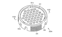
- FIG. 17 is a perspective view showing the structure of another base member
- FIG. 18 is a cross-sectional view taken along line XVIII-XVIII in FIG.
- the base member 320A also has a cylindrical body 322 that is open at one end, and is made of polypropylene resin material, ABS resin, or the like.
- a cylindrical holding surface 321 provided with a plurality of openings 321a is provided on the other end side of the cylindrical body 322 on which the conductive gel 310 is held.
- the opening 321a formed in the holding surface 321 has an opening form in which a plurality of circular openings are provided.
- the diameter of one opening 321a is about 2 mm, and the shortest distance between the openings 321a is about 1 mm.
- the conductive gel 310 is applied to the front surface side and the back surface side of the holding surface 321 by using the opening 321a formed in this way, and the conductive gel 310 is integrated with the base member 320A on the holding surface 321. Is held in.
- a convex region 323 that protrudes inward in the radial direction is provided.
- the protruding length (b) of the convex region 323 is about 0.5 mm.
- the diameter (W1) of the base member 320 is about ⁇ 26 mm as described above, and the height (h2) of the base member is about 6 mm.
- a plurality of slits 322a are provided on the outer peripheral surface of the cylindrical body 322, and a finger hook portion 324 having a plurality of convex portions extending in the circumferential direction is provided in a region sandwiched between the slits 322a.
- a finger hook portion 324 having a plurality of convex portions extending in the circumferential direction is provided in a region sandwiched between the slits 322a.
- the total area of the openings 321a in the region where the conductive gel 310 is provided is the region where the conductive gel 310 is provided (the region indicated by B1 in FIG. 18). 50) or more of the total area. Accordingly, when the conductive gel 310 is applied to the holding surface 321 of the base member 320A, it is easy for the bubbles to escape from the opening, and the entrainment of the bubbles in the conductive gel 310 can be suppressed. Become. As a result, it is possible to prevent the thinning due to the time-dependent change of the conductive gel 310 at the bubble mixed portion, and to stabilize the measurement accuracy in the visceral fat measurement device.
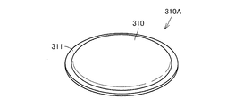
- FIGS. 19 is a perspective view showing the structure of the conductive gel sheet 310A used for the abdominal electrode pad 300B
- FIG. 20 is a perspective view showing the structure of the base member 320B
- FIG. 21 is a cross section showing the structure of the abdominal electrode pad 300B.
- the abdominal electrode pad 300B includes a conductive gel sheet 310A and a base member 320B. As shown in FIG. 19, in the conductive gel sheet 310A, the conductive gel 310 is applied in a circular shape on both surfaces of a sheet-like member 311 using a fiber member such as a circular nonwoven fabric. The peripheral edge of the sheet-like member 311 is exposed from the conductive gel 310.
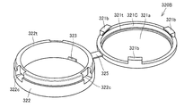
- the base member 320B includes a cylindrical body 322 whose both ends are open and an annular cap 321C having an opening 321a.
- the cylindrical body 322 and the cap 321C are connected by an elastically deformable connecting piece 325. Yes.
- the cylindrical body 322, the cap 321C, and the connecting piece 325 are all integrally formed of a polypropylene resin material, ABS resin, or the like.
- the cap 321C is provided with three engagement pieces 321b protruding in the axial direction. Further, the cylindrical body 322 is provided with an engaging recess 322c that is detachably attached to the engaging piece 321b at a position corresponding to the engaging piece 321b. A convex region 323 that protrudes inward in the radial direction is provided on the inner peripheral surface of the cylindrical body 322 opposite to the side where the cap 321C is provided.
- the conductive gel sheet 310A is sandwiched between the upper end portion 322t of the cylindrical body 322 and the flange portion 321t provided on the cap 321C so that the exposed peripheral portion of the exposed sheet-like member 311 is sandwiched between the base member 320B. It is held (see FIG. 21).
- the external dimensions of the abdominal electrode pad 300B are the same as those of the abdominal electrode pad 300 described above, the protruding length (b) of the convex region 323 is about 0.5 mm, and the diameter (W1) of the base member 320B is about ⁇ 26 mm.
- the height (h2) of the base member is 6 mm, and the height (h1) of the abdominal electrode pad 300B is 7 mm.
- the conductive gel sheet 310A As described above, by using the conductive gel sheet 310A, it is possible to discard the conductive gel sheet 310A after use and reuse the base member 320B.
- a fiber having a large mesh is used for the sheet-like member 311 of the conductive gel sheet 310A, and the total area of the openings of the eyes is at least a region where the conductive gel 310 is provided on the sheet-like member 311 (shown by B1 in FIG. 21).
- the total area of the region is preferably 50% or more. Accordingly, when the conductive gel 310 is applied to the sheet-like member 311, the bubbles can easily escape from the mesh, and the entrainment of the bubbles into the conductive gel 310 can be suppressed. As a result, it is possible to prevent the thinning due to the time-dependent change of the conductive gel 310 at the bubble mixed portion, and to stabilize the measurement accuracy in the visceral fat measurement device.
- the abdominal electrode pads 300 and 300B in the present embodiment since the conductive gel 310 is held in advance by the base members 320, 320A, and 320B, the abdominal electrode pads 300 and 300B are attached to the abdominal electrode. It is possible to easily apply the conductive gel 310 to the abdominal electrode 200 only by being attached to 200.
- the wiping work of the conductive gel 310 attached to the subject is also facilitated.
- wiping work of the conductive gel 310 attached to the abdominal electrode 200 is also facilitated.
- the application position and amount of the conductive gel 310 attached to the subject are constant, the stability of contact resistance reduction and the constant distance between the electrodes can be ensured.
- the abdominal electrode pad 300 for each electrode of the body fat measuring device described in the present embodiment the reliability of the measurement result in the body fat measuring device can be improved.
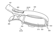
- FIG. 22 is a view showing the structure of the limb clip 400.
- the limb clip 400 has a first sandwiching clip 401 and a second sandwiching clip 402.
- the 1st clamping clip 401 and the 2nd clamping clip 402 have the loose S character shape used as symmetry.
- the first clamping clip 401 and the second clamping clip 402 are connected by an elastic clip 403 so as to be openable and closable in the direction of arrow S in the figure.
- the curved portion of the second sandwiching clip 402 facing the first sandwiching clip 401 is attached with a thin plate-like upper and lower limb electrode 404 made of stainless steel that functions as the upper limb electrodes H11 and H21 or the lower limb electrodes F11 and F21. Yes.
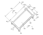
- FIGS. 23 is a perspective view showing the structure of the upper / lower limb electrode pad 500
- FIG. 24 is a sectional view taken along the line XXIV-XXIV in FIG. 23
- FIG. 25 is a sectional view taken along the line XXV-XXV in FIG. is there.
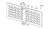
- this upper limb / lower limb electrode pad 500 holds a rectangular conductive gel 510 and this conductive gel 510 so as to be in electrical contact with the upper limb / lower limb electrode 404.
- a substantially rectangular base member 520 that is detachably attached to the upper limb / lower limb electrode 404 is provided.
- a polypropylene resin material, an ABS resin, or the like is used for the base member 520.
- acrylic polymer gel, urethane gel, or the like is used as the conductive gel 510.
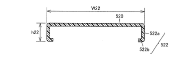
- the upper limb / lower limb electrode pad 500 has a maximum length (W21) of about 77 mm, a maximum width (W22) of about 38 mm, and a height (h21) including the conductive gel 510 of about 9 mm.
- W21 maximum length
- W22 maximum width
- h21 height
- the conductive gel 510 is held by the base member 520 so that the edge portions (regions indicated by B12 and B22) of the base member 520 are exposed.
- the region where the conductive gel 510 is provided (the region indicated by B11, B21) is B73 of about 73 mm, B21 is about 30 mm, and the exposed edge (the region indicated by B22, B12) is both B22 and B12. About 2 mm.
- Engagement regions 522 are provided at the four corners of the base member 520.
- the engagement region 522 has an arm portion 522a depending from the base member 520 and an engagement piece 522b extending inward from the arm portion 522a in parallel to the base member 520.
- FIG. 26 is a perspective view showing a state where the upper limb / lower limb electrode pad is attached to the upper limb / lower limb electrode
- FIG. 27 is a sectional view taken along line XXVII-XXVII in FIG.
- the upper limb / lower limb electrode pad 500 is attached to the upper limb / lower limb electrode 404.
- the lower surface side of the conductive gel 510 provided on the upper limb / lower limb electrode pad 500 comes into contact with the upper surface portion of the upper limb / lower limb electrode 404 so as to be electrically conductive.
- the base member 520 is picked and pulled away with a finger.
- FIGS. 28 is a perspective view showing the structure of the base member 520
- FIG. 29 is a perspective view showing another structure of the base member 520.
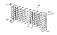
- the base member 520 has a substantially rectangular shape as a whole, and a polypropylene resin material, an ABS resin, or the like is used.
- the holding surface 521 on which the conductive gel 510 is held is provided with a plurality of rectangular openings 521a in a matrix shape, and has a net shape.
- the opening 521a formed in the holding surface 521 is a rectangular opening having a side of about 3 mm to 5 mm, and the interval between the openings 521a is about 1 mm to 2 mm.
- the conductive gel 510 is applied to the front surface side and the back surface side of the holding surface 521 using the opening 521a formed in this way, and the conductive gel 510 is integrated with the base member 520 on the holding surface 521. Is held in.
- engagement areas 522 having the arm portions 522a and the engagement pieces 522b are provided.
- the engagement area 522 is elastically deformed by the finger hook portion 523, and the upper limb / lower limb electrode pad 500 is easily deformed. It can be removed from the lower limb electrode 404.
- the total area of the openings 521a in the region where the conductive gel 510 is provided is the total area of the region where the conductive gel 510 is provided (the region indicated by B11 and B21 in FIG. 23). It may be 50% or more of the total area.
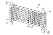
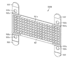
- FIG. 30 is a perspective view showing the structure of another base member.
- the base member 520 ⁇ / b> A has an opening 521 a having an opening area larger than the opening 521 a provided in the base member 520, and the engaging region 522 is a reinforcing portion 521 b provided in the central portion of the holding surface 521. Two places are provided at both ends of the. Also with this configuration, the upper limb / lower limb electrode pad 500 is held by the upper limb / lower limb electrode 404 so as to embrace the upper limb / lower limb electrode 404 and the second holding clip 402 using the engagement region 522 provided in the base member 520A. Can be attached to.
- the total area of the openings 521a in the region where the conductive gel 510 is provided is the region where the conductive gel 510 is provided (FIG. 23). (Corresponding to the regions indicated by B11 and B21) of 50% or more of the total area.
- FIG. 31 is a perspective view showing still another structure of the base member 520B
- FIG. 32 is a cross-sectional view showing a structure for attaching the base member 520B to the second holding clip 402.
- the basic structure of base member 520B is the same as base member 520 described above, and the difference is in the structure of engagement region 522.
- the engagement region 522 in the base member 520B is formed so as to be flush with the holding surface 521, and a thin portion 522y constituting a fragile region is provided in a streak shape at a connecting portion with the holding surface 521. Further, an engagement hole 522x is provided in the engagement region 522.
- An engagement protrusion 405 for engaging with an engagement hole 522x provided in the engagement region 522 is provided on the side surface of the second sandwiching clip 402 in advance.
- the engagement region 522 is bent along the thin portion 522y, and the engagement hole 522x is engaged with the engagement protrusion 405.
- the productivity of the base member 520B can be improved by forming the base member 520B into a flat shape including the engagement region 522.
- the base member 520B has less unevenness, so that a highly airtight packing method can be performed.
- the engagement hole 522x provided in the engagement region 522 the conductive gel 510 can be pressed against the upper limb / lower limb electrode 404.
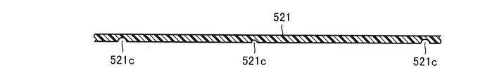
- the cross-sectional shape of the groove 521c is not limited to the U-shaped groove shown in FIG. 34 but may be a V-shaped groove.
- the groove 521c in a direction (short direction) perpendicular to the longitudinal direction of the holding surface 521, when the upper limb / lower limb electrode pad 500 is attached to the upper limb / lower limb electrode 404, the second It becomes easy to bend along the curved shape of the holding clip 402, and the contact of the conductive gel 510 to the upper limb / lower limb electrode 404 can be improved.
- the total area of the openings 521a in the region where the conductive gel 510 is provided is the region where the conductive gel 510 is provided (FIG. 23). (Corresponding to the regions indicated by B11 and B21) of 50% or more of the total area.
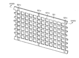
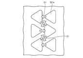
- FIG. 35 is a perspective view showing still another structure of the base member 520C.
- the basic structure of the base member 520C is the same as that of the base member 520 described above, and the difference is in the shape and arrangement of the opening 521a and the structure of the engagement region 522.
- the opening 521a has a triangular shape, and is arranged so that the hypotenuses of adjacent triangles are parallel to each other in the vertical direction in the figure, and has a net-like shape.
- the holding surface 521 is provided with a plurality of protrusions 521p similar to the protrusions 321p described in FIG.
- the holding surface 521 is provided with a pair of streak-like convex walls 521x so as to define a region where the conductive gel 510 is provided (regions indicated by B11 and B21 in FIG. 35).
- the engaging region 522 in the base member 520C is connected to the holding surface 521 with the stepped portion 522d and the thin portion 522y constituting the weak region interposed therebetween.
- An engagement hole 522x is provided in the engagement region 522.
- a region where the engagement region 522 of the holding surface 521 is connected region outside the region indicated by B11 in FIG. 35
- a thick portion 522z having a thickness larger than the thickness of the holding surface 521 is provided.
- the mounting structure of the base member 520C to the second holding clip 402 is the same as the base member 520B described in FIG.
- the total area of the openings 521a in the region where the conductive gel 510 is provided is the region where the conductive gel 510 is provided (FIG. 35). (Corresponding to the regions indicated by B11 and B21) of 50% or more of the total area.
- FIG. 36 shows a pattern of the opening 521a employed in the base members 520, 520A, and 520B.
- the flow of the conductive gel 510 introduced from the opening 521a is considered to be as indicated by an arrow G1 in the figure.
- the region surrounded by the corner of the opening 521a of the holding surface 521 the region having the same distance from the end of the opening
- bubbles are entrained in the conductive gel 510.
- relatively large bubbles Ba may remain in the conductive gel 510.
- FIG. 37 shows a pattern of the opening 521a employed in the base member 520C.
- the opening 521a has a triangular shape, and is arranged so that oblique sides of adjacent triangles are parallel to each other in the vertical direction in the figure.
- the area of the same distance from the end of the opening is reduced, and more bubble escape areas can be formed.
- entrainment of bubbles in the conductive gel 510 is improved, and the remaining of bubbles in the conductive gel 510 can be suppressed.
- the upper limb / lower limb electrode pad 500 in the present embodiment since the conductive gel 510 is held in advance by the base member 520, the upper limb / lower limb electrode pad 500 is used as the upper limb / lower limb electrode 404.
- the conductive gel 510 can be easily applied to the upper limb / lower limb electrode 404 only by wearing.
- the wiping work of the conductive gel 510 attached to the subject is also facilitated.
- the wiping operation of the conductive gel 510 attached to the upper limb / lower limb electrode 404 is facilitated.
- the application position and amount of the conductive gel 510 attached to the subject are constant, the stability of contact resistance reduction and the constant distance between the electrodes can be ensured. Thereby, it becomes possible to improve the reliability of the measurement result in the body fat measurement device by using the upper / lower limb electrode pad 500 for each electrode of the body fat measurement device described in the present embodiment.
- the electrode pad attached to the electrode used in the body fat measuring device is described.
- the electrode pad is not limited to the electrode used in the body fat measuring device. Absent.
- the electrode pad according to the present invention can be applied to electrodes used in electrocardiograms, electromyograms, low-frequency massagers, EMS (Electro Muscle Stimulation), brain waveform measuring devices, and the like.
Landscapes
- Health & Medical Sciences (AREA)
- Life Sciences & Earth Sciences (AREA)
- Biomedical Technology (AREA)
- Molecular Biology (AREA)
- Radiology & Medical Imaging (AREA)
- Biophysics (AREA)
- Pathology (AREA)
- Engineering & Computer Science (AREA)
- Nuclear Medicine, Radiotherapy & Molecular Imaging (AREA)
- Heart & Thoracic Surgery (AREA)
- Medical Informatics (AREA)
- Physics & Mathematics (AREA)
- Surgery (AREA)
- Animal Behavior & Ethology (AREA)
- General Health & Medical Sciences (AREA)
- Public Health (AREA)
- Veterinary Medicine (AREA)
- Measurement And Recording Of Electrical Phenomena And Electrical Characteristics Of The Living Body (AREA)
- Electrotherapy Devices (AREA)
Priority Applications (1)
| Application Number | Priority Date | Filing Date | Title |
|---|---|---|---|
| CN201180055443.5A CN103220969B (zh) | 2010-11-17 | 2011-10-26 | 电极用敷垫 |
Applications Claiming Priority (4)
| Application Number | Priority Date | Filing Date | Title |
|---|---|---|---|
| JP2010-256642 | 2010-11-17 | ||
| JP2010256642 | 2010-11-17 | ||
| JP2011109650A JP5751002B2 (ja) | 2010-11-17 | 2011-05-16 | 電極用パッド |
| JP2011-109650 | 2011-05-16 |
Publications (1)
| Publication Number | Publication Date |
|---|---|
| WO2012066912A1 true WO2012066912A1 (ja) | 2012-05-24 |
Family
ID=46083851
Family Applications (1)
| Application Number | Title | Priority Date | Filing Date |
|---|---|---|---|
| PCT/JP2011/074641 Ceased WO2012066912A1 (ja) | 2010-11-17 | 2011-10-26 | 電極用パッド |
Country Status (3)
| Country | Link |
|---|---|
| JP (1) | JP5751002B2 (enExample) |
| CN (1) | CN103220969B (enExample) |
| WO (1) | WO2012066912A1 (enExample) |
Cited By (2)
| Publication number | Priority date | Publication date | Assignee | Title |
|---|---|---|---|---|
| CN107921259A (zh) * | 2015-09-04 | 2018-04-17 | 欧姆龙健康医疗事业株式会社 | 低频治疗仪及其垫片、主体部、支架、支架与垫片的组合 |
| EP3308705A1 (en) * | 2016-10-12 | 2018-04-18 | LG Electronics Inc. | Body composition measuring device |
Families Citing this family (8)
| Publication number | Priority date | Publication date | Assignee | Title |
|---|---|---|---|---|
| EP3046465B1 (en) | 2013-09-16 | 2017-07-05 | Koninklijke Philips N.V. | Bio-medical electrode |
| CN103505201B (zh) * | 2013-10-24 | 2015-10-07 | 刘卫明 | 可配置干湿方式的穿戴式心电电极 |
| WO2015166752A1 (ja) | 2014-04-28 | 2015-11-05 | 株式会社村田製作所 | 生体信号検出装置 |
| JP2016202690A (ja) * | 2015-04-24 | 2016-12-08 | 株式会社 Mtg | 筋肉電気刺激装置 |
| CN106974638A (zh) * | 2016-12-22 | 2017-07-25 | 王艳景 | 便携贴式无线心电图(ecg)采集监测装置 |
| CN113546314B (zh) * | 2020-04-26 | 2025-03-25 | 未来穿戴技术有限公司 | 颈部按摩仪、用于颈部按摩仪的按摩头及其导电凝胶组件 |
| CN113546313B (zh) * | 2020-04-26 | 2025-02-25 | 未来穿戴技术有限公司 | 颈部按摩仪、用于颈部按摩仪的按摩头组件及其凝胶套 |
| CN113546312B (zh) * | 2020-04-26 | 2025-04-22 | 未来穿戴技术有限公司 | 颈部按摩仪、用于颈部按摩仪的按摩头组件及其凝胶套 |
Citations (5)
| Publication number | Priority date | Publication date | Assignee | Title |
|---|---|---|---|---|
| JPH03128040A (ja) * | 1989-10-13 | 1991-05-31 | Fukuda Denshi Co Ltd | 生体電極 |
| JPH0595922A (ja) * | 1991-10-08 | 1993-04-20 | Nippon Achison Kk | 生体用電極およびその製造方法 |
| JP2002522178A (ja) * | 1998-08-11 | 2002-07-23 | コンメド コーポレーション | ミシン目の線を有する生体臨床医学用電極 |
| JP2004195218A (ja) * | 2002-12-06 | 2004-07-15 | Hisamitsu Pharmaceut Co Inc | イオントフォレーシス装置 |
| JP2010246751A (ja) * | 2009-04-16 | 2010-11-04 | Masayoshi Fukuda | 生体電極パッド、生体電極、粘着パッド及び粘着パッドシート |
Family Cites Families (3)
| Publication number | Priority date | Publication date | Assignee | Title |
|---|---|---|---|---|
| SE9402339D0 (sv) * | 1994-07-01 | 1994-07-01 | Humanteknik Ab | Övergångselement för en biomedicinsk elektrod |
| ATE441452T1 (de) * | 2006-01-23 | 2009-09-15 | Koninkl Philips Electronics Nv | Verbesserte biomedizinische elektrode zur längeren anwendung bei patienten mit einem deckel oder schnapper, der von der haltedichtung isoliert ist |
| JP5250287B2 (ja) * | 2008-03-28 | 2013-07-31 | 積水化成品工業株式会社 | ゲル電極 |
-
2011
- 2011-05-16 JP JP2011109650A patent/JP5751002B2/ja active Active
- 2011-10-26 WO PCT/JP2011/074641 patent/WO2012066912A1/ja not_active Ceased
- 2011-10-26 CN CN201180055443.5A patent/CN103220969B/zh active Active
Patent Citations (5)
| Publication number | Priority date | Publication date | Assignee | Title |
|---|---|---|---|---|
| JPH03128040A (ja) * | 1989-10-13 | 1991-05-31 | Fukuda Denshi Co Ltd | 生体電極 |
| JPH0595922A (ja) * | 1991-10-08 | 1993-04-20 | Nippon Achison Kk | 生体用電極およびその製造方法 |
| JP2002522178A (ja) * | 1998-08-11 | 2002-07-23 | コンメド コーポレーション | ミシン目の線を有する生体臨床医学用電極 |
| JP2004195218A (ja) * | 2002-12-06 | 2004-07-15 | Hisamitsu Pharmaceut Co Inc | イオントフォレーシス装置 |
| JP2010246751A (ja) * | 2009-04-16 | 2010-11-04 | Masayoshi Fukuda | 生体電極パッド、生体電極、粘着パッド及び粘着パッドシート |
Cited By (2)
| Publication number | Priority date | Publication date | Assignee | Title |
|---|---|---|---|---|
| CN107921259A (zh) * | 2015-09-04 | 2018-04-17 | 欧姆龙健康医疗事业株式会社 | 低频治疗仪及其垫片、主体部、支架、支架与垫片的组合 |
| EP3308705A1 (en) * | 2016-10-12 | 2018-04-18 | LG Electronics Inc. | Body composition measuring device |
Also Published As
| Publication number | Publication date |
|---|---|
| JP2012120825A (ja) | 2012-06-28 |
| CN103220969B (zh) | 2015-04-01 |
| CN103220969A (zh) | 2013-07-24 |
| JP5751002B2 (ja) | 2015-07-22 |
Similar Documents
| Publication | Publication Date | Title |
|---|---|---|
| JP5751002B2 (ja) | 電極用パッド | |
| US11724106B2 (en) | Systems and apparatus for gait modulation and methods of use | |
| US5370116A (en) | Apparatus and method for measuring electrical activity of heart | |
| RU2425628C2 (ru) | Устройство измерения висцерального жира | |
| CN103025235B (zh) | 体脂肪测定装置 | |
| JP6714330B2 (ja) | 心肺蘇生術補助装置 | |
| WO2007043271A1 (ja) | 内臓脂肪量を精度良く測定することのできる体脂肪測定装置 | |
| JP5751003B2 (ja) | パッド用トレイ | |
| CN102631190B (zh) | 心血管监测装置 | |
| WO2008032291A2 (en) | Multi-electrode patches for electrophysiological impedance measurements and devices for' positioning and/or alignment of electrode- patch assemblies | |
| KR20130110304A (ko) | 심전도가 측정가능한 혈압 측정 장치 | |
| JP5050595B2 (ja) | 電極クリップ | |
| CN110801219B (zh) | 体表生物电电极支架、带形装置及心电测量装置 | |
| US11185284B2 (en) | Wearable electrocardiogram device | |
| JP7511223B2 (ja) | 電流刺激装置 | |
| CN115052526B (zh) | 带电极的绑带和生物体装接设备 | |
| JP2018175388A (ja) | 心電計用電極装置 | |
| US20240197248A1 (en) | Biometric information measurement device, control method of biometric information measurement device, and program | |
| WO2025205846A1 (ja) | 生体情報監視装置、生体情報監視システム及び貼付型生体情報監視装置 | |
| JP2007175372A (ja) | 体組成測定装置 | |
| JP2006288885A (ja) | 位置決めガイド部を備えた測定装置 |
Legal Events
| Date | Code | Title | Description |
|---|---|---|---|
| 121 | Ep: the epo has been informed by wipo that ep was designated in this application |
Ref document number: 11840725 Country of ref document: EP Kind code of ref document: A1 |
|
| DPE1 | Request for preliminary examination filed after expiration of 19th month from priority date (pct application filed from 20040101) | ||
| NENP | Non-entry into the national phase |
Ref country code: DE |
|
| 122 | Ep: pct application non-entry in european phase |
Ref document number: 11840725 Country of ref document: EP Kind code of ref document: A1 |