WO2012066912A1 - Electrode pad - Google Patents
Electrode pad Download PDFInfo
- Publication number
- WO2012066912A1 WO2012066912A1 PCT/JP2011/074641 JP2011074641W WO2012066912A1 WO 2012066912 A1 WO2012066912 A1 WO 2012066912A1 JP 2011074641 W JP2011074641 W JP 2011074641W WO 2012066912 A1 WO2012066912 A1 WO 2012066912A1
- Authority
- WO
- WIPO (PCT)
- Prior art keywords
- electrode
- base member
- conductive gel
- abdominal
- electrode pad
- Prior art date
Links
Images


Classifications
-
- A—HUMAN NECESSITIES
- A61—MEDICAL OR VETERINARY SCIENCE; HYGIENE
- A61B—DIAGNOSIS; SURGERY; IDENTIFICATION
- A61B5/00—Measuring for diagnostic purposes; Identification of persons
- A61B5/05—Detecting, measuring or recording for diagnosis by means of electric currents or magnetic fields; Measuring using microwaves or radio waves
- A61B5/053—Measuring electrical impedance or conductance of a portion of the body
- A61B5/0537—Measuring body composition by impedance, e.g. tissue hydration or fat content
-
- A—HUMAN NECESSITIES
- A61—MEDICAL OR VETERINARY SCIENCE; HYGIENE
- A61B—DIAGNOSIS; SURGERY; IDENTIFICATION
- A61B2562/00—Details of sensors; Constructional details of sensor housings or probes; Accessories for sensors
- A61B2562/14—Coupling media or elements to improve sensor contact with skin or tissue
Definitions
- the present invention relates to an electrode pad to be attached to an electrode that comes into contact with a living body.
- the electrode that is in contact with the living body is a water-containing highly fluid gel having conductivity (hereinafter simply referred to as a fluid conductive gel (commonly referred to as “gel”). Is applied to the surface of the electrode. Thereby, the contact resistance between an electrode and a biological body is reduced, and the improvement of the measurement precision of the electrical signal from a biological body is aimed at.
- a fluid conductive gel commonly referred to as “gel”.
- the “gel” usually means a lyophilic solute colloidal solution having elasticity and small fluidity (jelly-like). Therefore, in the present specification, a substance simply indicated as “conductive gel” means a substance having a normal elastic force and low fluidity (jelly-like), and “flowable conductive gel” means elasticity. It means a substance with high fluidity that you do not have.
- Patent Document 1 Japanese Patent Application Laid-Open No. 04-244171 (Patent Document 1) and Japanese Patent Application Laid-Open No. 04-303415 (Patent Document 2), there is a living body electrode in which a fluid conductive gel is provided on the surface of an electrode to be brought into contact with the living body. It is disclosed.
- the problem to be solved by the present invention is that, when a fluid conductive gel is used on the surface of the electrode, it is troublesome to apply the fluid conductive gel to the surface of each electrode. The work of wiping off the gel is troublesome.
- An object of the present invention is to solve the above-described problem. Even when a conductive gel having low fluidity is used on the surface of the electrode, the application of the conductive gel to each electrode is facilitated, the electrode surface, and the living body. It is an object to provide an electrode pad having a structure capable of facilitating the wiping operation of the conductive gel from the substrate.
- the electrode pad according to the present invention is an electrode pad to be attached to the electrode, and holds the conductive gel and the conductive gel so as to be in contact with the electrode.
- a detachable base member As described above, the “conductive gel” here is a colloidal solution of a lyophilic solute, unlike the fluid conductive gel, and has elasticity and low fluidity (jelly-like). Means a gel of matter.
- the base member includes a holding surface having an opening, and the conductive gel is held on the holding surface so as to be integrated with the base member.
- the total area of the openings in the region where the conductive gel is provided of the base member is 50% or more of the total area of the region where the conductive gel is provided.
- At least a region where the conductive gel is provided in the base member is a mesh member.
- At least a region of the base member where the conductive gel is provided is a fibrous member.
- the conductive gel is held on the base member so that the edge of the base member is exposed.
- the base member includes an engagement region that can be attached to and detached from the electrode by elastic deformation.
- the base member further includes a finger hook portion for engaging a user's finger when removing the electrode pad from the electrode.
- the base member is a polypropylene resin material.
- the conductive gel is an acrylic polymer gel or a urethane gel containing an electrolytic solution.
- the electrode is an electrode used in a visceral fat measurement device.
- the electrode pad based on the present invention even when a conductive gel having low fluidity is used on the surface of the electrode, the application work of the conductive gel to each electrode is facilitated, the conductivity from the electrode surface and the living body is improved. It is an object of the present invention to provide an electrode pad having a structure capable of facilitating the wiping operation of the conductive gel.
- FIG. 1 It is a functional block diagram of the body fat measuring device in an embodiment. It is a figure (figure seen from the back side) which shows the example of arrangement
- FIG. 8 is a cross-sectional view taken along line VIII-VIII in FIG. It is a 1st schematic diagram which shows the attachment to the abdominal part electrode of the pad for abdominal part electrodes in embodiment. It is a 2nd schematic diagram which shows the attachment to the abdominal part electrode of the pad for abdominal part electrodes in embodiment. It is the 1st perspective view seen from the surface side which shows the structure of the base member of the pad for abdominal electrodes in an embodiment.
- FIG. 12 is a cross-sectional view taken along line XII-XII in FIG. It is the 2nd perspective view seen from the surface side which shows the structure of the base member of the pad for abdominal electrodes in an embodiment.
- FIG. 18 is a cross-sectional view taken along line XVIII-XVIII in FIG. It is a perspective view which shows the structure of the electroconductive gel sheet used for the pad for other abdominal electrode in embodiment. It is a perspective view which shows the structure of the other base member of the pad for abdominal electrodes in embodiment.
- FIG. 24 is a cross-sectional view taken along line XXIV-XXIV in FIG.
- FIG. 24 is a cross-sectional view taken along line XXV-XXV in FIG.
- FIG. 24 is a perspective view which shows the attachment state to the upper limb / lower limb electrode in the upper limb / lower limb electrode pad in the embodiment.
- FIG. 27 is a cross-sectional view taken along line XXVII-XXVII in FIG. It is a perspective view which shows the structure of the base member of the upper limb / lower limb electrode pad in the embodiment. It is a perspective view which shows the other structure of the base member of the pad for upper limbs / lower limb electrodes in an embodiment. It is a perspective view which shows the other structure of the base member of the pad for upper limbs / lower limb electrodes in an embodiment. It is a perspective view which shows the other structure of the base member of the pad for upper limbs / lower limb electrodes in an embodiment.
- FIG. 34 is a sectional view taken along line XXXIV-XXXIV in FIG. 33. It is a perspective view which shows the other structure of the base member of the pad for upper limbs / lower limb electrodes in an embodiment. It is the 1st schematic diagram explaining the flow of conductive gel. It is the 2nd schematic diagram explaining the flow of conductive gel.
- the “body fat measuring device” includes “a visceral fat measuring device”.
- the “abdomen” is the portion of the trunk that excludes the chest.
- the “part away from the abdomen” means the upper limb including the upper arm, the forearm, the wrist and the fingers, the chest separated from the diaphragm by a predetermined distance (for example, approximately 10 cm) or more, and the upper body including the shoulder, the neck and the head.
- lower limbs composed of thighs, lower legs, ankles and toes.
- the “body axis” is an axis in a direction substantially perpendicular to the cross section of the subject's abdomen.
- the “abdomen front surface” includes a portion of the abdomen of the subject that is visible when the subject is observed from the front.
- the “abdominal back surface” includes a portion of the abdomen of the subject that is visible when the subject is observed from behind. For example, it includes a portion of the abdomen of the subject that is visible when the subject is observed from the spine side along an axis perpendicular to the subject's body axis while passing through the subject's navel and spine.
- FIG. 1 is a functional block diagram of the body fat measurement device according to the present embodiment. First, the configuration of the body fat measurement device will be described with reference to FIG.
- the body fat measurement device 1 includes a control unit 10, a constant current generation unit 21, a terminal switching unit 22, a potential difference detection unit 23, a physique information measurement unit 24, and a subject information input unit 25.
- the control unit 10 includes an arithmetic processing unit 11.
- the body fat measurement device 1 includes, as a plurality of electrodes, abdominal electrode pairs AP1 to AP4 attached to the back of the abdomen of the subject, upper limb electrodes H11 and H21 attached to the upper limb of the subject, and a lower limb attached to the lower limb of the subject. Electrodes F11 and F21 are provided.
- the control unit 10 is configured by a CPU (Central Processor Unit), for example, and performs overall control of the body fat measurement device 1. Specifically, the control unit 10 sends commands to the various functional blocks described above and performs various arithmetic processes based on the obtained information. Among these, various arithmetic processes are performed by the arithmetic processing unit 11 provided in the control unit 10.
- a CPU Central Processor Unit
- the abdominal electrode pairs AP1 to AP4 are attached to the surface of the back of the subject's abdomen in the body axis direction.
- the upper limb electrodes H11 and H21 are preferably mounted on the surface of the wrist of the right hand and the surface of the wrist of the left hand, respectively.
- the lower limb electrodes F11 and F21 are preferably mounted on the ankle surface of the right foot and the ankle surface of the left foot, respectively.
- the abdominal electrode pairs AP1 to AP4, the upper limb electrodes H11 and H21, and the lower limb electrodes F11 and F21 are electrically connected to the terminal switching unit 22, respectively.
- the terminal switching unit 22 is constituted by a plurality of relay circuits, for example.
- the terminal switching unit 22 electrically connects the specific electrode pair selected from the plurality of electrodes described above and the constant current generation unit 21 based on the command received from the control unit 10, and A specific electrode pair selected from the electrodes and the potential difference detection unit 23 are electrically connected.
- the electrode pair electrically connected to the constant current generating unit 21 by the terminal switching unit 22 functions as a constant current applying electrode pair, and is electrically connected to the potential difference detecting unit 23 by the terminal switching unit 22.
- the electrode pair thus formed functions as a potential difference detection electrode pair.
- Various electrical connections by the terminal switching unit 22 are switched during the measurement operation.
- the constant current generation unit 21 generates a constant current based on a command received from the control unit 10 and supplies the generated constant current to the terminal switching unit 22.
- the constant current generator 21 supplies, for example, a high-frequency current (for example, 50 kHz, 500 ⁇ A) that is preferably used for measuring body composition information.
- a constant current is applied to the subject via the electrode pair electrically connected to the constant current generating unit 21 by the terminal switching unit 22, that is, the constant current applying electrode pair.
- the potential difference detection unit 23 detects a potential difference between the electrodes of the electrode pair electrically connected to the potential difference detection unit 23 by the terminal switching unit 22, that is, the potential difference detection electrode pair, and outputs the detected potential difference to the control unit 10. Thereby, the potential difference between the electrodes of the potential difference detection electrode pair in a state where the constant current is applied to the subject is detected.
- the physique information measuring unit 24 and the subject information input unit 25 are parts for obtaining subject information used for the arithmetic processing performed in the arithmetic processing unit 11 of the control unit 10.
- the subject information means information about the subject, and includes at least one of information such as age, sex, and physique information.
- the physique information is information on the size of a specific part of the body of the subject, for example, information including at least one of waist length (abdominal circumference), abdominal width and abdominal thickness, and height And information such as weight.
- the physique information measuring unit 24 is a part that automatically measures the physique information of the subject, and outputs the measured physique information to the control unit 10.
- the subject information input unit 25 is a part for inputting subject information, and outputs the input subject information to the control unit 10.
- the functional block diagram shown in FIG. 1 illustrates the case where both the physique information measurement unit 24 and the subject information input unit 25 are provided in the body fat measurement device 1, but these physique information measurement unit 24
- the subject information input unit 25 is not necessarily an essential configuration. Whether or not to provide the physique information measuring unit 24 and / or the subject information input unit 25 is appropriately selected based on the type of subject information used in the arithmetic processing performed in the arithmetic processing unit 11 of the control unit 10. .
- the physique information may be configured to be automatically measured by the physique information measurement unit 24, or the subject himself / herself may input the physique information in the subject information input unit 25.
- the arithmetic processing unit 11 includes an impedance calculation unit 12 and various fat amount calculation units 13.
- the impedance calculation unit 12 calculates various impedances based on the current value of the constant current generated by the constant current generation unit 21 and the potential difference information detected by the potential difference detection unit 23 and received by the control unit 10.
- the various fat mass calculation unit 13 calculates various fat masses based on the impedance information obtained in the impedance calculation unit 12 and the subject information received from the physique information measurement unit 24 and / or the subject information input unit 25.
- the various fat mass calculation units 13 include, for example, a body fat mass calculation unit 14 that calculates the body fat mass of the whole body of the subject, a body fat mass calculation unit 15 that calculates a fat mass for each specific part of the subject, It includes at least one of a visceral fat amount calculation unit 16 that calculates the visceral fat amount and a subcutaneous fat amount calculation unit 17 that calculates the subcutaneous fat amount in the abdomen of the subject.
- the body fat mass calculation unit 14 and the subcutaneous fat mass calculation unit 17 may be included in the visceral fat mass calculation unit 16.
- the display unit 26 displays information on various fat amounts calculated by the arithmetic processing unit 11.
- an LCD Liquid Crystal Display
- the fat mass displayed on the display unit 26 includes, for example, the body fat mass of the subject, the fat mass for each specific part of the subject, the visceral fat mass, the subcutaneous fat mass in the abdomen, and the like.
- the fat amount means an index indicating the amount of fat, such as fat weight, fat area, fat volume and fat level, and particularly for visceral fat amount, not only visceral fat weight but also visceral fat area, It refers to at least one of visceral fat volume and visceral fat level.
- the operation unit 27 is a part for the subject to input a command to the body fat measurement device 1, and is configured by, for example, a key that can be pressed by the subject.
- the power supply unit 28 is a part for supplying power to the control unit 10 and the like, and includes an internal power source such as a battery and an external power source such as a commercial power source.
- the memory unit 29 is a part for storing various data and programs related to the body fat measurement device 1. For example, the subject information described above, the calculated visceral fat mass, and a body fat measurement process described later are executed. A body fat measurement program and the like are stored.
- the body fat measurement device 1 according to the present embodiment can measure various fat masses in the various fat mass calculation units 13, but in the following, the visceral fat area as an index indicating the visceral fat mass An example of the arithmetic processing that is performed in the calculation of.
- impedance calculation unit 12 calculates two types of impedance based on the current value generated in constant current generation unit 21 and the potential difference detected in potential difference detection unit 23.
- One of the two types of impedance is impedance that reflects the lean mass in the abdomen of the subject (hereinafter, impedance is also referred to as Zt).
- the other impedance is an impedance reflecting the amount of subcutaneous fat in the abdomen of the subject (hereinafter, impedance is also referred to as Zs).
- the visceral fat mass calculation unit 16 calculates the visceral fat mass of the subject, for example, the visceral fat area (unit: cm 2) based on the calculated two types of impedances Zt and Zs and the physique information (waist length) of the subject. To do. Specifically, for example, the visceral fat area Sv is calculated by the following equation (1) representing the relationship between the two types of impedances Zt and Zs and the waist length of the subject and the visceral fat area.
- the subcutaneous fat mass calculation unit 17 calculates the subcutaneous fat mass of the subject, for example, the subcutaneous fat area (unit: cm 2) based on the calculated impedance Zs and the physique information (waist length) of the subject.
- the subcutaneous fat area Ss is calculated by the following equation (2) representing the relationship between the impedance Zs and the waist length of the subject and the subcutaneous fat area.
- the body fat mass calculation unit 14 calculates the fat free mass FFM (unit: kg) based on the calculated impedance Zt and one piece of information (for example, height) included in the physique information of the subject.
- the fat free mass FFM is calculated by the following equation (3) representing the relationship between the impedance Zt and the height of the subject and the fat free mass.
- FFM i ⁇ 2 ⁇ H / Zt + j (3) (Where i, j are coefficients, H is height).
- the coefficients in each of the above formulas (1), (2), and (3) are determined by, for example, a regression formula based on the measurement result by MRI. Moreover, the coefficient in each of Formula (1), (2), (3) may be defined for every age and / or sex.
- the body fat mass calculating unit 14 calculates the body fat mass of the subject, for example, the body fat percentage (% ) Is calculated. Specifically, for example, the body fat percentage is calculated by the following equation (4) based on the lean mass FFM and the weight of the subject.
- Body fat percentage (Wt ⁇ FFM) / Wt ⁇ 100 (4) (Wt: body weight).
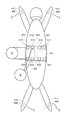
- FIG. 2 is a diagram illustrating an arrangement example of electrodes in the body fat measurement device according to the embodiment of the present invention.
- FIG. 2 shows a state where the upper limb electrode, the lower limb electrode, and the abdominal electrode are arranged.
- FIG. 2 is an example of electrode arrangement viewed from the back side of the subject.
- the body fat measuring device 1 includes an electrode belt 100 and a limb clip 400.
- the electrode belt 100 is formed by integrally forming the abdominal electrode pairs AP1, AP2, AP3, AP4 and the belt material 101.
- the abdominal electrode pair AP1 includes abdominal electrodes A11 and A21.
- the abdominal electrode pair AP2 includes abdominal electrodes A12 and A22.
- the abdominal electrode pair AP3 includes abdominal electrodes A13 and A23.
- the abdominal electrode pair AP4 includes abdominal electrodes A14 and A24.
- abdominal electrode pairs AP1, AP2, AP3, AP4 two pairs of electrodes are arranged in the body axis direction on the back of the abdomen of the subject, and each electrode pair is arranged in a direction substantially perpendicular to the body axis and spaced from each other. Is done.
- the abdominal electrode pair AP2 is arranged at a predetermined distance from an axis passing through the abdominal electrodes A11 and A21 of the abdominal electrode pair AP1.
- the distance between the electrodes of the abdominal electrode pairs AP1, AP2, AP3, AP4 is substantially equal.
- the distance between the abdominal electrodes A11 and A21 of the abdominal electrode pair AP1 and the distance between the abdominal electrodes A12 and A22 of the abdominal electrode pair AP2 are substantially equal.
- Each of the electrodes of the abdominal electrode pairs AP1, AP2, AP3, AP4 is arranged in alignment with the electrodes of the corresponding other electrode pairs in a direction substantially perpendicular to the body axis. That is, the abdominal electrodes A11, A12, A13, A14 are arranged in a line in a direction substantially perpendicular to the body axis.
- the abdominal electrodes A21, A22, A23, A24 are arranged in a line in a direction substantially perpendicular to the body axis.
- the abdominal electrode pairs AP1, AP2, AP3, AP4 may be arranged in a line in the body axis direction.
- the abdominal electrode pairs AP2, AP3, AP4 may be arranged on an axis passing through the abdominal electrodes A11, A21 of the abdominal electrode pair AP1.
- abdominal electrode pairs AP1, AP2 are arranged in a line in the body axis direction, and abdominal electrode pair AP1 is arranged at a position sandwiching abdominal electrode pair AP2.
- the abdominal electrode pair AP3, AP4 may be arranged in a line in the body axis direction, and the abdominal electrode pair AP3 may be arranged at a position sandwiching the abdominal electrode pair AP4.
- the limb clip 400 holds the upper limb electrodes H11 and H21 and the lower limb electrodes F11 and F21, and is attached to the surface of the wrist of the right hand, the surface of the wrist of the left hand, the surface of the ankle of the right foot, and the surface of the ankle of the left foot, respectively. Has been.
- the constant current generator 21 causes a current to flow between electrodes of an electrode pair (hereinafter also referred to as a current electrode pair) electrically connected to the constant current generator 21 by the terminal switching unit 22.
- the potential difference detection unit 23 detects a potential difference between electrodes of an electrode pair (hereinafter also referred to as a voltage electrode pair) electrically connected to the potential difference detection unit 23 by the terminal switching unit 22.
- the visceral fat mass calculation unit 16 calculates the visceral fat mass of the subject based on the potential difference between the electrodes of the voltage electrode pair detected by the potential difference detection unit 23.
- FIG. 3 is a flowchart that defines an operation procedure when the body fat measurement device according to the present embodiment measures the visceral fat mass.
- the processing shown in the flowchart of FIG. 3 is stored in advance in the memory unit 29 as a program, and the function of the visceral fat measurement processing is realized by the control unit 10 reading and executing this program.
- control unit 10 receives input of subject information including physique information (waist length) (step S2).
- the subject information received here is temporarily stored in the memory unit 29, for example.
- control unit 10 determines whether or not there is an instruction to start measurement (step S4). Control unit 10 waits for an instruction to start measurement (NO in step S4). When control unit 10 detects an instruction to start measurement (YES in step S4), it performs electrode setting (step S8).
- control unit 10 first performs an impedance Zt calculation process. That is, for example, the control unit 10 selects one pair of upper limb electrode H11, lower limb electrode F11 and one pair of upper limb electrode H21, lower limb electrode F21 as current electrode pairs, and selects an abdominal electrode pair AP1 as a voltage electrode pair.
- the terminal switching unit 22 electrically connects the pair of upper limb electrodes H11 and the lower limb electrodes F11 and the pair of upper limb electrodes H21 and the lower limb electrodes F21 to the constant current generation unit 21 based on the control of the control unit 10, and
- the abdominal electrode pair AP1 is electrically connected to the potential difference detection unit 23 (step S8).
- the terminal switching unit 22 disconnects the electrical connection between the non-selected electrode and the constant current generation unit 21 and the potential difference detection unit 23 based on the control of the control unit 10.
- the constant current generation unit 21 causes a current to flow from the upper limb to the lower limb based on the control of the control unit 10.
- the constant current generation unit 21 causes a current to flow from the upper limb electrode H11 and the upper limb electrode H21 to the lower limb electrode F11 and the lower limb electrode F21 (step S10).
- the terminal switching unit 22 is preferably configured to short-circuit the upper limb electrode H11 and the upper limb electrode H21 and to short-circuit the lower limb electrode F11 and the lower limb electrode F21.
- the constant current generation unit 21 and the terminal switching unit 22 may have a configuration in which a current flows from any one of the upper limb electrodes H11 and H21 to any one of the lower limb electrodes F11 and F21.
- the potential difference detection unit 23 detects a potential difference between the abdominal electrodes A11 and A21 of the abdominal electrode pair AP1 based on the control of the control unit 10 (step S12).
- the control unit 10 selects the abdominal electrode pairs AP2, AP3, AP4 as voltage electrode pairs in order. That is, the terminal switching unit 22 electrically connects the abdominal electrode pairs AP2, AP3, AP4 to the potential difference detection unit 23 in order based on the control of the control unit 10 (step S8). Then, the potential difference detection unit 23 sequentially detects the potential difference between the electrodes of the abdominal electrode pairs AP2, AP3, AP4 based on the control of the control unit 10 (step S12).
- the impedance calculation unit 12 completes the detection of the potential difference for all combinations of electrode pairs.
- the detection of the potential difference between the electrodes of the abdominal electrode pairs AP1, AP2, AP3, AP4 is completed (step Based on the current value supplied by the constant current generator 21 and the potential differences detected by the potential difference detector 23, impedances Zt1 to Zt4 are calculated (step S14).
- the values of the impedances Zt1 to Zt4 calculated by the impedance calculation unit 12 are temporarily stored in the memory unit 29, for example.
- the control unit 10 performs an impedance Zs calculation process. That is, the control unit 10 selects the abdominal electrode pair AP1 as the current electrode pair, and selects the abdominal electrode pair AP2 as the voltage electrode pair.
- the terminal switching unit 22 electrically connects the abdominal electrode pair AP1 to the constant current generating unit 21 and electrically connects the abdominal electrode pair AP2 to the potential difference detecting unit 23 based on the control of the control unit 10 (step). S16).
- the terminal switching unit 22 selectively electrically connects each abdominal electrode pair to the potential difference detection unit 23 based on the control of the control unit 10, and the unselected abdominal electrode pair, upper limb electrode, and lower limb electrode And the constant current generator 21 and the potential difference detector 23 are disconnected from each other.
- the constant current generation unit 21 causes a current to flow between the abdominal electrodes A11 and A21 of the abdominal electrode pair AP1 based on the control of the control unit 10 (step S18).
- the potential difference detector 23 detects a potential difference between the abdominal electrodes A12 and A22 of the abdominal electrode pair AP2 based on the control of the control unit 10 (step S20).
- the control unit 10 selects the abdominal electrode pairs AP3 and AP4 as voltage electrode pairs in order. That is, the terminal switching unit 22 electrically connects the abdominal electrode pairs AP3 and AP4 to the potential difference detection unit 23 in order based on the control of the control unit 10 (step S16).
- the potential difference detection unit 23 sequentially detects the potential difference between the electrodes of the abdominal electrode pair AP3 and AP4 based on the control of the control unit 10 (step S20).
- the control unit 10 selects the abdominal electrode pair AP2 as the current electrode pair, and selects the abdominal electrode pair AP1 as the voltage electrode pair. That is, the terminal switching unit 22 electrically connects the abdominal electrode pair AP2 to the constant current generation unit 21 and electrically connects the abdominal electrode pair AP1 to the potential difference detection unit 23 based on the control of the control unit 10. (Step S16).
- the constant current generation unit 21 causes a current to flow between the abdominal electrodes A12 and A22 of the abdominal electrode pair AP2 based on the control of the control unit 10 (step S18).
- the potential difference detection unit 23 detects a potential difference between the abdominal electrodes A11 and A21 of the abdominal electrode pair AP1 based on the control of the control unit 10 (step S20).
- the control unit 10 selects the abdominal electrode pairs AP3 and AP4 as voltage electrode pairs in order. That is, the terminal switching unit 22 electrically connects the abdominal electrode pairs AP3 and AP4 to the potential difference detection unit 23 in order based on the control of the control unit 10 (step S16).
- the potential difference detection unit 23 sequentially detects the potential difference between the electrodes of the abdominal electrode pair AP3 and AP4 based on the control of the control unit 10 (step S20).
- control unit 10 sequentially selects the abdominal electrode pairs AP3 and AP4 as current electrode pairs, and each of the abdominal electrode pairs AP3 and AP4 is the abdominal part of the abdominal electrode pairs AP1 to AP4 other than the current electrode pair.
- the electrode pairs are sequentially selected as voltage electrode pairs, and potential differences between the electrodes of the voltage electrode pairs are detected (steps S16 to S20).
- the impedance calculation unit 12 determines that the current value passed by the constant current generation unit 21 and the potential difference detection unit 23 Based on the detected potential differences, impedances Zs1 to Zs12 are calculated (step S22).
- the values of the impedances Zs1 to Zs12 calculated by the impedance calculation unit 12 are temporarily stored in the memory unit 29, for example.
- the visceral fat mass calculation unit 16 calculates the visceral fat area Sv based on the physique information (waist length) received by the control unit 10 in step S2, the impedances Zt1 to Zt4, and the impedances Zs1 to Zs12 ( Step S24).
- the visceral fat area Sv is calculated by the above formula (1).
- the average value of the four impedances Zt1 to Zt4 is the impedance in the equation (1).
- the average value of the twelve impedances Zs1 to Zs12 is substituted into the impedance Zs in equation (1).
- the subcutaneous fat mass calculation unit 17 calculates the subcutaneous fat area Ss based on the physique information (waist length) received by the control unit 10 in step S2 and the impedances Zs1 to Zs12 (step S26).
- the subcutaneous fat area Ss is calculated by the above equation (2).
- the average value of the twelve impedances Zs1 to Zs12 is expressed by the equation (2). Substituted for impedance Zs.
- the body fat mass calculation unit 14 calculates the lean body mass FFM based on the subject information (for example, height) input in step S2 and the impedances Zt1 to Zt4 (step S28).
- the lean mass FFM is calculated by the above equation (3).
- the average value of the four impedances Zt1 to Zt4 is expressed by the equation (3). Substituted for impedance Zt.
- the body fat mass calculation unit 14 calculates the body fat percentage based on the subject information (body weight) input in step S2 and the lean body mass FFM calculated in step S28 (step S30).
- the body fat percentage is calculated by the above equation (4).
- the display part 26 displays each measurement result based on control of the control part 10 (step S32).
- the body fat measurement device 1 ends the body fat measurement process.
- typical values of the impedances Zt1 to Zt4 are each about 5 ⁇ .
- typical values of the impedances Zs1 to Zs12 are each about 80 ⁇ .
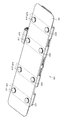
- FIGS. 4 and 5 are perspective views showing the structure of the electrode belt 100 used in the body fat measuring device
- FIG. 5 is a perspective view showing the structure of the abdominal electrode 200 provided in the electrode belt 100 used in the body fat measuring device.
- the electrode belt 100 is formed by integrally forming the abdominal electrode pairs AP1, AP2, AP3, AP4 and the belt material 101.
- An elastomeric material is used for the belt material 101, and a bellows structure is partially adopted so as to be easily deformed along the abdomen of the subject.
- the abdominal electrode pair AP1 includes abdominal electrodes A11 and A21, and the abdominal electrodes A11 and A21 are arranged with a predetermined gap in the body axis direction.
- the abdominal electrode pair AP2 also includes abdominal electrodes A12 and A22, and the abdominal electrodes A12 and A22 are arranged with a predetermined gap in the body axis direction.
- the abdominal electrode pair AP3 also includes abdominal electrodes A13 and A23, and the abdominal electrodes A13 and A23 are arranged with a predetermined gap in the body axis direction.
- the abdominal electrode pair AP4 also includes abdominal electrodes A14 and A24, and the abdominal electrodes A14 and A24 are arranged with a predetermined gap in the body axis direction.
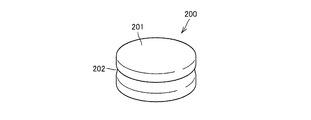
- FIG. 5 shows the structure of the abdominal electrode 200 used for the abdominal electrodes A11, A21, A12, A22, A13, A23, A14, and A24.
- the abdominal electrode 200 has a cylindrical shape, a diameter of about 23 mm, and a protruding height from the belt material 101 of about 6 mm.
- the abdominal part electrode 200 has a metal cylindrical electrode part 201, and an annular groove concave part 202 is provided in a waist part of the cylindrical electrode part 201.
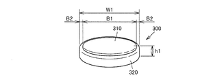
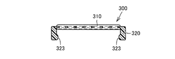
- FIGS. 6 and 7 are perspective views showing the structure of the abdominal electrode pad 300
- FIG. 7 is a plan view showing the structure of the abdominal electrode pad 300.
- the gel used in the following description is a lyophilic solute colloidal solution, which means a gel of a substance (jelly) having elasticity and low fluidity.
- the abdominal electrode pad 300 is provided with a circular conductive gel 310 and the conductive gel 310 so as to be electrically contactable with the abdominal electrode 200 and detachably attached to the abdominal electrode 200. And a cylindrical base member 320 having one end opened.
- a polypropylene resin material, an ABS resin, or the like is used for the base member 320.
- acrylic polymer gel, urethane gel, or the like is used as the conductive gel 310.
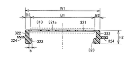
- the abdominal electrode pad 300 has an outer diameter (W1) of about ⁇ 26 mm and a height (h1) including the conductive gel 310 of about 7 mm. Further, in the surface portion of the abdominal electrode pad 300, the conductive gel 310 is held by the base member 320 so that the edge (region indicated by B2) of the base member 320 is exposed.
- the region where the conductive gel 310 is provided (the region indicated by B1) has a diameter of about 22 mm, and the exposed edge (the region indicated by B2) has a length of about 2 mm.
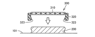
- FIGS. 8 is a cross-sectional view taken along line VIII-VIII in FIG. 7, and FIGS. 9 and 10 are first and second schematic views showing attachment of the abdominal electrode pad 300 to the abdominal electrode.
- a convex region 323 that protrudes inward in the radial direction is provided on the open end side of the cylindrical base member 320.
- region 323 may be provided in the continuous annular shape, and may be provided in several places discontinuously.
- the convex region 323 of the base member 320 is once elastically deformed so as to expand outward. Thereafter, the convex region 323 engages with the groove concave portion 202 of the abdominal electrode 200. Thereby, the abdominal electrode pad 300 is fixed to the abdominal electrode 200. At this time, the lower surface side of the conductive gel 310 provided on the abdominal electrode pad 300 contacts the upper surface portion of the abdominal electrode 200 so as to be electrically conductive.
- the base member 320 is picked and lifted with a finger.
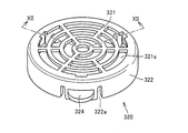
- FIGS. 11 is a first perspective view showing the structure of the base member 320 from the surface side
- FIG. 12 is a cross-sectional view taken along line XII-XII in FIG. 11
- FIG. 13 is a second view showing the structure of the base member 320 from the surface side
- FIG. 14 is a perspective view showing the structure of the base member 320 from the back side.
- the base member 320 has a cylindrical body 322 whose one end is open, and a polypropylene resin material, ABS resin, or the like is used.
- a cylindrical holding surface 321 provided with a plurality of openings 321a is provided on the other end side of the cylindrical body 322 on which the conductive gel 310 is held.
- the opening 321a formed in the holding surface 321 has a plurality of arc-shaped openings provided concentrically.
- the width of the opening 321a in the radial direction is about 2 mm, and the width of the holding surface 321 positioned between the openings 321a is about 1 mm.
- the conductive gel 310 is applied to the front surface side and the back surface side of the holding surface 321 using the opening 321a formed in this manner, and the conductive gel 310 is integrated with the base member 320 on the holding surface 321. Is held in.
- the total area of the openings 321a in the region where the conductive gel 310 is provided is 50 of the total area of the region where the conductive gel 310 is provided (the region indicated by B1 in FIG. 12). % Or better. Accordingly, when the conductive gel 310 is applied to the holding surface 321 of the base member 320, it becomes easy for the bubbles to escape from the opening, and the entrainment of the bubbles into the conductive gel 310 can be suppressed. Become. As a result, it is possible to prevent the thinning due to the time-dependent change of the conductive gel 310 at the bubble mixed portion, and to stabilize the measurement accuracy in the visceral fat measurement device.
- the protruding length (b) of the convex region 323 is about 0.5 mm. Further, the diameter (W1) of the base member 320 is about ⁇ 26 mm as described above, and the height (h2) of the base member is about 6 mm.
- a total of six slits 322a are provided on the outer peripheral surface of the cylindrical body 322 in the region where the convex region 323 is provided, and three finger hook portions 324 projecting outward in the radial direction to the region sandwiched between the slits 322a.
- region 323 mentioned above is provided in the internal peripheral surface of the cylindrical body 322 in which the finger hook part 324 is provided.
- the convex region 323 moves outward by elastically deforming the region sandwiched between the slits 322a by the finger hook portion 324, and the abdominal portion can be easily moved. It becomes possible to remove the electrode pad 300 from the abdominal electrode 200.
- region 323 and the finger hook part 324 is not limited to three, It is possible to provide one place, two places, or four places or more.
- a plurality of protrusions 321p are provided on the back side of the holding surface 321. As shown in FIG. 15, when the protrusion 321p is not provided, after the abdominal electrode pad 300 is attached to the abdominal electrode 200, the abdominal electrode pad 300 is pressed against the abdominal electrode 200 side (in FIG. 15). In the direction of arrow F), the conductive gel 310 is pushed out from the holding surface 321 and the conductive gel 310 collapses.
- the abdominal electrode pad 300 is pressed against the abdominal electrode 200 after the abdominal electrode pad 300 is attached to the abdominal electrode 200. Even when attached (in the direction of arrow F in FIG. 16), the protrusion 321p contacts the surface of the abdominal electrode 200 and suppresses the movement of the holding surface 321 to the abdominal electrode 200 side. As a result, it is possible to prevent the conductive gel 310 from being pushed out from the holding surface 321 and to prevent the conductive gel 310 from collapsing.
- FIG. 17 is a perspective view showing the structure of another base member
- FIG. 18 is a cross-sectional view taken along line XVIII-XVIII in FIG.
- the base member 320A also has a cylindrical body 322 that is open at one end, and is made of polypropylene resin material, ABS resin, or the like.
- a cylindrical holding surface 321 provided with a plurality of openings 321a is provided on the other end side of the cylindrical body 322 on which the conductive gel 310 is held.
- the opening 321a formed in the holding surface 321 has an opening form in which a plurality of circular openings are provided.
- the diameter of one opening 321a is about 2 mm, and the shortest distance between the openings 321a is about 1 mm.
- the conductive gel 310 is applied to the front surface side and the back surface side of the holding surface 321 by using the opening 321a formed in this way, and the conductive gel 310 is integrated with the base member 320A on the holding surface 321. Is held in.
- a convex region 323 that protrudes inward in the radial direction is provided.
- the protruding length (b) of the convex region 323 is about 0.5 mm.
- the diameter (W1) of the base member 320 is about ⁇ 26 mm as described above, and the height (h2) of the base member is about 6 mm.
- a plurality of slits 322a are provided on the outer peripheral surface of the cylindrical body 322, and a finger hook portion 324 having a plurality of convex portions extending in the circumferential direction is provided in a region sandwiched between the slits 322a.
- a finger hook portion 324 having a plurality of convex portions extending in the circumferential direction is provided in a region sandwiched between the slits 322a.
- the total area of the openings 321a in the region where the conductive gel 310 is provided is the region where the conductive gel 310 is provided (the region indicated by B1 in FIG. 18). 50) or more of the total area. Accordingly, when the conductive gel 310 is applied to the holding surface 321 of the base member 320A, it is easy for the bubbles to escape from the opening, and the entrainment of the bubbles in the conductive gel 310 can be suppressed. Become. As a result, it is possible to prevent the thinning due to the time-dependent change of the conductive gel 310 at the bubble mixed portion, and to stabilize the measurement accuracy in the visceral fat measurement device.
- FIGS. 19 is a perspective view showing the structure of the conductive gel sheet 310A used for the abdominal electrode pad 300B
- FIG. 20 is a perspective view showing the structure of the base member 320B
- FIG. 21 is a cross section showing the structure of the abdominal electrode pad 300B.
- the abdominal electrode pad 300B includes a conductive gel sheet 310A and a base member 320B. As shown in FIG. 19, in the conductive gel sheet 310A, the conductive gel 310 is applied in a circular shape on both surfaces of a sheet-like member 311 using a fiber member such as a circular nonwoven fabric. The peripheral edge of the sheet-like member 311 is exposed from the conductive gel 310.
- the base member 320B includes a cylindrical body 322 whose both ends are open and an annular cap 321C having an opening 321a.
- the cylindrical body 322 and the cap 321C are connected by an elastically deformable connecting piece 325. Yes.
- the cylindrical body 322, the cap 321C, and the connecting piece 325 are all integrally formed of a polypropylene resin material, ABS resin, or the like.
- the cap 321C is provided with three engagement pieces 321b protruding in the axial direction. Further, the cylindrical body 322 is provided with an engaging recess 322c that is detachably attached to the engaging piece 321b at a position corresponding to the engaging piece 321b. A convex region 323 that protrudes inward in the radial direction is provided on the inner peripheral surface of the cylindrical body 322 opposite to the side where the cap 321C is provided.
- the conductive gel sheet 310A is sandwiched between the upper end portion 322t of the cylindrical body 322 and the flange portion 321t provided on the cap 321C so that the exposed peripheral portion of the exposed sheet-like member 311 is sandwiched between the base member 320B. It is held (see FIG. 21).
- the external dimensions of the abdominal electrode pad 300B are the same as those of the abdominal electrode pad 300 described above, the protruding length (b) of the convex region 323 is about 0.5 mm, and the diameter (W1) of the base member 320B is about ⁇ 26 mm.
- the height (h2) of the base member is 6 mm, and the height (h1) of the abdominal electrode pad 300B is 7 mm.
- the conductive gel sheet 310A As described above, by using the conductive gel sheet 310A, it is possible to discard the conductive gel sheet 310A after use and reuse the base member 320B.
- a fiber having a large mesh is used for the sheet-like member 311 of the conductive gel sheet 310A, and the total area of the openings of the eyes is at least a region where the conductive gel 310 is provided on the sheet-like member 311 (shown by B1 in FIG. 21).
- the total area of the region is preferably 50% or more. Accordingly, when the conductive gel 310 is applied to the sheet-like member 311, the bubbles can easily escape from the mesh, and the entrainment of the bubbles into the conductive gel 310 can be suppressed. As a result, it is possible to prevent the thinning due to the time-dependent change of the conductive gel 310 at the bubble mixed portion, and to stabilize the measurement accuracy in the visceral fat measurement device.
- the abdominal electrode pads 300 and 300B in the present embodiment since the conductive gel 310 is held in advance by the base members 320, 320A, and 320B, the abdominal electrode pads 300 and 300B are attached to the abdominal electrode. It is possible to easily apply the conductive gel 310 to the abdominal electrode 200 only by being attached to 200.
- the wiping work of the conductive gel 310 attached to the subject is also facilitated.
- wiping work of the conductive gel 310 attached to the abdominal electrode 200 is also facilitated.
- the application position and amount of the conductive gel 310 attached to the subject are constant, the stability of contact resistance reduction and the constant distance between the electrodes can be ensured.
- the abdominal electrode pad 300 for each electrode of the body fat measuring device described in the present embodiment the reliability of the measurement result in the body fat measuring device can be improved.
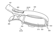
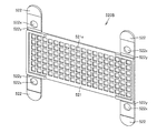
- FIG. 22 is a view showing the structure of the limb clip 400.
- the limb clip 400 has a first sandwiching clip 401 and a second sandwiching clip 402.
- the 1st clamping clip 401 and the 2nd clamping clip 402 have the loose S character shape used as symmetry.
- the first clamping clip 401 and the second clamping clip 402 are connected by an elastic clip 403 so as to be openable and closable in the direction of arrow S in the figure.
- the curved portion of the second sandwiching clip 402 facing the first sandwiching clip 401 is attached with a thin plate-like upper and lower limb electrode 404 made of stainless steel that functions as the upper limb electrodes H11 and H21 or the lower limb electrodes F11 and F21. Yes.
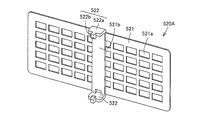
- FIGS. 23 is a perspective view showing the structure of the upper / lower limb electrode pad 500
- FIG. 24 is a sectional view taken along the line XXIV-XXIV in FIG. 23
- FIG. 25 is a sectional view taken along the line XXV-XXV in FIG. is there.
- this upper limb / lower limb electrode pad 500 holds a rectangular conductive gel 510 and this conductive gel 510 so as to be in electrical contact with the upper limb / lower limb electrode 404.
- a substantially rectangular base member 520 that is detachably attached to the upper limb / lower limb electrode 404 is provided.
- a polypropylene resin material, an ABS resin, or the like is used for the base member 520.
- acrylic polymer gel, urethane gel, or the like is used as the conductive gel 510.
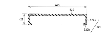
- the upper limb / lower limb electrode pad 500 has a maximum length (W21) of about 77 mm, a maximum width (W22) of about 38 mm, and a height (h21) including the conductive gel 510 of about 9 mm.
- W21 maximum length
- W22 maximum width
- h21 height
- the conductive gel 510 is held by the base member 520 so that the edge portions (regions indicated by B12 and B22) of the base member 520 are exposed.
- the region where the conductive gel 510 is provided (the region indicated by B11, B21) is B73 of about 73 mm, B21 is about 30 mm, and the exposed edge (the region indicated by B22, B12) is both B22 and B12. About 2 mm.
- Engagement regions 522 are provided at the four corners of the base member 520.
- the engagement region 522 has an arm portion 522a depending from the base member 520 and an engagement piece 522b extending inward from the arm portion 522a in parallel to the base member 520.
- FIG. 26 is a perspective view showing a state where the upper limb / lower limb electrode pad is attached to the upper limb / lower limb electrode
- FIG. 27 is a sectional view taken along line XXVII-XXVII in FIG.
- the upper limb / lower limb electrode pad 500 is attached to the upper limb / lower limb electrode 404.
- the lower surface side of the conductive gel 510 provided on the upper limb / lower limb electrode pad 500 comes into contact with the upper surface portion of the upper limb / lower limb electrode 404 so as to be electrically conductive.
- the base member 520 is picked and pulled away with a finger.
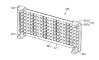
- FIGS. 28 is a perspective view showing the structure of the base member 520
- FIG. 29 is a perspective view showing another structure of the base member 520.
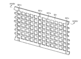
- the base member 520 has a substantially rectangular shape as a whole, and a polypropylene resin material, an ABS resin, or the like is used.
- the holding surface 521 on which the conductive gel 510 is held is provided with a plurality of rectangular openings 521a in a matrix shape, and has a net shape.
- the opening 521a formed in the holding surface 521 is a rectangular opening having a side of about 3 mm to 5 mm, and the interval between the openings 521a is about 1 mm to 2 mm.
- the conductive gel 510 is applied to the front surface side and the back surface side of the holding surface 521 using the opening 521a formed in this way, and the conductive gel 510 is integrated with the base member 520 on the holding surface 521. Is held in.
- engagement areas 522 having the arm portions 522a and the engagement pieces 522b are provided.
- the engagement area 522 is elastically deformed by the finger hook portion 523, and the upper limb / lower limb electrode pad 500 is easily deformed. It can be removed from the lower limb electrode 404.
- the total area of the openings 521a in the region where the conductive gel 510 is provided is the total area of the region where the conductive gel 510 is provided (the region indicated by B11 and B21 in FIG. 23). It may be 50% or more of the total area.
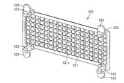
- FIG. 30 is a perspective view showing the structure of another base member.
- the base member 520 ⁇ / b> A has an opening 521 a having an opening area larger than the opening 521 a provided in the base member 520, and the engaging region 522 is a reinforcing portion 521 b provided in the central portion of the holding surface 521. Two places are provided at both ends of the. Also with this configuration, the upper limb / lower limb electrode pad 500 is held by the upper limb / lower limb electrode 404 so as to embrace the upper limb / lower limb electrode 404 and the second holding clip 402 using the engagement region 522 provided in the base member 520A. Can be attached to.
- the total area of the openings 521a in the region where the conductive gel 510 is provided is the region where the conductive gel 510 is provided (FIG. 23). (Corresponding to the regions indicated by B11 and B21) of 50% or more of the total area.
- FIG. 31 is a perspective view showing still another structure of the base member 520B
- FIG. 32 is a cross-sectional view showing a structure for attaching the base member 520B to the second holding clip 402.
- the basic structure of base member 520B is the same as base member 520 described above, and the difference is in the structure of engagement region 522.
- the engagement region 522 in the base member 520B is formed so as to be flush with the holding surface 521, and a thin portion 522y constituting a fragile region is provided in a streak shape at a connecting portion with the holding surface 521. Further, an engagement hole 522x is provided in the engagement region 522.
- An engagement protrusion 405 for engaging with an engagement hole 522x provided in the engagement region 522 is provided on the side surface of the second sandwiching clip 402 in advance.
- the engagement region 522 is bent along the thin portion 522y, and the engagement hole 522x is engaged with the engagement protrusion 405.
- the productivity of the base member 520B can be improved by forming the base member 520B into a flat shape including the engagement region 522.
- the base member 520B has less unevenness, so that a highly airtight packing method can be performed.
- the engagement hole 522x provided in the engagement region 522 the conductive gel 510 can be pressed against the upper limb / lower limb electrode 404.
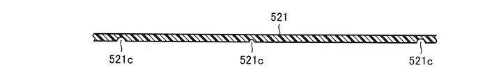
- the cross-sectional shape of the groove 521c is not limited to the U-shaped groove shown in FIG. 34 but may be a V-shaped groove.
- the groove 521c in a direction (short direction) perpendicular to the longitudinal direction of the holding surface 521, when the upper limb / lower limb electrode pad 500 is attached to the upper limb / lower limb electrode 404, the second It becomes easy to bend along the curved shape of the holding clip 402, and the contact of the conductive gel 510 to the upper limb / lower limb electrode 404 can be improved.
- the total area of the openings 521a in the region where the conductive gel 510 is provided is the region where the conductive gel 510 is provided (FIG. 23). (Corresponding to the regions indicated by B11 and B21) of 50% or more of the total area.
- FIG. 35 is a perspective view showing still another structure of the base member 520C.
- the basic structure of the base member 520C is the same as that of the base member 520 described above, and the difference is in the shape and arrangement of the opening 521a and the structure of the engagement region 522.
- the opening 521a has a triangular shape, and is arranged so that the hypotenuses of adjacent triangles are parallel to each other in the vertical direction in the figure, and has a net-like shape.
- the holding surface 521 is provided with a plurality of protrusions 521p similar to the protrusions 321p described in FIG.
- the holding surface 521 is provided with a pair of streak-like convex walls 521x so as to define a region where the conductive gel 510 is provided (regions indicated by B11 and B21 in FIG. 35).
- the engaging region 522 in the base member 520C is connected to the holding surface 521 with the stepped portion 522d and the thin portion 522y constituting the weak region interposed therebetween.
- An engagement hole 522x is provided in the engagement region 522.
- a region where the engagement region 522 of the holding surface 521 is connected region outside the region indicated by B11 in FIG. 35
- a thick portion 522z having a thickness larger than the thickness of the holding surface 521 is provided.
- the mounting structure of the base member 520C to the second holding clip 402 is the same as the base member 520B described in FIG.
- the total area of the openings 521a in the region where the conductive gel 510 is provided is the region where the conductive gel 510 is provided (FIG. 35). (Corresponding to the regions indicated by B11 and B21) of 50% or more of the total area.
- FIG. 36 shows a pattern of the opening 521a employed in the base members 520, 520A, and 520B.
- the flow of the conductive gel 510 introduced from the opening 521a is considered to be as indicated by an arrow G1 in the figure.
- the region surrounded by the corner of the opening 521a of the holding surface 521 the region having the same distance from the end of the opening
- bubbles are entrained in the conductive gel 510.
- relatively large bubbles Ba may remain in the conductive gel 510.
- FIG. 37 shows a pattern of the opening 521a employed in the base member 520C.
- the opening 521a has a triangular shape, and is arranged so that oblique sides of adjacent triangles are parallel to each other in the vertical direction in the figure.
- the area of the same distance from the end of the opening is reduced, and more bubble escape areas can be formed.
- entrainment of bubbles in the conductive gel 510 is improved, and the remaining of bubbles in the conductive gel 510 can be suppressed.
- the upper limb / lower limb electrode pad 500 in the present embodiment since the conductive gel 510 is held in advance by the base member 520, the upper limb / lower limb electrode pad 500 is used as the upper limb / lower limb electrode 404.
- the conductive gel 510 can be easily applied to the upper limb / lower limb electrode 404 only by wearing.
- the wiping work of the conductive gel 510 attached to the subject is also facilitated.
- the wiping operation of the conductive gel 510 attached to the upper limb / lower limb electrode 404 is facilitated.
- the application position and amount of the conductive gel 510 attached to the subject are constant, the stability of contact resistance reduction and the constant distance between the electrodes can be ensured. Thereby, it becomes possible to improve the reliability of the measurement result in the body fat measurement device by using the upper / lower limb electrode pad 500 for each electrode of the body fat measurement device described in the present embodiment.
- the electrode pad attached to the electrode used in the body fat measuring device is described.
- the electrode pad is not limited to the electrode used in the body fat measuring device. Absent.
- the electrode pad according to the present invention can be applied to electrodes used in electrocardiograms, electromyograms, low-frequency massagers, EMS (Electro Muscle Stimulation), brain waveform measuring devices, and the like.
Landscapes
- Health & Medical Sciences (AREA)
- Life Sciences & Earth Sciences (AREA)
- Biomedical Technology (AREA)
- Molecular Biology (AREA)
- Radiology & Medical Imaging (AREA)
- Biophysics (AREA)
- Pathology (AREA)
- Engineering & Computer Science (AREA)
- Nuclear Medicine, Radiotherapy & Molecular Imaging (AREA)
- Heart & Thoracic Surgery (AREA)
- Medical Informatics (AREA)
- Physics & Mathematics (AREA)
- Surgery (AREA)
- Animal Behavior & Ethology (AREA)
- General Health & Medical Sciences (AREA)
- Public Health (AREA)
- Veterinary Medicine (AREA)
- Measurement And Recording Of Electrical Phenomena And Electrical Characteristics Of The Living Body (AREA)
- Electrotherapy Devices (AREA)
Abstract
The electrode pad that is fitted on an electrode (A11-A14, A21-A24, 404) is provided with conductive gel (310, 510) and a base (320, 320A, 320B, 520, 520A, 520B), which holds the conductive gel (310, 510) so as to allow contact with the electrode (A11-A14, A21-A24, 404), and is provided to allow attachment to and detachment from the electrode (A11-A14, A21-A24, 404).
Description
この発明は、生体に接触される電極に装着される電極用パッドに関する。
The present invention relates to an electrode pad to be attached to an electrode that comes into contact with a living body.
生体に接触される電極は、生体への密着性および皮膚追従性を高める観点から、導電性を有する含水状の流動性の高いゲル(以下、単に、流動性導電性ゲル(通称「ジェル」)と称する)を電極の表面に塗布している。これにより、電極と生体との間の接触抵抗を低減して、生体からの電気信号の測定精度の向上を図っている。
From the viewpoint of improving the adhesion to the living body and the skin followability, the electrode that is in contact with the living body is a water-containing highly fluid gel having conductivity (hereinafter simply referred to as a fluid conductive gel (commonly referred to as “gel”). Is applied to the surface of the electrode. Thereby, the contact resistance between an electrode and a biological body is reduced, and the improvement of the measurement precision of the electrical signal from a biological body is aimed at.
なお、「ゲル」とは、通常、親液性溶質のコロイド溶液であって、弾性力を有し流動性が小さい(ゼリー状)物質を意味する。したがって、本明細書において、単に「導電性ゲル」と示す物質は、通常の弾性力を有し流動性が小さい(ゼリー状)物質を意味し、「流動性導電性ゲル」は、弾力性を有さない流動性に富んだ物質を意味する。
It should be noted that the “gel” usually means a lyophilic solute colloidal solution having elasticity and small fluidity (jelly-like). Therefore, in the present specification, a substance simply indicated as “conductive gel” means a substance having a normal elastic force and low fluidity (jelly-like), and “flowable conductive gel” means elasticity. It means a substance with high fluidity that you do not have.
しかし、測定前においては、チューブを用いて流動性導電性ゲルを電極ごとに塗布する必要がある。また、測定後には、電極表面および生体から流動性導電性ゲルを拭き取る作業が必要となる。この流動性導電性ゲルの塗布および拭き取り作業は、測定者に対して煩わしいものである。
However, before measurement, it is necessary to apply a fluid conductive gel to each electrode using a tube. Further, after the measurement, it is necessary to wipe off the fluid conductive gel from the electrode surface and the living body. The operation of applying and wiping the fluid conductive gel is troublesome for the measurer.
なお、特開平04-244171号公報(特許文献1)および特開平04-303415号公報(特許文献2)には、生体に接触させる電極の表面に流動性導電性ゲルを設けた生体用電極が開示されている。
In Japanese Patent Application Laid-Open No. 04-244171 (Patent Document 1) and Japanese Patent Application Laid-Open No. 04-303415 (Patent Document 2), there is a living body electrode in which a fluid conductive gel is provided on the surface of an electrode to be brought into contact with the living body. It is disclosed.
この発明が解決しようとする課題は、流動性導電性ゲルを電極の表面に用いた場合に、各電極表面への流動性導電性ゲルの塗布作業が煩わしい点、電極表面および生体から流動性導電性ゲルを拭き取る作業が煩わしい点にある。
The problem to be solved by the present invention is that, when a fluid conductive gel is used on the surface of the electrode, it is troublesome to apply the fluid conductive gel to the surface of each electrode. The work of wiping off the gel is troublesome.
この発明の目的は、上記課題を解決することにあり、流動性が小さい導電性ゲルを電極の表面に用いた場合でも、各電極への導電性ゲルの塗布作業の容易化、電極表面および生体からの導電性ゲルの拭き取り作業の容易化が可能となる構造を備える電極用パッドを提供することにある。
An object of the present invention is to solve the above-described problem. Even when a conductive gel having low fluidity is used on the surface of the electrode, the application of the conductive gel to each electrode is facilitated, the electrode surface, and the living body. It is an object to provide an electrode pad having a structure capable of facilitating the wiping operation of the conductive gel from the substrate.
この発明に基づいた電極用パッドにおいては、電極に装着される電極用パッドであって、導電性ゲルと、上記導電性ゲルを上記電極に対して接触可能に保持するとともに、上記電極に対して着脱可能に設けられるベース部材とを備える。なお、ここでの「導電性ゲル」は、上記したように、流動性導電性ゲルとは異なり、親液性溶質のコロイド溶液であって、弾性力を有し流動性が小さい(ゼリー状)物質のゲルを意味している。
The electrode pad according to the present invention is an electrode pad to be attached to the electrode, and holds the conductive gel and the conductive gel so as to be in contact with the electrode. A detachable base member. As described above, the “conductive gel” here is a colloidal solution of a lyophilic solute, unlike the fluid conductive gel, and has elasticity and low fluidity (jelly-like). Means a gel of matter.
他の形態においては、上記ベース部材は、開口部を有する保持面を含み、上記導電性ゲルは、上記保持面において上記ベース部材と一体となるように保持されている。
In another embodiment, the base member includes a holding surface having an opening, and the conductive gel is held on the holding surface so as to be integrated with the base member.
他の形態においては、上記ベース部材の、上記導電性ゲルが設けられる領域における上記開口部の合計面積は、上記導電性ゲルが設けられる領域の全面積の50%以上である。
In another embodiment, the total area of the openings in the region where the conductive gel is provided of the base member is 50% or more of the total area of the region where the conductive gel is provided.
他の形態においては、上記ベース部材の、少なくとも上記導電性ゲルが設けられる領域は、網状部材である。
In another embodiment, at least a region where the conductive gel is provided in the base member is a mesh member.
他の形態においては、上記ベース部材の、少なくとも上記導電性ゲルが設けられる領域は、繊維状部材である。
In another embodiment, at least a region of the base member where the conductive gel is provided is a fibrous member.
他の形態においては、上記導電性ゲルは、上記ベース部材の縁部が露出するように上記ベース部材に保持されている。
In another embodiment, the conductive gel is held on the base member so that the edge of the base member is exposed.
他の形態においては、上記ベース部材は、弾性変形することにより上記電極に対して着脱可能とする係合領域を含む。
In another embodiment, the base member includes an engagement region that can be attached to and detached from the electrode by elastic deformation.
他の形態においては、上記ベース部材は、当該電極用パッドを上記電極から取り外す際に使用者の指を係合させるための指掛かり部をさらに備える。
In another embodiment, the base member further includes a finger hook portion for engaging a user's finger when removing the electrode pad from the electrode.
他の形態においては、上記ベース部材は、ポリプロピレン系樹脂材料である。
他の形態においては、上記導電性ゲルは、アクリル系高分子ゲル、または、電解液を含有するウレタン系ゲルである。 In another embodiment, the base member is a polypropylene resin material.
In another embodiment, the conductive gel is an acrylic polymer gel or a urethane gel containing an electrolytic solution.
他の形態においては、上記導電性ゲルは、アクリル系高分子ゲル、または、電解液を含有するウレタン系ゲルである。 In another embodiment, the base member is a polypropylene resin material.
In another embodiment, the conductive gel is an acrylic polymer gel or a urethane gel containing an electrolytic solution.
他の形態においては、上記電極は、内臓脂肪測定用装置に用いられる電極である。
In another embodiment, the electrode is an electrode used in a visceral fat measurement device.
この発明に基づいた電極用パッドによれば、流動性が小さい導電性ゲルを電極の表面に用いた場合でも、各電極への導電性ゲルの塗布作業の容易化、電極表面および生体からの導電性ゲルの拭き取り作業の容易化が可能となる構造を備える電極用パッドを提供することにある。
According to the electrode pad based on the present invention, even when a conductive gel having low fluidity is used on the surface of the electrode, the application work of the conductive gel to each electrode is facilitated, the conductivity from the electrode surface and the living body is improved. It is an object of the present invention to provide an electrode pad having a structure capable of facilitating the wiping operation of the conductive gel.
以下、この発明に基づいた実施の形態における電極用パッドについて図面を参照して詳細に説明する。なお、以下に説明する各実施の形態において、個数、量などに言及する場合、特に記載がある場合を除き、本発明の範囲は必ずしもその個数、量などに限定されない。また、以下に複数の実施の形態が存在する場合、特に記載がある場合を除き、各々の実施の形態の構成を適宜組み合わせることは、当初から予定されている。各図中、同一符号は同一または相当部分を指し、重複する説明は繰返さない場合がある。
Hereinafter, an electrode pad according to an embodiment of the present invention will be described in detail with reference to the drawings. In each embodiment described below, when referring to the number, amount, and the like, the scope of the present invention is not necessarily limited to the number, amount, and the like unless otherwise specified. In addition, when there are a plurality of embodiments below, it is planned from the beginning to appropriately combine the configurations of the embodiments unless otherwise specified. In the drawings, the same reference numerals indicate the same or corresponding parts, and redundant description may not be repeated.
以下に示す実施の形態においては、内臓脂肪量のみならず、全身の脂肪量および身体の特定部位別の脂肪量(上肢および下肢それぞれの脂肪量、体幹の脂肪量ならびに腹部における皮下脂肪量等)を測定することが可能に構成された体脂肪測定装置を例示して説明を行なう。すなわち、「体脂肪測定装置」は「内臓脂肪測定用装置」を含む。
In the embodiment described below, not only the visceral fat mass but also the total body fat mass and the fat mass of each specific part of the body (the fat mass of each of the upper and lower limbs, the fat mass of the trunk, the subcutaneous fat mass in the abdomen, etc. ) Will be described as an example of a body fat measuring device configured to be able to measure. That is, the “body fat measuring device” includes “a visceral fat measuring device”.
なお、「腹部」とは、体幹部のうちの胸部を除く部分である。また、「腹部より離れた部位」とは、上腕、前腕、手首および手指からなる上肢と、横隔膜より所定の距離(たとえば略10cm)以上離れた胸部と、肩、首および頭部を含む上体と、大腿、下腿、足首および足指からなる下肢とを含む。また、「体軸」とは、被験者の腹部の横断面に対し略垂直な方向の軸である。また、「腹部前面」とは、被験者の腹部のうち、被験者を正面から観察した場合に視認可能な部分を含む。たとえば、被験者の腹部のうち、被験者のへそおよび背骨を通るとともに被験者の体軸と垂直な軸に沿って、被験者をへそ側から観察した場合に視認可能な部分を含む。また、「腹部背面」とは、被験者の腹部のうち、被験者を後ろから観察した場合に視認可能な部分を含む。たとえば、被験者の腹部のうち、被験者のへそおよび背骨を通るとともに被験者の体軸と垂直な軸に沿って、被験者を背骨側から観察した場合に視認可能な部分を含む。
The “abdomen” is the portion of the trunk that excludes the chest. In addition, the “part away from the abdomen” means the upper limb including the upper arm, the forearm, the wrist and the fingers, the chest separated from the diaphragm by a predetermined distance (for example, approximately 10 cm) or more, and the upper body including the shoulder, the neck and the head. And lower limbs composed of thighs, lower legs, ankles and toes. The “body axis” is an axis in a direction substantially perpendicular to the cross section of the subject's abdomen. The “abdomen front surface” includes a portion of the abdomen of the subject that is visible when the subject is observed from the front. For example, a portion of the abdomen of the subject that is visible when the subject is observed from the navel side along an axis perpendicular to the subject's body axis while passing through the subject's navel and spine is included. Further, the “abdominal back surface” includes a portion of the abdomen of the subject that is visible when the subject is observed from behind. For example, it includes a portion of the abdomen of the subject that is visible when the subject is observed from the spine side along an axis perpendicular to the subject's body axis while passing through the subject's navel and spine.
[体脂肪測定装置]
図1は、本実施の形態における体脂肪測定装置の機能ブロック図である。まず、この図1を参照して、体脂肪測定装置の構成について説明する。 [Body fat measuring device]
FIG. 1 is a functional block diagram of the body fat measurement device according to the present embodiment. First, the configuration of the body fat measurement device will be described with reference to FIG.
図1を参照して、体脂肪測定装置1は、制御部10と、定電流生成部21と、端子切替部22と、電位差検出部23と、体格情報計測部24と、被験者情報入力部25と、表示部26と、操作部27と、電源部28と、メモリ部29と、複数の電極とを主として備えている。制御部10は、演算処理部11を含む。
With reference to FIG. 1, the body fat measurement device 1 includes a control unit 10, a constant current generation unit 21, a terminal switching unit 22, a potential difference detection unit 23, a physique information measurement unit 24, and a subject information input unit 25. A display unit 26, an operation unit 27, a power supply unit 28, a memory unit 29, and a plurality of electrodes. The control unit 10 includes an arithmetic processing unit 11.
体脂肪測定装置1は、複数の電極として、被験者の腹部背面に装着される腹部電極対AP1~AP4と、被験者の上肢に装着される上肢電極H11,H21と、被験者の下肢に装着される下肢電極F11,F21とを備えている。
The body fat measurement device 1 includes, as a plurality of electrodes, abdominal electrode pairs AP1 to AP4 attached to the back of the abdomen of the subject, upper limb electrodes H11 and H21 attached to the upper limb of the subject, and a lower limb attached to the lower limb of the subject. Electrodes F11 and F21 are provided.
制御部10は、たとえばCPU(Central Processor Unit)によって構成され、体脂肪測定装置1の全体的な制御を行なう。具体的には、制御部10は、上述した各種機能ブロックに対して指令を送出したり、得られた情報に基づいて各種の演算処理を行なったりする。このうち各種の演算処理については、制御部10に設けられた演算処理部11によって行なわれる。
The control unit 10 is configured by a CPU (Central Processor Unit), for example, and performs overall control of the body fat measurement device 1. Specifically, the control unit 10 sends commands to the various functional blocks described above and performs various arithmetic processes based on the obtained information. Among these, various arithmetic processes are performed by the arithmetic processing unit 11 provided in the control unit 10.
腹部電極対AP1~AP4は、それぞれ体軸方向に被験者の腹部背面の表面に装着される。上肢電極H11,H21は、好適には右手の手首の表面と左手の手首の表面とにそれぞれ装着される。下肢電極F11,F21は、好適には右足の足首の表面と左足の足首の表面とにそれぞれ装着される。腹部電極対AP1~AP4、上肢電極H11,H21、および下肢電極F11,F21は、それぞれ端子切替部22と電気的に接続されている。
The abdominal electrode pairs AP1 to AP4 are attached to the surface of the back of the subject's abdomen in the body axis direction. The upper limb electrodes H11 and H21 are preferably mounted on the surface of the wrist of the right hand and the surface of the wrist of the left hand, respectively. The lower limb electrodes F11 and F21 are preferably mounted on the ankle surface of the right foot and the ankle surface of the left foot, respectively. The abdominal electrode pairs AP1 to AP4, the upper limb electrodes H11 and H21, and the lower limb electrodes F11 and F21 are electrically connected to the terminal switching unit 22, respectively.
端子切替部22は、たとえば複数のリレー回路によって構成される。端子切替部22は、制御部10から受けた指令に基づいて、上述した複数の電極の中から選択した特定の電極対と定電流生成部21とを電気的に接続するとともに、上述した複数の電極の中から選択した特定の電極対と電位差検出部23とを電気的に接続する。
The terminal switching unit 22 is constituted by a plurality of relay circuits, for example. The terminal switching unit 22 electrically connects the specific electrode pair selected from the plurality of electrodes described above and the constant current generation unit 21 based on the command received from the control unit 10, and A specific electrode pair selected from the electrodes and the potential difference detection unit 23 are electrically connected.
これにより、端子切替部22によって定電流生成部21と電気的に接続された電極対が定電流印加電極対として機能するようになるとともに、端子切替部22によって電位差検出部23と電気的に接続された電極対が電位差検出電極対として機能するようになる。端子切替部22による電気的な接続は、測定動作中において種々切り替えられる。
As a result, the electrode pair electrically connected to the constant current generating unit 21 by the terminal switching unit 22 functions as a constant current applying electrode pair, and is electrically connected to the potential difference detecting unit 23 by the terminal switching unit 22. The electrode pair thus formed functions as a potential difference detection electrode pair. Various electrical connections by the terminal switching unit 22 are switched during the measurement operation.
定電流生成部21は、制御部10から受けた指令に基づいて定電流を生成し、生成した定電流を端子切替部22に供給する。定電流生成部21は、たとえば、体組成情報を測定するために好適に使用される高周波電流(たとえば、50kHz,500μA)を供給する。これにより、端子切替部22によって定電流生成部21と電気的に接続された電極対、すなわち定電流印加電極対を介して定電流が被験者に印加されることになる。
The constant current generation unit 21 generates a constant current based on a command received from the control unit 10 and supplies the generated constant current to the terminal switching unit 22. The constant current generator 21 supplies, for example, a high-frequency current (for example, 50 kHz, 500 μA) that is preferably used for measuring body composition information. As a result, a constant current is applied to the subject via the electrode pair electrically connected to the constant current generating unit 21 by the terminal switching unit 22, that is, the constant current applying electrode pair.
電位差検出部23は、端子切替部22によって電位差検出部23と電気的に接続された電極対、すなわち電位差検出電極対の電極間における電位差を検出し、検出した電位差を制御部10へ出力する。これにより、定電流が被験者に印加された状態における電位差検出電極対の電極間の電位差が検出されることになる。
The potential difference detection unit 23 detects a potential difference between the electrodes of the electrode pair electrically connected to the potential difference detection unit 23 by the terminal switching unit 22, that is, the potential difference detection electrode pair, and outputs the detected potential difference to the control unit 10. Thereby, the potential difference between the electrodes of the potential difference detection electrode pair in a state where the constant current is applied to the subject is detected.
体格情報計測部24および被験者情報入力部25は、制御部10の演算処理部11において行なわれる演算処理に利用される被験者情報を得るための部位である。ここで、被験者情報とは、被験者に関する情報を意味し、たとえば年齢、性別および体格情報等の情報のうち、少なくともいずれか1個を含む。また、体格情報とは、被験者の、身体の特定の部位におけるサイズに関する情報、たとえば、ウエスト長(腹部周長)、腹部横幅および腹部厚み等のうちの少なくともいずれか1個を含む情報と、身長および体重等の情報とを含む。体格情報計測部24は、被験者の体格情報を自動計測する部位であり、計測した体格情報を制御部10へ出力する。一方、被験者情報入力部25は、被験者情報を入力するための部位であり、入力された被験者情報を制御部10へ出力する。
The physique information measuring unit 24 and the subject information input unit 25 are parts for obtaining subject information used for the arithmetic processing performed in the arithmetic processing unit 11 of the control unit 10. Here, the subject information means information about the subject, and includes at least one of information such as age, sex, and physique information. The physique information is information on the size of a specific part of the body of the subject, for example, information including at least one of waist length (abdominal circumference), abdominal width and abdominal thickness, and height And information such as weight. The physique information measuring unit 24 is a part that automatically measures the physique information of the subject, and outputs the measured physique information to the control unit 10. On the other hand, the subject information input unit 25 is a part for inputting subject information, and outputs the input subject information to the control unit 10.
なお、図1に示される機能ブロック図においては、体格情報計測部24および被験者情報入力部25の両方が体脂肪測定装置1に設けられた場合を例示しているが、これら体格情報計測部24および被験者情報入力部25は、必ずしも必須の構成ではない。これら体格情報計測部24および/または被験者情報入力部25を設けるか否かについては、制御部10の演算処理部11において行なわれる演算処理に利用される被験者情報の種類に基づいて適宜選択される。また、被験者情報のうち、体格情報については、体格情報計測部24で自動計測を行なうように構成してもよいし、被験者情報入力部25において被験者自らが体格情報を入力する構成としてもよい。
The functional block diagram shown in FIG. 1 illustrates the case where both the physique information measurement unit 24 and the subject information input unit 25 are provided in the body fat measurement device 1, but these physique information measurement unit 24 The subject information input unit 25 is not necessarily an essential configuration. Whether or not to provide the physique information measuring unit 24 and / or the subject information input unit 25 is appropriately selected based on the type of subject information used in the arithmetic processing performed in the arithmetic processing unit 11 of the control unit 10. . Of the subject information, the physique information may be configured to be automatically measured by the physique information measurement unit 24, or the subject himself / herself may input the physique information in the subject information input unit 25.
演算処理部11は、インピーダンス算出部12と各種脂肪量算出部13とを含んでいる。インピーダンス算出部12は、定電流生成部21によって生成された定電流の電流値と、電位差検出部23において検出されて制御部10が受けた電位差情報とに基づいて各種インピーダンスを算出する。
The arithmetic processing unit 11 includes an impedance calculation unit 12 and various fat amount calculation units 13. The impedance calculation unit 12 calculates various impedances based on the current value of the constant current generated by the constant current generation unit 21 and the potential difference information detected by the potential difference detection unit 23 and received by the control unit 10.
各種脂肪量算出部13は、インピーダンス算出部12において得られたインピーダンス情報と、体格情報計測部24および/または被験者情報入力部25から受けた被験者情報とに基づいて各種脂肪量を算出する。各種脂肪量算出部13は、たとえば被験者の全身の体脂肪量を算出する体脂肪量算出部14、被験者の、身体の特定部位別の脂肪量を算出する部位別脂肪量算出部15、被験者の内臓脂肪量を算出する内臓脂肪量算出部16および被験者の腹部における皮下脂肪量を算出する皮下脂肪量算出部17のうちの少なくともいずれか1個を含む。なお、体脂肪量算出部14および皮下脂肪量算出部17は、内臓脂肪量算出部16に含まれる構成であってもよい。
The various fat mass calculation unit 13 calculates various fat masses based on the impedance information obtained in the impedance calculation unit 12 and the subject information received from the physique information measurement unit 24 and / or the subject information input unit 25. The various fat mass calculation units 13 include, for example, a body fat mass calculation unit 14 that calculates the body fat mass of the whole body of the subject, a body fat mass calculation unit 15 that calculates a fat mass for each specific part of the subject, It includes at least one of a visceral fat amount calculation unit 16 that calculates the visceral fat amount and a subcutaneous fat amount calculation unit 17 that calculates the subcutaneous fat amount in the abdomen of the subject. The body fat mass calculation unit 14 and the subcutaneous fat mass calculation unit 17 may be included in the visceral fat mass calculation unit 16.
表示部26は、演算処理部11において算出された各種脂肪量の情報を表示する。表示部26としては、たとえばLCD(Liquid Crystal Display)が利用可能である。なお、表示部26において表示される脂肪量としては、たとえば被験者の全身の体脂肪量、被験者の、身体の特定部位別の脂肪量、内臓脂肪量および腹部における皮下脂肪量等が挙げられる。ここで、脂肪量とは、たとえば脂肪重量、脂肪面積、脂肪体積および脂肪レベル等、脂肪の量を指し示す指標を意味し、特に内臓脂肪量については、内臓脂肪重量のみならず、内臓脂肪面積、内臓脂肪体積および内臓脂肪レベルのうちの少なくともいずれか1個を指す。
The display unit 26 displays information on various fat amounts calculated by the arithmetic processing unit 11. As the display unit 26, for example, an LCD (Liquid Crystal Display) can be used. The fat mass displayed on the display unit 26 includes, for example, the body fat mass of the subject, the fat mass for each specific part of the subject, the visceral fat mass, the subcutaneous fat mass in the abdomen, and the like. Here, the fat amount means an index indicating the amount of fat, such as fat weight, fat area, fat volume and fat level, and particularly for visceral fat amount, not only visceral fat weight but also visceral fat area, It refers to at least one of visceral fat volume and visceral fat level.
操作部27は、体脂肪測定装置1に対して被験者が命令を入力するための部位であり、たとえば被験者が押下可能なキー等によって構成される。
The operation unit 27 is a part for the subject to input a command to the body fat measurement device 1, and is configured by, for example, a key that can be pressed by the subject.
電源部28は、制御部10等に電力を供給するための部位であり、バッテリ等の内部電源および商用電源等の外部電源等が含まれる。
The power supply unit 28 is a part for supplying power to the control unit 10 and the like, and includes an internal power source such as a battery and an external power source such as a commercial power source.
メモリ部29は、体脂肪測定装置1に関する各種のデータおよびプログラムを記憶するための部位であり、たとえば上述した被験者情報、算出された内臓脂肪量、および後述する体脂肪測定処理を実行するための体脂肪測定プログラム等を記憶している。
The memory unit 29 is a part for storing various data and programs related to the body fat measurement device 1. For example, the subject information described above, the calculated visceral fat mass, and a body fat measurement process described later are executed. A body fat measurement program and the like are stored.
次に、本実施の形態における体脂肪測定装置1において行なわれる演算処理の一例について説明する。上述したように、本実施の形態における体脂肪測定装置1は、各種脂肪量算出部13において各種の脂肪量が測定可能であるが、以下においては内臓脂肪量を示す指標としての、内臓脂肪面積の算出の際に実施される演算処理を例示する。
Next, an example of arithmetic processing performed in the body fat measurement device 1 according to the present embodiment will be described. As described above, the body fat measurement device 1 according to the present embodiment can measure various fat masses in the various fat mass calculation units 13, but in the following, the visceral fat area as an index indicating the visceral fat mass An example of the arithmetic processing that is performed in the calculation of.
図1を参照して、インピーダンス算出部12は、定電流生成部21において生成される電流値と、電位差検出部23において検出される電位差とに基づいて、2種類のインピーダンスを算出する。2種類のインピーダンスの一方は、被験者の腹部における除脂肪量を反映するインピーダンス(以下、インピーダンスをZtとも称する。)である。他方のインピーダンスは、被験者の腹部における皮下脂肪量を反映するインピーダンス(以下、インピーダンスをZsとも称する。)である。
Referring to FIG. 1, impedance calculation unit 12 calculates two types of impedance based on the current value generated in constant current generation unit 21 and the potential difference detected in potential difference detection unit 23. One of the two types of impedance is impedance that reflects the lean mass in the abdomen of the subject (hereinafter, impedance is also referred to as Zt). The other impedance is an impedance reflecting the amount of subcutaneous fat in the abdomen of the subject (hereinafter, impedance is also referred to as Zs).
内臓脂肪量算出部16は、算出された2種類のインピーダンスZt,Zsと、被験者の体格情報(ウエスト長)とに基づいて、被験者の内臓脂肪量、たとえば内臓脂肪面積(単位:cm2)を算出する。具体的には、たとえば、2種類のインピーダンスZt,Zsおよび被験者のウエスト長と内臓脂肪面積との関係を表わす以下のような式(1)によって、内臓脂肪面積Svが算出される。
The visceral fat mass calculation unit 16 calculates the visceral fat mass of the subject, for example, the visceral fat area (unit: cm 2) based on the calculated two types of impedances Zt and Zs and the physique information (waist length) of the subject. To do. Specifically, for example, the visceral fat area Sv is calculated by the following equation (1) representing the relationship between the two types of impedances Zt and Zs and the waist length of the subject and the visceral fat area.
Sv=a×2×W-b×(1/Zt)-c×W×Zs-d・・・(1)
(ただし、a,b,c,d:係数、W:ウエスト長)。 Sv = a × 2 × W−b × (1 / Zt) −c × W × Zs−d (1)
(However, a, b, c, d: coefficient, W: waist length).
(ただし、a,b,c,d:係数、W:ウエスト長)。 Sv = a × 2 × W−b × (1 / Zt) −c × W × Zs−d (1)
(However, a, b, c, d: coefficient, W: waist length).
また、皮下脂肪量算出部17は、算出されたインピーダンスZsと、被験者の体格情報(ウエスト長)とに基づいて、被験者の皮下脂肪量、たとえば皮下脂肪面積(単位:cm2)を算出する。具体的には、たとえば、インピーダンスZsおよび被験者のウエスト長と皮下脂肪面積との関係を表わす以下のような式(2)によって、皮下脂肪面積Ssが算出される。
Also, the subcutaneous fat mass calculation unit 17 calculates the subcutaneous fat mass of the subject, for example, the subcutaneous fat area (unit: cm 2) based on the calculated impedance Zs and the physique information (waist length) of the subject. Specifically, for example, the subcutaneous fat area Ss is calculated by the following equation (2) representing the relationship between the impedance Zs and the waist length of the subject and the subcutaneous fat area.
Ss=e×W×Zs+f・・・(2)
(ただし、e,f:係数、W:ウエスト長)。 Ss = e × W × Zs + f (2)
(However, e, f: coefficient, W: waist length).
(ただし、e,f:係数、W:ウエスト長)。 Ss = e × W × Zs + f (2)
(However, e, f: coefficient, W: waist length).
また、被験者の全身の体脂肪量を算出する場合には、被験者の体重から除脂肪量FFMを引くことで、全身の体脂肪量が算出される。そのため、体脂肪量算出部14は、算出されたインピーダンスZtと、被験者の体格情報に含まれる1個の情報(たとえば身長)とに基づいて除脂肪量FFM(単位:kg)を算出する。具体的には、たとえば、インピーダンスZtおよび被験者の身長と除脂肪量との関係を表わす以下のような式(3)によって、除脂肪量FFMが算出される。
Also, when calculating the body fat mass of the whole body of the subject, the body fat mass of the whole body is calculated by subtracting the lean body mass FFM from the body weight of the subject. Therefore, the body fat mass calculation unit 14 calculates the fat free mass FFM (unit: kg) based on the calculated impedance Zt and one piece of information (for example, height) included in the physique information of the subject. Specifically, for example, the fat free mass FFM is calculated by the following equation (3) representing the relationship between the impedance Zt and the height of the subject and the fat free mass.
FFM=i×2×H/Zt+j・・・(3)
(ただし、i,j:係数、H:身長)。 FFM = i × 2 × H / Zt + j (3)
(Where i, j are coefficients, H is height).
(ただし、i,j:係数、H:身長)。 FFM = i × 2 × H / Zt + j (3)
(Where i, j are coefficients, H is height).
上記のような式(1),(2),(3)の各々における係数は、たとえばMRIによる測定結果に基づく回帰式により定められる。また、式(1),(2),(3)の各々における係数は、年齢および/または性別ごとに定められてもよい。
The coefficients in each of the above formulas (1), (2), and (3) are determined by, for example, a regression formula based on the measurement result by MRI. Moreover, the coefficient in each of Formula (1), (2), (3) may be defined for every age and / or sex.
そして、体脂肪量算出部14は、算出されたインピーダンスZtと、被験者情報に含まれる少なくともいずれか1個の情報(たとえば体重)とに基づいて、被験者の体脂肪量、たとえば体脂肪率(%)を算出する。具体的には、たとえば、体脂肪率は、除脂肪量FFMと被験者の体重とに基づいて、以下のような式(4)により算出される。
Based on the calculated impedance Zt and at least one piece of information (for example, body weight) included in the subject information, the body fat mass calculating unit 14 calculates the body fat mass of the subject, for example, the body fat percentage (% ) Is calculated. Specifically, for example, the body fat percentage is calculated by the following equation (4) based on the lean mass FFM and the weight of the subject.
体脂肪率=(Wt-FFM)/Wt×100・・・(4)
(ただし、Wt:体重)。 Body fat percentage = (Wt−FFM) / Wt × 100 (4)
(Wt: body weight).
(ただし、Wt:体重)。 Body fat percentage = (Wt−FFM) / Wt × 100 (4)
(Wt: body weight).
図2は、本発明の実施の形態に係る体脂肪測定装置における電極の配置例を示す図である。図2では、上肢電極、下肢電極、腹部電極が配置された状態が示されている。図2は、被験者の背中側から見た電極の配置例である。
FIG. 2 is a diagram illustrating an arrangement example of electrodes in the body fat measurement device according to the embodiment of the present invention. FIG. 2 shows a state where the upper limb electrode, the lower limb electrode, and the abdominal electrode are arranged. FIG. 2 is an example of electrode arrangement viewed from the back side of the subject.
図2を参照して、体脂肪測定装置1は、電極ベルト100および手足クリップ400を備える。電極ベルト100は、腹部電極対AP1,AP2,AP3,AP4とベルト材101とが一体的に形成されたものである。腹部電極対AP1は、腹部電極A11およびA21を含む。腹部電極対AP2は、腹部電極A12およびA22を含む。腹部電極対AP3は、腹部電極A13およびA23を含む。腹部電極対AP4は、腹部電極A14およびA24を含む。
Referring to FIG. 2, the body fat measuring device 1 includes an electrode belt 100 and a limb clip 400. The electrode belt 100 is formed by integrally forming the abdominal electrode pairs AP1, AP2, AP3, AP4 and the belt material 101. The abdominal electrode pair AP1 includes abdominal electrodes A11 and A21. The abdominal electrode pair AP2 includes abdominal electrodes A12 and A22. The abdominal electrode pair AP3 includes abdominal electrodes A13 and A23. The abdominal electrode pair AP4 includes abdominal electrodes A14 and A24.
腹部電極対AP1,AP2,AP3,AP4は、各対となる2電極が被験者の腹部背面において体軸方向に配置され、かつ各電極対は体軸と略垂直な方向に互いに間隔をあけて配置される。たとえば、腹部電極対AP2は、腹部電極対AP1の腹部電極A11,A21を通る軸から所定距離離れて配置される。
In the abdominal electrode pairs AP1, AP2, AP3, AP4, two pairs of electrodes are arranged in the body axis direction on the back of the abdomen of the subject, and each electrode pair is arranged in a direction substantially perpendicular to the body axis and spaced from each other. Is done. For example, the abdominal electrode pair AP2 is arranged at a predetermined distance from an axis passing through the abdominal electrodes A11 and A21 of the abdominal electrode pair AP1.
腹部電極対AP1,AP2,AP3,AP4の各々の電極間距離は略等しい。たとえば、腹部電極対AP1の腹部電極A11,A21間の距離と腹部電極対AP2の腹部電極A12,A22間の距離とは略等しい。腹部電極対AP1,AP2,AP3,AP4の電極の各々は、対応する他の電極対の電極と体軸に略垂直な方向に整列して配置される。すなわち、腹部電極A11,A12,A13,A14は体軸と略垂直な方向に一列に配置される。腹部電極A21,A22,A23,A24は体軸と略垂直な方向に一列に配置される。
The distance between the electrodes of the abdominal electrode pairs AP1, AP2, AP3, AP4 is substantially equal. For example, the distance between the abdominal electrodes A11 and A21 of the abdominal electrode pair AP1 and the distance between the abdominal electrodes A12 and A22 of the abdominal electrode pair AP2 are substantially equal. Each of the electrodes of the abdominal electrode pairs AP1, AP2, AP3, AP4 is arranged in alignment with the electrodes of the corresponding other electrode pairs in a direction substantially perpendicular to the body axis. That is, the abdominal electrodes A11, A12, A13, A14 are arranged in a line in a direction substantially perpendicular to the body axis. The abdominal electrodes A21, A22, A23, A24 are arranged in a line in a direction substantially perpendicular to the body axis.
なお、腹部電極対AP1,AP2,AP3,AP4は、体軸方向に一列に配置される構成であってもよい。すなわち、腹部電極対AP2,AP3,AP4は、腹部電極対AP1の腹部電極A11,A21を通る軸上に配置される構成であってもよい。
The abdominal electrode pairs AP1, AP2, AP3, AP4 may be arranged in a line in the body axis direction. In other words, the abdominal electrode pairs AP2, AP3, AP4 may be arranged on an axis passing through the abdominal electrodes A11, A21 of the abdominal electrode pair AP1.
また、ある腹部電極対が他の腹部電極対を挟む位置に配置される構成であってもよい。たとえば、腹部電極対AP1,AP2が体軸方向に一列に配置され、かつ腹部電極対AP1が腹部電極対AP2を挟む位置に配置される。また、腹部電極対AP3,AP4が体軸方向に一列に配置され、かつ腹部電極対AP3が腹部電極対AP4を挟む位置に配置される構成であってもよい。
Further, a configuration in which a certain abdominal electrode pair is disposed at a position sandwiching another abdominal electrode pair may be employed. For example, abdominal electrode pairs AP1, AP2 are arranged in a line in the body axis direction, and abdominal electrode pair AP1 is arranged at a position sandwiching abdominal electrode pair AP2. The abdominal electrode pair AP3, AP4 may be arranged in a line in the body axis direction, and the abdominal electrode pair AP3 may be arranged at a position sandwiching the abdominal electrode pair AP4.
手足クリップ400は、それぞれ上肢電極H11,H21、および下肢電極F11,F21を保持し、それぞれ右手の手首の表面、左手の手首の表面、右足の足首の表面、および、左足の足首の表面に装着されている。
The limb clip 400 holds the upper limb electrodes H11 and H21 and the lower limb electrodes F11 and F21, and is attached to the surface of the wrist of the right hand, the surface of the wrist of the left hand, the surface of the ankle of the right foot, and the surface of the ankle of the left foot, respectively. Has been.
定電流生成部21は、端子切替部22によって定電流生成部21と電気的に接続された電極対(以下、電流電極対とも称する)の電極間に電流を流す。
The constant current generator 21 causes a current to flow between electrodes of an electrode pair (hereinafter also referred to as a current electrode pair) electrically connected to the constant current generator 21 by the terminal switching unit 22.
そして、電位差検出部23は、端子切替部22によって電位差検出部23と電気的に接続された電極対(以下、電圧電極対とも称する)の電極間の電位差を検出する。
The potential difference detection unit 23 detects a potential difference between electrodes of an electrode pair (hereinafter also referred to as a voltage electrode pair) electrically connected to the potential difference detection unit 23 by the terminal switching unit 22.
内臓脂肪量算出部16は、電位差検出部23によって検出された電圧電極対の電極間の電位差に基づいて被験者の内臓脂肪量を算出する。
The visceral fat mass calculation unit 16 calculates the visceral fat mass of the subject based on the potential difference between the electrodes of the voltage electrode pair detected by the potential difference detection unit 23.
[体脂肪測定装置の動作]
次に、本実施の形態における体脂肪測定装置が内臓脂肪量を測定する際の動作について説明する。 [Operation of body fat measurement device]
Next, the operation when the body fat measurement device in the present embodiment measures the visceral fat mass will be described.
次に、本実施の形態における体脂肪測定装置が内臓脂肪量を測定する際の動作について説明する。 [Operation of body fat measurement device]
Next, the operation when the body fat measurement device in the present embodiment measures the visceral fat mass will be described.
図3は、本実施の形態における体脂肪測定装置が内臓脂肪量を測定する際の動作手順を定めたフローチャートである。図3のフローチャートに示す処理は、予めプログラムとしてメモリ部29に格納されており、制御部10がこのプログラムを読み出して実行することにより、内臓脂肪測定処理の機能が実現される。
FIG. 3 is a flowchart that defines an operation procedure when the body fat measurement device according to the present embodiment measures the visceral fat mass. The processing shown in the flowchart of FIG. 3 is stored in advance in the memory unit 29 as a program, and the function of the visceral fat measurement processing is realized by the control unit 10 reading and executing this program.
図3を参照して、制御部10は、体格情報(ウエスト長)を含む被験者情報の入力を受け付ける(ステップS2)。ここで受け付けた被験者情報は、たとえばメモリ部29に一時的に保存される。
Referring to FIG. 3, control unit 10 receives input of subject information including physique information (waist length) (step S2). The subject information received here is temporarily stored in the memory unit 29, for example.
次に、制御部10は、測定開始の指示があったか否かを判断する(ステップS4)。制御部10は、測定開始の指示があるまで待機する(ステップS4においてNO)。制御部10は、測定開始の指示を検知した場合(ステップS4においてYES)、電極の設定を行なう(ステップS8)。
Next, the control unit 10 determines whether or not there is an instruction to start measurement (step S4). Control unit 10 waits for an instruction to start measurement (NO in step S4). When control unit 10 detects an instruction to start measurement (YES in step S4), it performs electrode setting (step S8).
より具体的には、制御部10は、まずインピーダンスZtの算出処理を行なう。すなわち、制御部10は、たとえば1対の上肢電極H11,下肢電極F11および1対の上肢電極H21,下肢電極F21をそれぞれ電流電極対として選択し、腹部電極対AP1を電圧電極対として選択する。
More specifically, the control unit 10 first performs an impedance Zt calculation process. That is, for example, the control unit 10 selects one pair of upper limb electrode H11, lower limb electrode F11 and one pair of upper limb electrode H21, lower limb electrode F21 as current electrode pairs, and selects an abdominal electrode pair AP1 as a voltage electrode pair.
端子切替部22は、制御部10の制御に基づいて、1対の上肢電極H11,下肢電極F11および1対の上肢電極H21,下肢電極F21を定電流生成部21と電気的に接続し、かつ腹部電極対AP1を電位差検出部23と電気的に接続する(ステップS8)。ここで、端子切替部22は、制御部10の制御に基づいて、選択されていない電極と定電流生成部21および電位差検出部23との電気的接続を切断する。
The terminal switching unit 22 electrically connects the pair of upper limb electrodes H11 and the lower limb electrodes F11 and the pair of upper limb electrodes H21 and the lower limb electrodes F21 to the constant current generation unit 21 based on the control of the control unit 10, and The abdominal electrode pair AP1 is electrically connected to the potential difference detection unit 23 (step S8). Here, the terminal switching unit 22 disconnects the electrical connection between the non-selected electrode and the constant current generation unit 21 and the potential difference detection unit 23 based on the control of the control unit 10.
定電流生成部21は、制御部10の制御に基づいて、上肢から下肢の方向に電流を流す。たとえば、定電流生成部21は、上肢電極H11および上肢電極H21から下肢電極F11および下肢電極F21へ電流を流す(ステップS10)。この場合、端子切替部22は、上肢電極H11と上肢電極H21とを短絡し、かつ下肢電極F11と下肢電極F21とを短絡させる構成であることが好ましい。なお、定電流生成部21および端子切替部22は、上肢電極H11,H21のいずれか1個から下肢電極F11,F21のいずれか1個へ電流を流す構成であってもよい。
The constant current generation unit 21 causes a current to flow from the upper limb to the lower limb based on the control of the control unit 10. For example, the constant current generation unit 21 causes a current to flow from the upper limb electrode H11 and the upper limb electrode H21 to the lower limb electrode F11 and the lower limb electrode F21 (step S10). In this case, the terminal switching unit 22 is preferably configured to short-circuit the upper limb electrode H11 and the upper limb electrode H21 and to short-circuit the lower limb electrode F11 and the lower limb electrode F21. The constant current generation unit 21 and the terminal switching unit 22 may have a configuration in which a current flows from any one of the upper limb electrodes H11 and H21 to any one of the lower limb electrodes F11 and F21.
この状態において、電位差検出部23は、制御部10の制御に基づいて、腹部電極対AP1の腹部電極A11,A21間の電位差を検出する(ステップS12)。
In this state, the potential difference detection unit 23 detects a potential difference between the abdominal electrodes A11 and A21 of the abdominal electrode pair AP1 based on the control of the control unit 10 (step S12).
そして、制御部10は、腹部電極対AP2,AP3,AP4を順番に電圧電極対として選択する。すなわち、端子切替部22は、制御部10の制御に基づいて、腹部電極対AP2,AP3,AP4を順番に電位差検出部23と電気的に接続する(ステップS8)。そして、電位差検出部23は、制御部10の制御に基づいて、腹部電極対AP2,AP3,AP4の、各々の電極間の電位差を順番に検出する(ステップS12)。
Then, the control unit 10 selects the abdominal electrode pairs AP2, AP3, AP4 as voltage electrode pairs in order. That is, the terminal switching unit 22 electrically connects the abdominal electrode pairs AP2, AP3, AP4 to the potential difference detection unit 23 in order based on the control of the control unit 10 (step S8). Then, the potential difference detection unit 23 sequentially detects the potential difference between the electrodes of the abdominal electrode pairs AP2, AP3, AP4 based on the control of the control unit 10 (step S12).
インピーダンス算出部12は、すべての電極対の組み合わせに対して電位差の検出が終了した場合、ここでは腹部電極対AP1,AP2,AP3,AP4の各々の電極間における電位差の検出が終了した場合(ステップS13でYES)、定電流生成部21が流した電流値と、電位差検出部23が検出した各電位差とに基づいて、インピーダンスZt1~Zt4を算出する(ステップS14)。インピーダンス算出部12が算出したインピーダンスZt1~Zt4の値は、たとえばメモリ部29に一時的に保存される。
The impedance calculation unit 12 completes the detection of the potential difference for all combinations of electrode pairs. Here, the detection of the potential difference between the electrodes of the abdominal electrode pairs AP1, AP2, AP3, AP4 is completed (step Based on the current value supplied by the constant current generator 21 and the potential differences detected by the potential difference detector 23, impedances Zt1 to Zt4 are calculated (step S14). The values of the impedances Zt1 to Zt4 calculated by the impedance calculation unit 12 are temporarily stored in the memory unit 29, for example.
次に、制御部10は、インピーダンスZsの算出処理を行なう。すなわち、制御部10は、腹部電極対AP1を電流電極対として選択し、腹部電極対AP2を電圧電極対として選択する。端子切替部22は、制御部10の制御に基づいて、腹部電極対AP1を定電流生成部21と電気的に接続し、かつ腹部電極対AP2を電位差検出部23と電気的に接続する(ステップS16)。ここで、端子切替部22は、制御部10の制御に基づいて、各腹部電極対を選択的に電位差検出部23と電気的に接続し、選択されていない腹部電極対、上肢電極および下肢電極と定電流生成部21および電位差検出部23との電気的接続を切断する。
Next, the control unit 10 performs an impedance Zs calculation process. That is, the control unit 10 selects the abdominal electrode pair AP1 as the current electrode pair, and selects the abdominal electrode pair AP2 as the voltage electrode pair. The terminal switching unit 22 electrically connects the abdominal electrode pair AP1 to the constant current generating unit 21 and electrically connects the abdominal electrode pair AP2 to the potential difference detecting unit 23 based on the control of the control unit 10 (step). S16). Here, the terminal switching unit 22 selectively electrically connects each abdominal electrode pair to the potential difference detection unit 23 based on the control of the control unit 10, and the unselected abdominal electrode pair, upper limb electrode, and lower limb electrode And the constant current generator 21 and the potential difference detector 23 are disconnected from each other.
定電流生成部21は、制御部10の制御に基づいて、腹部電極対AP1の腹部電極A11,A21間に電流を流す(ステップS18)。
The constant current generation unit 21 causes a current to flow between the abdominal electrodes A11 and A21 of the abdominal electrode pair AP1 based on the control of the control unit 10 (step S18).
この状態において、電位差検出部23は、制御部10の制御に基づいて、腹部電極対AP2の腹部電極A12,A22間の電位差を検出する(ステップS20)。
In this state, the potential difference detector 23 detects a potential difference between the abdominal electrodes A12 and A22 of the abdominal electrode pair AP2 based on the control of the control unit 10 (step S20).
制御部10は、腹部電極対AP3およびAP4を順番に電圧電極対として選択する。すなわち、端子切替部22は、制御部10の制御に基づいて、腹部電極対AP3およびAP4を順番に電位差検出部23と電気的に接続する(ステップS16)。電位差検出部23は、制御部10の制御に基づいて、腹部電極対AP3およびAP4の、各々の電極間の電位差を順番に検出する(ステップS20)。
The control unit 10 selects the abdominal electrode pairs AP3 and AP4 as voltage electrode pairs in order. That is, the terminal switching unit 22 electrically connects the abdominal electrode pairs AP3 and AP4 to the potential difference detection unit 23 in order based on the control of the control unit 10 (step S16). The potential difference detection unit 23 sequentially detects the potential difference between the electrodes of the abdominal electrode pair AP3 and AP4 based on the control of the control unit 10 (step S20).
次に、制御部10は、腹部電極対AP2を電流電極対として選択し、腹部電極対AP1を電圧電極対として選択する。すなわち、端子切替部22は、制御部10の制御に基づいて、腹部電極対AP2を定電流生成部21と電気的に接続し、かつ腹部電極対AP1を電位差検出部23と電気的に接続する(ステップS16)。
Next, the control unit 10 selects the abdominal electrode pair AP2 as the current electrode pair, and selects the abdominal electrode pair AP1 as the voltage electrode pair. That is, the terminal switching unit 22 electrically connects the abdominal electrode pair AP2 to the constant current generation unit 21 and electrically connects the abdominal electrode pair AP1 to the potential difference detection unit 23 based on the control of the control unit 10. (Step S16).
定電流生成部21は、制御部10の制御に基づいて、腹部電極対AP2の腹部電極A12,A22間に電流を流す(ステップS18)。
The constant current generation unit 21 causes a current to flow between the abdominal electrodes A12 and A22 of the abdominal electrode pair AP2 based on the control of the control unit 10 (step S18).
この状態において、電位差検出部23は、制御部10の制御に基づいて、腹部電極対AP1の腹部電極A11,A21間の電位差を検出する(ステップS20)。
In this state, the potential difference detection unit 23 detects a potential difference between the abdominal electrodes A11 and A21 of the abdominal electrode pair AP1 based on the control of the control unit 10 (step S20).
制御部10は、腹部電極対AP3およびAP4を順番に電圧電極対として選択する。すなわち、端子切替部22は、制御部10の制御に基づいて、腹部電極対AP3およびAP4を順番に電位差検出部23と電気的に接続する(ステップS16)。電位差検出部23は、制御部10の制御に基づいて、腹部電極対AP3およびAP4の、各々の電極間の電位差を順番に検出する(ステップS20)。
The control unit 10 selects the abdominal electrode pairs AP3 and AP4 as voltage electrode pairs in order. That is, the terminal switching unit 22 electrically connects the abdominal electrode pairs AP3 and AP4 to the potential difference detection unit 23 in order based on the control of the control unit 10 (step S16). The potential difference detection unit 23 sequentially detects the potential difference between the electrodes of the abdominal electrode pair AP3 and AP4 based on the control of the control unit 10 (step S20).
同様に、制御部10は、腹部電極対AP3およびAP4を順番に電流電極対として選択し、腹部電極対AP3およびAP4の、各々について腹部電極対AP1~AP4のうちの、電流電極対以外の腹部電極対を順番に電圧電極対として選択し、電圧電極対の電極間の電位差をそれぞれ検出する(ステップS16~S20)。
Similarly, the control unit 10 sequentially selects the abdominal electrode pairs AP3 and AP4 as current electrode pairs, and each of the abdominal electrode pairs AP3 and AP4 is the abdominal part of the abdominal electrode pairs AP1 to AP4 other than the current electrode pair. The electrode pairs are sequentially selected as voltage electrode pairs, and potential differences between the electrodes of the voltage electrode pairs are detected (steps S16 to S20).
インピーダンス算出部12は、すべての電極対の組み合わせに対して電流の印加および電位差の検出が終了した場合(ステップS21でYES)、定電流生成部21が流した電流値と、電位差検出部23が検出した各電位差とに基づいて、インピーダンスZs1~Zs12を算出する(ステップS22)。インピーダンス算出部12が算出したインピーダンスZs1~Zs12の値は、たとえばメモリ部29に一時的に保存される。
When the application of current and the detection of potential difference are completed for all combinations of electrode pairs (YES in step S21), the impedance calculation unit 12 determines that the current value passed by the constant current generation unit 21 and the potential difference detection unit 23 Based on the detected potential differences, impedances Zs1 to Zs12 are calculated (step S22). The values of the impedances Zs1 to Zs12 calculated by the impedance calculation unit 12 are temporarily stored in the memory unit 29, for example.
次に、内臓脂肪量算出部16は、ステップS2で制御部10が受け付けた体格情報(ウエスト長)と、インピーダンスZt1~Zt4と、インピーダンスZs1~Zs12とに基づいて内臓脂肪面積Svを算出する(ステップS24)。内臓脂肪面積Svは、上述の式(1)により算出される。なお、本実施の形態のように、体脂肪測定装置1が4個の腹部電極対AP1~AP4を備える場合には、たとえば、4個のインピーダンスZt1~Zt4の平均値が式(1)におけるインピーダンスZtに代入され、12個のインピーダンスZs1~Zs12の平均値が式(1)におけるインピーダンスZsに代入される。
Next, the visceral fat mass calculation unit 16 calculates the visceral fat area Sv based on the physique information (waist length) received by the control unit 10 in step S2, the impedances Zt1 to Zt4, and the impedances Zs1 to Zs12 ( Step S24). The visceral fat area Sv is calculated by the above formula (1). In the case where the body fat measurement device 1 includes the four abdominal electrode pairs AP1 to AP4 as in the present embodiment, for example, the average value of the four impedances Zt1 to Zt4 is the impedance in the equation (1). Substituting into Zt, the average value of the twelve impedances Zs1 to Zs12 is substituted into the impedance Zs in equation (1).
また、皮下脂肪量算出部17は、ステップS2で制御部10が受け付けた体格情報(ウエスト長)と、インピーダンスZs1~Zs12とに基づいて皮下脂肪面積Ssを算出する(ステップS26)。皮下脂肪面積Ssは、上述の式(2)により算出される。なお、本実施の形態のように、体脂肪測定装置1が4個の腹部電極対AP1~AP4を備える場合には、たとえば、12個のインピーダンスZs1~Zs12の平均値が、式(2)におけるインピーダンスZsに代入される。
Also, the subcutaneous fat mass calculation unit 17 calculates the subcutaneous fat area Ss based on the physique information (waist length) received by the control unit 10 in step S2 and the impedances Zs1 to Zs12 (step S26). The subcutaneous fat area Ss is calculated by the above equation (2). In the case where the body fat measurement device 1 includes the four abdominal electrode pairs AP1 to AP4 as in the present embodiment, for example, the average value of the twelve impedances Zs1 to Zs12 is expressed by the equation (2). Substituted for impedance Zs.
また、体脂肪量算出部14は、ステップS2で入力された被験者情報(たとえば身長)とインピーダンスZt1~Zt4とに基づいて、除脂肪量FFMを算出する(ステップS28)。除脂肪量FFMは、上述の式(3)により算出される。なお、本実施の形態のように、体脂肪測定装置1が4個の腹部電極対AP1~AP4を備える場合には、たとえば、4個のインピーダンスZt1~Zt4の平均値が、式(3)におけるインピーダンスZtに代入される。
In addition, the body fat mass calculation unit 14 calculates the lean body mass FFM based on the subject information (for example, height) input in step S2 and the impedances Zt1 to Zt4 (step S28). The lean mass FFM is calculated by the above equation (3). In the case where the body fat measurement device 1 includes four abdominal electrode pairs AP1 to AP4 as in the present embodiment, for example, the average value of the four impedances Zt1 to Zt4 is expressed by the equation (3). Substituted for impedance Zt.
また、体脂肪量算出部14は、ステップS2で入力された被験者情報(体重)とステップS28で算出した除脂肪量FFMとに基づいて、体脂肪率を算出する(ステップS30)。体脂肪率は、上述の式(4)により算出される。
Further, the body fat mass calculation unit 14 calculates the body fat percentage based on the subject information (body weight) input in step S2 and the lean body mass FFM calculated in step S28 (step S30). The body fat percentage is calculated by the above equation (4).
そして、表示部26は、制御部10の制御に基づいて、各測定結果を表示する(ステップS32)。
And the display part 26 displays each measurement result based on control of the control part 10 (step S32).
以上で体脂肪測定装置1は体脂肪測定処理を終了する。なお、インピーダンスZt1~Zt4の典型的な値は、それぞれ約5Ω程度である。また、インピーダンスZs1~Zs12の典型的な値は、それぞれ約80Ω程度である。
Thus, the body fat measurement device 1 ends the body fat measurement process. Note that typical values of the impedances Zt1 to Zt4 are each about 5Ω. Further, typical values of the impedances Zs1 to Zs12 are each about 80Ω.
[電極ベルト100/腹部電極200]
次に、図4および図5を参照して、電極ベルト100について説明する。なお、図4は体脂肪測定装置に用いられる電極ベルト100の構造を示す斜視図、図5は体脂肪測定装置に用いられる電極ベルト100に設けられる腹部電極200の構造を示す斜視図である。 [Electrode belt 100 / abdominal electrode 200]
Next, theelectrode belt 100 will be described with reference to FIGS. 4 and 5. 4 is a perspective view showing the structure of the electrode belt 100 used in the body fat measuring device, and FIG. 5 is a perspective view showing the structure of the abdominal electrode 200 provided in the electrode belt 100 used in the body fat measuring device.
次に、図4および図5を参照して、電極ベルト100について説明する。なお、図4は体脂肪測定装置に用いられる電極ベルト100の構造を示す斜視図、図5は体脂肪測定装置に用いられる電極ベルト100に設けられる腹部電極200の構造を示す斜視図である。 [
Next, the
この電極ベルト100は、腹部電極対AP1,AP2,AP3,AP4とベルト材101とが一体的に形成されたものである。ベルト材101には、エラストマ材料が用いられ、被験者の腹部に沿って変形し易いように一部に蛇腹構造が採用されている。
The electrode belt 100 is formed by integrally forming the abdominal electrode pairs AP1, AP2, AP3, AP4 and the belt material 101. An elastomeric material is used for the belt material 101, and a bellows structure is partially adopted so as to be easily deformed along the abdomen of the subject.
腹部電極対AP1は、腹部電極A11およびA21を含み、腹部電極A11およびA21は、体軸方向に所定の間隙を隔て配置されている。腹部電極対AP2も、腹部電極A12およびA22を含み、腹部電極A12およびA22は、体軸方向に所定の間隙を隔て配置されている。腹部電極対AP3も、腹部電極A13およびA23を含み、腹部電極A13およびA23は、体軸方向に所定の間隙を隔て配置されている。腹部電極対AP4も、腹部電極A14およびA24を含み、腹部電極A14およびA24は、体軸方向に所定の間隙を隔て配置されている。
The abdominal electrode pair AP1 includes abdominal electrodes A11 and A21, and the abdominal electrodes A11 and A21 are arranged with a predetermined gap in the body axis direction. The abdominal electrode pair AP2 also includes abdominal electrodes A12 and A22, and the abdominal electrodes A12 and A22 are arranged with a predetermined gap in the body axis direction. The abdominal electrode pair AP3 also includes abdominal electrodes A13 and A23, and the abdominal electrodes A13 and A23 are arranged with a predetermined gap in the body axis direction. The abdominal electrode pair AP4 also includes abdominal electrodes A14 and A24, and the abdominal electrodes A14 and A24 are arranged with a predetermined gap in the body axis direction.
図5を参照して、腹部電極A11、A21、A12、A22、A13、A23、A14、A24に用いられる腹部電極200の構造を示す。腹部電極200は円柱形状を有し、直径は約23mm程度、ベルト材101からの突高さは約6mm程度である。腹部電極200は、金属製の円筒電極部201を有し、この円筒電極部201の胴回り部には、環状の溝凹部202が設けられている。
FIG. 5 shows the structure of the abdominal electrode 200 used for the abdominal electrodes A11, A21, A12, A22, A13, A23, A14, and A24. The abdominal electrode 200 has a cylindrical shape, a diameter of about 23 mm, and a protruding height from the belt material 101 of about 6 mm. The abdominal part electrode 200 has a metal cylindrical electrode part 201, and an annular groove concave part 202 is provided in a waist part of the cylindrical electrode part 201.
[腹部電極用パッド300]
次に、図6および図7を参照して、腹部電極200に対して、着脱可能に設けられる腹部電極用パッド300について説明する。なお、図6は腹部電極用パッド300の構造を示す斜視図、図7は腹部電極用パッド300の構造を示す平面図である。なお、以下の説明で用いるゲルは、親液性溶質のコロイド溶液であって、弾性力を有し流動性が小さい(ゼリー状)物質のゲルを意味している。 [Abdominal electrode pad 300]
Next, anabdominal electrode pad 300 that is detachably provided to the abdominal electrode 200 will be described with reference to FIGS. 6 and 7. 6 is a perspective view showing the structure of the abdominal electrode pad 300, and FIG. 7 is a plan view showing the structure of the abdominal electrode pad 300. Note that the gel used in the following description is a lyophilic solute colloidal solution, which means a gel of a substance (jelly) having elasticity and low fluidity.
次に、図6および図7を参照して、腹部電極200に対して、着脱可能に設けられる腹部電極用パッド300について説明する。なお、図6は腹部電極用パッド300の構造を示す斜視図、図7は腹部電極用パッド300の構造を示す平面図である。なお、以下の説明で用いるゲルは、親液性溶質のコロイド溶液であって、弾性力を有し流動性が小さい(ゼリー状)物質のゲルを意味している。 [Abdominal electrode pad 300]
Next, an
この腹部電極用パッド300は、円形の導電性ゲル310と、この導電性ゲル310を腹部電極200に対して電気的に接触可能に保持するとともに、腹部電極200に対して着脱可能に設けられる、一端側が開放した円筒形状のベース部材320とを備えている。ベース部材320には、ポリプロピレン系樹脂材料、ABS樹脂等が用いられる。導電性ゲル310には、アクリル系高分子ゲル、ウレタン系ゲル等が用いられる。
The abdominal electrode pad 300 is provided with a circular conductive gel 310 and the conductive gel 310 so as to be electrically contactable with the abdominal electrode 200 and detachably attached to the abdominal electrode 200. And a cylindrical base member 320 having one end opened. For the base member 320, a polypropylene resin material, an ABS resin, or the like is used. As the conductive gel 310, acrylic polymer gel, urethane gel, or the like is used.
この腹部電極用パッド300は、外径寸法(W1)が約φ26mm、導電性ゲル310を含む高さ(h1)が約7mmである。また、腹部電極用パッド300の表面部分において、導電性ゲル310は、ベース部材320の縁部(B2で示す領域)が露出するようにベース部材320に保持されている。
The abdominal electrode pad 300 has an outer diameter (W1) of about φ26 mm and a height (h1) including the conductive gel 310 of about 7 mm. Further, in the surface portion of the abdominal electrode pad 300, the conductive gel 310 is held by the base member 320 so that the edge (region indicated by B2) of the base member 320 is exposed.
図6において、導電性ゲル310が設けられる領域(B1で示す領域)は直径が約22mm、露出する縁部(B2で示す領域)の長さは、約2mmである。これにより、腹部電極用パッド300を把持した際に、導電性ゲル310が指先に接触するのを防ぐことができる。
In FIG. 6, the region where the conductive gel 310 is provided (the region indicated by B1) has a diameter of about 22 mm, and the exposed edge (the region indicated by B2) has a length of about 2 mm. Thereby, when grasping the pad 300 for abdominal electrodes, it can prevent that the conductive gel 310 contacts a fingertip.
[腹部電極用パッド300の腹部電極200への着脱]
次に、図8から図10を参照して、腹部電極用パッド300の腹部電極200への着脱について説明する。なお、図8は、図7中VIII-VIII線矢視断面図、図9および図10は、腹部電極用パッド300の腹部電極への取付けを示す第1および第2模式図である。 [Attachment / detachment ofabdominal electrode pad 300 to abdominal electrode 200]
Next, attachment / detachment of theabdominal electrode pad 300 to the abdominal electrode 200 will be described with reference to FIGS. 8 is a cross-sectional view taken along line VIII-VIII in FIG. 7, and FIGS. 9 and 10 are first and second schematic views showing attachment of the abdominal electrode pad 300 to the abdominal electrode.
次に、図8から図10を参照して、腹部電極用パッド300の腹部電極200への着脱について説明する。なお、図8は、図7中VIII-VIII線矢視断面図、図9および図10は、腹部電極用パッド300の腹部電極への取付けを示す第1および第2模式図である。 [Attachment / detachment of
Next, attachment / detachment of the
図8に示すように、円筒形状のベース部材320の開放端側には、半径方向の内側に突出する凸部領域323が設けられている。この凸部領域323は、連続する環状形状に設けられても構わないし、不連続に複数箇所に設けられても構わない。
As shown in FIG. 8, a convex region 323 that protrudes inward in the radial direction is provided on the open end side of the cylindrical base member 320. This convex part area | region 323 may be provided in the continuous annular shape, and may be provided in several places discontinuously.
図9に示すように、上方から、腹部電極用パッド300を腹部電極200に装着することで、図10に示すように、ベース部材320の凸部領域323が一旦外側に拡げられるように弾性変形し、その後、凸部領域323が腹部電極200の溝凹部202に係合する。これにより、腹部電極200に腹部電極用パッド300が固定される。この際、腹部電極用パッド300に設けられた導電性ゲル310の下面側が、腹部電極200の上面部分に電気的に導通可能に接触する。腹部電極用パッド300を腹部電極200から取り外す場合には、ベース部材320を指で摘み持ち上げる。
As shown in FIG. 9, by attaching the abdominal electrode pad 300 to the abdominal electrode 200 from above, as shown in FIG. 10, the convex region 323 of the base member 320 is once elastically deformed so as to expand outward. Thereafter, the convex region 323 engages with the groove concave portion 202 of the abdominal electrode 200. Thereby, the abdominal electrode pad 300 is fixed to the abdominal electrode 200. At this time, the lower surface side of the conductive gel 310 provided on the abdominal electrode pad 300 contacts the upper surface portion of the abdominal electrode 200 so as to be electrically conductive. When removing the abdominal electrode pad 300 from the abdominal electrode 200, the base member 320 is picked and lifted with a finger.
[ベース部材320の詳細構造]
次に、図11から図14を参照して、ベース部材320の詳細構造につい説明する。なお、図11はベース部材320の構造を表面側から示す第1斜視図、図12は図11中XII-XII線矢視断面図、図13はベース部材320の構造を表面側から示す第2斜視図、図14はベース部材320の構造を裏面側から示す斜視図である。 [Detailed Structure of Base Member 320]
Next, the detailed structure of thebase member 320 will be described with reference to FIGS. 11 is a first perspective view showing the structure of the base member 320 from the surface side, FIG. 12 is a cross-sectional view taken along line XII-XII in FIG. 11, and FIG. 13 is a second view showing the structure of the base member 320 from the surface side. FIG. 14 is a perspective view showing the structure of the base member 320 from the back side.
次に、図11から図14を参照して、ベース部材320の詳細構造につい説明する。なお、図11はベース部材320の構造を表面側から示す第1斜視図、図12は図11中XII-XII線矢視断面図、図13はベース部材320の構造を表面側から示す第2斜視図、図14はベース部材320の構造を裏面側から示す斜視図である。 [Detailed Structure of Base Member 320]
Next, the detailed structure of the
ベース部材320は、一端側が開放した円筒形状体322を有し、ポリプロピレン系樹脂材料、ABS樹脂等が用いられている。導電性ゲル310が保持される円筒形状体322の他端側には、複数の開口部321aが設けられた網状の保持面321を有している。
The base member 320 has a cylindrical body 322 whose one end is open, and a polypropylene resin material, ABS resin, or the like is used. A cylindrical holding surface 321 provided with a plurality of openings 321a is provided on the other end side of the cylindrical body 322 on which the conductive gel 310 is held.
保持面321に形成される開口部321aは、同心円に設けられた複数の円弧形状の開口形態を有している。開口部321aの半径方向の幅は約2mm、開口部321aの間に位置する保持面321の幅は、約1mmである。このように形成された開口部321aを利用して、保持面321の表面側および裏面側に導電性ゲル310が塗布され、導電性ゲル310は、保持面321においてベース部材320と一体となるように保持されている。
The opening 321a formed in the holding surface 321 has a plurality of arc-shaped openings provided concentrically. The width of the opening 321a in the radial direction is about 2 mm, and the width of the holding surface 321 positioned between the openings 321a is about 1 mm. The conductive gel 310 is applied to the front surface side and the back surface side of the holding surface 321 using the opening 321a formed in this manner, and the conductive gel 310 is integrated with the base member 320 on the holding surface 321. Is held in.
なお、導電性ゲル310が設けられる領域(図12のB1で示す領域)における開口部321aの合計面積は、導電性ゲル310が設けられる領域(図12のB1で示す領域)の全面積の50%以上であるとよい。これにより、ベース部材320の保持面321に導電性ゲル310を塗布する際に、開口部からの気泡の逃げが容易になり、導電性ゲル310内への気泡の巻き込みを抑制することが可能となる。その結果、気泡の混入部分で導電性ゲル310の経時変化による痩せが防止され、内臓脂肪測定用装置における測定精度を安定させることができる。
Note that the total area of the openings 321a in the region where the conductive gel 310 is provided (the region indicated by B1 in FIG. 12) is 50 of the total area of the region where the conductive gel 310 is provided (the region indicated by B1 in FIG. 12). % Or better. Accordingly, when the conductive gel 310 is applied to the holding surface 321 of the base member 320, it becomes easy for the bubbles to escape from the opening, and the entrainment of the bubbles into the conductive gel 310 can be suppressed. Become. As a result, it is possible to prevent the thinning due to the time-dependent change of the conductive gel 310 at the bubble mixed portion, and to stabilize the measurement accuracy in the visceral fat measurement device.
円筒形状体322の開放端側には、半径方向の内側に突出する凸部領域323が3箇所設けられている。この凸部領域323の突出長さ(b)は、約0.5mmである。また、ベース部材320の直径(W1)は、上述したように約φ26mm、ベース部材の高さ(h2)は、約6mmである。
Three convex regions 323 projecting inward in the radial direction are provided on the open end side of the cylindrical body 322. The protruding length (b) of the convex region 323 is about 0.5 mm. Further, the diameter (W1) of the base member 320 is about φ26 mm as described above, and the height (h2) of the base member is about 6 mm.
また、凸部領域323が設けられる領域の円筒形状体322の外周面に、スリット322aを合計6箇所設け、このスリット322aに挟まれた領域に半径方向外方に張り出す指掛かり部324が3箇所設けられている。また、上述した凸部領域323は、指掛かり部324が設けられる円筒形状体322の内周面に設けられている。これにより、腹部電極用パッド300を腹部電極200から取り外す場合に、この指掛かり部324により、スリット322aに挟まれた領域を弾性変形させることで凸部領域323が外側に移動し、容易に腹部電極用パッド300を腹部電極200から取り外すことが可能となる。なお、凸部領域323および指掛かり部324の数量は、3つに限定されるものではなく、1箇所、2箇所、または、4箇所以上設けることが可能である。
Further, a total of six slits 322a are provided on the outer peripheral surface of the cylindrical body 322 in the region where the convex region 323 is provided, and three finger hook portions 324 projecting outward in the radial direction to the region sandwiched between the slits 322a. There are places. Moreover, the convex part area | region 323 mentioned above is provided in the internal peripheral surface of the cylindrical body 322 in which the finger hook part 324 is provided. Thus, when the abdominal electrode pad 300 is removed from the abdominal electrode 200, the convex region 323 moves outward by elastically deforming the region sandwiched between the slits 322a by the finger hook portion 324, and the abdominal portion can be easily moved. It becomes possible to remove the electrode pad 300 from the abdominal electrode 200. In addition, the number of the convex part area | region 323 and the finger hook part 324 is not limited to three, It is possible to provide one place, two places, or four places or more.
また、保持面321の裏面側には、複数の突起部321pが設けられている。図15に示すように、突起部321pを設けない場合には、腹部電極用パッド300を腹部電極200に装着した後に、腹部電極用パッド300を腹部電極200側に押さえ付けた場合(図15中矢印F方向)、保持面321から導電性ゲル310が押し出され、導電性ゲル310が崩壊する。
Also, a plurality of protrusions 321p are provided on the back side of the holding surface 321. As shown in FIG. 15, when the protrusion 321p is not provided, after the abdominal electrode pad 300 is attached to the abdominal electrode 200, the abdominal electrode pad 300 is pressed against the abdominal electrode 200 side (in FIG. 15). In the direction of arrow F), the conductive gel 310 is pushed out from the holding surface 321 and the conductive gel 310 collapses.
一方、図16に示すように、保持面321の裏面側に突起部321pを設けることで、腹部電極用パッド300を腹部電極200に装着した後に、腹部電極用パッド300が腹部電極200側に押さえ付けられた場合でも(図16中矢印F方向)、突起部321pが腹部電極200の表面に当接し、保持面321の腹部電極200側への移動を抑制する。その結果、保持面321から導電性ゲル310が押し出されることを防止し、導電性ゲル310の崩壊を阻止することが可能となる。
On the other hand, as shown in FIG. 16, by providing a protrusion 321 p on the back side of the holding surface 321, the abdominal electrode pad 300 is pressed against the abdominal electrode 200 after the abdominal electrode pad 300 is attached to the abdominal electrode 200. Even when attached (in the direction of arrow F in FIG. 16), the protrusion 321p contacts the surface of the abdominal electrode 200 and suppresses the movement of the holding surface 321 to the abdominal electrode 200 side. As a result, it is possible to prevent the conductive gel 310 from being pushed out from the holding surface 321 and to prevent the conductive gel 310 from collapsing.
[他の形態を有するベース部材320Aの詳細構造]
次に、図17および図18を参照して、他の形態を有するベース部材320Aの詳細構造につい説明する。なお、図17は、他のベース部材の構造を示す斜視図、図18は、図17中XVIII-XVIII線矢視断面図である。 [Detailed Structure ofBase Member 320A Having Other Form]
Next, a detailed structure of thebase member 320A having another form will be described with reference to FIGS. FIG. 17 is a perspective view showing the structure of another base member, and FIG. 18 is a cross-sectional view taken along line XVIII-XVIII in FIG.
次に、図17および図18を参照して、他の形態を有するベース部材320Aの詳細構造につい説明する。なお、図17は、他のベース部材の構造を示す斜視図、図18は、図17中XVIII-XVIII線矢視断面図である。 [Detailed Structure of
Next, a detailed structure of the
このベース部材320Aも、一端側が開放した円筒形状体322を有し、ポリプロピレン系樹脂材料、ABS樹脂等が用いられている。導電性ゲル310が保持される円筒形状体322の他端側には、複数の開口部321aが設けられた網状の保持面321を有している。
The base member 320A also has a cylindrical body 322 that is open at one end, and is made of polypropylene resin material, ABS resin, or the like. A cylindrical holding surface 321 provided with a plurality of openings 321a is provided on the other end side of the cylindrical body 322 on which the conductive gel 310 is held.
保持面321に形成される開口部321aは、円形の開口が複数設けられた開口形態を有している。一つの開口部321aの直径は約2mm、開口部321aの間の最短距離は約1mmである。このように形成された開口部321aを利用して、保持面321の表面側および裏面側に導電性ゲル310が塗布され、導電性ゲル310は、保持面321においてベース部材320Aと一体となるように保持されている。
The opening 321a formed in the holding surface 321 has an opening form in which a plurality of circular openings are provided. The diameter of one opening 321a is about 2 mm, and the shortest distance between the openings 321a is about 1 mm. The conductive gel 310 is applied to the front surface side and the back surface side of the holding surface 321 by using the opening 321a formed in this way, and the conductive gel 310 is integrated with the base member 320A on the holding surface 321. Is held in.
円筒形状体322の開放端側には、半径方向の内側に突出する凸部領域323が設けられている。この凸部領域323の突出長さ(b)は、約0.5mmである。また、ベース部材320の直径(W1)は、上述したように約φ26mm、ベース部材の高さ(h2)は、約6mmである。
On the open end side of the cylindrical body 322, a convex region 323 that protrudes inward in the radial direction is provided. The protruding length (b) of the convex region 323 is about 0.5 mm. Further, the diameter (W1) of the base member 320 is about φ26 mm as described above, and the height (h2) of the base member is about 6 mm.
また、円筒形状体322の外周面に、複数のスリット322aを設け、このスリット322aに挟まれた領域に、円周方向に延びる凸状部が複数本形成された指掛かり部324を設けることが好ましい。これにより、腹部電極用パッド300を腹部電極200から取り外す場合に、この指掛かり部324に指を掛けて、容易に腹部電極用パッド300を腹部電極200から取り外すことが可能となる。
Also, a plurality of slits 322a are provided on the outer peripheral surface of the cylindrical body 322, and a finger hook portion 324 having a plurality of convex portions extending in the circumferential direction is provided in a region sandwiched between the slits 322a. preferable. Thereby, when removing the abdominal electrode pad 300 from the abdominal electrode 200, it is possible to easily remove the abdominal electrode pad 300 from the abdominal electrode 200 by placing a finger on the finger hook portion 324.
なお、このベース部材320Aにおいても導電性ゲル310が設けられる領域(図18のB1で示す領域)における開口部321aの合計面積は、導電性ゲル310が設けられる領域(図18のB1で示す領域)の全面積の50%以上であるとよい。これにより、ベース部材320Aの保持面321に導電性ゲル310を塗布する際に、開口部からの気泡の逃げが容易になり、導電性ゲル310内への気泡の巻き込みを抑制することが可能となる。その結果、気泡の混入部分で導電性ゲル310の経時変化による痩せが防止され、内臓脂肪測定用装置における測定精度を安定させることができる。
In this base member 320A, the total area of the openings 321a in the region where the conductive gel 310 is provided (the region indicated by B1 in FIG. 18) is the region where the conductive gel 310 is provided (the region indicated by B1 in FIG. 18). 50) or more of the total area. Accordingly, when the conductive gel 310 is applied to the holding surface 321 of the base member 320A, it is easy for the bubbles to escape from the opening, and the entrainment of the bubbles in the conductive gel 310 can be suppressed. Become. As a result, it is possible to prevent the thinning due to the time-dependent change of the conductive gel 310 at the bubble mixed portion, and to stabilize the measurement accuracy in the visceral fat measurement device.
[他の形態を有する腹部電極用パッド300Bの詳細構造]
次に、図19から図21を参照して、他の形態を有する腹部電極用パッド300Bの詳細構造につい説明する。なお、図19は腹部電極用パッド300Bに用いられる導電性ゲルシート310Aの構造を示す斜視図、図20はベース部材320Bの構造を示す斜視図、図21は腹部電極用パッド300Bの構造を示す断面図である。 [Detailed Structure ofAbdominal Electrode Pad 300B Having Other Forms]
Next, a detailed structure of theabdominal electrode pad 300B having another form will be described with reference to FIGS. 19 is a perspective view showing the structure of the conductive gel sheet 310A used for the abdominal electrode pad 300B, FIG. 20 is a perspective view showing the structure of the base member 320B, and FIG. 21 is a cross section showing the structure of the abdominal electrode pad 300B. FIG.
次に、図19から図21を参照して、他の形態を有する腹部電極用パッド300Bの詳細構造につい説明する。なお、図19は腹部電極用パッド300Bに用いられる導電性ゲルシート310Aの構造を示す斜視図、図20はベース部材320Bの構造を示す斜視図、図21は腹部電極用パッド300Bの構造を示す断面図である。 [Detailed Structure of
Next, a detailed structure of the
この腹部電極用パッド300Bは、導電性ゲルシート310Aと、ベース部材320Bとを備える。図19に示すように、導電性ゲルシート310Aは、円形状の不織布等の繊維部材を用いたシート状部材311の両面に、円形形状に導電性ゲル310が塗布されされている。シート状部材311の周縁部は、導電性ゲル310から露出している。
The abdominal electrode pad 300B includes a conductive gel sheet 310A and a base member 320B. As shown in FIG. 19, in the conductive gel sheet 310A, the conductive gel 310 is applied in a circular shape on both surfaces of a sheet-like member 311 using a fiber member such as a circular nonwoven fabric. The peripheral edge of the sheet-like member 311 is exposed from the conductive gel 310.
ベース部材320Bは、両端が開放した円筒形状体322と、開口部321aを有する環状のキャップ321Cとを有し、円筒形状体322とキャップ321Cとは、弾性変形可能な連結片325により連結されている。円筒形状体322、キャップ321C、および連結片325は、いずれもポリプロピレン系樹脂材料、ABS樹脂等により一体成形されている。
The base member 320B includes a cylindrical body 322 whose both ends are open and an annular cap 321C having an opening 321a. The cylindrical body 322 and the cap 321C are connected by an elastically deformable connecting piece 325. Yes. The cylindrical body 322, the cap 321C, and the connecting piece 325 are all integrally formed of a polypropylene resin material, ABS resin, or the like.
キャップ321Cには、軸方向に突出する係合片321bが三箇所設けられている。また、円筒形状体322には、この係合片321bが着脱可能に係号する係合凹部322cが、係合片321bに対応する位置に設けられている。また、円筒形状体322の内周面の、キャップ321Cが設けられる側とは反対側には、半径方向の内側に突出する凸部領域323が設けられている。
The cap 321C is provided with three engagement pieces 321b protruding in the axial direction. Further, the cylindrical body 322 is provided with an engaging recess 322c that is detachably attached to the engaging piece 321b at a position corresponding to the engaging piece 321b. A convex region 323 that protrudes inward in the radial direction is provided on the inner peripheral surface of the cylindrical body 322 opposite to the side where the cap 321C is provided.
導電性ゲルシート310Aは、その露出したシート状部材311の周縁部が、円筒形状体322の上端部322tとキャップ321Cに設けられた鍔部321tとの間に挟みこまれることで、ベース部材320Bに保持される(図21参照)。
The conductive gel sheet 310A is sandwiched between the upper end portion 322t of the cylindrical body 322 and the flange portion 321t provided on the cap 321C so that the exposed peripheral portion of the exposed sheet-like member 311 is sandwiched between the base member 320B. It is held (see FIG. 21).
腹部電極用パッド300Bの外観寸法は、上記した腹部電極用パッド300と同様であり、凸部領域323の突出長さ(b)は約0.5mm、ベース部材320Bの直径(W1)は約φ26mm、ベース部材の高さ(h2)は6mm、腹部電極用パッド300Bの高さ(h1)は7mmである。
The external dimensions of the abdominal electrode pad 300B are the same as those of the abdominal electrode pad 300 described above, the protruding length (b) of the convex region 323 is about 0.5 mm, and the diameter (W1) of the base member 320B is about φ26 mm. The height (h2) of the base member is 6 mm, and the height (h1) of the abdominal electrode pad 300B is 7 mm.
このように、導電性ゲルシート310Aを用いることで、導電性ゲルシート310Aを使用後に廃棄して、ベース部材320Bを再利用することが可能となる。
As described above, by using the conductive gel sheet 310A, it is possible to discard the conductive gel sheet 310A after use and reuse the base member 320B.
なお、この導電性ゲルシート310Aのシート状部材311に網目の大きい繊維を用い、目の開口部の合計面積が、少なくともシート状部材311に導電性ゲル310が設けられる領域(図21のB1で示す領域)の全面積の50%以上であるとよい。これにより、シート状部材311に導電性ゲル310を塗布する際に、網目からの気泡の逃げが容易になり、導電性ゲル310内への気泡の巻き込みを抑制することが可能となる。その結果、気泡の混入部分で導電性ゲル310の経時変化による痩せが防止され、内臓脂肪測定用装置における測定精度を安定させることができる。
A fiber having a large mesh is used for the sheet-like member 311 of the conductive gel sheet 310A, and the total area of the openings of the eyes is at least a region where the conductive gel 310 is provided on the sheet-like member 311 (shown by B1 in FIG. 21). The total area of the region is preferably 50% or more. Accordingly, when the conductive gel 310 is applied to the sheet-like member 311, the bubbles can easily escape from the mesh, and the entrainment of the bubbles into the conductive gel 310 can be suppressed. As a result, it is possible to prevent the thinning due to the time-dependent change of the conductive gel 310 at the bubble mixed portion, and to stabilize the measurement accuracy in the visceral fat measurement device.
(作用・効果)
以上、本実施の形態における腹部電極用パッド300,300Bによれば、導電性ゲル310が、ベース部材320,320A,320Bに予め保持されていることから、腹部電極用パッド300,300Bを腹部電極200に装着することのみで、腹部電極200に対して、容易に導電性ゲル310の塗布が可能となる。 (Action / Effect)
As described above, according to the abdominal electrode pads 300 and 300B in the present embodiment, since the conductive gel 310 is held in advance by the base members 320, 320A, and 320B, the abdominal electrode pads 300 and 300B are attached to the abdominal electrode. It is possible to easily apply the conductive gel 310 to the abdominal electrode 200 only by being attached to 200.
以上、本実施の形態における腹部電極用パッド300,300Bによれば、導電性ゲル310が、ベース部材320,320A,320Bに予め保持されていることから、腹部電極用パッド300,300Bを腹部電極200に装着することのみで、腹部電極200に対して、容易に導電性ゲル310の塗布が可能となる。 (Action / Effect)
As described above, according to the
また、導電性ゲル310は、流動性が小さいため、被験者に付着した導電性ゲル310の拭き取り作業も容易となる。同様に、腹部電極200に付着した導電性ゲル310の拭き取り作業も容易となる。
Further, since the conductive gel 310 has low fluidity, the wiping work of the conductive gel 310 attached to the subject is also facilitated. Similarly, wiping work of the conductive gel 310 attached to the abdominal electrode 200 is also facilitated.
また、被験者に付着する導電性ゲル310の塗布位置および量が一定であることから、接触抵抗低減の安定性および電極間距離の一定性を確保することができる。これにより、本実施の形態において説明した、体脂肪測定装置の各電極に腹部電極用パッド300を用いることで、体脂肪測定装置における測定結果の信頼性を向上させることも可能となる。
Also, since the application position and amount of the conductive gel 310 attached to the subject are constant, the stability of contact resistance reduction and the constant distance between the electrodes can be ensured. Thus, by using the abdominal electrode pad 300 for each electrode of the body fat measuring device described in the present embodiment, the reliability of the measurement result in the body fat measuring device can be improved.
[手足クリップ400/上肢・下肢電極404]
次に、図22を参照して、手足クリップ400について説明する。なお、図22は手足クリップ400の構造を示す図である。 [Limb clip 400 / upper limb / lower limb electrode 404]
Next, thelimb clip 400 will be described with reference to FIG. FIG. 22 is a view showing the structure of the limb clip 400.
次に、図22を参照して、手足クリップ400について説明する。なお、図22は手足クリップ400の構造を示す図である。 [
Next, the
図22を参照して、手足クリップ400は、第1挟持クリップ401と第2挟持クリップ402と有している。第1挟持クリップ401および第2挟持クリップ402は、対称となる緩いS字形状を有している。第1挟持クリップ401および第2挟持クリップ402は、弾性クリップ403により図中の矢印S方向に開閉可能に連結されている。
Referring to FIG. 22, the limb clip 400 has a first sandwiching clip 401 and a second sandwiching clip 402. The 1st clamping clip 401 and the 2nd clamping clip 402 have the loose S character shape used as symmetry. The first clamping clip 401 and the second clamping clip 402 are connected by an elastic clip 403 so as to be openable and closable in the direction of arrow S in the figure.
第2挟持クリップ402の第1挟持クリップ401に対向する湾曲部分には、上肢電極H11,H21、または下肢電極F11,F21として機能する、ステンレス製の薄板状の上肢・下肢電極404が取り付けられている。
The curved portion of the second sandwiching clip 402 facing the first sandwiching clip 401 is attached with a thin plate-like upper and lower limb electrode 404 made of stainless steel that functions as the upper limb electrodes H11 and H21 or the lower limb electrodes F11 and F21. Yes.
[上肢・下肢電極用パッド500]
次に、図23から図25を参照して、上肢・下肢電極用パッド500について説明する。なお、図23は上肢・下肢電極用パッド500の構造を示す斜視図、図24は、図23中XXIV-XXIV線矢視断面図、図25は図23中XXV-XXV線矢視断面図である。 [Upper and lower limb electrode pad 500]
Next, an upper limb / lowerlimb electrode pad 500 will be described with reference to FIGS. 23 is a perspective view showing the structure of the upper / lower limb electrode pad 500, FIG. 24 is a sectional view taken along the line XXIV-XXIV in FIG. 23, and FIG. 25 is a sectional view taken along the line XXV-XXV in FIG. is there.
次に、図23から図25を参照して、上肢・下肢電極用パッド500について説明する。なお、図23は上肢・下肢電極用パッド500の構造を示す斜視図、図24は、図23中XXIV-XXIV線矢視断面図、図25は図23中XXV-XXV線矢視断面図である。 [Upper and lower limb electrode pad 500]
Next, an upper limb / lower
図23から図25を参照して、この上肢・下肢電極用パッド500は、長方形の導電性ゲル510と、この導電性ゲル510を上肢・下肢電極404に対して電気的に接触可能に保持するとともに、上肢・下肢電極404に対して着脱可能に設けられる、略矩形形状のベース部材520とを備えている。ベース部材520には、ポリプロピレン系樹脂材料、ABS樹脂等が用いられる。導電性ゲル510には、アクリル系高分子ゲル、ウレタン系ゲル等が用いられる。
Referring to FIGS. 23 to 25, this upper limb / lower limb electrode pad 500 holds a rectangular conductive gel 510 and this conductive gel 510 so as to be in electrical contact with the upper limb / lower limb electrode 404. In addition, a substantially rectangular base member 520 that is detachably attached to the upper limb / lower limb electrode 404 is provided. For the base member 520, a polypropylene resin material, an ABS resin, or the like is used. As the conductive gel 510, acrylic polymer gel, urethane gel, or the like is used.
この上肢・下肢電極用パッド500は、最大長さ(W21)が約77mm、最大幅(W22)が約38mm、導電性ゲル510を含む高さ(h21)が約9mmである。また、上肢・下肢電極用パッド500の表面部分において、導電性ゲル510は、ベース部材520の縁部(B12,B22で示す領域)が露出するようにベース部材520に保持されている。
The upper limb / lower limb electrode pad 500 has a maximum length (W21) of about 77 mm, a maximum width (W22) of about 38 mm, and a height (h21) including the conductive gel 510 of about 9 mm. In addition, in the surface portion of the upper limb / lower limb electrode pad 500, the conductive gel 510 is held by the base member 520 so that the edge portions (regions indicated by B12 and B22) of the base member 520 are exposed.
図23において、導電性ゲル510が設けられる領域(B11,B21で示す領域)はB11が約73mm、B21が約30mm、露出する縁部(B22,B12で示す領域)は、B22およびB12ともに、約2mmである。これにより、上肢・下肢電極用パッド500を把持した際に、導電性ゲル510が指先に接触するのを防ぐことができる。
In FIG. 23, the region where the conductive gel 510 is provided (the region indicated by B11, B21) is B73 of about 73 mm, B21 is about 30 mm, and the exposed edge (the region indicated by B22, B12) is both B22 and B12. About 2 mm. Thereby, when the upper limb / lower limb electrode pad 500 is gripped, the conductive gel 510 can be prevented from coming into contact with the fingertip.
ベース部材520の四隅には、係合領域522が設けられている。この係合領域522は、ベース部材520から垂下する腕部522aと、腕部522aからベース部材520に対して平行に内側に延びる係合片522bとを有する。
Engagement regions 522 are provided at the four corners of the base member 520. The engagement region 522 has an arm portion 522a depending from the base member 520 and an engagement piece 522b extending inward from the arm portion 522a in parallel to the base member 520.
[上肢・下肢電極用パッド500の上肢・下肢電極404への着脱]
次に、図26および図27を参照して、上肢・下肢電極用パッド500の上肢・下肢電極404への着脱について説明する。なお、図26は上肢・下肢電極用パッドの上肢・下肢電極への取付け状態を示す斜視図、図27は、図26中XXVII-XXVII線矢視断面図である。 [Attaching / detaching the upper limb / lowerlimb electrode pad 500 to the upper limb / lower limb electrode 404]
Next, with reference to FIGS. 26 and 27, attachment / detachment to / from the upper limb /lower limb electrode 404 of the upper limb / lower limb electrode pad 500 will be described. 26 is a perspective view showing a state where the upper limb / lower limb electrode pad is attached to the upper limb / lower limb electrode, and FIG. 27 is a sectional view taken along line XXVII-XXVII in FIG.
次に、図26および図27を参照して、上肢・下肢電極用パッド500の上肢・下肢電極404への着脱について説明する。なお、図26は上肢・下肢電極用パッドの上肢・下肢電極への取付け状態を示す斜視図、図27は、図26中XXVII-XXVII線矢視断面図である。 [Attaching / detaching the upper limb / lower
Next, with reference to FIGS. 26 and 27, attachment / detachment to / from the upper limb /
図26および図27に示すように、上肢・下肢電極用パッド500のベース部材520に設けられた係合領域522を利用して、上肢・下肢電極404および第2挟持クリップ402を抱き込むようにして、上肢・下肢電極用パッド500を上肢・下肢電極404に装着する。
As shown in FIG. 26 and FIG. 27, by using the engagement region 522 provided in the base member 520 of the upper limb / lower limb electrode pad 500, the upper limb / lower limb electrode 404 and the second holding clip 402 are held, The upper limb / lower limb electrode pad 500 is attached to the upper limb / lower limb electrode 404.
これにより、上肢・下肢電極用パッド500に設けられた導電性ゲル510の下面側が、上肢・下肢電極404の上面部分に電気的に導通可能に接触する。上肢・下肢電極用パッド500を上肢・下肢電極404から取り外す場合には、ベース部材520を指で摘み引き離す。
Thereby, the lower surface side of the conductive gel 510 provided on the upper limb / lower limb electrode pad 500 comes into contact with the upper surface portion of the upper limb / lower limb electrode 404 so as to be electrically conductive. When the upper limb / lower limb electrode pad 500 is removed from the upper limb / lower limb electrode 404, the base member 520 is picked and pulled away with a finger.
[ベース部材520の詳細構造]
次に、図28および図29を参照して、ベース部材520の詳細構造につい説明する。なお、図28は、ベース部材520の構造を示す斜視図、図29は、ベース部材520の他の構造を示す斜視図である。 [Detailed Structure of Base Member 520]
Next, the detailed structure of thebase member 520 will be described with reference to FIGS. 28 is a perspective view showing the structure of the base member 520, and FIG. 29 is a perspective view showing another structure of the base member 520.
次に、図28および図29を参照して、ベース部材520の詳細構造につい説明する。なお、図28は、ベース部材520の構造を示す斜視図、図29は、ベース部材520の他の構造を示す斜視図である。 [Detailed Structure of Base Member 520]
Next, the detailed structure of the
図28を参照して、ベース部材520は、全体として略矩形形状を有し、ポリプロピレン系樹脂材料、ABS樹脂等が用いられている。導電性ゲル510が保持される保持面521には、マトリクス状に矩形形状の複数の開口部521aが設けられ、網状の形態を呈している。
Referring to FIG. 28, the base member 520 has a substantially rectangular shape as a whole, and a polypropylene resin material, an ABS resin, or the like is used. The holding surface 521 on which the conductive gel 510 is held is provided with a plurality of rectangular openings 521a in a matrix shape, and has a net shape.
保持面521に形成される開口部521aは、一辺が約3mm~5mm程度の矩形開口であり、開口部521a同士の間隔は、約1mm~2mmである。このように形成された開口部521aを利用して、保持面521の表面側および裏面側に導電性ゲル510が塗布され、導電性ゲル510は、保持面521においてベース部材520と一体となるように保持されている。
The opening 521a formed in the holding surface 521 is a rectangular opening having a side of about 3 mm to 5 mm, and the interval between the openings 521a is about 1 mm to 2 mm. The conductive gel 510 is applied to the front surface side and the back surface side of the holding surface 521 using the opening 521a formed in this way, and the conductive gel 510 is integrated with the base member 520 on the holding surface 521. Is held in.
保持面521の四隅には、上記した腕部522aと係合片522bとを有する係合領域522が設けられている。
At the four corners of the holding surface 521, engagement areas 522 having the arm portions 522a and the engagement pieces 522b are provided.
なお、図29に示すように、係合領域522に外方に張り出す指掛かり部523を設けることが好ましい。これにより、上肢・下肢電極用パッド500を上肢・下肢電極404から取り外す場合に、この指掛かり部523により、係合領域522を弾性変形させて、容易に上肢・下肢電極用パッド500を上肢・下肢電極404から取り外すことが可能となる。
In addition, as shown in FIG. 29, it is preferable to provide a finger hook portion 523 that protrudes outward in the engagement region 522. Thus, when the upper limb / lower limb electrode pad 500 is removed from the upper limb / lower limb electrode 404, the engagement area 522 is elastically deformed by the finger hook portion 523, and the upper limb / lower limb electrode pad 500 is easily deformed. It can be removed from the lower limb electrode 404.
なお、導電性ゲル510が設けられる領域(図23のB11,B21で示す領域)における開口部521aの合計面積は、導電性ゲル510が設けられる領域(図23のB11,B21で示す領域)の全面積の50%以上であるとよい。これにより、保持面521に導電性ゲル510を塗布する際に、開口部からの気泡の逃げが容易になり、導電性ゲル510内への気泡の巻き込みを抑制することが可能となる。その結果、気泡の混入部分で導電性ゲル510の経時変化による痩せが防止され、内臓脂肪測定用装置における測定精度を安定させることができる。
Note that the total area of the openings 521a in the region where the conductive gel 510 is provided (the region indicated by B11 and B21 in FIG. 23) is the total area of the region where the conductive gel 510 is provided (the region indicated by B11 and B21 in FIG. 23). It may be 50% or more of the total area. Thus, when the conductive gel 510 is applied to the holding surface 521, the escape of bubbles from the opening portion is facilitated, and the entrainment of bubbles in the conductive gel 510 can be suppressed. As a result, it is possible to prevent the thinning due to the time-dependent change of the conductive gel 510 at the bubble mixed portion, and it is possible to stabilize the measurement accuracy in the visceral fat measurement device.
[他の形態を有するベース部材520Aの詳細構造]
次に、図30を参照して、他の形態を有するベース部材520Aの詳細構造につい説明する。なお、図30は、他のベース部材の構造を示す斜視図である。 [Detailed Structure ofBase Member 520A Having Other Form]
Next, a detailed structure of thebase member 520A having another form will be described with reference to FIG. FIG. 30 is a perspective view showing the structure of another base member.
次に、図30を参照して、他の形態を有するベース部材520Aの詳細構造につい説明する。なお、図30は、他のベース部材の構造を示す斜視図である。 [Detailed Structure of
Next, a detailed structure of the
このベース部材520Aは、上記ベース部材520に設けられた開口部521aより開口面積が大きい開口部521aを有し、また、係合領域522が、保持面521の中央部に設けられた補強部521bの両端部に2箇所設けられている。この構成によっても、ベース部材520Aに設けられた係合領域522を利用して、上肢・下肢電極404および第2挟持クリップ402を抱き込むようにして、上肢・下肢電極用パッド500を上肢・下肢電極404に装着することができる。
The base member 520 </ b> A has an opening 521 a having an opening area larger than the opening 521 a provided in the base member 520, and the engaging region 522 is a reinforcing portion 521 b provided in the central portion of the holding surface 521. Two places are provided at both ends of the. Also with this configuration, the upper limb / lower limb electrode pad 500 is held by the upper limb / lower limb electrode 404 so as to embrace the upper limb / lower limb electrode 404 and the second holding clip 402 using the engagement region 522 provided in the base member 520A. Can be attached to.
なお、このベース部材520Aにおいても、導電性ゲル510が設けられる領域(図23のB11,B21で示す領域に相当)における開口部521aの合計面積は、導電性ゲル510が設けられる領域(図23のB11,B21で示す領域に相当)の全面積の50%以上であるとよい。これにより、保持面521に導電性ゲル510を塗布する際に、開口部からの気泡の逃げが容易になり、導電性ゲル510内への気泡の巻き込みを抑制することが可能となる。その結果、気泡の混入部分で導電性ゲル510の経時変化による痩せが防止され、内臓脂肪測定用装置における測定精度を安定させることができる。
Also in this base member 520A, the total area of the openings 521a in the region where the conductive gel 510 is provided (corresponding to the regions indicated by B11 and B21 in FIG. 23) is the region where the conductive gel 510 is provided (FIG. 23). (Corresponding to the regions indicated by B11 and B21) of 50% or more of the total area. Thus, when the conductive gel 510 is applied to the holding surface 521, the escape of bubbles from the opening portion is facilitated, and the entrainment of bubbles in the conductive gel 510 can be suppressed. As a result, it is possible to prevent the thinning due to the time-dependent change of the conductive gel 510 at the bubble mixed portion, and it is possible to stabilize the measurement accuracy in the visceral fat measurement device.
[他の形態を有するベース部材520Bの詳細構造]
次に、図31および図32を参照して、他の形態を有するベース部材520Bの詳細構造につい説明する。なお、図31は、ベース部材520Bのさらに他の構造を示す斜視図、図32は、ベース部材520Bの第2挟持クリップ402への取付け構造を示す断面図である。 [Detailed Structure ofBase Member 520B Having Other Form]
Next, with reference to FIG. 31 and FIG. 32, the detailed structure of thebase member 520B which has another form is demonstrated. FIG. 31 is a perspective view showing still another structure of the base member 520B, and FIG. 32 is a cross-sectional view showing a structure for attaching the base member 520B to the second holding clip 402.
次に、図31および図32を参照して、他の形態を有するベース部材520Bの詳細構造につい説明する。なお、図31は、ベース部材520Bのさらに他の構造を示す斜視図、図32は、ベース部材520Bの第2挟持クリップ402への取付け構造を示す断面図である。 [Detailed Structure of
Next, with reference to FIG. 31 and FIG. 32, the detailed structure of the
図31を参照して、このベース部材520Bの基本的構造は、上記したベース部材520と同じであり、相違点は、係合領域522の構造にある。このベース部材520Bにおける係合領域522は、保持面521と同一平面となるように成形され、保持面521との連結部に、脆弱領域を構成する薄肉部522yが筋状に設けられている。また、係合領域522には、係合穴522xが設けられている。
Referring to FIG. 31, the basic structure of base member 520B is the same as base member 520 described above, and the difference is in the structure of engagement region 522. The engagement region 522 in the base member 520B is formed so as to be flush with the holding surface 521, and a thin portion 522y constituting a fragile region is provided in a streak shape at a connecting portion with the holding surface 521. Further, an engagement hole 522x is provided in the engagement region 522.
図32を参照して、ベース部材520Bの第2挟持クリップ402への取付け構造について説明する。第2挟持クリップ402の側面には予め、係合領域522に設けられた係合穴522xが係合するための係合突起405が設けられている。ベース部材520Bに設けられた導電性ゲル510を上肢・下肢電極404に当接させた状態で、係合領域522を薄肉部522yに沿って折り曲げ、係合穴522xを係合突起405に係合させる。四隅の係合領域522の係合穴522xを係合突起405に係合させることにより、ベース部材520Bの第2挟持クリップ402への装着が完了する。
Referring to FIG. 32, a structure for attaching the base member 520B to the second clamping clip 402 will be described. An engagement protrusion 405 for engaging with an engagement hole 522x provided in the engagement region 522 is provided on the side surface of the second sandwiching clip 402 in advance. With the conductive gel 510 provided on the base member 520B in contact with the upper / lower limb electrode 404, the engagement region 522 is bent along the thin portion 522y, and the engagement hole 522x is engaged with the engagement protrusion 405. Let By engaging the engagement holes 522x of the engagement areas 522 at the four corners with the engagement protrusions 405, the mounting of the base member 520B to the second holding clip 402 is completed.
このように、ベース部材520Bを、係合領域522を含め平面状に成形することで、ベース部材520Bの生産性を向上させることができる。また、上肢・下肢電極用パッド500の収容のために、上肢・下肢電極用パッド500をパック包装した場合に、ベース部材520Bに凹凸が少ないため、気密性の高いパック方包装を行なうことができる。また、係合領域522に設けられる係合穴522xを調節することで、導電性ゲル510を上肢・下肢電極404に対して圧着させることができる。
Thus, the productivity of the base member 520B can be improved by forming the base member 520B into a flat shape including the engagement region 522. In addition, when the upper limb / lower limb electrode pad 500 is packed to accommodate the upper limb / lower limb electrode pad 500, the base member 520B has less unevenness, so that a highly airtight packing method can be performed. . Further, by adjusting the engagement hole 522x provided in the engagement region 522, the conductive gel 510 can be pressed against the upper limb / lower limb electrode 404.
なお、上述したベース部材520,520A,520Bの保持面521に、図33および図34に示すような溝521cを設けるとよい。溝521cの断面形状は、図34に示すU字溝だけでなく、V字溝でもよい。このように、保持面521の長手方向に対して直交する方向(短手方向)に溝521cを設けることで、上肢・下肢電極用パッド500を上肢・下肢電極404に装着した際に、第2挟持クリップ402の湾曲形状に沿うように曲がり易くなり、上肢・下肢電極404への導電性ゲル510の接触をより良好にすることができる。
In addition, it is good to provide the groove | channel 521c as shown in FIG.33 and FIG.34 in the holding surface 521 of the base member 520,520A, 520B mentioned above. The cross-sectional shape of the groove 521c is not limited to the U-shaped groove shown in FIG. 34 but may be a V-shaped groove. Thus, by providing the groove 521c in a direction (short direction) perpendicular to the longitudinal direction of the holding surface 521, when the upper limb / lower limb electrode pad 500 is attached to the upper limb / lower limb electrode 404, the second It becomes easy to bend along the curved shape of the holding clip 402, and the contact of the conductive gel 510 to the upper limb / lower limb electrode 404 can be improved.
なお、このベース部材520Bにおいても、導電性ゲル510が設けられる領域(図23のB11,B21で示す領域に相当)における開口部521aの合計面積は、導電性ゲル510が設けられる領域(図23のB11,B21で示す領域に相当)の全面積の50%以上であるとよい。これにより、保持面521に導電性ゲル510を塗布する際に、開口部からの気泡の逃げが容易になり、導電性ゲル510内への気泡の巻き込みを抑制することが可能となる。その結果、気泡の混入部分で導電性ゲル510の経時変化による痩せが防止され、内臓脂肪測定用装置における測定精度を安定させることができる。
Also in this base member 520B, the total area of the openings 521a in the region where the conductive gel 510 is provided (corresponding to the regions indicated by B11 and B21 in FIG. 23) is the region where the conductive gel 510 is provided (FIG. 23). (Corresponding to the regions indicated by B11 and B21) of 50% or more of the total area. Thus, when the conductive gel 510 is applied to the holding surface 521, the escape of bubbles from the opening portion is facilitated, and the entrainment of bubbles in the conductive gel 510 can be suppressed. As a result, it is possible to prevent the thinning due to the time-dependent change of the conductive gel 510 at the bubble mixed portion, and it is possible to stabilize the measurement accuracy in the visceral fat measurement device.
[他の形態を有するベース部材520Cの詳細構造]
次に、図35を参照して、他の形態を有するベース部材520Cの詳細構造につい説明する。なお、図35は、ベース部材520Cのさらに他の構造を示す斜視図である。 [Detailed Structure ofBase Member 520C Having Other Form]
Next, a detailed structure of thebase member 520C having another form will be described with reference to FIG. FIG. 35 is a perspective view showing still another structure of the base member 520C.
次に、図35を参照して、他の形態を有するベース部材520Cの詳細構造につい説明する。なお、図35は、ベース部材520Cのさらに他の構造を示す斜視図である。 [Detailed Structure of
Next, a detailed structure of the
図35を参照して、このベース部材520Cの基本的構造は、上記したベース部材520と同じであり、相違点は、開口部521aの形状、配置、および係合領域522の構造にある。
35, the basic structure of the base member 520C is the same as that of the base member 520 described above, and the difference is in the shape and arrangement of the opening 521a and the structure of the engagement region 522.
保持面521において、開口部521aは、三角形状を有し、図示における上下方向において、隣接配置される三角形の斜辺が相互に平行となるように配置され、網状の形態を呈している。また、保持面521には、図14において説明した突起部321pと同様の、複数の突起部521pが設けられている。また、保持面521には、導電性ゲル510が設けられる領域(図35のB11,B21で示す領域)を規定するように、一対の筋状の凸部壁521xが設けられている。
In the holding surface 521, the opening 521a has a triangular shape, and is arranged so that the hypotenuses of adjacent triangles are parallel to each other in the vertical direction in the figure, and has a net-like shape. Further, the holding surface 521 is provided with a plurality of protrusions 521p similar to the protrusions 321p described in FIG. In addition, the holding surface 521 is provided with a pair of streak-like convex walls 521x so as to define a region where the conductive gel 510 is provided (regions indicated by B11 and B21 in FIG. 35).
このベース部材520Cにおける係合領域522は、保持面521に対して段差部522dおよび脆弱領域を構成する薄肉部522yを挟んで連結されている。係合領域522には、係合穴522xが設けられている。
The engaging region 522 in the base member 520C is connected to the holding surface 521 with the stepped portion 522d and the thin portion 522y constituting the weak region interposed therebetween. An engagement hole 522x is provided in the engagement region 522.
また、保持面521の係合領域522が連結される領域(図35のB11で示す領域の外側の領域)には、ベース部材520C全体としての剛性を高めるため、導電性ゲル510が設けられる領域の保持面521の厚さよりも厚さが厚くなる厚肉部522zが設けられている。
Further, in a region where the engagement region 522 of the holding surface 521 is connected (region outside the region indicated by B11 in FIG. 35), a region where the conductive gel 510 is provided in order to increase the rigidity of the base member 520C as a whole. A thick portion 522z having a thickness larger than the thickness of the holding surface 521 is provided.
なお、このベース部材520Cの第2挟持クリップ402への取付け構造については、図32に説明したベース部材520Bと同様である。
Note that the mounting structure of the base member 520C to the second holding clip 402 is the same as the base member 520B described in FIG.
また、このベース部材520Cにおいても、導電性ゲル510が設けられる領域(図35のB11,B21で示す領域に相当)における開口部521aの合計面積は、導電性ゲル510が設けられる領域(図35のB11,B21で示す領域に相当)の全面積の50%以上であるとよい。これにより、保持面521に導電性ゲル510を塗布する際に、開口部からの気泡の逃げが容易になり、導電性ゲル510内への気泡の巻き込みを抑制することが可能となる。その結果、気泡の混入部分で導電性ゲル510の経時変化による痩せが防止され、内臓脂肪測定用装置における測定精度を安定させることができる。
Also in this base member 520C, the total area of the openings 521a in the region where the conductive gel 510 is provided (corresponding to the regions indicated by B11 and B21 in FIG. 35) is the region where the conductive gel 510 is provided (FIG. 35). (Corresponding to the regions indicated by B11 and B21) of 50% or more of the total area. Thus, when the conductive gel 510 is applied to the holding surface 521, the escape of bubbles from the opening portion is facilitated, and the entrainment of bubbles in the conductive gel 510 can be suppressed. As a result, it is possible to prevent the thinning due to the time-dependent change of the conductive gel 510 at the bubble mixed portion, and it is possible to stabilize the measurement accuracy in the visceral fat measurement device.
ここで、図36および図37を参照して、保持面521への導電性ゲル510の塗布について説明する。図36は、ベース部材520,520A,520Bに採用された開口部521aのパターンを示している。
Here, with reference to FIG. 36 and FIG. 37, application | coating of the electroconductive gel 510 to the holding surface 521 is demonstrated. FIG. 36 shows a pattern of the opening 521a employed in the base members 520, 520A, and 520B.
この開口部パターンの場合、開口部521aから導入される導電性ゲル510の流れは、図中の矢印G1のようになると考えられる。その結果、保持面521の開口部521aの角部に囲まれた領域(開口部端部から等しい距離の領域)において、気泡の逃げ場がなくなり、導電性ゲル510内への気泡の巻き込みが発生し、導電性ゲル510内に比較的大きな気泡Baが残存する可能性がある。
In the case of this opening pattern, the flow of the conductive gel 510 introduced from the opening 521a is considered to be as indicated by an arrow G1 in the figure. As a result, in the region surrounded by the corner of the opening 521a of the holding surface 521 (the region having the same distance from the end of the opening), there is no escape of bubbles, and bubbles are entrained in the conductive gel 510. There is a possibility that relatively large bubbles Ba may remain in the conductive gel 510.
一方、図37は、ベース部材520Cに採用された開口部521aのパターンを示している。開口部521aは、三角形状を有し、図示における上下方向において、隣接配置される三角形の斜辺が相互に平行となるように配置されている。その結果、図36に示す開口パターンと異なり、開口部端部から等しい距離の領域が少なくなり、気泡の逃げ場をより多く形成することができる。その結果、導電性ゲル510内への気泡の巻き込みがよくされ、導電性ゲル510内への気泡の残存を抑制することができる。
On the other hand, FIG. 37 shows a pattern of the opening 521a employed in the base member 520C. The opening 521a has a triangular shape, and is arranged so that oblique sides of adjacent triangles are parallel to each other in the vertical direction in the figure. As a result, unlike the opening pattern shown in FIG. 36, the area of the same distance from the end of the opening is reduced, and more bubble escape areas can be formed. As a result, entrainment of bubbles in the conductive gel 510 is improved, and the remaining of bubbles in the conductive gel 510 can be suppressed.
(作用・効果)
以上、本実施の形態における上肢・下肢電極用パッド500によれば、導電性ゲル510が、ベース部材520に予め保持されていることから、上肢・下肢電極用パッド500を上肢・下肢電極404に装着することのみで、上肢・下肢電極404に対して、容易に導電性ゲル510の塗布が可能となる。 (Action / Effect)
As described above, according to the upper limb / lowerlimb electrode pad 500 in the present embodiment, since the conductive gel 510 is held in advance by the base member 520, the upper limb / lower limb electrode pad 500 is used as the upper limb / lower limb electrode 404. The conductive gel 510 can be easily applied to the upper limb / lower limb electrode 404 only by wearing.
以上、本実施の形態における上肢・下肢電極用パッド500によれば、導電性ゲル510が、ベース部材520に予め保持されていることから、上肢・下肢電極用パッド500を上肢・下肢電極404に装着することのみで、上肢・下肢電極404に対して、容易に導電性ゲル510の塗布が可能となる。 (Action / Effect)
As described above, according to the upper limb / lower
また、導電性ゲル510は、流動性が小さいため、被験者に付着した導電性ゲル510の拭き取り作業も容易となる。同様に、上肢・下肢電極404に付着した導電性ゲル510の拭き取り作業も容易となる。
Further, since the conductive gel 510 has low fluidity, the wiping work of the conductive gel 510 attached to the subject is also facilitated. Similarly, the wiping operation of the conductive gel 510 attached to the upper limb / lower limb electrode 404 is facilitated.
また、被験者に付着する導電性ゲル510の塗布位置および量が一定であることから、接触抵抗低減の安定性および電極間距離の一定性を確保することができる。これにより、本実施の形態において説明した、体脂肪測定装置の各電極に上肢・下肢電極用パッド500を用いることで、体脂肪測定装置における測定結果の信頼性を向上させることも可能となる。
Moreover, since the application position and amount of the conductive gel 510 attached to the subject are constant, the stability of contact resistance reduction and the constant distance between the electrodes can be ensured. Thereby, it becomes possible to improve the reliability of the measurement result in the body fat measurement device by using the upper / lower limb electrode pad 500 for each electrode of the body fat measurement device described in the present embodiment.
なお、上記実施の形態では、体脂肪測定装置に用いられる電極に装着される電極用パッドについて説明しているが、本電極用パッドは、体脂肪測定装置に用いられる電極に限定されるものではない。たとえば、心電図、筋電図、低周波マッサージャー、EMS(Electro Muscle Stimulation)、脳波形測定装置等に用いられる電極に対して、本発明に基づく電極用パッドを適用することが可能である。
In the above embodiment, the electrode pad attached to the electrode used in the body fat measuring device is described. However, the electrode pad is not limited to the electrode used in the body fat measuring device. Absent. For example, the electrode pad according to the present invention can be applied to electrodes used in electrocardiograms, electromyograms, low-frequency massagers, EMS (Electro Muscle Stimulation), brain waveform measuring devices, and the like.
以上、本発明の実施の形態について説明したが、今回開示された実施の形態は全ての点で例示であって制限的なものではないと考えられるべきである。本発明の範囲は請求の範囲によって示され、請求の範囲と均等の意味および範囲内での全ての変更が含まれることが意図される。
As mentioned above, although embodiment of this invention was described, it should be thought that embodiment disclosed this time is an illustration and restrictive at no points. The scope of the present invention is defined by the terms of the claims, and is intended to include any modifications within the scope and meaning equivalent to the terms of the claims.
1 体脂肪測定装置、10 制御部、11 演算処理部、12 インピーダンス算出部、13 各種脂肪量算出部、14 体脂肪量算出部、15 部位別脂肪量算出部、16 内臓脂肪量算出部、17 皮下脂肪量算出部、21 定電流生成部、22 端子切替部、23 電位差検出部、24 体格情報計測部、25 被験者情報入力部、26 表示部、27 操作部、28 電源部、29 メモリ部、100 電極ベルト、101 ベルト材、200 腹部電極、201 円筒電極部、202 溝凹部、300,300B 腹部電極用パッド、310,510 導電性ゲル、310A 導電性ゲルシート、311 シート状部材、320,320A,320B,520,520A,520B ベース部材、321 保持面、321C キャップ、321a,521a 開口部、321b,522b 係合片、321t 鍔部、321p,521p 突起部、322 円筒形状体、322a スリット、322c 係合凹部、322t 上端部、323 凸部領域、324,523 指掛かり部、325 連結片、400 手足クリップ、401 第1挟持クリップ、402 第2挟持クリップ、403 弾性クリップ、404 上肢・下肢電極、405 係合突起、500 上肢・下肢電極用パッド、521 保持面、521b 補強部、521c 溝、522 係合領域、522a 腕部、522d 段差部、522x 係合穴、522y 薄肉部、522z 厚肉部。
DESCRIPTION OF SYMBOLS 1 Body fat measuring device, 10 Control part, 11 Computation processing part, 12 Impedance calculation part, 13 Various fat mass calculation part, 14 Body fat mass calculation part, 15 Body fat mass calculation part, 16 Visceral fat mass calculation part, 17 Subcutaneous fat mass calculation unit, 21 constant current generation unit, 22 terminal switching unit, 23 potential difference detection unit, 24 body size information measurement unit, 25 subject information input unit, 26 display unit, 27 operation unit, 28 power supply unit, 29 memory unit, 100 electrode belt, 101 belt material, 200 abdominal electrode, 201 cylindrical electrode part, 202 groove recess, 300, 300B abdominal electrode pad, 310, 510 conductive gel, 310A conductive gel sheet, 311 sheet member, 320, 320A, 320B, 520, 520A, 520B base member, 321 holding surface, 321C key , 321a, 521a opening, 321b, 522b engagement piece, 321t collar, 321p, 521p projection, 322 cylindrical body, 322a slit, 322c engagement recess, 322t upper end, 323 projection area, 324 523 Finger hook part, 325 connection piece, 400 limb clip, 401 first clamping clip, 402 second clamping clip, 403 elastic clip, 404 upper limb / lower limb electrode, 405 engagement protrusion, 500 upper limb / lower limb electrode pad, 521 holding Surface, 521b reinforcement part, 521c groove, 522 engagement area, 522a arm part, 522d step part, 522x engagement hole, 522y thin part, 522z thick part.
Claims (11)
- 電極(A11-A14,A21-A24,404)に装着される電極用パッドであって、
導電性ゲル(310,510)と、
前記導電性ゲル(310,510)を前記電極(A11-A14,A21-A24,404)に対して接触可能に保持するとともに、前記電極(A11-A14,A21-A24,404)に対して着脱可能に設けられるベース部材(320,320A,320B,520,520A,520B)と、
を備える、電極用パッド。 Electrode pads attached to electrodes (A11-A14, A21-A24, 404),
A conductive gel (310, 510);
The conductive gel (310, 510) is held in contact with the electrodes (A11-A14, A21-A24, 404) and is attached to and detached from the electrodes (A11-A14, A21-A24, 404). Possible base members (320, 320A, 320B, 520, 520A, 520B);
An electrode pad comprising: - 前記ベース部材(320,320A,320B,520,520A,520B)は、開口部(321a,521a)を有する保持面(321,521)を含み、
前記導電性ゲル(310,510)は、前記保持面(321,521)において前記ベース部材(320,320A,320B,520,520A,520B)と一体となるように保持されている、請求項1に記載の電極用パッド。 The base member (320, 320A, 320B, 520, 520A, 520B) includes a holding surface (321, 521) having an opening (321a, 521a),
The conductive gel (310, 510) is held so as to be integrated with the base member (320, 320A, 320B, 520, 520A, 520B) on the holding surface (321, 521). The electrode pad according to 1. - 前記ベース部材(320,320A,320B,520,520A,520B)の、前記導電性ゲル(310)が設けられる領域における前記開口部(321a)の合計面積は、前記導電性ゲル(310)が設けられる領域の全面積の50%以上である、請求項2に記載の電極用パッド。 The total area of the opening (321a) in the region where the conductive gel (310) is provided in the base member (320, 320A, 320B, 520, 520A, 520B) is the same as that provided by the conductive gel (310). The electrode pad according to claim 2, which is 50% or more of the total area of the region to be formed.
- 前記ベース部材の、少なくとも前記導電性ゲル(310)が設けられる領域は、樹脂部材(320,320A,520,520A,520B)である、請求項3に記載の電極用パッド。 The electrode pad according to claim 3, wherein at least the region where the conductive gel (310) is provided in the base member is a resin member (320, 320A, 520, 520A, 520B).
- 前記ベース部材の、少なくとも前記導電性ゲル(310)が設けられる領域は、繊維状部材(311)である、請求項3に記載の電極用パッド。 The electrode pad according to claim 3, wherein at least a region of the base member where the conductive gel (310) is provided is a fibrous member (311).
- 前記導電性ゲル(310,510)は、前記ベース部材の縁部(B2,B12,B22)が露出するように前記ベース部材(320,320A,320B,520,520A,520B,520C)に保持されている、請求項1に記載の電極用パッド。 The conductive gel (310, 510) is held on the base member (320, 320A, 320B, 520, 520A, 520B, 520C) such that the edge (B2, B12, B22) of the base member is exposed. The electrode pad according to claim 1.
- 前記ベース部材(320,320A,320B,520,520A,520B)は、弾性変形することにより前記電極に対して着脱可能とする係合領域(323,522)を含む、請求項1に記載の電極用パッド。 The electrode according to claim 1, wherein the base member (320, 320A, 320B, 520, 520A, 520B) includes an engagement region (323, 522) that is detachable from the electrode by elastic deformation. Pad.
- 前記ベース部材(320,320A,320B,520,520A,520B)は、当該電極用パッドを前記電極から取り外す際に使用者の指を係合させるための指掛かり部(324,523)をさらに備える、請求項1に記載の電極用パッド。 The base member (320, 320A, 320B, 520, 520A, 520B) further includes a finger hook portion (324, 523) for engaging a user's finger when removing the electrode pad from the electrode. The electrode pad according to claim 1.
- 前記ベース部材(320,320A,320B,520,520A,520B)は、ポリプロピレン系樹脂材料である、請求項1に記載の電極用パッド。 The electrode pad according to claim 1, wherein the base member (320, 320A, 320B, 520, 520A, 520B) is a polypropylene resin material.
- 前記導電性ゲル(310,510)は、アクリル系高分子ゲル、または、電解液を含有するウレタン系ゲルである、請求項1に記載の電極用パッド。 The electrode pad according to claim 1, wherein the conductive gel (310, 510) is an acrylic polymer gel or a urethane gel containing an electrolytic solution.
- 前記電極(A11-A14,A21-A24,404)は、内臓脂肪測定用装置(1)に用いられる電極である、請求項1に記載の電極用パッド。 The electrode pad according to claim 1, wherein the electrode (A11-A14, A21-A24, 404) is an electrode used in the visceral fat measurement device (1).
Priority Applications (1)
| Application Number | Priority Date | Filing Date | Title |
|---|---|---|---|
| CN201180055443.5A CN103220969B (en) | 2010-11-17 | 2011-10-26 | Electrode pad |
Applications Claiming Priority (4)
| Application Number | Priority Date | Filing Date | Title |
|---|---|---|---|
| JP2010256642 | 2010-11-17 | ||
| JP2010-256642 | 2010-11-17 | ||
| JP2011-109650 | 2011-05-16 | ||
| JP2011109650A JP5751002B2 (en) | 2010-11-17 | 2011-05-16 | Electrode pad |
Publications (1)
| Publication Number | Publication Date |
|---|---|
| WO2012066912A1 true WO2012066912A1 (en) | 2012-05-24 |
Family
ID=46083851
Family Applications (1)
| Application Number | Title | Priority Date | Filing Date |
|---|---|---|---|
| PCT/JP2011/074641 WO2012066912A1 (en) | 2010-11-17 | 2011-10-26 | Electrode pad |
Country Status (3)
| Country | Link |
|---|---|
| JP (1) | JP5751002B2 (en) |
| CN (1) | CN103220969B (en) |
| WO (1) | WO2012066912A1 (en) |
Cited By (2)
| Publication number | Priority date | Publication date | Assignee | Title |
|---|---|---|---|---|
| CN107921259A (en) * | 2015-09-04 | 2018-04-17 | 欧姆龙健康医疗事业株式会社 | The combination of low-frequency therapy apparatus and its gasket, main part, stent, stent and gasket |
| EP3308705A1 (en) * | 2016-10-12 | 2018-04-18 | LG Electronics Inc. | Body composition measuring device |
Families Citing this family (8)
| Publication number | Priority date | Publication date | Assignee | Title |
|---|---|---|---|---|
| EP3046465B1 (en) * | 2013-09-16 | 2017-07-05 | Koninklijke Philips N.V. | Bio-medical electrode |
| CN103505201B (en) * | 2013-10-24 | 2015-10-07 | 刘卫明 | The wear-type electrocardioelectrodevice of configurable dry wet mode |
| WO2015166752A1 (en) | 2014-04-28 | 2015-11-05 | 株式会社村田製作所 | Biological signal detection device |
| JP2016202690A (en) * | 2015-04-24 | 2016-12-08 | 株式会社 Mtg | Muscle electrostimulator |
| CN106974638A (en) * | 2016-12-22 | 2017-07-25 | 王艳景 | Portable mounted wireless electrocardiogram(ECG)Gather monitoring device |
| CN113546312A (en) * | 2020-04-26 | 2021-10-26 | 未来穿戴技术有限公司 | Neck massager, massage head assembly for neck massager and gel sleeve of massage head assembly |
| CN113546313A (en) * | 2020-04-26 | 2021-10-26 | 未来穿戴技术有限公司 | Neck massager, massage head assembly for neck massager and gel sleeve of massage head assembly |
| CN113546314A (en) * | 2020-04-26 | 2021-10-26 | 未来穿戴技术有限公司 | Neck massager, massage head for neck massager and conductive gel assembly of massage head |
Citations (5)
| Publication number | Priority date | Publication date | Assignee | Title |
|---|---|---|---|---|
| JPH03128040A (en) * | 1989-10-13 | 1991-05-31 | Fukuda Denshi Co Ltd | Living body electrode |
| JPH0595922A (en) * | 1991-10-08 | 1993-04-20 | Nippon Achison Kk | Electrode for organism and manufacture thereof |
| JP2002522178A (en) * | 1998-08-11 | 2002-07-23 | コンメド コーポレーション | Bioclinical medical electrodes with perforated lines |
| JP2004195218A (en) * | 2002-12-06 | 2004-07-15 | Hisamitsu Pharmaceut Co Inc | Iontophoresis apparatus |
| JP2010246751A (en) * | 2009-04-16 | 2010-11-04 | Masayoshi Fukuda | Bioelectrode pad, bioelectrode, self-adhesive pad, and self-adhesive pad sheet |
Family Cites Families (3)
| Publication number | Priority date | Publication date | Assignee | Title |
|---|---|---|---|---|
| SE9402339D0 (en) * | 1994-07-01 | 1994-07-01 | Humanteknik Ab | Transition element for a biomedical electrode |
| CN101370551A (en) * | 2006-01-23 | 2009-02-18 | 皇家飞利浦电子股份有限公司 | Improved biomedical electrode for extended patient wear featuring a tap, or snap, which is isolated from the retention seal |
| JP5250287B2 (en) * | 2008-03-28 | 2013-07-31 | 積水化成品工業株式会社 | Gel electrode |
-
2011
- 2011-05-16 JP JP2011109650A patent/JP5751002B2/en active Active
- 2011-10-26 CN CN201180055443.5A patent/CN103220969B/en active Active
- 2011-10-26 WO PCT/JP2011/074641 patent/WO2012066912A1/en active Application Filing
Patent Citations (5)
| Publication number | Priority date | Publication date | Assignee | Title |
|---|---|---|---|---|
| JPH03128040A (en) * | 1989-10-13 | 1991-05-31 | Fukuda Denshi Co Ltd | Living body electrode |
| JPH0595922A (en) * | 1991-10-08 | 1993-04-20 | Nippon Achison Kk | Electrode for organism and manufacture thereof |
| JP2002522178A (en) * | 1998-08-11 | 2002-07-23 | コンメド コーポレーション | Bioclinical medical electrodes with perforated lines |
| JP2004195218A (en) * | 2002-12-06 | 2004-07-15 | Hisamitsu Pharmaceut Co Inc | Iontophoresis apparatus |
| JP2010246751A (en) * | 2009-04-16 | 2010-11-04 | Masayoshi Fukuda | Bioelectrode pad, bioelectrode, self-adhesive pad, and self-adhesive pad sheet |
Cited By (2)
| Publication number | Priority date | Publication date | Assignee | Title |
|---|---|---|---|---|
| CN107921259A (en) * | 2015-09-04 | 2018-04-17 | 欧姆龙健康医疗事业株式会社 | The combination of low-frequency therapy apparatus and its gasket, main part, stent, stent and gasket |
| EP3308705A1 (en) * | 2016-10-12 | 2018-04-18 | LG Electronics Inc. | Body composition measuring device |
Also Published As
| Publication number | Publication date |
|---|---|
| JP2012120825A (en) | 2012-06-28 |
| CN103220969A (en) | 2013-07-24 |
| CN103220969B (en) | 2015-04-01 |
| JP5751002B2 (en) | 2015-07-22 |
Similar Documents
| Publication | Publication Date | Title |
|---|---|---|
| JP5751002B2 (en) | Electrode pad | |
| US11724106B2 (en) | Systems and apparatus for gait modulation and methods of use | |
| JP4905197B2 (en) | Visceral fat measuring device | |
| US5370116A (en) | Apparatus and method for measuring electrical activity of heart | |
| WO2007043271A1 (en) | Body fat measuring device for accurately measuring amount of visceral fat | |
| US20180333056A1 (en) | Apparatus for monitoring cardiovascular health | |
| CN102131459A (en) | Visceral fat measuring instrument | |
| JP6714330B2 (en) | Cardiopulmonary resuscitation assist device | |
| KR101990383B1 (en) | Blood pressure measuring apparatus for measuring electrocardiogram | |
| JP5751003B2 (en) | Pad tray | |
| WO2008032291A2 (en) | Multi-electrode patches for electrophysiological impedance measurements and devices for' positioning and/or alignment of electrode- patch assemblies | |
| JP5050595B2 (en) | Electrode clip | |
| JP2007130072A (en) | Body fat measuring instrument and measuring unit | |
| CN110801219B (en) | Body surface bioelectric electrode support, belt-shaped device and electrocardiograph measuring device | |
| JP2018175388A (en) | Electrocardiograph electrode device | |
| US11185284B2 (en) | Wearable electrocardiogram device | |
| JP2000237159A (en) | Body fat measuring card with pulse treatment function | |
| US20210290098A1 (en) | Wearable body composition analyzer | |
| JP4654064B2 (en) | Measuring device with positioning guide | |
| CN117881338A (en) | Biological information measuring device, method for controlling biological information measuring device, and program | |
| JP2007175372A (en) | Body composition measuring instrument | |
| NO333442B1 (en) | Disposable Electrode Lapp |
Legal Events
| Date | Code | Title | Description |
|---|---|---|---|
| 121 | Ep: the epo has been informed by wipo that ep was designated in this application |
Ref document number: 11840725 Country of ref document: EP Kind code of ref document: A1 |
|
| DPE1 | Request for preliminary examination filed after expiration of 19th month from priority date (pct application filed from 20040101) | ||
| NENP | Non-entry into the national phase |
Ref country code: DE |
|
| 122 | Ep: pct application non-entry in european phase |
Ref document number: 11840725 Country of ref document: EP Kind code of ref document: A1 |