WO2012066808A1 - 医療用光源装置 - Google Patents
医療用光源装置 Download PDFInfo
- Publication number
- WO2012066808A1 WO2012066808A1 PCT/JP2011/061884 JP2011061884W WO2012066808A1 WO 2012066808 A1 WO2012066808 A1 WO 2012066808A1 JP 2011061884 W JP2011061884 W JP 2011061884W WO 2012066808 A1 WO2012066808 A1 WO 2012066808A1
- Authority
- WO
- WIPO (PCT)
- Prior art keywords
- source device
- light source
- unit
- led
- medical light
- Prior art date
Links
Images


Classifications
-
- A—HUMAN NECESSITIES
- A61—MEDICAL OR VETERINARY SCIENCE; HYGIENE
- A61B—DIAGNOSIS; SURGERY; IDENTIFICATION
- A61B90/00—Instruments, implements or accessories specially adapted for surgery or diagnosis and not covered by any of the groups A61B1/00 - A61B50/00, e.g. for luxation treatment or for protecting wound edges
- A61B90/30—Devices for illuminating a surgical field, the devices having an interrelation with other surgical devices or with a surgical procedure
- A61B90/35—Supports therefor
-
- F—MECHANICAL ENGINEERING; LIGHTING; HEATING; WEAPONS; BLASTING
- F21—LIGHTING
- F21V—FUNCTIONAL FEATURES OR DETAILS OF LIGHTING DEVICES OR SYSTEMS THEREOF; STRUCTURAL COMBINATIONS OF LIGHTING DEVICES WITH OTHER ARTICLES, NOT OTHERWISE PROVIDED FOR
- F21V23/00—Arrangement of electric circuit elements in or on lighting devices
-
- A—HUMAN NECESSITIES
- A61—MEDICAL OR VETERINARY SCIENCE; HYGIENE
- A61B—DIAGNOSIS; SURGERY; IDENTIFICATION
- A61B1/00—Instruments for performing medical examinations of the interior of cavities or tubes of the body by visual or photographical inspection, e.g. endoscopes; Illuminating arrangements therefor
- A61B1/06—Instruments for performing medical examinations of the interior of cavities or tubes of the body by visual or photographical inspection, e.g. endoscopes; Illuminating arrangements therefor with illuminating arrangements
- A61B1/0655—Control therefor
-
- A—HUMAN NECESSITIES
- A61—MEDICAL OR VETERINARY SCIENCE; HYGIENE
- A61B—DIAGNOSIS; SURGERY; IDENTIFICATION
- A61B90/00—Instruments, implements or accessories specially adapted for surgery or diagnosis and not covered by any of the groups A61B1/00 - A61B50/00, e.g. for luxation treatment or for protecting wound edges
- A61B90/30—Devices for illuminating a surgical field, the devices having an interrelation with other surgical devices or with a surgical procedure
-
- A—HUMAN NECESSITIES
- A61—MEDICAL OR VETERINARY SCIENCE; HYGIENE
- A61B—DIAGNOSIS; SURGERY; IDENTIFICATION
- A61B90/00—Instruments, implements or accessories specially adapted for surgery or diagnosis and not covered by any of the groups A61B1/00 - A61B50/00, e.g. for luxation treatment or for protecting wound edges
- A61B90/50—Supports for surgical instruments, e.g. articulated arms
- A61B90/53—Supports for surgical instruments, e.g. articulated arms connected to the surgeon's body, e.g. by a belt
-
- F—MECHANICAL ENGINEERING; LIGHTING; HEATING; WEAPONS; BLASTING
- F21—LIGHTING
- F21L—LIGHTING DEVICES OR SYSTEMS THEREOF, BEING PORTABLE OR SPECIALLY ADAPTED FOR TRANSPORTATION
- F21L4/00—Electric lighting devices with self-contained electric batteries or cells
-
- F—MECHANICAL ENGINEERING; LIGHTING; HEATING; WEAPONS; BLASTING
- F21—LIGHTING
- F21L—LIGHTING DEVICES OR SYSTEMS THEREOF, BEING PORTABLE OR SPECIALLY ADAPTED FOR TRANSPORTATION
- F21L4/00—Electric lighting devices with self-contained electric batteries or cells
- F21L4/08—Electric lighting devices with self-contained electric batteries or cells characterised by means for in situ recharging of the batteries or cells
-
- F—MECHANICAL ENGINEERING; LIGHTING; HEATING; WEAPONS; BLASTING
- F21—LIGHTING
- F21V—FUNCTIONAL FEATURES OR DETAILS OF LIGHTING DEVICES OR SYSTEMS THEREOF; STRUCTURAL COMBINATIONS OF LIGHTING DEVICES WITH OTHER ARTICLES, NOT OTHERWISE PROVIDED FOR
- F21V21/00—Supporting, suspending, or attaching arrangements for lighting devices; Hand grips
- F21V21/08—Devices for easy attachment to any desired place, e.g. clip, clamp, magnet
- F21V21/0816—Strap fasteners, e.g. fasteners with a buckle
-
- F—MECHANICAL ENGINEERING; LIGHTING; HEATING; WEAPONS; BLASTING
- F21—LIGHTING
- F21V—FUNCTIONAL FEATURES OR DETAILS OF LIGHTING DEVICES OR SYSTEMS THEREOF; STRUCTURAL COMBINATIONS OF LIGHTING DEVICES WITH OTHER ARTICLES, NOT OTHERWISE PROVIDED FOR
- F21V23/00—Arrangement of electric circuit elements in or on lighting devices
- F21V23/02—Arrangement of electric circuit elements in or on lighting devices the elements being transformers, impedances or power supply units, e.g. a transformer with a rectifier
- F21V23/023—Power supplies in a casing
-
- F—MECHANICAL ENGINEERING; LIGHTING; HEATING; WEAPONS; BLASTING
- F21—LIGHTING
- F21V—FUNCTIONAL FEATURES OR DETAILS OF LIGHTING DEVICES OR SYSTEMS THEREOF; STRUCTURAL COMBINATIONS OF LIGHTING DEVICES WITH OTHER ARTICLES, NOT OTHERWISE PROVIDED FOR
- F21V23/00—Arrangement of electric circuit elements in or on lighting devices
- F21V23/04—Arrangement of electric circuit elements in or on lighting devices the elements being switches
- F21V23/0414—Arrangement of electric circuit elements in or on lighting devices the elements being switches specially adapted to be used with portable lighting devices
-
- F—MECHANICAL ENGINEERING; LIGHTING; HEATING; WEAPONS; BLASTING
- F21—LIGHTING
- F21V—FUNCTIONAL FEATURES OR DETAILS OF LIGHTING DEVICES OR SYSTEMS THEREOF; STRUCTURAL COMBINATIONS OF LIGHTING DEVICES WITH OTHER ARTICLES, NOT OTHERWISE PROVIDED FOR
- F21V29/00—Protecting lighting devices from thermal damage; Cooling or heating arrangements specially adapted for lighting devices or systems
- F21V29/50—Cooling arrangements
- F21V29/60—Cooling arrangements characterised by the use of a forced flow of gas, e.g. air
- F21V29/67—Cooling arrangements characterised by the use of a forced flow of gas, e.g. air characterised by the arrangement of fans
-
- G—PHYSICS
- G02—OPTICS
- G02B—OPTICAL ELEMENTS, SYSTEMS OR APPARATUS
- G02B25/00—Eyepieces; Magnifying glasses
- G02B25/002—Magnifying glasses
- G02B25/004—Magnifying glasses having binocular arrangement
-
- G—PHYSICS
- G02—OPTICS
- G02B—OPTICAL ELEMENTS, SYSTEMS OR APPARATUS
- G02B25/00—Eyepieces; Magnifying glasses
- G02B25/02—Eyepieces; Magnifying glasses with means for illuminating object viewed
-
- G—PHYSICS
- G02—OPTICS
- G02C—SPECTACLES; SUNGLASSES OR GOGGLES INSOFAR AS THEY HAVE THE SAME FEATURES AS SPECTACLES; CONTACT LENSES
- G02C11/00—Non-optical adjuncts; Attachment thereof
- G02C11/04—Illuminating means
-
- G—PHYSICS
- G02—OPTICS
- G02C—SPECTACLES; SUNGLASSES OR GOGGLES INSOFAR AS THEY HAVE THE SAME FEATURES AS SPECTACLES; CONTACT LENSES
- G02C7/00—Optical parts
- G02C7/02—Lenses; Lens systems ; Methods of designing lenses
- G02C7/08—Auxiliary lenses; Arrangements for varying focal length
- G02C7/088—Lens systems mounted to spectacles
-
- H—ELECTRICITY
- H05—ELECTRIC TECHNIQUES NOT OTHERWISE PROVIDED FOR
- H05B—ELECTRIC HEATING; ELECTRIC LIGHT SOURCES NOT OTHERWISE PROVIDED FOR; CIRCUIT ARRANGEMENTS FOR ELECTRIC LIGHT SOURCES, IN GENERAL
- H05B45/00—Circuit arrangements for operating light-emitting diodes [LED]
- H05B45/10—Controlling the intensity of the light
-
- H—ELECTRICITY
- H05—ELECTRIC TECHNIQUES NOT OTHERWISE PROVIDED FOR
- H05B—ELECTRIC HEATING; ELECTRIC LIGHT SOURCES NOT OTHERWISE PROVIDED FOR; CIRCUIT ARRANGEMENTS FOR ELECTRIC LIGHT SOURCES, IN GENERAL
- H05B45/00—Circuit arrangements for operating light-emitting diodes [LED]
- H05B45/30—Driver circuits
- H05B45/37—Converter circuits
- H05B45/3725—Switched mode power supply [SMPS]
- H05B45/375—Switched mode power supply [SMPS] using buck topology
-
- A—HUMAN NECESSITIES
- A61—MEDICAL OR VETERINARY SCIENCE; HYGIENE
- A61B—DIAGNOSIS; SURGERY; IDENTIFICATION
- A61B17/00—Surgical instruments, devices or methods, e.g. tourniquets
- A61B2017/00681—Aspects not otherwise provided for
- A61B2017/00734—Aspects not otherwise provided for battery operated
-
- A—HUMAN NECESSITIES
- A61—MEDICAL OR VETERINARY SCIENCE; HYGIENE
- A61B—DIAGNOSIS; SURGERY; IDENTIFICATION
- A61B90/00—Instruments, implements or accessories specially adapted for surgery or diagnosis and not covered by any of the groups A61B1/00 - A61B50/00, e.g. for luxation treatment or for protecting wound edges
- A61B90/30—Devices for illuminating a surgical field, the devices having an interrelation with other surgical devices or with a surgical procedure
- A61B2090/309—Devices for illuminating a surgical field, the devices having an interrelation with other surgical devices or with a surgical procedure using white LEDs
-
- A—HUMAN NECESSITIES
- A61—MEDICAL OR VETERINARY SCIENCE; HYGIENE
- A61B—DIAGNOSIS; SURGERY; IDENTIFICATION
- A61B90/00—Instruments, implements or accessories specially adapted for surgery or diagnosis and not covered by any of the groups A61B1/00 - A61B50/00, e.g. for luxation treatment or for protecting wound edges
- A61B90/50—Supports for surgical instruments, e.g. articulated arms
- A61B2090/502—Headgear, e.g. helmet, spectacles
-
- F—MECHANICAL ENGINEERING; LIGHTING; HEATING; WEAPONS; BLASTING
- F21—LIGHTING
- F21S—NON-PORTABLE LIGHTING DEVICES; SYSTEMS THEREOF; VEHICLE LIGHTING DEVICES SPECIALLY ADAPTED FOR VEHICLE EXTERIORS
- F21S9/00—Lighting devices with a built-in power supply; Systems employing lighting devices with a built-in power supply
- F21S9/02—Lighting devices with a built-in power supply; Systems employing lighting devices with a built-in power supply the power supply being a battery or accumulator
- F21S9/022—Emergency lighting devices
-
- F—MECHANICAL ENGINEERING; LIGHTING; HEATING; WEAPONS; BLASTING
- F21—LIGHTING
- F21W—INDEXING SCHEME ASSOCIATED WITH SUBCLASSES F21K, F21L, F21S and F21V, RELATING TO USES OR APPLICATIONS OF LIGHTING DEVICES OR SYSTEMS
- F21W2131/00—Use or application of lighting devices or systems not provided for in codes F21W2102/00-F21W2121/00
- F21W2131/20—Lighting for medical use
-
- F—MECHANICAL ENGINEERING; LIGHTING; HEATING; WEAPONS; BLASTING
- F21—LIGHTING
- F21Y—INDEXING SCHEME ASSOCIATED WITH SUBCLASSES F21K, F21L, F21S and F21V, RELATING TO THE FORM OR THE KIND OF THE LIGHT SOURCES OR OF THE COLOUR OF THE LIGHT EMITTED
- F21Y2115/00—Light-generating elements of semiconductor light sources
- F21Y2115/10—Light-emitting diodes [LED]
-
- H—ELECTRICITY
- H05—ELECTRIC TECHNIQUES NOT OTHERWISE PROVIDED FOR
- H05B—ELECTRIC HEATING; ELECTRIC LIGHT SOURCES NOT OTHERWISE PROVIDED FOR; CIRCUIT ARRANGEMENTS FOR ELECTRIC LIGHT SOURCES, IN GENERAL
- H05B45/00—Circuit arrangements for operating light-emitting diodes [LED]
- H05B45/10—Controlling the intensity of the light
- H05B45/18—Controlling the intensity of the light using temperature feedback
-
- Y—GENERAL TAGGING OF NEW TECHNOLOGICAL DEVELOPMENTS; GENERAL TAGGING OF CROSS-SECTIONAL TECHNOLOGIES SPANNING OVER SEVERAL SECTIONS OF THE IPC; TECHNICAL SUBJECTS COVERED BY FORMER USPC CROSS-REFERENCE ART COLLECTIONS [XRACs] AND DIGESTS
- Y10—TECHNICAL SUBJECTS COVERED BY FORMER USPC
- Y10S—TECHNICAL SUBJECTS COVERED BY FORMER USPC CROSS-REFERENCE ART COLLECTIONS [XRACs] AND DIGESTS
- Y10S362/00—Illumination
- Y10S362/80—Light emitting diode
Definitions
- the present invention relates to a medical light source device that irradiates light on an object to be treated with an LED element during medical treatment.
- a medical light source device used for medical treatment irradiates an affected part by placing a light source on the upper part behind the operator. It is also known to perform a medical procedure by attaching a light source device to the body of an operator such as a doctor.
- the amount of light (illuminance) irradiated to a local area to be treated there is a case where it is desired to increase the amount of light (illuminance) irradiated to a local area to be treated. In such a case, the amount of light of the entire illumination is increased. However, when the illumination is fixedly installed on the ceiling of the treatment room or the like, the light irradiation amount to the treatment target local area may not necessarily be increased.
- a medical light source device of the type that is worn on the body of the practitioner Is desirable.
- an LED light is used because of its good luminous efficiency.
- Patent Document 1 discloses a portable LED light with a built-in battery equipped with a clip that can be attached to an operator's breast pocket, a hat collar, or the like.
- Patent Documents 2 and 3 show a hat with a light, in which an LED light is attached to the bag, and a battery separate from the light is also housed in the hat.
- an object of the present invention is to provide a medical light source device capable of ensuring a long illumination time necessary for use in a surgical operation in a medical field.
- a medical light source device is a medical light source device that is attached to an operator's body and irradiates light on a target portion of a medical treatment, and is configured by an LED element.
- a battery holding belt for attaching the battery power supply unit and the charger to an operator's body, and the battery holding belt is electrically connected to a terminal of the battery power supply unit; And means for electrically connecting the AC adapter to the battery power supply unit.
- the battery power supply unit continues the power supply to the LED illumination unit without causing a momentary supply interruption when the commercial power supply is blacked out or disconnected from the AC adapter.
- the holding tool is a binocular loupe attached to the operator's head.
- the holding tool is a cap or a headband that covers an operator's head.
- the battery holding belt is characterized in that it is a belt that turns around the operator's waist.
- the LED illuminating unit includes an attachment means that can be detachably attached to the holder.
- a switch unit for adjusting on / off and illumination intensity of the LED illumination unit, and on / off of the LED illumination unit and energizing control of the LED illumination unit with a constant current in an amount according to the designation of illumination intensity.
- a control unit is provided.
- control unit controls the lighting of the LED illumination unit by ON / OFF of the LED illumination unit and pulse driving with a duty ratio according to the designation of illumination intensity.
- switch unit and the control unit are integrated to form a control unit, and the control unit is held by the battery holding belt.
- the present invention is characterized in that a fan for cooling the LED illumination unit is attached to the holder.
- the fan is incorporated in the housing of the LED illumination unit so as to cool the LED element.
- a medical light source device is a medical light source device that is attached to an operator's body and irradiates light on a target portion of a medical treatment, and includes an LED illuminating unit configured by an LED element, and the LED illuminating unit A holder that is attached to the body of the operator, a battery power source for supplying power to the LED illumination unit, and an average current value flowing from the battery power unit to the LED illumination unit from the rated value
- a control unit including a current control circuit for increasing an increase value larger than a rated value, a first switch for lighting the LED illumination unit, and a second switch for lighting the LED illumination unit with an increased amount of light; The control unit is configured to cause the increased current to flow through the LED illumination unit for a predetermined period in response to an ON operation of the second switch.
- the predetermined period is set based on a temperature rise time characteristic of the LED element due to the increase current flowing.
- the predetermined period is set such that the temperature of the LED element within the predetermined period does not exceed a maximum allowable value based on a temperature rise time characteristic of the LED element.
- control unit performs the ON operation of the second switch during a period until the temperature of the LED element falls below a rated allowable value after flowing the increased current through the LED illumination unit. However, the flow of the increased current to the LED illumination unit is stopped.
- control unit is formed by integrating the first switch and the second switch and the control unit, and the control unit is held by the battery holding belt.
- control unit performs both control of the LED illumination unit and charging control to the battery power supply unit in a state where the charger is connected.
- the battery power unit includes a plurality of batteries, and the battery holding belt holds the battery in a state where the battery is embedded in the belt.
- a medical light source device is a medical light source device that is attached to an operator's body and irradiates light on a target portion of a medical treatment, and includes an LED illuminating unit configured by an LED element, and the LED illuminating unit A holder that is attached to the body of the operator, a battery power source for supplying power to the LED illumination unit, and an average current value flowing from the battery power unit to the LED illumination unit from the rated value
- a control unit including a current control circuit for increasing the value larger than the rated value, a first switch for lighting the LED lighting unit, and at least one second for lighting the LED lighting unit with an increased light amount.
- a temperature sensor that detects the temperature of the LED element, and the control unit responds to an ON / OFF operation of the second switch to detect a temperature of the LED element.
- the extent but not exceeding a predetermined maximum allowable value it is characterized by supplying a current of the increased value to the LED lighting unit.
- An increase value larger than the rated value is set in a plurality of stages, and the operation of the second switch causes the LED illumination unit to have a larger amount of light than when the first switch is turned on. It is configured to irradiate the light of the plurality of levels.
- control unit increases the LED illumination unit even if the second switch is turned on. It is characterized by stopping the flow of the current of the value.
- a medical light source device is a medical light source device that is attached to an operator's body and irradiates light on a target portion of a medical treatment, and includes an LED illuminating unit configured by an LED element, and the LED illuminating unit A holder that is attached to the body of the operator, a battery power source for supplying power to the LED illumination unit, an acceleration sensor provided in the holder, and the LED illumination when the LED illumination unit is turned on A control unit that controls energization of the unit, and the control unit controls to reduce the illuminance of the LED illumination unit when the acceleration sensor detects an acceleration of a predetermined value or more.
- the control unit controls the power supply to the LED illumination unit to stop when the acceleration sensor detects an acceleration equal to or greater than the predetermined value.
- the necessary battery power supply unit is secured to the operator's body by holding the battery power supply unit that supplies power to the LED illumination unit with the belt that can be attached to a part of the body. Can do. Thereby, even if it irradiates for a long time, the medical light source device which utilized the predominance of LED light that a treatment object part is not damaged by heat is provided.
- the light source device using LED elements that can be worn on the operator's body, when it is necessary to particularly increase the amount of light, it is maximum over a predetermined period within a range in which the LED elements do not deteriorate due to the influence of heat generation.
- a current that is equal to or less than the value and exceeds the rated value (continuous rated value)
- the amount of light can be increased without using a complicated configuration. Therefore, there is no need for a large-capacity battery power supply unit or special heat dissipation measures, and a miniaturized medical light source device is provided.
- the medical light source device can suppress the consumption of the battery power source by detecting the movement of the operator by the acceleration sensor so as to increase the illuminance during the operation and reduce the illuminance otherwise. Is provided.
- FIG. 2 is a configuration explanatory diagram of an LED driving unit by constant current driving according to an embodiment of the present invention.
- FIG. 1 It is a figure which shows the specific circuit structure which shows an example of the current control circuit which concerns on embodiment of this invention. It is a figure which shows the circuit structure which employ
- FIG. 1 is a diagram for explaining a medical light source device according to an embodiment of the present invention, and shows a case where an operator wears the device.
- the LED illumination unit 1 is held by a binocular loupe worn by the operator 40 and attached to the head of the operator 40. Therefore, in this example, the binocular loupe functions as the holder 7.
- the battery holding belt 8 is wound around the waist as a part of the body of the operator 40.
- the battery holding belt 8 includes a plurality of rechargeable battery power supply units 3 connected to each other, A control unit 10 is attached.
- the battery power supply unit 3 is connected to the control unit 10, and the control unit 10 supplies an appropriate drive current to the LED illumination unit 1 through the cord 42 to control the illumination operation.
- the battery power supply unit 3 is not limited to a plurality, and if the LED illumination unit 1 can supply a stable power supply for a long time, a single large battery power supply unit 3 may be sufficient. Even such a heavy battery power supply can be attached to the body by attaching it to the battery holding belt 8.
- control unit 10 controls the charging of the battery power supply unit 3 when the charger 6 with the plug inserted into the outlet 41 is connected.
- the control unit 10 controls the LED lighting unit 1 while charging the battery power supply unit 3. An illumination operation can be performed.
- the operator can perform the treatment while holding the battery power supply unit 3 with the battery holding belt 8 attached to a part of the body, and is suitable as a medical light source device requiring a long-time treatment. Moreover, the operation
- the control unit 10 attached to the battery holding belt 8 controls the energization of the LED illuminating unit 1 so that stable illuminance can be obtained. From this aspect, the light source device is suitable for medical treatment.
- the medical light source device is a battery power supply unit composed of a large battery by attaching the battery power supply unit to the battery holding belt and attaching the battery holding belt to a part of the body by the operator.
- any of the battery power supply units composed of a large number of small batteries can be carried. Therefore, it is possible to secure a large power supply capacity sufficient to obtain a sufficient illumination time for the operator to perform the treatment.
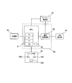
- FIG. 2 is a block diagram showing an electric circuit, which includes an LED illumination unit 1, an LED drive unit 2, a plurality of rechargeable lithium ion battery power supply units 3 connected in series or in parallel, and an MPU board, for example.
- the control unit 4 the switch unit 5 having three kinds of change-over switches 5B for adjusting the illumination intensity of the power on / off switch 5A and the LED illumination unit 1 to high, medium and low, and the battery power unit 3 It is comprised from the AC adapter as the charger 6 which charges.
- the LED driving unit 2, the control unit 4, and the switch unit 5 constitute a control unit 10 together.
- the LED illumination unit 1 and the battery power supply unit 3 are configured separately from the control unit 10 but are electrically connected during operation. Further, the charger 6 can be connected to the control unit 10 as necessary.
- the control unit 4 controls the light emission operation of the LED illumination unit 1 through the LED drive unit 2 when a power-on signal is input from the switch unit 5 by turning on the power on / off switch 5A.
- the control unit 4 drives the LED so that a constant current according to the designated light intensity is supplied to the LED illumination unit 1. Control part 2.
- FIG. 6 shows the configuration of the LED drive unit 2 that drives the LED illumination unit 1 with a constant current.
- an LED drive unit 2 includes an LED 29 of the LED illumination unit 1 and a drive transistor 23 connected on the collector side thereof, a resistor 24 connected to the emitter side of the transistor 23 and grounded at the other end, and an LED 22
- a constant voltage diode 25 connected to the power supply terminal 28 in parallel, a resistor 26 having one end connected to the constant voltage diode 25 and the other end grounded, and the middle point between the constant voltage diode 25 and the resistor 26 is the +
- the operational amplifier 27 is connected to the input side, the emitter side of the transistor 23 and the middle point of the resistor 24 are connected to the negative input side, and the output side is connected to the base side of the transistor 23.
- the other end of the LED 29 of the LED illumination unit 1 connected to the collector side of the transistor 23 is connected to a power supply terminal 28 to which the power of the battery power supply unit 3 is supplied.
- the transistor 23 when the control unit 4 supplies a voltage corresponding to a specified illumination intensity based on the operation of the changeover switch 5B to the power supply terminal 28, the transistor 23 is applied with a base voltage by the operational amplifier 27.
- the LED 29 is on and current flows through the LED 29.
- a current also flows through the path of the constant voltage diode 25 and the resistor 26, and the terminal voltage of the resistor 26 applied to the + input side of the operational amplifier 27 is constant.
- the operational amplifier 27 is configured to turn off the transistor 23. The voltage is controlled so that no current flows through the LED. Constant current operation can be performed by always repeating this.
- the light emitting operation of the LED illuminating unit 1 is not limited to the above-described constant current driving method, and the LED is controlled by controlling the duty ratio according to the illumination intensity specified by a switch device on the circuit, such as a transistor or MOSFET.
- a pulse driving method for controlling the current flowing to the illumination unit 1 may be used.
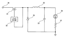
- FIG. 7 shows a configuration of the LED driving unit 2 by a pulse driving method.
- a MOSFET is used as the switch device 31 and connected to the gate side so that a PWM (Pulse Width Modulation) signal from the pulse generator 32 is input, and when the PWM signal becomes high level, the switch device 31 31 is turned on, and a current flows from the input side connected to the power supply terminal 36 to which the voltage of the battery power supply unit 3 is applied to the load side.
- PWM Pulse Width Modulation
- An LED 34 and a resistor 37 of the LED illuminating unit 1 are connected to the load side of the switch device 31 and grounded.
- a smoothing circuit including a coil, 32, and a capacitor 33 is provided in the preceding stage to provide a pulse by switching operation. The output is averaged and output.
- a diode 35 is provided in front of the coil 32 in order to keep supplying current to the coil 32 even when the switch device 31 is turned off. Thereby, if the ON time (OFF time) of the switch device 31 is controlled, the electric current which flows into the LED illumination part 1 can be adjusted efficiently. Therefore, in this case, the control unit 4 can adjust the brightness of the LED illumination unit 1 by performing control to change the duty ratio of the pulse generator 32.
- the control unit 4 checks the power supply capacity of the battery power supply unit 3. When a voltage drop is detected, the control unit 4 turns on the indicator 9 to give a warning, and when the charger 6 is connected to the control unit 10. Then, the battery power supply unit 3 is charged by controlling the current supply for charging the battery power supply unit 3 from the charger 6.
- LED light has a small amount of heat generation, and has an advantage that the irradiation object is not easily affected by heat even when irradiated for a long time. Therefore, in a medical operation for several hours, the human tissue is not damaged, and it is suitable as a light source device for medical operation.
- the LED illumination unit 1 is attached using the binocular loupe as a holder 7 in the example of FIG.
- the binocular loupe is widely used in various fields such as the medical field, precision work, and jewelry processing as a means of magnifying and visually recognizing a local visual object at hand.
- a binocular loupe main body 12 (primary mirror) for enlarging the image of the work object
- a main mirror attachment portion 13 for attaching the binocular loupe main body 12 to the main mirror attachment frame 11, and the visual acuity of the precision operator
- It comprises a focus adjustment unit 14 capable of compensation, a primary mirror mounting carrier lens 15 for mounting a binocular loupe body, and a frame vine portion 16 for mounting to a precision operator.
- the LED illumination unit 1 attaches the LED illumination unit 1 to the bridge 17 of the binocular loupe by the mounting means 18.
- the mounting means 18 includes a pair of opposing plates 52 that sandwich the binocular loupe bridge 17, screw holes 51 provided in the opposing plates 52, and screws 50.
- the screws 50 are also formed on the binocular loupe bridge 17.
- the LED illumination part 1 is attached to a binocular loupe by passing through the through hole and the screw hole 51 of the counter plate 52 and tightening.
- the energization cord 19 from the control unit 10 to the LED illuminating unit 1 is hung on the front of the operator's body by being held on the primary mirror mounting frame 11 and the frame vine portion 16 by an appropriate means (not shown). To prevent.
- the deep depth of focus required for the binocular loupe can be realized deeper.
- the holder 7 is not limited to such a binocular loupe, and may be a hat or a headband.
- FIG. 4 shows an example in which the headband is used as the holder 7, and the LED illumination unit 1 is attached to the headband.
- the headband is made of a resin member, and can be fixed by being held on the operator's head by its elasticity.
- the headband is not limited to such a configuration, and there are various forms of materials such as cloth and rubber.
- the headband illustrated in FIG. 4 is configured integrally with the LED illumination unit 1 and the headband.
- the mounting means 18 and the clip using the screw 50 shown in FIG. If the LED illuminating unit 1 is appropriately attached to and detached from the headband by a mounting means such as the above, various general-purpose headbands can be used as the holder 7.
- the LED illuminating unit 1 may be attached to the headband, but the LED illuminating unit 1 may be configured integrally with the headband. Moreover, although the electric cord from the LED illumination part 1 is connected to the control unit 10, it is good to connect it via the cord reel which winds a cord.
- FIG. 5 shows the battery holding belt 8 that holds the battery power supply unit 3 so that the operator can attach the battery power supply unit 3 to a part of the body.
- a plurality of battery power supply units 3 are connected to each other by a cord reel, and the battery power supply unit 3 and the control unit 10 are also connected.
- the battery power supply unit 3 and the control unit 10 are annularly arranged on the battery holding belt 8.
- the battery holding belt 8 holds a plurality of battery power supply units 3 in a state of being embedded in the belt.
- the operator can attach the battery power supply unit 3 and the control unit 10 to the body together with the LED illumination unit 1 during the operation by winding the battery holding belt 8 around the waist, and is arranged on the front surface of the control unit 10.
- the operation can be performed while operating the power ON / switch 5A and the changeover switch 5B that adjusts the illumination intensity in three ways: high, medium, and low.
- the charger 6 can always be connected to the control unit 10.
- the control unit 4 performs both the control of the LED lighting unit 1 and the charging control to the battery power source unit 3 at the same time, light is emitted from the LED lighting unit 1 while charging. It can handle work that takes time.
- the battery power supply unit 3 is attached to the operator's body with the battery holding belt, so that a large battery or a large number of batteries can be carried even in a small size in the medical field. Therefore, it is possible to secure a large power supply capacity sufficient to obtain a sufficient illumination time for performing the above procedure.
- FIG. 8 is a block diagram showing a circuit configuration of the medical light source device according to the second embodiment, an LED illumination unit 61 having an LED element, a control unit 54 including a microprocessor unit MPU and the current control circuit 2,
- the switch unit 55 includes a battery power source unit 60 formed by connecting a plurality of rechargeable batteries, and an AC adapter as a charger 56 that charges the battery power source unit 60.
- a processing procedure for controlling these peripheral devices is programmed in the microprocessor unit (hereinafter simply referred to as MPU) of the control unit 54.
- the switch unit 55 includes a first switch 55A for lighting the LED illumination unit 61 and second switches 55B and 55C for lighting the LED illumination unit 61 with an increased amount of light.
- the control unit 54 controls the current control circuit 62 so that the average current value flowing through the LED illumination unit 61 is increased from the rated value to an increased value larger than the rated value. .
- two switches 55B and 55C are provided so that the increasing light quantity can be selected in two ways, so that the operator can select the increasing light quantity appropriately large or small.
- control unit 54 checks the power supply capacity of the battery power supply unit 60. When the voltage drop is detected, the control unit 54 turns on the indicator 59 to give a warning, and when the charger 56 is connected to the control unit 54, the control unit 54 The unit 54 performs charging by controlling the current supply for charging the battery in the battery power supply unit 60 from the charger 6.
- FIG. 9 is a flowchart showing a processing procedure for controlling the lighting of the LED illumination unit 1 by the MPU of the control unit 4.
- the MPU starts the processing procedure when the switch 5A is operated, and controls the current control circuit 62 to supply the rated current to the LED illumination unit 1 (step S1).
- the current control circuit 62 is controlled by the MPU so that the average current value flowing from the battery power supply unit 60 to the LED illumination unit 61 becomes the rated value.
- step S2 the MPU confirms whether or not the timer T2 flag is set in the register R (step S2). If not set, the process proceeds to step S4. If set, the timer value is added to the timer T2 of the register R. The timer is counted (step S3). Although the processing of step S2 and step S3 will be apparent later, the timer flag T2 is not set here, and the MPU performs the processing of step S4.
- step S4 a signal from the switch unit 55 is acquired and the operation of the switch 55A is confirmed. If the switch 55A is not operated for the second time from the start, the operation of the switch 55B or the switch 55C is confirmed (step S5). When the operation of any one of the switches 55B and 55C is confirmed, the MPU confirms whether or not the timer T2 timed by the register R provided therein has expired (step S6). In this case, the timing operation by the timer T2 is not performed, and the process proceeds to the next step S7.
- step S7 the MPU sets the increased light quantity flag F0 in the register R, and the increased light quantity flag F0 is written with data for identifying the operated switch 55B or switch 55C.
- the MPU controls the current control circuit 62 to increase the illumination light amount of the LED illumination unit 61 according to the operated switch 55B or switch 55C based on the content of the increase light amount flag F0 (step S8).
- this light quantity increase control an average current value flowing through the LED illumination unit 61 is increased from a rated value to a current having an increased value larger than the rated value. Even if either of the switches 55B and 55C is operated, the supply current to the LED illumination unit 61 becomes an increased value exceeding the rated value. However, the current that flows when the switch 55B is operated is greater for the switch 55C. It is higher than the current that flows when operated.
- the MPU increases an increased value larger than the rated value in the LED illumination unit 61.
- the time during which the current is passed is set to a predetermined period based on the temperature rise characteristic of the LED element.
- the predetermined period is set so that the temperature of the LED element within the predetermined period does not exceed the maximum allowable value based on the temperature rise time characteristic of the LED element.
- the MPU adds the timer value to the timer T1 of the register R and measures the timer T1 (step S9). Then, as a result of the addition, it is determined whether the timer time has passed the predetermined period by determining whether the value of the timer T1 has reached a predetermined determination value (step S10). At this time, the predetermined period is set to be short so that a larger current flows when the switch 55B having a large increase light amount is operated, and the MPU responds to the content of the increase light amount flag F0 set in the register R.
- the timer T1 is programmed to change the judgment value.
- a timer time of 20 minutes is set as the predetermined period in order to increase the light amount by 40% compared to when the normal rated current is supplied, while the switch 55C is operated.
- the timer time of 30 minutes is set as the predetermined period in order to increase the amount of light of the LED illumination unit 61 by 30% compared to the time of normal rated current supply.
- step S10 When it is determined in step S10 that it is within the timer time, the MPU confirms that the switch 55A is not operated (step S13), and repeats the operation from step S8. That is, the MPU is in the increased light amount control mode.
- step S13 the current control circuit 62 is controlled to stop the supply of current to the LED illumination unit 61 and the LED illumination. The lighting of unit 1 is terminated (step S12). At the same time, all the contents of the register R are cleared and the initial state is entered.
- step S10 when the MPU confirms the end of the timer time T1 in step S10, the MPU sets the timer T2 flag F1 in the register R and clears the increased light quantity flag F0 (step S11).
- the supply current to the illumination unit 61 is switched to the rated value, the control of the increased light quantity is terminated, and the operation starts from step S2.
- the MPU has an increased value even if the switch 55B or the switch 55C is operated for a certain period after the light amount of the LED illumination unit 1 is increased and the current of the rated value is supplied again to return to the normal light amount. The flow of current is stopped. This fixed period is set to the time until the temperature of the LED element drops below the rated allowable value after an increased value of current is passed through the LED illumination unit 1.
- step S2 when the processing of step S2 is performed in a state where the light amount of the LED illumination unit 61 is increased and the current of the rated value is supplied again to return to the normal light amount, the MPU timers the register R in the processing of the previous step S11. Since the T2 flag F1 is set, the timer T2 is counted by adding the timer value to the timer T2 of the register R in the next step S3.
- the MPU controls the light emission with the normal light amount while measuring the timer T2, unless it is instructed to stop driving the LED illumination unit 61 by operating the switch 5A in step S4.
- step S6 it is determined whether the value of the timer T2 has reached a predetermined determination value. Determine if the period has elapsed.
- the predetermined period at this time is the above-described time from when an increased value of current is passed through the LED illumination unit 61 until the temperature of the LED element falls below the rated allowable value.
- step S7 the increased light amount flag F0 is set in the register R, and the increased light amount control is performed.
- step S2 the processing from step S2 is performed without performing the increase light amount control, and the timer T2 is measured while controlling the light emission with the normal light amount.
- the LED illumination unit 61 prevents deterioration of the LED element due to heat generation.
- a high luminous flux (brightening) is realized by supplying an increased current exceeding the rated current within the guaranteed timer time.
- FIG. 10 is a block diagram showing an electric circuit of the medical light source device according to the third embodiment of the present invention. Components having the same functions as those in FIG. Description is omitted.
- a temperature sensor 63 using a thermistor or the like is provided for the temperature of the LED element of the LED illumination unit 61.
- the processing procedure for controlling the lighting of the LED illumination unit 61 by the MPU is also different from the processing procedure of FIG. 9, and will be described below.
- the MPU starts the processing procedure when the switch 55A is operated, and controls the current control circuit 62 to supply the rated current to the LED illumination unit 61 (step S21).
- the current control circuit 62 is controlled by the MPU so that the average current value flowing from the battery power supply unit 60 to the LED illumination unit 61 becomes a rated value.
- the MPU acquires a signal from the switch unit 55 and confirms the operation of the switch 55A (step S22), and if not operated, confirms the operation of the switch 55B or the switch 55C (step S23). If the switch 55B or the switch 55C is not operated, the processing from step S22 is repeated. However, if the operation of the switch 55A is confirmed in step S22, the processing is step S29, and the MPU supplies the battery power supply unit to the LED illumination unit 61. The light emission operation is stopped by controlling the current control circuit 62 so as to stop the current supply from 60.
- the MPU captures the output from the temperature sensor 54 to detect the temperature (step S24), and the detected temperature is a predetermined temperature (for example, 80 ° C. or If the temperature is equal to or lower than the predetermined temperature, the switch 55B operated in the register R or the increased light amount flag F0 corresponding to the switch 55C is set (step S26). ).
- the increased light quantity flag F0 is data for identifying the operated switch 5B or switch 55C.
- the MPU performs the increased light amount control according to the content of the increased light amount flag F0 (step S27), confirms whether or not the stop of the light emission is instructed by the operation of the switch 55A in the next step S28, and the switch If 55A is not operated, the process returns to step S22.
- the MPU performs current control so that the illumination light amount of the LED illumination unit 61 is increased according to the operated switch 55B or switch 55C based on the content of the increased light amount flag F0 as in the processing procedure of FIG.
- the circuit 62 is controlled.
- step S25 when it is detected in step S25 that the temperature detected by the temperature sensor 63 has reached the predetermined temperature while the illumination light amount of the LED illumination unit 61 is increasing, the increased light amount of the register R is detected.
- the flag F0 is cleared and the process of step S21 is performed, and the MPU switches the current supplied to the LED illumination unit 61 to the rated value, ends the light quantity increase control, and the process from step S22.
- the current control circuit 62 is controlled to stop the supply of current to the LED illumination unit 61 (step S29).
- the contents of the register R are cleared and the initial state is entered.
- the MPU controls the current control circuit 62 so as to supply the rated current to the LED illumination unit 61, and the LED illumination unit 61 emits light with a normal light amount. If it is confirmed that the switch 55B or the switch 55C is operated without operating the switch 55A, the MPU performs the process of step S24, detects the temperature by taking the output from the temperature sensor 54, and the detected temperature is predetermined. It is determined whether or not the temperature is exceeded (step S25). If the temperature is lower, the switch 55B operated in the register R or the increased light amount flag F0 corresponding to the switch 55C is set in the register R (step S26), and the increased light amount control is performed again. repeat. Therefore, while confirming that the temperature of the LED element is lower than the predetermined value in step S25, the light quantity increase can be resumed even after the light increase is completed.
- FIGS. 8 and 10 a specific circuit configuration of the current control circuit 62 in FIGS. 8 and 10 will be described, and control of the supply current to the LED illumination unit 61 by the MPU in the control unit 54 will be described. Note that two configurations of the current control circuit 62 are illustrated in FIGS. 12 and 13, but any of the current control circuits 62 in FIGS. 12 and 13 may be used.
- the current control circuit 62 shown in FIG. 12 connects the power source Vcc to the LED element 65 of the LED illumination unit 61, the drive transistor Q1 connected on the collector side, and the resistance circuit 66 connected to the emitter side of the transistor Q1. It consists of Then, the MPU connects the base of the transistor Q1 at the port a through the resistor R11 and controls the ON / OFF thereof.
- the resistor circuit 66 includes a resistor R1 connected at one end to the emitter of the transistor Q1 and grounded at the other end, a series circuit of a transistor Q2 and a resistor R2 connected in parallel to the resistor R1, and also connected in parallel to the resistor R1. And a series circuit of a transistor Q3 and a resistor R3.
- the base of the transistor Q2 is connected to the port b of the MPU of the control unit 54 through the resistor R12, and the base of the transistor Q3 is connected to the port c of the control unit 4 through the resistor R13.
- the resistor R11, the resistor R12, and the resistor R13 are provided to limit the base current to each connected transistor.
- the resistance value of the resistance circuit 12 is determined by the combined resistance value of the resistors R1, R2, and R3. In a normal state where the transistor Q2 and the transistor Q3 are OFF, the current limiting resistance value is R1, the transistor Q2 is ON, and the transistor Q3 is OFF Is R1 ⁇ R2 / (R1 + R2), and when both the transistor Q2 and the transistor Q3 are ON, R1 ⁇ R2 ⁇ R3 / (R1 + R2 + R3).
- the resistance values of the resistors R1, R2, and R3 are set so that R1> R1 ⁇ R2 / (R1 + R2)> R1 ⁇ R2 ⁇ R3 / (R1 + R2 + R3).
- the LED element 65 is set. Is the rated value, the supply current when the current limiting resistance value is R1 ⁇ R2 / (R1 + R2) is an increased value, and the current supply when the current limiting resistance value is R1 ⁇ R2 ⁇ R3 / (R1 + R2 + R3) is further Try to increase.
- the control unit 54 turns off both the transistor Q2 and the transistor Q3, the LED element 65 is supplied with a rated current and has a normal light emission amount, but when the transistor Q2 is turned on, the increased value is obtained.
- the transistor Q2 and the transistor Q3 are both turned on, the supply current further increases and the amount of light emission increases.
- control for turning off the transistor Q2 and the transistor Q3 by the control unit 54 corresponds to the processing of “supplying the rated current to the LED” in the processing procedure described above, and the control for turning on the transistor Q2 is performed when the switch 5B is operated.
- the control for turning on both the transistor Q2 and the transistor Q3 corresponds to “light quantity increase control” when the switch 5C is operated.
- the current control circuit 62 having such a configuration, when the MPU turns on the transistor Q 1 and supplies the power supply Vcc to the current control circuit 2, a current flows through the LED element 29. At this time, since the control unit 54 turns off the transistors Q2 and Q3, the rated current flows through the LED element 29 to perform normal light emission.
- the MPU controls the ON / OFF of the transistor Q1 with a predetermined duty ratio so that a predetermined current flows. Therefore, the voltage applied to the LED element 29 has a rectangular wave shape. However, the voltage is not limited to the rectangular wave, and it is preferable to make the rising and falling steps into a step shape. Thereby, a rapid change in illuminance can be eliminated.
- the MPU When the MPU turns on the transistor Q2 or turns on both the transistor Q2 and the transistor Q3 by operating the switch 55B or the switch 55C, a current corresponding to the current limiting resistance value of the resistor circuit 66 flows to the LED element 65 to emit light. To do. Therefore, when the switch 55B or the switch 55C is operated during the illumination operation of the LED illumination unit 61 with the rated current, the MPU causes an amount of current exceeding the rated current to be applied to the LED element 65 in accordance with the increased light amount of the operated switch. The LED illumination unit 61 is controlled to flow. In this way, the control unit 54 switches the light emission amount of the LED element 29 by controlling the transistors Q1, Q2, and Q3 from the ports a, b, and c of the MPU.
- the light emitting operation of the LED lighting unit 61 is not limited to the circuit configuration described above, and the LED lighting unit is controlled by controlling the duty ratio according to the designation of the lighting intensity with a switch device on the circuit, such as a transistor or a MOSFET.
- a pulse driving method for controlling the current flowing to 1 may be used.
- FIG. 13 shows the configuration of the current control circuit 62 by the pulse drive method.
- a MOSFET is used for the switch device 71, and a PWM (PulseulWidth Modulation) signal from the pulse generator 72 is connected to the gate side of the switch device 71, and the port a ′ of the MPU of the control unit 4 is connected.
- PWM PulseulWidth Modulation
- An LED 74 of the LED illumination unit 61 and a protective resistor R4 are connected to the load side of the switch device 71 and grounded, but a smoothing circuit including a coil, L, and a capacitor C is provided in the preceding stage to perform switching operation.
- the pulse output is averaged and output.
- a diode 75 is provided in front of the coil L to keep supplying current to the coil L even when the switch device 71 is turned off. Thereby, if the ON time (OFF time) of the switch device 71 is controlled, the electric current which flows into the LED illumination part 61 can be adjusted. Therefore, in this case, the control unit 54 can increase the amount of light of the LED illumination unit 61 by performing control to change the duty ratio of the pulse generator 72.
- the voltage applied to the LED element 34 has a rectangular wave shape, but is not limited to a rectangular wave, and may have a substantially half-wave shape by making its rise and fall stepwise.
- the MPU performs control to change the duty ratio so that the average current value flowing through the LED illumination unit 61 flows from the rated value to an increased current larger than the rated value. Even if either of the switches 55B and 55C is operated, the supply current to the LED illumination unit 61 becomes an increased value exceeding the rated value. However, the current that flows when the switch 55B is operated is greater for the switch 55C. It is higher than the current that flows when operated.
- the control in which the MPU outputs a control signal from the port a ′ to the pulse generator 32 corresponds to the processing of “supplying rated current to the LED” in the processing procedure and “increasing light quantity control” when the switch 5B or the switch 5C is operated. To do.
- the control signal output from the port a ′ by the MPU indicates a duty ratio for supplying the rated current to the LED illumination unit 61.
- the MPU outputs a control signal for changing the duty ratio so as to supply an increased current according to the increased light amount of the operated switch.
- the above-described medical light source device is a light source device using an LED element that can be worn on an operator's body.
- a current that is equal to or less than the maximum value and exceeds the rated value (continuous rated value) over a predetermined period in a range that does not deteriorate, the amount of light can be increased without using a complicated configuration. Therefore, the power consumption is not consumed more than necessary, and a long illumination time necessary for use in the operation at the medical site can be secured.
- LED lighting devices used for lighting applications in the home, etc. dimming the amount of light emitted from the LED in multiple stages, both of which continuously emit light with the adjusted amount of light emitted.
- the light emission state is adjusted to a high output, it is assumed that heat is generated accordingly, and it is necessary to take appropriate heat dissipation measures in preparation for an extreme decrease in life due to a sudden stop or deterioration due to heat.
- a heat dissipation measure leads to an increase in the size of the medical light source device that is supposed to be downsized so that it can be mounted on the operator's body.
- the LED illumination unit 61 is attached to the operator's body by a holder, but is held by, for example, a binocular loupe and attached to the operator's head. Further, the battery power supply unit 60 may be mounted on a part of the operator's body as in the first embodiment. In this case, if the battery holding belt 8 shown in FIG. 5 is attached to the operator's waist, the control unit 54 including the MPU and the current control circuit 62 and the switch unit 55 are controlled together with the battery power source unit 60.
- the unit 10 is integrated and attached to the battery holding belt 8, and the control unit 10 is configured to supply a drive current to the LED illumination unit 61 through the cord 42 to control the illumination operation.
- the control unit 10 controls the charging of the battery power supply unit 3 when the charger 6 with the plug inserted into the outlet 41 is connected. The lighting operation by the LED lighting unit 1 while charging the battery power supply unit 3 is performed. It can be performed.
- the movement of the operator is detected by an acceleration sensor, and the amount of light emission is controlled according to the movement.
- the time required to irradiate a local area with a larger amount of light for example, by performing resection or suturing of a blood vessel or a minute portion, is about 20% of the total. Therefore, power consumption can be suppressed by controlling the LED illumination unit 1 to be dark except for the time of about 20%.
- FIG. 14 is a block diagram showing the configuration of this electric circuit.
- the LED illumination unit 81, the LED drive unit 82, the battery power supply unit 83, the control unit 84, the power on / off switch 85A, and the LED illumination unit 81 are shown. It comprises a switch unit 85 having three kinds of change-over switches 85B for adjusting the illumination intensity to high, medium and low, an AC adapter as a charger 86 for charging the battery power supply unit 83, and an acceleration sensor 80.
- the acceleration sensor 80 can be used in various types, such as a mechanical type, an optical type, and a semiconductor type.
- a semiconductor type is optimal as a medical light source device in terms of miniaturization. This is especially true when the holder is a binocular loupe, hat or headband that can be worn on the operator's head.
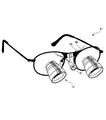
- FIG. 15 shows an example in which the acceleration sensor 80 is mounted on the binocular loupe 87.
- the acceleration sensor 80 detects vibration caused by the movement of the operator's head and converts it into an electrical signal. To transmit.
- the acceleration sensor 80 is attached to the binocular loupe 87 with an adhesive tape or the like.
- the control unit 84 controls the light emitting operation of the LED illumination unit 81 through the LED driving unit 82.
- the control unit 84 drives the LED so that a constant current according to the designated light intensity at this time is supplied to the LED illumination unit 81.
- the unit 82 is controlled.
- the control unit 84 controls the LED driving unit 82 so as to decrease the illuminance of the LED lighting unit 81 when the acceleration sensor 80 detects an acceleration equal to or higher than a predetermined value when the LED lighting unit 81 is energized. When the acceleration falls below a predetermined value, the control unit 84 controls the LED drive unit 82 to emit light with the light intensity specified by the changeover switch 85B.
- the operator holds the LED illumination unit 81 together with the LED illumination unit 81 in order to concentrate the light on the operation target site.
- the acceleration detected by the acceleration sensor 80 held by the tool is small, and the control unit 84 emits light with the intensity required by the operator.
- the operator makes a large movement that moves the entire body during preparation work, etc., so the head vibrates and is detected by the acceleration sensor 80. The acceleration that is performed is increased.
- the control unit 84 controls the LED driving unit 82 so as to decrease the illuminance of the LED illumination unit 81, thereby effectively using the battery power supply unit 83. At this time, when the acceleration detected by the acceleration sensor 80 becomes a predetermined value or more, the illumination of the LED illumination unit 81 may be stopped.
- the battery power supply unit 83 may be mounted on a part of the operator's body as in the first embodiment. In this case, if the battery holding belt 8 shown in FIG. 5 is attached to the operator's waist, the control unit 84 and the switch unit 85 are integrated with the control unit 10 together with the battery power supply unit 83, and the battery holding belt. Attach to 8.
- the control of the illuminance of the LED illumination unit 81 using such an acceleration sensor can also be applied to the configurations of the second and third embodiments described above.
- an average current value flowing through the LED illumination unit 61 (FIG. 8 or FIG. 10) is passed through an increased current larger than the rated value, and high output light emission control is started.
- the MPU periodically monitors the acceleration detection signal from the acceleration sensor by a timer interrupt, and controls the average current value flowing through the LED illumination unit 61 to the rated value when the acceleration exceeds a predetermined value.
- the present invention secures a large-capacity battery power source by attaching a battery to the body, makes a LED element emit light at a high output for a certain time by operating a switch, and includes an acceleration sensor.
- the illuminance is reduced during a period in which it is determined that irradiation of intense light is not necessary from the movement of the operator, thereby enabling long-time illumination in the medical light source device.
- the illumination time can be extended, but as described above, the illumination can be performed for a longer time by adopting a combination as appropriate.
- the medical light source device can be used while being connected to an AC commercial power source.
- the LED is driven by a 12V DC power source obtained by converting the commercial power source AC100V into a direct current.
- the full-wave rectifier circuit 101 is connected to the commercial power source via the transformer 100.
- a configuration in which full-wave rectification is smoothed by a smoothing circuit 102 and converted into a direct current is supplied to the LED drive circuit 103.
- the battery power supply B is connected to the smoothing circuit 102 through a diode D for preventing backflow. Therefore, the power supply to the LED drive circuit 103 is automatically switched from the battery power supply B to the power failure or when the AC power cord is disconnected and the power supply is stopped. The LED is continuously illuminated.
- FIG. 17 shows a configuration of an LED illumination unit 91 incorporating a small fan
- the LED illumination unit 91 houses an LED unit 93 in a cylindrical casing 92.
- the LED unit 93 has a substrate 94 on which LED elements are mounted, and is fixed in the housing 92 by attaching the substrate 94 to the housing 92 on the inner wall.
- the light emitted from the LED element is projected to the outside through a lens 94 that forms a cap portion of the housing 92.
- a recess 95 is formed on a part of the side surface of the housing 92 so that, for example, the small fan 96 having the above-described dimensions can be accommodated.
- This small fan 96 is an axial flow type fan, and air flows between the suction port 97 provided on the bottom surface of the recess 95 and the exhaust port 98 provided on the side surface of the housing 92 so as to face the suction port 97.
- the LED unit 93 is formed and cooled.
- the small fan 96 is supplied with power via a lead wire 99 from a battery power source for supplying power to the LED illumination unit 91.
Priority Applications (10)
| Application Number | Priority Date | Filing Date | Title |
|---|---|---|---|
| KR1020127017407A KR101222551B1 (ko) | 2010-11-17 | 2011-05-24 | 의료용 광원장치 |
| EP11842075.1A EP2527716A4 (en) | 2010-11-17 | 2011-05-24 | MEDICAL LIGHT SOURCE DEVICE |
| BR112012018425A BR112012018425A2 (pt) | 2010-11-17 | 2011-05-24 | dispositivo médico de fonte de luz. |
| US13/520,065 US8920013B2 (en) | 2010-11-17 | 2011-05-24 | Medical light-source device |
| MX2012010613A MX2012010613A (es) | 2010-11-17 | 2011-05-24 | Dispositivo de fuente de luz medico. |
| JP2011544751A JP4937423B1 (ja) | 2010-11-17 | 2011-05-24 | 医療用光源装置 |
| RU2012136938/07A RU2012136938A (ru) | 2010-11-17 | 2011-05-24 | Медицинское светоизлучающее устройство |
| CN201180010367.6A CN102762914B (zh) | 2010-11-17 | 2011-05-24 | 医疗用光源装置 |
| CA2791276A CA2791276A1 (en) | 2010-11-17 | 2011-05-24 | Medical light-source device |
| US14/502,265 US9532846B2 (en) | 2010-11-17 | 2014-09-30 | Medical light-source device |
Applications Claiming Priority (4)
| Application Number | Priority Date | Filing Date | Title |
|---|---|---|---|
| JP2010007565U JP3165663U (ja) | 2010-11-17 | 2010-11-17 | 医療用光源装置 |
| JP2010-007565U | 2010-11-17 | ||
| JP2011004941A JP4841013B1 (ja) | 2011-01-13 | 2011-01-13 | 医療用光源装置 |
| JP2011-004941 | 2011-01-13 |
Related Child Applications (2)
| Application Number | Title | Priority Date | Filing Date |
|---|---|---|---|
| US13/520,065 A-371-Of-International US8920013B2 (en) | 2010-11-17 | 2011-05-24 | Medical light-source device |
| US14/502,265 Continuation US9532846B2 (en) | 2010-11-17 | 2014-09-30 | Medical light-source device |
Publications (1)
| Publication Number | Publication Date |
|---|---|
| WO2012066808A1 true WO2012066808A1 (ja) | 2012-05-24 |
Family
ID=46083753
Family Applications (1)
| Application Number | Title | Priority Date | Filing Date |
|---|---|---|---|
| PCT/JP2011/061884 WO2012066808A1 (ja) | 2010-11-17 | 2011-05-24 | 医療用光源装置 |
Country Status (11)
| Country | Link |
|---|---|
| US (2) | US8920013B2 (zh) |
| EP (2) | EP2527716A4 (zh) |
| JP (1) | JP4937423B1 (zh) |
| KR (1) | KR101222551B1 (zh) |
| CN (1) | CN102762914B (zh) |
| AU (1) | AU2011330546A1 (zh) |
| BR (1) | BR112012018425A2 (zh) |
| CA (1) | CA2791276A1 (zh) |
| MX (1) | MX2012010613A (zh) |
| RU (1) | RU2012136938A (zh) |
| WO (1) | WO2012066808A1 (zh) |
Families Citing this family (25)
| Publication number | Priority date | Publication date | Assignee | Title |
|---|---|---|---|---|
| US20120105740A1 (en) | 2000-06-02 | 2012-05-03 | Oakley, Inc. | Eyewear with detachable adjustable electronics module |
| US8482488B2 (en) | 2004-12-22 | 2013-07-09 | Oakley, Inc. | Data input management system for wearable electronically enabled interface |
| US7013009B2 (en) | 2001-06-21 | 2006-03-14 | Oakley, Inc. | Eyeglasses with wireless communication features |
| EP2095178B1 (en) | 2006-12-14 | 2015-08-12 | Oakley, Inc. | Wearable high resolution audio visual interface |
| ES2860692T3 (es) | 2009-06-09 | 2021-10-05 | Kerr Corp | Montaje de iluminación llevable por usuario |
| JP4841013B1 (ja) * | 2011-01-13 | 2011-12-21 | 正一 中村 | 医療用光源装置 |
| RU2012136938A (ru) * | 2010-11-17 | 2014-12-27 | Соити НАКАМУРА | Медицинское светоизлучающее устройство |
| US20120327643A1 (en) * | 2011-06-22 | 2012-12-27 | Nguyen Ronald C | Hands-free lighting system |
| CN205177388U (zh) | 2013-03-15 | 2016-04-20 | 奥克利有限公司 | 目镜系统 |
| CN205691887U (zh) | 2013-06-12 | 2016-11-16 | 奥克利有限公司 | 模块化通信系统和眼镜通信系统 |
| CN105451635B (zh) * | 2013-08-23 | 2017-08-11 | 奥林巴斯株式会社 | 光源装置和内窥镜装置 |
| JP6378901B2 (ja) * | 2014-03-06 | 2018-08-22 | オリンパス株式会社 | 光源装置、内視鏡装置及び光源制御方法 |
| WO2016142262A1 (en) * | 2015-03-06 | 2016-09-15 | Forstgarten International Holding Gmbh | Removably attachable device or device holder |
| CN104665754A (zh) * | 2015-03-11 | 2015-06-03 | 杭州创辉医疗电子设备有限公司 | 无线宫腔镜 |
| GB2536650A (en) | 2015-03-24 | 2016-09-28 | Augmedics Ltd | Method and system for combining video-based and optic-based augmented reality in a near eye display |
| CN104849847B (zh) * | 2015-05-19 | 2017-08-01 | 梧州学院 | 一种袖珍式暗场宝石显微镜 |
| JP6294898B2 (ja) * | 2016-01-15 | 2018-03-14 | Hoya Candeo Optronics株式会社 | 光照射装置 |
| WO2017171175A1 (ko) * | 2016-03-29 | 2017-10-05 | 주식회사 더블에이치 | Led들을 이용하여 체지방을 감소시키는 웨어러블 장치와 이의 동작 방법 |
| CA3036209A1 (en) * | 2016-09-16 | 2018-03-22 | Invuity, Inc. | Methods and apparatus for electrosurgical illumination |
| KR102032126B1 (ko) | 2018-01-31 | 2019-10-15 | 광주대학교 산학협력단 | 유기발광다이오드를 이용한 의료용 조명장치 |
| WO2019211741A1 (en) | 2018-05-02 | 2019-11-07 | Augmedics Ltd. | Registration of a fiducial marker for an augmented reality system |
| US11766296B2 (en) | 2018-11-26 | 2023-09-26 | Augmedics Ltd. | Tracking system for image-guided surgery |
| US20210149222A1 (en) * | 2019-11-14 | 2021-05-20 | Jay Emirzian | Dental Shade-Matching Device |
| US11382712B2 (en) | 2019-12-22 | 2022-07-12 | Augmedics Ltd. | Mirroring in image guided surgery |
| US11896445B2 (en) | 2021-07-07 | 2024-02-13 | Augmedics Ltd. | Iliac pin and adapter |
Citations (7)
| Publication number | Priority date | Publication date | Assignee | Title |
|---|---|---|---|---|
| JPH0323009U (zh) * | 1989-07-17 | 1991-03-11 | ||
| JP2002163901A (ja) * | 2000-11-22 | 2002-06-07 | Osada Res Inst Ltd | 無影灯 |
| JP2006107846A (ja) * | 2004-10-01 | 2006-04-20 | Seventh Dimension Design:Kk | 頭部装着用照明器具 |
| JP2006185755A (ja) | 2004-12-28 | 2006-07-13 | Pentel Corp | クリップ型ledライト |
| JP2008210547A (ja) | 2007-02-23 | 2008-09-11 | Koudou:Kk | 照明装置及びこれを用いた帽子 |
| JP2009293146A (ja) | 2008-06-04 | 2009-12-17 | Tsurioh:Kk | ライト付帽子 |
| WO2010007785A1 (ja) * | 2008-07-15 | 2010-01-21 | 合同会社ジャパン・メディカル・クリエーティブ | 照明装置 |
Family Cites Families (12)
| Publication number | Priority date | Publication date | Assignee | Title |
|---|---|---|---|---|
| CN2036613U (zh) * | 1988-06-30 | 1989-04-26 | 任传俊 | 眼镜式灯具 |
| JP3023009U (ja) | 1995-09-22 | 1996-04-12 | 永島医科器械株式会社 | 額帯電灯 |
| JP2001338501A (ja) * | 2000-05-30 | 2001-12-07 | Takeshi Nakamura | ヘッドランプ |
| JP4142327B2 (ja) * | 2001-10-15 | 2008-09-03 | Hoya株式会社 | 双眼光学装置 |
| US8789962B2 (en) * | 2005-10-27 | 2014-07-29 | Vikon Surgical, Llc | Surgical headlight |
| GB0606940D0 (en) * | 2006-04-06 | 2006-05-17 | Optilume Ltd | Lighting device |
| US7824052B1 (en) * | 2007-03-16 | 2010-11-02 | Halm Gary V | Foot controlled light operation |
| CN201237142Y (zh) * | 2008-07-29 | 2009-05-13 | 一品光学工业股份有限公司 | 相机用的阵列式发光二极管闪光灯 |
| US20100280328A1 (en) * | 2009-05-01 | 2010-11-04 | Tyco Healthcare Group, Lp | Methods and systems for illumination during phlebectomy procedures |
| CN201487781U (zh) * | 2009-05-13 | 2010-05-26 | 台州真达灯饰有限公司 | 可多种供电方式的节日彩灯 |
| US8900138B2 (en) * | 2009-11-05 | 2014-12-02 | James P. Horvath | Headlight apparatus and method |
| RU2012136938A (ru) * | 2010-11-17 | 2014-12-27 | Соити НАКАМУРА | Медицинское светоизлучающее устройство |
-
2011
- 2011-05-24 RU RU2012136938/07A patent/RU2012136938A/ru not_active Application Discontinuation
- 2011-05-24 MX MX2012010613A patent/MX2012010613A/es active IP Right Grant
- 2011-05-24 KR KR1020127017407A patent/KR101222551B1/ko not_active IP Right Cessation
- 2011-05-24 US US13/520,065 patent/US8920013B2/en not_active Expired - Fee Related
- 2011-05-24 CA CA2791276A patent/CA2791276A1/en not_active Abandoned
- 2011-05-24 AU AU2011330546A patent/AU2011330546A1/en not_active Abandoned
- 2011-05-24 EP EP11842075.1A patent/EP2527716A4/en not_active Withdrawn
- 2011-05-24 CN CN201180010367.6A patent/CN102762914B/zh not_active Expired - Fee Related
- 2011-05-24 JP JP2011544751A patent/JP4937423B1/ja not_active Expired - Fee Related
- 2011-05-24 WO PCT/JP2011/061884 patent/WO2012066808A1/ja active Application Filing
- 2011-05-24 EP EP14192752.5A patent/EP2843293A2/en not_active Withdrawn
- 2011-05-24 BR BR112012018425A patent/BR112012018425A2/pt not_active IP Right Cessation
-
2014
- 2014-09-30 US US14/502,265 patent/US9532846B2/en not_active Expired - Fee Related
Patent Citations (7)
| Publication number | Priority date | Publication date | Assignee | Title |
|---|---|---|---|---|
| JPH0323009U (zh) * | 1989-07-17 | 1991-03-11 | ||
| JP2002163901A (ja) * | 2000-11-22 | 2002-06-07 | Osada Res Inst Ltd | 無影灯 |
| JP2006107846A (ja) * | 2004-10-01 | 2006-04-20 | Seventh Dimension Design:Kk | 頭部装着用照明器具 |
| JP2006185755A (ja) | 2004-12-28 | 2006-07-13 | Pentel Corp | クリップ型ledライト |
| JP2008210547A (ja) | 2007-02-23 | 2008-09-11 | Koudou:Kk | 照明装置及びこれを用いた帽子 |
| JP2009293146A (ja) | 2008-06-04 | 2009-12-17 | Tsurioh:Kk | ライト付帽子 |
| WO2010007785A1 (ja) * | 2008-07-15 | 2010-01-21 | 合同会社ジャパン・メディカル・クリエーティブ | 照明装置 |
Non-Patent Citations (1)
| Title |
|---|
| See also references of EP2527716A4 |
Also Published As
| Publication number | Publication date |
|---|---|
| EP2527716A1 (en) | 2012-11-28 |
| US20150015161A1 (en) | 2015-01-15 |
| MX2012010613A (es) | 2012-11-30 |
| EP2843293A2 (en) | 2015-03-04 |
| RU2012136938A (ru) | 2014-12-27 |
| BR112012018425A2 (pt) | 2019-09-24 |
| AU2011330546A1 (en) | 2012-07-26 |
| US20120281390A1 (en) | 2012-11-08 |
| US9532846B2 (en) | 2017-01-03 |
| US8920013B2 (en) | 2014-12-30 |
| CN102762914A (zh) | 2012-10-31 |
| KR20120096560A (ko) | 2012-08-30 |
| JP4937423B1 (ja) | 2012-05-23 |
| KR101222551B1 (ko) | 2013-01-16 |
| JPWO2012066808A1 (ja) | 2014-05-12 |
| CN102762914B (zh) | 2016-03-16 |
| CA2791276A1 (en) | 2012-05-24 |
| EP2527716A4 (en) | 2014-01-01 |
Similar Documents
| Publication | Publication Date | Title |
|---|---|---|
| JP4937423B1 (ja) | 医療用光源装置 | |
| JP5529978B2 (ja) | 医療用光源装置 | |
| JP5627795B2 (ja) | 装着型ヘッドライトデバイスおよび関連の方法 | |
| JP5530029B2 (ja) | 医療用光源装置 | |
| EP1772664A2 (en) | Flashlight | |
| WO2019143668A1 (en) | Physical assessment device | |
| JP3165663U (ja) | 医療用光源装置 | |
| JP6399423B2 (ja) | 点灯装置、及びそれに用いる光源ユニット、並びに照明器具 | |
| JP2022102551A (ja) | 充電器 | |
| JP2008149049A (ja) | 携帯内視鏡の光源駆動装置 | |
| JP5737766B2 (ja) | 携帯用電源装置 | |
| JP2001212080A (ja) | 内視鏡装置 |
Legal Events
| Date | Code | Title | Description |
|---|---|---|---|
| WWE | Wipo information: entry into national phase |
Ref document number: 201180010367.6 Country of ref document: CN |
|
| WWE | Wipo information: entry into national phase |
Ref document number: 2011544751 Country of ref document: JP |
|
| WWE | Wipo information: entry into national phase |
Ref document number: 13520065 Country of ref document: US Ref document number: 2011330546 Country of ref document: AU |
|
| ENP | Entry into the national phase |
Ref document number: 20127017407 Country of ref document: KR Kind code of ref document: A |
|
| 121 | Ep: the epo has been informed by wipo that ep was designated in this application |
Ref document number: 11842075 Country of ref document: EP Kind code of ref document: A1 |
|
| ENP | Entry into the national phase |
Ref document number: 2011330546 Country of ref document: AU Date of ref document: 20110524 Kind code of ref document: A |
|
| WWE | Wipo information: entry into national phase |
Ref document number: 2011842075 Country of ref document: EP |
|
| WWE | Wipo information: entry into national phase |
Ref document number: 7423/DELNP/2012 Country of ref document: IN |
|
| ENP | Entry into the national phase |
Ref document number: 2791276 Country of ref document: CA |
|
| WWE | Wipo information: entry into national phase |
Ref document number: MX/A/2012/010613 Country of ref document: MX |
|
| REG | Reference to national code |
Ref country code: BR Ref legal event code: B01A Ref document number: 112012018425 Country of ref document: BR |
|
| NENP | Non-entry into the national phase |
Ref country code: DE |
|
| ENP | Entry into the national phase |
Ref document number: 2012136938 Country of ref document: RU Kind code of ref document: A |
|
| ENP | Entry into the national phase |
Ref document number: 112012018425 Country of ref document: BR Kind code of ref document: A2 Effective date: 20120724 |