WO2012066643A1 - 蓄電デバイスの状態検知方法及びその装置 - Google Patents
蓄電デバイスの状態検知方法及びその装置 Download PDFInfo
- Publication number
- WO2012066643A1 WO2012066643A1 PCT/JP2010/070408 JP2010070408W WO2012066643A1 WO 2012066643 A1 WO2012066643 A1 WO 2012066643A1 JP 2010070408 W JP2010070408 W JP 2010070408W WO 2012066643 A1 WO2012066643 A1 WO 2012066643A1
- Authority
- WO
- WIPO (PCT)
- Prior art keywords
- voltage
- storage device
- open
- state detection
- state
- Prior art date
- Legal status (The legal status is an assumption and is not a legal conclusion. Google has not performed a legal analysis and makes no representation as to the accuracy of the status listed.)
- Ceased
Links
Images





Classifications
-
- G—PHYSICS
- G01—MEASURING; TESTING
- G01R—MEASURING ELECTRIC VARIABLES; MEASURING MAGNETIC VARIABLES
- G01R31/00—Arrangements for testing electric properties; Arrangements for locating electric faults; Arrangements for electrical testing characterised by what is being tested not provided for elsewhere
- G01R31/36—Arrangements for testing, measuring or monitoring the electrical condition of accumulators or electric batteries, e.g. capacity or state of charge [SoC]
- G01R31/382—Arrangements for monitoring battery or accumulator variables, e.g. SoC
- G01R31/3835—Arrangements for monitoring battery or accumulator variables, e.g. SoC involving only voltage measurements
Definitions
- the present invention relates to a power storage device state detection method and apparatus, and more particularly to a power storage device state detection method and apparatus for accurately detecting a state quantity based on an open-ended voltage after charging and discharging of a power storage device is stopped. It is.
- power storage devices are used for leveling generated power and storing surplus power when using natural energy such as solar power generation and wind power generation. Furthermore, the power storage device is also used as a backup power source such as a stabilized power source and an auxiliary power source for supplying power to an electric device during a power failure.
- a device that accompanies the movement of ions in an electrolyte such as a secondary battery or a capacitor or in a solid electrolyte is used.
- Patent Document 2 discloses a method of measuring the open-circuit voltage during relaxation after stopping charging and discharging, and performing state detection based on this.
- Patent Document 2 a differential voltage from a reference OCV (a stable OCV) of the measured open-end voltage is fitted with a predetermined function, and this is subjected to component decomposition (F_fast, F_slow) in accordance with the relaxation rate, A state detection method for obtaining SOC and SOH using reference data is described.
- component decomposition according to the relaxation rate it is possible to calculate the amount of change in the state amount by evaluating the influence on the state amount for each characteristic having a different relaxation rate. That is, in the state detection method of Patent Document 2, the change in OCV is regarded as a statistical sum of relaxation phenomena in the electrolyte.
- the present invention has been made to solve these problems, and a state detection method and a state detection device for a power storage device that reduce the influence of noise and local fluctuations and reduce the processing load.
- the purpose is to provide.
- the first aspect of the state detection method of the electricity storage device of the present invention is to detect the state quantity of the electricity storage device based on the open-circuit voltage after the charge or discharge of the electricity storage device is stopped (hereinafter referred to as charge / discharge stop).
- a state detection method for an electricity storage device that performs in advance reference data or a reference function for calculating the state quantity from a voltage integrated value calculated based on the open-ended voltage in a predetermined period after charging and discharging are stopped.
- a predetermined voltage calculation formula is optimally approximated using the open-circuit voltage measurement value, and the optimally approximated voltage calculation formula is time-integrated over the predetermined period.
- the voltage integrated value is calculated.
- Another aspect of the method for detecting a state of an electricity storage device is characterized in that the open-circuit voltage measurement value for the predetermined period is added, and the integrated voltage value is calculated by multiplying the measured value by the time interval.
- the predetermined voltage calculation formula is expressed as the open-circuit voltage.
- the predetermined voltage calculation formula is expressed as the open-circuit voltage.
- the open-circuit voltage measurement value for the predetermined period is used.
- the voltage interval is calculated by multiplying the time interval, and further subtracting the reference open end voltage multiplied by the predetermined period.
- the state amount of the electricity storage device is detected based on the open-circuit voltage after the charge or discharge of the electricity storage device is stopped (hereinafter referred to as charge / discharge stop).
- charge / discharge stop the open-circuit voltage after the charge or discharge of the electricity storage device is stopped.
- the reference data or reference function of the storage device in advance, to obtain the measured value of the open-ended voltage at a predetermined time interval from the integration start time after charging and discharging of the power storage device, to calculate the integrated value,
- the elapsed time from the integration start time when the integrated value reaches the threshold is obtained, and the state quantity corresponding to the elapsed time is calculated using the reference data or a reference function.
- the state quantity is a state quantity change amount calculated using the reference data or a reference function and a state quantity change amount calculated after the previous charge / discharge stop. It is calculated by adding to the above.
- the predetermined period is one or more periods selected based on a change rate of the open-circuit voltage after the charge / discharge stop. .
- the state quantity includes a deterioration degree (SOH) with respect to a new capacity of the power storage device, a remaining capacity (SOC) with respect to a full charge capacity, a discharge capacity, a charge capacity. Any one or more of the above is characterized.
- the first aspect of the power storage device state detection apparatus of the present invention detects the state amount of the power storage device based on the open-circuit voltage after the charge or discharge of the power storage device is stopped (hereinafter referred to as charge / discharge stop).
- An apparatus for detecting a state of an electricity storage device, wherein reference data or a reference function for calculating the state quantity from a voltage integrated value calculated based on the open-circuit voltage in a predetermined period after charging / discharging is stopped in advance A storage unit that creates and stores the measured value of the open-ended voltage at a predetermined time interval in the predetermined period after the charge / discharge stop of the power storage device, and the voltage based on the measured open-ended voltage
- a state detection unit that calculates an integrated value and calculates the state quantity corresponding to the voltage integrated value using the reference data or reference function, and a state in which the state quantity is input from the state detection unit and output to the outside Out Characterized in that it comprises a means.
- the state amount of the electricity storage device is detected based on the open-circuit voltage after the charge or discharge of the electricity storage device is stopped (hereinafter referred to as charge / discharge stop).
- An energy storage device state detection device for calculating the state quantity based on an elapsed time when an integrated value of the open-ended voltage reaches a predetermined threshold from a predetermined integration start time after charge / discharge stop The reference data or reference function of the storage unit is created and stored in advance, and the open-circuit voltage measurement value is input at a predetermined time interval from the integration start time after the charge / discharge stop of the power storage device, and the open
- the voltage integrated value is calculated based on the measured value of the end voltage, the elapsed time from the integration start time when the integrated value reaches the threshold is obtained, and the elapsed time is calculated using the reference data or the reference function.
- the present invention it is possible to provide a state detection method and a state detection device for a power storage device that reduce the influence of noise and local fluctuations and reduce the load of arithmetic processing.
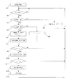
- FIG. 1 is a flowchart for explaining the flow of processing in the method for detecting the state of an electricity storage device of this embodiment
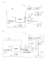
- FIG. 2 is a block diagram showing the configuration of the state detection device for the electricity storage device of this embodiment.
- a state detection device 100 detects the state of an electricity storage device (storage battery) 10 mounted in the target system 1.
- the target system 1 includes a charging unit 11 for charging the power storage device 10 and a control unit 12 for controlling charging by the charging unit 11.
- the load 20 mounted on the target system 1 is connected to the power storage device 10, and power is supplied from the power storage device 10 to the load 20.
- the power storage device 10 is provided with a voltage measurement unit 30 and a current measurement unit 31, and the state detection device 100 inputs each measurement value and performs state detection.
- the temperature measuring means 32 may be installed in the electricity storage device 10 as necessary, and a temperature measurement value of the electricity storage device 10 may be input and used for state detection.
- the state detection apparatus 100 includes a state detection unit 110, a storage unit 120, and a state output unit 130.
- the state detection unit 110 receives the voltage measurement value and the current measurement value of the electricity storage device 10 from the voltage measurement unit 30 and the current measurement unit 31, respectively, and performs processing according to the state detection method of the present embodiment to detect the state of the electricity storage device 10. I do.
- the temperature measuring means 32 may be installed in the power storage device 10 and a temperature measurement value may be input from this to be used for detecting the state of the power storage device 10.
- the storage unit 120 stores various reference data and measurement data necessary for the state detection process.
- the status output means 130 is means for notifying the user or the like of the status detection result or the like.
- the state detection device 100 may be incorporated in the control device 12 of the target system 1.
- the state detection device 100 may be provided outside the target system 1 and the measurement data recording device 40 that records measurement data may be provided inside the target system 1. Regardless of wired or wireless data, the data recorded in the measurement data recording device 40 is transmitted to the state detection device 100 installed outside the target system 1 by using remote communication or using a portable storage medium.
- the state may be input and the state may be determined to detect the state.
- the method for detecting the state of the electricity storage device is performed by measuring the OCV of the electricity storage device 10 in a process in which the internal state after the electricity storage device 10 stops charging and discharging (hereinafter referred to as a relaxation process).
- This is a method for detecting the state quantity.
- a state when the state detection device 100 determines that the condition for detecting the state is satisfied is referred to as a state detection mode.
- the predetermined state quantity detected by the state detection method of the present embodiment is any one of the remaining capacity (SOC) with respect to the full charge capacity of the electricity storage device 10, the degree of deterioration (SOH) with respect to the capacity when new, a discharge capacity, and a charge capacity. That's it.
- the OCV measured value is used.
- a predetermined voltage integrated value is calculated, and a predetermined state quantity is detected using this voltage integrated value.
- the influence of noise and local changes can be reduced.
- a method for calculating the integrated voltage value will be described below with reference to FIG.
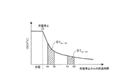
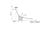
- FIG. 3 is an explanatory diagram illustrating an example of the change in the open-circuit voltage and the integrated voltage value of the electricity storage device in the relaxation process.
- the integrated voltage value is obtained by time integration of the open-circuit voltage in the period ta to tb, and corresponds to the area of the hatched portion shown in FIG.
- the period in which this integration is performed is referred to as an integration time region.
- the following can be used as a method for calculating such a voltage integral value.
- the integrated voltage value in the integrated time range ta to tb is expressed as S1 ta-tb
- the elapsed time from the charge / discharge stop is expressed as t
- the cycle (time interval) for measuring the open-circuit voltage is expressed as ⁇ t.
- a voltage calculation formula FV (t) is obtained by linearly approximating the measured values OCVta and OCVtb of the open-circuit voltages at times ta and tb, and the integrated voltage value S1 ta-tb is calculated using the above formula (1). calculate.
- a reference voltage calculation formula FV ref (t) is created in advance, and the correction parameter for FV ref (t) is adjusted based on the measured value of the open circuit voltage at least in the integration time range ta to tb.
- the voltage calculation formula FV (t) is obtained, and the voltage integrated value S1 ta-tb is calculated using the above formula (1).
- the integration time ranges ta to tb for time-integrating the open-circuit voltage can be appropriately set in advance, but are preferably set based on the change rate of the open circuit voltage after charging / discharging is stopped.
- a method of detecting the state quantity of the electricity storage device 10 using the voltage integrated value S1 ta-tb calculated by any one of the methods (1) to (4) will be described below.
- the state quantity of the electricity storage device 10 a method of detecting the SOC will be described.
- SOC detection it is preferable to use a correlation between the SOC change amount ( ⁇ SOC) changed from the previous state detection mode to the current state detection mode and the voltage integrated value.
- the state detection method of the present embodiment in order to detect the SOC by using the integrated voltage value S1 ta-tb, the relationship between the voltage accumulated value S1 ta-tb and [Delta] SOC, as the reference data created in the pre-stored unit Stored in 120.
- the reference data may be stored in the storage unit 120 as a reference function expressed in a predetermined function form.
- a reference function G1 (S1 ta-tb ) for calculating ⁇ SOC from the voltage integrated value S1 ta-tb is used below.
- the state quantity SOC of the electricity storage device 10 can be obtained in the state detection mode as follows.
- ⁇ SOC G1 (S1 ta-tb ) (3)
- SOC n SOC n-1 + ⁇ SOC (4)
- SOC n ⁇ 1 is the SOC obtained in the previous state detection mode
- SOC n represents the SOC obtained in the current state detection mode.
- the integrated time range is only one period from ta to tb.
- the present invention is not limited to this, and two or more integrated time ranges may be provided.
- an integrated time range of different time ranges tc to td is provided, and voltage integrated values S1 ta-tb and S1 tc-td are respectively provided. Is calculated.
- the reference function is a function G1 ′ (S1 ta-tb , S1 tc-td ) of the voltage integrated values S1 ta-tb and S1 tc-td , which is created in advance and stored in the storage unit 120.
- the SOC can be calculated with higher accuracy by obtaining the state quantity using the voltage integrated value in two or more integrated time regions.
- each integrated time region based on the change rate (relaxation rate) of the open-circuit voltage. That is, it is preferable to set the start time and time length of each integrated time region based on the change rate (relaxation rate) of the open-circuit voltage.
- the state quantity can be obtained by reflecting the voltage integrated values in the time regions having different relaxation rates, and the state detection can be performed with higher accuracy.
- the state detection method of the electrical storage device of this embodiment is demonstrated according to the flowchart of FIG.
- the state quantity to be detected is SOC
- the voltage integrated value S1 ta-tb is calculated by the method (1).
- the state detection unit 110 performs the process illustrated in FIG. 1, thereby detecting the state of the power storage device 10.
- reference data or reference functions necessary for state detection are stored in the storage unit 120 in advance.
- the OCV measurement value, the calculated SOC, and the like are also stored in the storage unit 120.
- the state detection unit 110 starts the state detection mode in accordance with a request from the inside or the outside of the state detection device 100 (step S1).
- the request from the inside of the state detection device 100 automatically determines that the conditions of the state detection mode such as charge / discharge stop are satisfied at every time interval ⁇ t for periodically performing the processing necessary for state detection. Sometimes done.
- a request from the outside of the state detection device 100 a request from a user of the target system 1 or maintenance personnel at the time of regular maintenance, or a request signal from a device in the target system 1 connected to the power storage device 10 Further, a request signal from an external system connected to the target system 1 can be considered.
- step S2 When the state detection is started, processing is performed periodically at a time interval ⁇ t.
- the state detection cycle is determined, and if ⁇ t has not elapsed since the previous state detection cycle, the process ends without waiting for the following processing. If it determines with it being a state detection period in step S2, it will be determined in step S3 whether the electrical storage device 10 is stopping charging / discharging.
- step S3 can be performed by inputting a current measurement value from the current measurement means and determining that charging / discharging is stopped when the current measurement value is smaller than a predetermined threshold value. If it is determined in step S3 that charging / discharging is stopped, the process proceeds to the next step S4. If it is determined that charging / discharging is not stopped (charging / discharging), the process proceeds to step S5. In step S5, since the condition of the state detection mode is not satisfied, the state detection mode is set to off.
- the state detection mode can be detected not only when the current of the electricity storage device 10 is 0, but also when the following current / voltage is measured.
- a small current (dark current) is consumed by a measuring instrument, controller, communication device, etc., but the effect on the relaxation amount can be corrected and is within an allowable range that can be regarded as a pseudo OCV.
- current exceeding the above allowable range is consumed, reference data is created based on the amount of relaxation measured in advance under the same conditions, and the reference data selected based on the current value is When used, the measured voltage can be handled as OCV. When any one of the above conditions is satisfied, it is possible to detect the state by treating the voltage measurement value as an OCV.
- step S4 it is determined whether or not charging / discharging has just been stopped. When it is determined that charging / discharging has just stopped, the process proceeds to step S6. Proceed to S8. Since the state detection mode is off when charging / discharging is not stopped in the previous detection cycle, it can be determined in step S4 that the charging / discharging has just stopped if the state detection mode is off. If it is determined in step S4 that it is not immediately after stopping charging / discharging, the time interval ⁇ t is added to the elapsed time t up to that point and updated in step S8, and then the process proceeds to step S9.
- step S4 when it is determined in step S4 that the charging / discharging has just stopped, the state detection mode is set to ON in step S6 and the number of executions of the state detection mode is updated (here, the number of executions is n). .
- the elapsed time t from the charge / discharge stop is initialized to zero. Then, it progresses to step S7.
- step S7 charge control or discharge control of a predetermined capacity is performed on the power storage device 10 as charge / discharge control before state detection.
- the amount of charge or the amount of discharge performed as the charge / discharge control before state detection is suitably determined according to the type, model number, capacity, combined quantity, etc. of the electricity storage device 10. As an example, in the case of a liquid lead-acid battery of JIS standard 55D23, it is desirable to carry out charging of about 5% in terms of new capacity.
- the charge / discharge control before state detection in step S7 can be omitted depending on the state of the relaxation process of the power storage device 10, the operation method of the target system 1, and the like.
- step S9 it is determined whether or not the elapsed time t is within the accumulated time range ta to tb. If it is determined that the elapsed time t is within the accumulated time range ta to tb, the process proceeds to the next step S10. If it is determined that the elapsed time t is outside the accumulated time range ta to tb, the process returns to step S2 and waits for the next cycle.
- step S ⁇ b> 10 the open end voltage of the electricity storage device 10 is input from the voltage measurement unit 30, and is stored in the storage unit 120 as the open end voltage measurement value OCVi. Then, it progresses to step S11.
- step S11 it is determined whether or not the elapsed time t is the end time tb of the integrated time range.
- the process proceeds to step S12.
- the voltage calculation formula FV (t) is optimally approximated using the open-circuit voltage measurement value OCVi stored in the storage unit 120 so far.
- the voltage integrated value S1 ta-tb is calculated from the equation (1) using the optimally approximated voltage calculation equation FV (t). Thereafter, the process proceeds to step S13.
- step S13 the reference function G1 (S1 ta-tb ) stored in advance in the storage unit 120 is read, and the integrated voltage value S1 ta-tb calculated in step S12 is substituted into the reference function G1 to obtain the SOC change amount ⁇ SOC. calculate. Then, the SOC change amount ⁇ SOC is added to the SOC so far stored in the storage unit 120 to update the SOC. The updated SOC is stored in the storage unit 120 and used in the next state detection mode, and is output to the state output unit 130 as appropriate.
- step S13 When the state quantity SOC is detected in step S13, the n-th state detection mode process is terminated. However, in order to monitor the establishment of the next state detection mode, the process returns to step S2 and waits until the next cycle. The state detection mode is kept on until the next charging / discharging is resumed. However, since the condition of step S9 is not satisfied, the process returns to step S2 without performing the processes after step S10. Then, when charging / discharging is resumed, the state detection mode is turned off in step S5, and after that, when charging / discharging is stopped, the state detection mode is set to ON again, and the processing after step S4 is performed.
- the SOC calculated in the previous state detection mode may be used.
- the voltage calculation formula FV (t) optimally approximated in the previous state detection mode is corrected using the open-circuit voltage measurement value OCVi stored in the storage unit 120 so far, and this is corrected with the reference function G1 (S1 It is also possible to estimate ⁇ SOC using ta-tb ).
- the voltage integration value is calculated for each, and ⁇ SOC is calculated using a reference function with the two or more voltage integration values as variables.
- a reference function can be prepared in advance so that ⁇ SOC can be calculated using some integration values.
- the state detection is performed using the voltage integrated value, it is possible to reduce the influence of noise and local fluctuations included in the voltage measurement value, Detection can be performed with high accuracy.
- complicated calculation such as regression calculation is not required, it is possible to provide a state detection method and a state detection device for a power storage device with reduced calculation processing load.
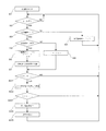
- FIG. 5 is a flowchart for explaining the flow of processing in the state detection method for the power storage device of the present embodiment.
- the integrated voltage value is obtained from the measured value OCVi of the open-ended voltage
- the integrated voltage value is calculated from the voltage drop amount V drop at which the open-ended voltage drops to a predetermined reference voltage.
- the reference voltage is an open-circuit voltage when a predetermined reference time (t base ) has elapsed since the charge / discharge stop.
- the reference voltage is the open-circuit voltage in the relaxation process. It may be set higher or lower. As an example, the reference voltage may be set to a value higher than the open end voltage at the start of relaxation immediately after stopping charging, or may be set to a value lower than the open end voltage at the start of relaxation immediately after stopping discharge. In any case, the voltage drop amount V drop is calculated by subtracting the reference voltage from the open end voltage.
- FIG. 6 shows a change in the open end voltage after the storage device 10 stops charging and a change in the open end voltage after the storage device 10 stops discharging.
- the open-circuit voltage in the relaxation process gradually approaches while decreasing (decreasing) toward the stable OCV.
- the electricity storage device 10 before the charge / discharge stop is discharging
- the open-ended voltage in the relaxation process gradually increases while increasing toward the stable OCV. Therefore, when the amount of voltage change with respect to the stable OCV is viewed as a voltage drop amount, the voltage drop amount is positive in the state detection after charging, whereas the voltage drop amount is negative in the state detection after discharge. Similarly, the integrated voltage value is positive in the state detection after charging, but negative in the state detection after discharging.
- the reference time t base is preferably an elapsed time until the relaxation rate of the electricity storage device 10 after the charge / discharge stop becomes relatively small.
- the reference voltage becomes a value close to the stable OCV, and thus the voltage drop amount V drop substantially corresponds to the transient voltage drop amount after the charge / discharge stop.
- the voltage integrated value an integrated value of the voltage drop amount V drop
- the correlation between the change amount of the state quantity such as the SOC and the integrated value of the voltage drop amount V drop is obtained with high accuracy to obtain reference data or reference. It can be a function.
- the calculation formula of the voltage integrated value S2 ta-tb is expressed as follows:
- OCV base represents a reference voltage.
- OCV_base ⁇ (tb ⁇ ta) is subtracted from the integral value of the voltage calculation formula FV (t). Accordingly, an effect is obtained that the number of operations for subtracting OCV_base can be reduced rather than integrating the optimal approximation (OCVi ⁇ OCV_base) by subtracting OCV_base for each open-ended voltage measurement value OCVi and performing optimal approximation.
- the reference data may be stored in the storage unit 120 as a reference function expressed in a predetermined function form.
- state detection after stopping charging is performed using reference data or a reference function for a positive voltage integrated value
- state detection after discharging is stopped using reference data or a reference function for a negative voltage integrated value. Therefore, the reference data or the reference function can be set and used with high accuracy separately after charging and after discharging.
- a reference function G2 (S2 ta-tb ) for calculating ⁇ SOC from the voltage integrated value S2 ta-tb is used.
- the latest SOC n calculated in the state detection mode is the SOC n ⁇ obtained in the previous state detection mode using ⁇ SOC calculated using the reference function G2 (S2 ta-tb ), as in the first embodiment. Calculated by adding to 1 .
- the state detection method of the electrical storage device of this embodiment is demonstrated according to the flowchart of FIG.
- the state quantity of the detection target is set as SOC
- the voltage integrated value S2 ta-tb is calculated using the equation (5).
- it demonstrates centering on the part from which 1st Embodiment differs in the processing content.
- the setting of ON / OFF of the state detection mode in steps S1 to S8 and the updating of the duration are performed in the same manner as in the first embodiment.
- step S23 the elapsed time t is equal to or a reference time t base, whereas when the reference time t base proceeds to step S24, when it is not the reference time t base is the next returns to step S2 Wait until the cycle.
- step S24 the voltage calculation formula FV (t) is optimally approximated using the open-circuit voltage measurement value OCVi in the accumulated time range ta to tb stored in the storage unit 120. Then, the voltage integrated value S2 ta-tb is calculated from the equation (5) using the optimally approximated voltage calculation formula FV (t) and the reference voltage OCV base (open end voltage measurement value OCVi at the reference time t base ). Thereafter, the process proceeds to step S25.
- step S25 the SOC change amount ⁇ SOC is calculated by reading the reference function G2 (S) stored in advance in the storage unit 120 and substituting the integrated voltage value S2 ta-tb calculated in step S24 for this. Then, the SOC change amount ⁇ SOC is added to the SOC in the previous state detection mode stored in the storage unit 120 to update the SOC. The updated SOC is stored in the storage unit 120 and used in the next state detection mode, and is output to the state output unit 130 as appropriate.
- two or more integration time zones can be provided, in which case the open-circuit voltage measurement value OCVi is acquired from the start time of the first integration time zone to the reference time t base, and the voltage in each integration time zone is obtained.
- the integrated value is calculated, and ⁇ SOC is calculated using a reference function having two or more voltage integrated values as variables.
- the state detection after the stop of charging is performed using the reference data or the reference function for the positive voltage integrated value, and the state detection after the discharge stop is performed for the negative voltage integrated value. Since the reference data or reference function can be used, the reference data or reference function can be set and used with high accuracy after charging and discharging, and the state quantity of the storage device can be detected with high accuracy. Is possible.
- FIG. 7 is a flowchart for explaining the flow of processing in the method for detecting the state of the electricity storage device of this embodiment.
- a method of obtaining the SOC as an example of the state quantity will be described.
- the state quantity is obtained based on the voltage integration value in the preset integration time range.
- the time point when the predetermined elapsed time is reached (integration The time integration of the voltage is sequentially performed from the start time point tp), and the elapsed time (referred to as ts) from the integration start time point ta when the voltage integration value reaches a predetermined threshold value (reference threshold value) is obtained and created in advance.
- ⁇ SOC corresponding to the elapsed time ts is obtained using reference data or a reference function of the elapsed time vs. ⁇ SOC.
- the integrated voltage value S i is calculated from the integrated time start point tp that has reached a predetermined elapsed time after stopping charging and discharging.
- the calculated voltage integrated value S i is compared with a reference threshold value (referred to as Sth), and when it is determined that the voltage integrated value S i is greater than or equal to the reference threshold value Sth, from the integration start time tp at that time ⁇ SOC corresponding to the elapsed time ts is obtained from reference data or a reference function. Then, the current state quantity SOC i is calculated by adding the obtained ⁇ SOC to the SOC i ⁇ 1 calculated in the previous state detection mode.
- Sth a reference threshold value
- a method for detecting the state of the electricity storage device of this embodiment will be described with reference to the flowchart of FIG. below, it demonstrates centering on the part from which 1st Embodiment differs in the processing content. Also in the present embodiment, the contents of the processing after step S9 in the processing flow of the state detection method of the first embodiment are different, and the setting of ON / OFF of the state detection mode in steps S1 to S8, the duration, etc. The update is performed in the same manner as in the first embodiment.
- step S31 it is determined whether or not the elapsed time t has reached the integration start time tp in step S31. After the elapsed time t has reached the integration start time tp, the processing from step S32 is performed for each cycle. Do. At step S32 obtains the open circuit voltage measurements OCVi, calculates the integrated voltage increment [Delta] S i in step S33. In step S34, the voltage integrated value S i is calculated by adding the voltage integrated increase amount ⁇ S i to the voltage integrated value S i-1 of the previous cycle. In step S35, it is determined whether or not the voltage integrated value S i is equal to or greater than the reference threshold value Sth.
- step S36 When it is determined that the voltage integrated value S i is equal to or greater than the reference threshold value Sth, in step S36, the elapsed time ts and reference data or reference at that time are determined.
- the current state quantity SOC i is calculated from the function.
- step S36 When the current state quantity SOC i is calculated in step S36, an appropriate flag or the like is provided to bypass steps S31 to S36 so that the processing in steps S31 to S36 is not performed in the next and subsequent cycles. deep.
- the calculation and determination processes of steps S33 to S36 are performed for each cycle, so that the load on the arithmetic processing unit of the state detection unit 110 increases, but the state detection is performed with high accuracy. be able to.
- the power storage device state detection method and apparatus includes, for example, an engine-driven automobile, an electric vehicle, a mobile phone, a backup battery that operates in the event of a power failure, and natural energy generated by sunlight or wind in cooperation with system power
- the present invention can be applied to an apparatus in which an electricity storage device such as an electricity storage device used for leveling the power of the power generation and a system incorporating the electricity storage device is mounted and monitoring or state detection is necessary.
- the power storage device to which the state detection method and the state detection device of the present invention are applied is a power storage device, a capacitor, or the like, and increases or decreases the energy inside the device by movement of electrons or ions, and the internal energy is externally supplied. It can be applied to a device that can be taken out as electric power. In other words, it is applicable not only to liquid lead storage devices mounted on automobiles, but also to Li-ion batteries, Ni-hydrogen batteries, sodium-sulfur batteries, capacitors, etc., and also to storage systems that combine these. it can.
- the description in the present embodiment shows an example of the state detection method and apparatus of the electricity storage device according to the present invention, and the present invention is not limited to this.
- the detailed configuration and detailed operation of the power storage device state detection method and the apparatus in the present embodiment can be appropriately changed without departing from the spirit of the present invention.
- Target system 10 Power storage device 11: Charging means 12: Control means 20: Load 30: Voltage measurement means 31: Current measurement means 32: Temperature measurement means 100: State detection device 110: State detection part 120: Storage part 130: Status output means
Landscapes
- Physics & Mathematics (AREA)
- General Physics & Mathematics (AREA)
- Secondary Cells (AREA)
- Charge And Discharge Circuits For Batteries Or The Like (AREA)
- Tests Of Electric Status Of Batteries (AREA)
Abstract
Description
本発明の第1の実施形態に係る蓄電デバイスの状態検知方法及び状態検知装置を、図1、2を用いて説明する。図1は、本実施形態の蓄電デバイスの状態検知方法における処理の流れを説明するためのフローチャートであり、図2は、本実施形態の蓄電デバイスの状態検知装置の構成を示すブロック図である。

S1ta-tb=OCVna×Δt+・・+OCVnb×Δt
=(OCVna+・・+OCVnb)×Δt (2)
(3)時間ta、tbにおけるそれぞれの開放端電圧の測定値OCVta、OCVtbで直線近似したものを電圧算出式FV(t)とし、上記式(1)を用いて電圧積算値S1ta-tbを算出する。
(4)参照用の電圧算出式FVref(t)を事前に作成しておき、少なくとも積算時間域ta~tbにおける開放端電圧の測定値をもとにFVref(t)に対する補正パラメータを調整して電圧算出式FV(t)を求め、上記式(1)を用いて電圧積算値S1ta-tbを算出する。
ΔSOC=G1(S1ta-tb) (3)
SOCn=SOCn-1+ΔSOC (4)
上式において、SOCn-1は前回の状態検知モードで求めたSOCであり、SOCnは今回の状態検知モードで求めるSOCを表す。
(1)計測器、制御器、通信機等で微小な電流(暗電流)が消費されているが、緩和量に与える影響が補正可能で擬似的にOCVとみなせる許容範囲にあるとき、
(2)上記の許容範囲を超える電流が消費されているが、同様の条件で事前に測定された緩和量をもとに参照データが作成され、電流値をもとに選択された参照データを用いることで測定電圧をOCVとして扱えるとき、
上記のいずれかの条件を満たす場合には、電圧測定値をOCVとして扱って状態検知を行うことが可能となる。
本発明の第2の実施形態に係る蓄電デバイスの状態検知方法を、図5を用いて説明する。図5は、本実施形態の蓄電デバイスの状態検知方法における処理の流れを説明するためのフローチャートである。第1実施形態では電圧積算値を開放端電圧の測定値OCViから求めるのに対し、本実施形態では開放端電圧が所定の基準電圧まで降下する電圧降下量Vdropから電圧積算値を算出するようにしている。ここで、上記の基準電圧は、充放電停止から所定の基準時間(tbaseとする)だけ経過したときの開放端電圧としている。

本発明の第3の実施形態に係る蓄電デバイスの状態検知方法を、図7を用いて説明する。図7は、本実施形態の蓄電デバイスの状態検知方法における処理の流れを説明するためのフローチャートである。ここでも、状態量の一例としてSOCを求める方法について説明する。
10:蓄電デバイス
11:充電手段
12:制御手段
20:負荷
30:電圧測定手段
31:電流測定手段
32:温度測定手段
100:状態検知装置
110:状態検知部
120:記憶部
130:状態出力手段
Claims (11)
- 蓄電デバイスの充電または放電を停止(以下では充放電停止という)した後の開放端電圧をもとに該蓄電デバイスの状態量を検知する蓄電デバイスの状態検知方法であって、
充放電停止後の所定期間における前記開放端電圧をもとに算出される電圧積算値から前記状態量を算出するための参照データまたは参照関数を事前に作成し、
前記蓄電デバイスの充放電停止後の前記所定期間に所定の時間間隔で前記開放端電圧の測定値を取得し、
前記開放端電圧測定値をもとに前記電圧積算値を算出し、
前記参照データまたは参照関数を用いて前記電圧積算値に対応する前記状態量を算出する
ことを特徴とする蓄電デバイスの状態検知方法。 - 所定の電圧算出式を前記開放端電圧測定値を用いて最適近似し、前記最適近似された電圧算出式を前記所定期間にわたって時間積分することで前記電圧積算値を算出する
ことを特徴とする請求項1に記載の蓄電デバイスの状態検知方法。 - 前記所定期間の前記開放端電圧測定値を加算し、これに前記時間間隔を乗じて前記電圧積算値を算出する
ことを特徴とする請求項1に記載の蓄電デバイスの状態検知方法。 - 充放電停止後の所定の基準時間が経過したときの開放端電圧を基準開放端電圧とするとき、
所定の電圧算出式を前記開放端電圧測定値を用いて最適近似し、前記最適近似された電圧算出式を前記所定期間にわたって時間積分し、
さらに、前記基準開放端電圧に前記所定期間を乗じたものを減算して前記電圧積算値を算出する
ことを特徴とする請求項1に記載の蓄電デバイスの状態検知方法。 - 充放電停止後の所定基準時間経過したときの開放端電圧を基準開放端電圧とするとき、
前記所定期間の前記開放端電圧測定値を加算したのち前記時間間隔を乗じ、
さらに、前記基準開放端電圧に前記所定期間を乗じたものを減算して前記電圧積算値を算出する
ことを特徴とする請求項1に記載の蓄電デバイスの状態検知方法。 - 蓄電デバイスの充電または放電を停止(以下では充放電停止という)した後の開放端電圧をもとに該蓄電デバイスの状態量を検知する蓄電デバイスの状態検知方法であって、
充放電停止後の所定の積算開始時点からの前記開放端電圧の積算値が所定の閾値に達するときの経過時間をもとに前記状態量を算出するための参照データまたは参照関数を事前に作成し、
前記蓄電デバイスの充放電停止後の前記積算開始時点から所定の時間間隔で前記開放端電圧の測定値を取得して前記積算値を算出し、
前記積算値が前記閾値に達したときの前記積算開始時点からの経過時間を求め、
前記参照データまたは参照関数を用いて前記経過時間に対応する前記状態量を算出する
ことを特徴とする蓄電デバイスの状態検知方法。 - 前記状態量は、前記参照データまたは参照関数を用いて算出された状態量変化量を前回の充放電停止後に算出された前回の状態量に加算して算出される
ことを特徴とする請求項1乃至6のいずれか1項に記載の蓄電デバイスの状態検知方法。 - 前記所定期間は、前記充放電停止後の前記開放端電圧の変化速度に基づいて選択された1以上の期間である
ことを特徴とする請求項1乃至7のいずれか1項に記載の蓄電デバイスの状態検知方法。 - 前記状態量は、前記蓄電デバイスの新品時の容量に対する劣化度(SOH)、満充電容量に対する残容量(SOC)、放電能力、充電能力のいずれか1以上である
ことを特徴とする請求項1乃至8のいずれか1項に記載の蓄電デバイスの状態検知方法。 - 蓄電デバイスの充電または放電を停止(以下では充放電停止という)した後の開放端電圧をもとに該蓄電デバイスの状態量を検知する蓄電デバイスの状態検知装置であって、
充放電停止後の所定期間における前記開放端電圧をもとに算出される電圧積算値から前記状態量を算出するための参照データまたは参照関数を事前に作成して保存する記憶部と、
前記蓄電デバイスの充放電停止後の前記所定期間に所定の時間間隔で前記開放端電圧の測定値を入力し、前記開放端電圧の測定値をもとに前記電圧積算値を算出し、前記参照データまたは参照関数を用いて前記電圧積算値に対応する前記状態量を算出する状態検知部と、
前記状態検知部から前記状態量を入力して外部に出力する状態出力手段と、を備える
ことを特徴とする蓄電デバイスの状態検知装置。 - 蓄電デバイスの充電または放電を停止(以下では充放電停止という)した後の開放端電圧をもとに該蓄電デバイスの状態量を検知する蓄電デバイスの状態検知装置であって、
充放電停止後の所定の積算開始時点からの前記開放端電圧の積算値が所定の閾値に達するときの経過時間をもとに前記状態量を算出するための参照データまたは参照関数を事前に作成して保存する記憶部と、
前記蓄電デバイスの充放電停止後の前記積算開始時点から所定の時間間隔で前記開放端電圧の測定値を入力し、前記開放端電圧の測定値をもとに前記電圧積算値を算出し、前記積算値が前記閾値に達したときの前記積算開始時点からの経過時間を求め、前記参照データまたは参照関数を用いて前記経過時間に対応する前記状態量を算出する状態検知部と、
前記状態検知部から前記状態量を入力して外部に出力する状態出力手段と、を備える
ことを特徴とする蓄電デバイスの状態検知装置。
Priority Applications (3)
| Application Number | Priority Date | Filing Date | Title |
|---|---|---|---|
| PCT/JP2010/070408 WO2012066643A1 (ja) | 2010-11-16 | 2010-11-16 | 蓄電デバイスの状態検知方法及びその装置 |
| JP2011524115A JP5823292B2 (ja) | 2010-11-16 | 2010-11-16 | 蓄電デバイスの状態検知方法及びその装置 |
| CN201080036072.1A CN102893169B (zh) | 2010-11-16 | 2010-11-16 | 蓄电设备的状态检测方法及其装置 |
Applications Claiming Priority (1)
| Application Number | Priority Date | Filing Date | Title |
|---|---|---|---|
| PCT/JP2010/070408 WO2012066643A1 (ja) | 2010-11-16 | 2010-11-16 | 蓄電デバイスの状態検知方法及びその装置 |
Publications (1)
| Publication Number | Publication Date |
|---|---|
| WO2012066643A1 true WO2012066643A1 (ja) | 2012-05-24 |
Family
ID=46083606
Family Applications (1)
| Application Number | Title | Priority Date | Filing Date |
|---|---|---|---|
| PCT/JP2010/070408 Ceased WO2012066643A1 (ja) | 2010-11-16 | 2010-11-16 | 蓄電デバイスの状態検知方法及びその装置 |
Country Status (3)
| Country | Link |
|---|---|
| JP (1) | JP5823292B2 (ja) |
| CN (1) | CN102893169B (ja) |
| WO (1) | WO2012066643A1 (ja) |
Cited By (4)
| Publication number | Priority date | Publication date | Assignee | Title |
|---|---|---|---|---|
| WO2012157747A1 (ja) * | 2011-05-18 | 2012-11-22 | 古河電気工業株式会社 | 組電池の制御方法及び制御装置 |
| CN117713273A (zh) * | 2023-10-31 | 2024-03-15 | 东莞市安泰电子科技有限公司 | 一种智能化电能管理系统 |
| AU2022263786B2 (en) * | 2021-04-28 | 2025-06-05 | Hitachi High-Tech Corporation | Battery state estimation device and power system |
| WO2025197446A1 (ja) * | 2024-03-22 | 2025-09-25 | パナソニックIpマネジメント株式会社 | 電池状態推定システム、電池状態推定方法、及び電池状態推定プログラム |
Families Citing this family (7)
| Publication number | Priority date | Publication date | Assignee | Title |
|---|---|---|---|---|
| CN103645441B (zh) * | 2013-11-29 | 2016-06-01 | 中国科学院金属研究所 | 一种钒电池运行过程中充/放电状态的判断方法 |
| CN105814446B (zh) * | 2014-01-14 | 2019-07-23 | 费森尤斯维尔公司 | 用于确定电池的剩余运行时间的方法和装置 |
| CN106104282A (zh) * | 2014-08-28 | 2016-11-09 | 单立辉 | 一种基于参考能量的电气测量方法 |
| CN104569841A (zh) * | 2014-12-26 | 2015-04-29 | 国家电网公司 | 电池组的老化检测方法和装置 |
| JP6807014B2 (ja) * | 2016-04-01 | 2021-01-06 | 株式会社Gsユアサ | 推定装置、推定方法 |
| CN108828448B (zh) * | 2018-06-08 | 2020-08-28 | 江苏大学 | 基于充电电压曲线融合卡尔曼滤波的电池荷电状态在线估算方法 |
| KR102780292B1 (ko) | 2019-12-11 | 2025-03-11 | 주식회사 엘지에너지솔루션 | 배터리 관리 시스템, 배터리 관리 방법, 배터리 팩 및 전기 차량 |
Citations (2)
| Publication number | Priority date | Publication date | Assignee | Title |
|---|---|---|---|---|
| JP2007178333A (ja) * | 2005-12-28 | 2007-07-12 | Toyota Motor Corp | 二次電池の劣化状態の推定方法と車載二次電池の劣化状態推定装置。 |
| JP2008096328A (ja) * | 2006-10-13 | 2008-04-24 | Furukawa Electric Co Ltd:The | 充電率推定方法、充電率推定装置及び二次電池電源システム |
Family Cites Families (5)
| Publication number | Priority date | Publication date | Assignee | Title |
|---|---|---|---|---|
| TW535308B (en) * | 2000-05-23 | 2003-06-01 | Canon Kk | Detecting method for detecting internal state of a rechargeable battery, detecting device for practicing said detecting method, and instrument provided with said |
| JP2001351696A (ja) * | 2000-06-02 | 2001-12-21 | Hitachi Ltd | 二次電池の充放電装置 |
| CN100573178C (zh) * | 2003-07-09 | 2009-12-23 | 古河电气工业株式会社 | 充电率推测方法、充电率推测装置和电池系统 |
| JP2007010588A (ja) * | 2005-07-01 | 2007-01-18 | Sanyo Electric Co Ltd | 車両用の電源装置 |
| CN101303397A (zh) * | 2008-06-25 | 2008-11-12 | 河北工业大学 | 锂离子电池组剩余电能计算方法及装置 |
-
2010
- 2010-11-16 JP JP2011524115A patent/JP5823292B2/ja active Active
- 2010-11-16 CN CN201080036072.1A patent/CN102893169B/zh not_active Expired - Fee Related
- 2010-11-16 WO PCT/JP2010/070408 patent/WO2012066643A1/ja not_active Ceased
Patent Citations (2)
| Publication number | Priority date | Publication date | Assignee | Title |
|---|---|---|---|---|
| JP2007178333A (ja) * | 2005-12-28 | 2007-07-12 | Toyota Motor Corp | 二次電池の劣化状態の推定方法と車載二次電池の劣化状態推定装置。 |
| JP2008096328A (ja) * | 2006-10-13 | 2008-04-24 | Furukawa Electric Co Ltd:The | 充電率推定方法、充電率推定装置及び二次電池電源システム |
Cited By (5)
| Publication number | Priority date | Publication date | Assignee | Title |
|---|---|---|---|---|
| WO2012157747A1 (ja) * | 2011-05-18 | 2012-11-22 | 古河電気工業株式会社 | 組電池の制御方法及び制御装置 |
| AU2022263786B2 (en) * | 2021-04-28 | 2025-06-05 | Hitachi High-Tech Corporation | Battery state estimation device and power system |
| CN117713273A (zh) * | 2023-10-31 | 2024-03-15 | 东莞市安泰电子科技有限公司 | 一种智能化电能管理系统 |
| CN117713273B (zh) * | 2023-10-31 | 2024-06-11 | 东莞市安泰电子科技有限公司 | 一种智能化电能管理系统 |
| WO2025197446A1 (ja) * | 2024-03-22 | 2025-09-25 | パナソニックIpマネジメント株式会社 | 電池状態推定システム、電池状態推定方法、及び電池状態推定プログラム |
Also Published As
| Publication number | Publication date |
|---|---|
| CN102893169B (zh) | 2015-06-17 |
| JPWO2012066643A1 (ja) | 2014-05-12 |
| CN102893169A (zh) | 2013-01-23 |
| JP5823292B2 (ja) | 2015-11-25 |
Similar Documents
| Publication | Publication Date | Title |
|---|---|---|
| JP5823292B2 (ja) | 蓄電デバイスの状態検知方法及びその装置 | |
| CN102428379B (zh) | 蓄电设备的状态检测方法及其装置 | |
| JP5619744B2 (ja) | 蓄電デバイスの状態検知方法及びその装置 | |
| US8175826B2 (en) | Apparatus for estimating open circuit voltage of battery, apparatus for estimating state of charge of battery, and method for controlling the same | |
| US10001528B1 (en) | Battery deterioration degree estimating apparatus and estimating method | |
| JP5179047B2 (ja) | 蓄電装置の異常検出装置、蓄電装置の異常検出方法及びその異常検出プログラム | |
| CN1102740C (zh) | 精确测定电池剩余容量的装置和方法 | |
| KR100845960B1 (ko) | 2차 전지의 충전 상태를 검출하기 위한 장치 | |
| JP4823974B2 (ja) | 蓄電池の残存容量検知方法及び残存容量検知装置 | |
| WO2017122758A1 (ja) | 蓄電素子管理装置、蓄電素子モジュール、車両および蓄電素子管理方法 | |
| EP3110654B1 (en) | Vehicle charge control device | |
| US9350191B2 (en) | Secondary-battery chargeable-limit detecting method and device of the same | |
| US20090248334A1 (en) | Method for estimating the charge of a motor vehicle battery | |
| JP2015215272A (ja) | 二次電池状態検出装置および二次電池状態検出方法 | |
| US20200195029A1 (en) | Charge control device, charge control method, non-transitory computer readable medium, control circuit and power storage system | |
| WO2018131651A1 (ja) | 電池パック及び電源システム | |
| JP2023101509A (ja) | 半導体装置、およびバッテリの残量の検出方法 | |
| JP5158872B2 (ja) | バッテリ状態検知方法、状態検知装置及びバッテリ電源システム | |
| JP5041442B2 (ja) | 蓄電デバイスの状態検知方法 | |
| CN117289158A (zh) | 电池soc的确定方法、装置、存储介质和电子设备 | |
| JP4897976B2 (ja) | 蓄電デバイスの状態検知方法及びその装置 | |
| KR102037149B1 (ko) | 온도 별 저항 값을 이용한 전류 측정 장치 및 그 방법 | |
| KR20230130238A (ko) | 배터리 상태 추정 방법 | |
| Majeed et al. | Hybrid fuel gauge approach based on incremental and low-current open-circuit voltage methods for continuous state-of-charge estimation in lithium-ion batteries | |
| CN119159995B (zh) | 车辆soc校正方法、装置、设备及存储介质 |
Legal Events
| Date | Code | Title | Description |
|---|---|---|---|
| WWE | Wipo information: entry into national phase |
Ref document number: 201080036072.1 Country of ref document: CN |
|
| WWE | Wipo information: entry into national phase |
Ref document number: 2011524115 Country of ref document: JP |
|
| 121 | Ep: the epo has been informed by wipo that ep was designated in this application |
Ref document number: 10859747 Country of ref document: EP Kind code of ref document: A1 |
|
| NENP | Non-entry into the national phase |
Ref country code: DE |
|
| 122 | Ep: pct application non-entry in european phase |
Ref document number: 10859747 Country of ref document: EP Kind code of ref document: A1 |