WO2012063533A1 - 画像処理装置 - Google Patents
画像処理装置 Download PDFInfo
- Publication number
- WO2012063533A1 WO2012063533A1 PCT/JP2011/068762 JP2011068762W WO2012063533A1 WO 2012063533 A1 WO2012063533 A1 WO 2012063533A1 JP 2011068762 W JP2011068762 W JP 2011068762W WO 2012063533 A1 WO2012063533 A1 WO 2012063533A1
- Authority
- WO
- WIPO (PCT)
- Prior art keywords
- image
- input
- optical flow
- reference image
- motion
- Prior art date
- Legal status (The legal status is an assumption and is not a legal conclusion. Google has not performed a legal analysis and makes no representation as to the accuracy of the status listed.)
- Ceased
Links
Images


Classifications
-
- G—PHYSICS
- G06—COMPUTING OR CALCULATING; COUNTING
- G06T—IMAGE DATA PROCESSING OR GENERATION, IN GENERAL
- G06T7/00—Image analysis
- G06T7/20—Analysis of motion
- G06T7/223—Analysis of motion using block-matching
-
- H—ELECTRICITY
- H04—ELECTRIC COMMUNICATION TECHNIQUE
- H04N—PICTORIAL COMMUNICATION, e.g. TELEVISION
- H04N23/00—Cameras or camera modules comprising electronic image sensors; Control thereof
- H04N23/80—Camera processing pipelines; Components thereof
-
- H—ELECTRICITY
- H04—ELECTRIC COMMUNICATION TECHNIQUE
- H04N—PICTORIAL COMMUNICATION, e.g. TELEVISION
- H04N23/00—Cameras or camera modules comprising electronic image sensors; Control thereof
- H04N23/80—Camera processing pipelines; Components thereof
- H04N23/81—Camera processing pipelines; Components thereof for suppressing or minimising disturbance in the image signal generation
-
- G—PHYSICS
- G06—COMPUTING OR CALCULATING; COUNTING
- G06T—IMAGE DATA PROCESSING OR GENERATION, IN GENERAL
- G06T2207/00—Indexing scheme for image analysis or image enhancement
- G06T2207/20—Special algorithmic details
- G06T2207/20172—Image enhancement details
- G06T2207/20201—Motion blur correction
Definitions
- the present invention relates to an image processing apparatus, and more particularly, to an image processing apparatus capable of improving the image quality of an image taken by a camera or the like when the image is deteriorated due to fluctuations caused by heat.
- Prior Art 1 discloses a method for restoring image degradation using the blind deconvolution method for an event such as camera shake that occurs during camera shooting. It is shown that a good image free from camera shake can be obtained with a simple configuration without using a sensor that detects a physical quantity such as a gyro sensor.
- an object of the present invention is to provide an image processing apparatus that can improve image quality deterioration due to an event caused by natural atmospheric factors such as a hot flame and obtain a good image.
- the image processing apparatus is sequentially input from the imaging apparatus in an imaging apparatus that captures a video (moving image, time-series image) of a target region and an image processing apparatus that processes the video captured by the imaging apparatus.
- a reference image estimation unit that estimates a reference image having no motion based on an input image, and an optical flow that detects a local fluctuation of the input image based on the input image and the reference image to detect a motion distribution due to a hot flame
- the calculation unit includes a calculation unit, and a motion correction unit that corrects the input image based on a distribution of movement caused by a hot flame detected by the optical flow calculation unit so as to remove local fluctuations in the input image.
- the reference image estimation unit may sequentially update the reference image by weighted addition of the current input image and the current reference image.
- the optical flow calculation unit may calculate the optical flow using at least one of a block matching method and a gradient method.
- the image processing apparatus of the present invention it is possible to correct image fluctuation due to the heat flame that could not be corrected by the conventional method 1, and to provide a good image.
- FIG. 1 is a configuration diagram of a monitoring apparatus to which an image processing apparatus of the present invention is applied. It is a figure explaining an example of the internal block diagram of the image processing apparatus of this invention. It is a figure explaining an example of the operation
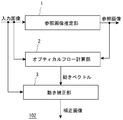
- FIG. 1 is a functional block diagram showing the configuration of a monitoring apparatus 100 to which the present invention is applied.
- the monitoring device 100 includes an imaging device 101 such as a surveillance camera, an image processing device 102 that inputs image data from the imaging device 101 and executes image processing of the present invention, image data (input image) input from the imaging device 101, An image output unit 103 that inputs image data (reference image, corrected image) output from the image processing apparatus 102 and outputs the image data is provided.
- the image output unit 103 can be configured by a monitor device including a video display unit.
- the image processing apparatus 102 includes a microcomputer, executes various programs by executing programs stored in the memory, and implements functions described below.
- FIG. 2 shows an example of an internal block diagram of the image processing apparatus 102 of the present embodiment.
- the image processing apparatus 102 according to the present exemplary embodiment includes a reference image estimation unit 1, an optical flow calculation unit 2, and a motion correction unit 3.
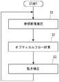
- FIG. 3 shows an example of a flowchart of the operation of the image processing apparatus 102 of the present embodiment.
- the operation of the reference image estimation unit 1 is executed in the reference image estimation step S1
- the operation of the optical flow calculation unit 2 is executed in the optical flow calculation step S2
- the operation of the motion correction unit 3 is executed in the motion correction step S3.
- the operation of each processing unit will be described.
- the reference image estimation unit 1 estimates an image (reference image) having no motion from an input image sequentially input from the imaging device 101 such as a camera.
- the imaging device 101 such as a camera.
- An image F t (x, y) input at a certain time t is input to the gain block 5 and multiplied by r, while a reference image R t (x, y) output from the delay unit 7 at a certain time t. y) is multiplied by 1-r in the gain block 6, and the output values of the gain block 5 and the gain block 6 are weighted and added by the adder 8.
- the output value of the adder 8 is input to the delay unit 7, and the delay unit 7 updates and outputs the data as the reference image R t + 1 (x, y) in the next frame (time t + 1).
- r in the gain blocks 5 and 6 is a weight, and is a constant that takes a value between 0 and 1.
- the delay unit 7 holds an image for a time interval of one frame. Therefore, the reference image calculated by the reference image estimation unit 1 is expressed as in Expression (1).
- R t + 1 (x, y) r ⁇ F t (x, y) + (1 ⁇ r) ⁇ R t (x, y) (1)
- Equation (1) is called Exponential Moving Average, and has the effect of reducing (averaging) high-frequency components of input images that are sequentially input.
- the input image finally weighted and added to the reference image has a weight equivalent to that obtained by averaging 100 frames of the input image. Imposed. That is, when the reference image estimation unit 1 is executed for each input image that is sequentially input, the input image having the number of frames indicated by the weight r is converged as an averaged image.
- This image is referred to as a reference image, and the reference image is an image having no motion by removing moving objects, fluctuations, and the like in the input image.
- the optical flow calculation unit 2 compares the input image with the reference image and calculates an optical flow in the optical flow calculation step S2.
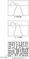
- the optical flow represents a local motion distribution between two images, for example, as shown in FIG. FIG. 5 is a diagram for explaining the calculation result of the optical flow calculation unit 2, FIG. 5 (a) shows a reference image, FIG. 5 (b) shows an input image, and FIG. 5 (c) shows an optical flow. Yes.
- the reference image is an image that does not move
- the input image is an image that is fluctuating due to a hot flame or the like. Therefore, the optical flows of the two images are locally random as shown in FIG. Distribution with a lot of movement.
- the local block pattern (template) of the reference image (FIG. 5A) is located at which position in the input image (FIG. 5B).
- a block matching method based on a process for searching whether there is a local area (for example, 10 pixels vertically and 10 pixels horizontally) of two images or the luminance of a certain pixel of interest
- a gradient method for calculating a motion vector from the difference between the spatial gradient of the level and the luminance level of the image of two frames.
- the optical flow calculation unit 2 it is possible to calculate the amount of local motion between two images of the input image (FIG. 5B) and the reference image (FIG. 5A). That is, it is possible to estimate how much fluctuation (motion vector) is generated by the hot flame in the target pixel on the input image (FIG. 5B).
- the motion correction unit 3 corrects the fluctuation due to the heat flame using the motion vector obtained by the optical flow calculation unit 2 in the motion correction step S3.
- the local region centered on the pixel of interest in the input image (FIG. 5B) For example, a partial image that is moved by ( ⁇ vx, ⁇ vy) is generated with respect to the partial image of 10 pixels in the above example and 10 pixels in the horizontal direction. That is, the moved partial image becomes a partial image in which the amount of movement due to the hot flame is corrected.
- This partial image generation process is performed for all the target pixels, and a superposition of all the partial images is output as a corrected image.
- an appropriate interpolation process may be performed in the process of moving the partial image described above.
- a reference image (FIG. 5 (a)) having no motion is estimated from an input image (FIG. 5 (b)) that is sequentially input, and the input image (FIG. 5 (b)) and the reference image are estimated.
- the optical flow (FIG. 5C) is calculated based on (FIG. 5A) to calculate the local fluctuation (motion vector) of the input image (FIG. 5B), and based on the motion vector. Then, a partial image of the input image (FIG. 5B) is moved so as to cancel the fluctuation of the heat flame, and a corrected image is generated by removing the fluctuation of the heat flame existing in the input image (FIG. 5B). Can do.
- the present embodiment improves the accuracy of the calculation result of the optical flow calculation unit 2 in the image processing apparatus shown in the first embodiment. Since the configuration of the processing unit of the present embodiment is the same as that of FIG. 2, the description of the configuration is omitted.
- the reference image estimation unit 1 averages the sequentially input images by the exponential moving average to obtain a reference image without motion.
- the movement of the moving object and the moving background component is removed.
- a phenomenon that constantly fluctuates like a hot flame appears as a blur on the reference image by averaging the input images.
- the optical flow calculation using the gradient method calculates a motion vector from the difference between the spatial gradient of the luminance level of a certain pixel of interest and the luminance level of the image of two frames. Are superimposed or there is a difference in luminance level between the input image and the reference image, there is a problem that the accuracy of the calculated optical flow is lowered.
- a method in which a high-pass filter that reduces blur on the reference image is applied to the reference image, or a low-pass filter that superimposes the same blur on the input image is applied to the input image. is there.
- a low-pass filter for example, a Gaussian filter
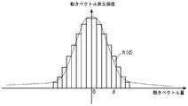
- FIG. 6 shows a histogram representing the amount of motion vector on the horizontal axis and the frequency of motion vector generation on the vertical axis.
- the motion vector amount is at least one of the elements vx or vy of the motion vector v at each point of interest, calculated in a predetermined number of frames (for example, 10 frames) in the past in the optical flow calculation unit 2 (the elements are real numbers). If it is represented, it is converted to an integer by a method such as rounding off or truncating to a small number), and this is set as the motion amount d.
- the occurrence frequency of the motion vector is the number of motion vectors taking the value of the motion amount d of the element.
- This histogram represents the distribution of the amount of fluctuation caused by the heat, and the frequency of occurrence decreases as the fluctuation increases, and thus the distribution is mountain-shaped around zero.
- the variance ⁇ 2 (standard deviation ⁇ ) of the shake distribution is calculated using this histogram. ⁇ 2 is expressed by equation (2).
- d represents the amount of movement
- h (d) represents the frequency of occurrence of the amount of movement d
- N represents the total number of target elements.
- the Gaussian filter is realized by a smoothing filter whose weight is a Gaussian function represented by the variance ⁇ 2 . This Gaussian function is expressed by Equation (3).
- the Gaussian filter described above the difference in luminance level due to blurring of the input image and the reference image is reduced, and the optical flow is calculated by reducing the noise of the input image, so the accuracy of the optical flow is improved. To do.
- the present embodiment improves the correction accuracy of the motion correction unit 3 in the image processing apparatus shown in the first or second embodiment. Since the configuration of the processing unit of the present embodiment is the same as that of FIG. 2, the description of the configuration is omitted.
- the optical flow calculation unit 2 calculates the local similarity between the input image and the reference image, the spatial gradient of the luminance level of the input image at the target pixel, and the difference between the luminance levels of the input image and the reference image. Calculate the motion vector.
- the local similarity decreases in the area where the object exists, and the difference between the luminance levels of the input image and the reference image becomes large, and an accurate motion vector cannot be calculated in the area where the object exists. is there.
- the reliability of the motion vector is evaluated based on the local similarity between the input image and the reference image.
- the similarity is, for example, the sum of absolute values of differences between luminance levels of the input image and the reference image (Sum of Absoluted Difference), or the normalized cross-correlation between the input image and the reference image (Normalized Cross-correlation: similarity) ).
- the degree of difference and the degree of similarity are described on pages 203 to 204 of Non-Patent Document 1.
- a predetermined threshold for example, 64 averaged by the number of pixels
- the image processing apparatus has no motion based on input images sequentially input from the imaging apparatus in an imaging apparatus that captures a target region and an image processing apparatus that processes video captured by the imaging apparatus.
- a reference image estimation unit for estimating a reference image; an optical flow calculation unit for calculating a local fluctuation of the input image based on the input image and the reference image;
- a motion correction unit that corrects the input image based on the distribution of motion caused by the hot flame detected by the optical flow calculation unit so as to remove local fluctuations.
- the reference image estimation unit of (1) may sequentially update the reference image by weighted addition of the current input image and the current reference image.
- the optical flow calculation unit of (1) and (2) may calculate the optical flow using at least one of a block matching method or a gradient method.
- the optical flow calculation unit when the optical flow calculation unit calculates an optical flow using a gradient method, the optical flow calculation unit inputs the input image before calculating the optical flow.
- a filter for example, a Gaussian filter
- the filtering characteristics of the filter of the optical flow calculation unit of (4) may be calculated based on the motion distribution detected by the optical flow calculation unit based on a predetermined number of frames in the past. Good.
- the optical flow calculation unit of (1) to (5) calculates the reliability of each motion vector of the detected motion distribution based on the local similarity between the input image and the reference image.
- the motion distribution may be corrected based on the reliability.
- the image processing apparatuses (1) to (6) may be provided in a monitoring apparatus that inputs and processes image data from the imaging apparatus.
- the present invention is not limited to the above-described monitoring device, and can be widely used for preventing image deterioration due to a positive flame (fluctuation in the refractive index of a medium such as the atmosphere) in various imaging devices.
Landscapes
- Engineering & Computer Science (AREA)
- Multimedia (AREA)
- Signal Processing (AREA)
- Computer Vision & Pattern Recognition (AREA)
- Physics & Mathematics (AREA)
- General Physics & Mathematics (AREA)
- Theoretical Computer Science (AREA)
- Image Processing (AREA)
- Image Analysis (AREA)
- Studio Devices (AREA)
Applications Claiming Priority (2)
| Application Number | Priority Date | Filing Date | Title |
|---|---|---|---|
| JP2010-253727 | 2010-11-12 | ||
| JP2010253727A JP5885384B2 (ja) | 2010-11-12 | 2010-11-12 | 画像処理装置 |
Publications (1)
| Publication Number | Publication Date |
|---|---|
| WO2012063533A1 true WO2012063533A1 (ja) | 2012-05-18 |
Family
ID=46050691
Family Applications (1)
| Application Number | Title | Priority Date | Filing Date |
|---|---|---|---|
| PCT/JP2011/068762 Ceased WO2012063533A1 (ja) | 2010-11-12 | 2011-08-19 | 画像処理装置 |
Country Status (2)
| Country | Link |
|---|---|
| JP (1) | JP5885384B2 (enExample) |
| WO (1) | WO2012063533A1 (enExample) |
Cited By (4)
| Publication number | Priority date | Publication date | Assignee | Title |
|---|---|---|---|---|
| WO2014069103A1 (ja) * | 2012-10-29 | 2014-05-08 | 株式会社日立国際電気 | 画像処理装置 |
| WO2014148114A1 (ja) * | 2013-03-21 | 2014-09-25 | 株式会社日立国際電気 | 画像処理装置、撮像装置、監視システム、符号化装置、画像処理方法 |
| GB2553646A (en) * | 2016-08-12 | 2018-03-14 | Hensoldt Optronics Gmbh | Method for processing frames of an input video image |
| CN110213495A (zh) * | 2013-02-28 | 2019-09-06 | 株式会社尼康 | 摄像装置、电子设备及图像处理方法 |
Families Citing this family (4)
| Publication number | Priority date | Publication date | Assignee | Title |
|---|---|---|---|---|
| JP5680524B2 (ja) | 2011-12-09 | 2015-03-04 | 株式会社日立国際電気 | 画像処理装置 |
| JP5787456B2 (ja) * | 2013-02-14 | 2015-09-30 | 株式会社日立国際電気 | 画像処理装置 |
| JP6435936B2 (ja) * | 2015-03-16 | 2018-12-12 | 株式会社リコー | プログラム、画像処理装置および画像処理システム |
| WO2018123202A1 (ja) * | 2016-12-28 | 2018-07-05 | シャープ株式会社 | 動画像処理装置、表示装置、動画像処理方法、および制御プログラム |
Citations (5)
| Publication number | Priority date | Publication date | Assignee | Title |
|---|---|---|---|---|
| JPH0395686A (ja) * | 1989-09-08 | 1991-04-22 | Matsushita Giken Kk | 画像処理方法 |
| JPH0530495A (ja) * | 1991-07-17 | 1993-02-05 | Nippon Hoso Kyokai <Nhk> | 勾配法による動きベクトル検出方法 |
| JP2002329193A (ja) * | 2001-04-27 | 2002-11-15 | Communication Research Laboratory | 歪画像補正方法及び装置 |
| JP2003187221A (ja) * | 2001-12-14 | 2003-07-04 | Sigma Solutions:Kk | 画像の周期的輝度ゆらぎ補正アルゴリズム |
| JP2004145628A (ja) * | 2002-10-24 | 2004-05-20 | Sharp Corp | 動きベクトル検出装置 |
Family Cites Families (4)
| Publication number | Priority date | Publication date | Assignee | Title |
|---|---|---|---|---|
| JPH06180749A (ja) * | 1992-12-14 | 1994-06-28 | Toyota Motor Corp | 路上物体監視装置 |
| JP2005208847A (ja) * | 2004-01-21 | 2005-08-04 | Fuji Xerox Co Ltd | 画像欠陥検出装置、画像形成装置 |
| US7526102B2 (en) * | 2005-09-13 | 2009-04-28 | Verificon Corporation | System and method for object tracking and activity analysis |
| JP2008202949A (ja) * | 2007-02-16 | 2008-09-04 | Omron Corp | 欠陥検査方法および欠陥検査装置 |
-
2010
- 2010-11-12 JP JP2010253727A patent/JP5885384B2/ja active Active
-
2011
- 2011-08-19 WO PCT/JP2011/068762 patent/WO2012063533A1/ja not_active Ceased
Patent Citations (5)
| Publication number | Priority date | Publication date | Assignee | Title |
|---|---|---|---|---|
| JPH0395686A (ja) * | 1989-09-08 | 1991-04-22 | Matsushita Giken Kk | 画像処理方法 |
| JPH0530495A (ja) * | 1991-07-17 | 1993-02-05 | Nippon Hoso Kyokai <Nhk> | 勾配法による動きベクトル検出方法 |
| JP2002329193A (ja) * | 2001-04-27 | 2002-11-15 | Communication Research Laboratory | 歪画像補正方法及び装置 |
| JP2003187221A (ja) * | 2001-12-14 | 2003-07-04 | Sigma Solutions:Kk | 画像の周期的輝度ゆらぎ補正アルゴリズム |
| JP2004145628A (ja) * | 2002-10-24 | 2004-05-20 | Sharp Corp | 動きベクトル検出装置 |
Non-Patent Citations (1)
| Title |
|---|
| HAJIME SONEHARA: "Motion Detection in consideration of a Boundary of Moving Object", ITEJ TECHNICAL REPORT, vol. 19, no. 62, 17 November 1995 (1995-11-17), pages 61 - 68 * |
Cited By (8)
| Publication number | Priority date | Publication date | Assignee | Title |
|---|---|---|---|---|
| WO2014069103A1 (ja) * | 2012-10-29 | 2014-05-08 | 株式会社日立国際電気 | 画像処理装置 |
| JP5706594B2 (ja) * | 2012-10-29 | 2015-04-22 | 株式会社日立国際電気 | 画像処理装置 |
| US9292934B2 (en) | 2012-10-29 | 2016-03-22 | Hitachi Kokusai Electric Inc. | Image processing device |
| CN110213495A (zh) * | 2013-02-28 | 2019-09-06 | 株式会社尼康 | 摄像装置、电子设备及图像处理方法 |
| CN110213495B (zh) * | 2013-02-28 | 2021-11-05 | 株式会社尼康 | 摄像装置、电子设备及图像处理方法 |
| WO2014148114A1 (ja) * | 2013-03-21 | 2014-09-25 | 株式会社日立国際電気 | 画像処理装置、撮像装置、監視システム、符号化装置、画像処理方法 |
| JP2014206772A (ja) * | 2013-03-21 | 2014-10-30 | 株式会社日立国際電気 | 画像処理装置、撮像装置、監視システム、符号化装置、画像処理方法 |
| GB2553646A (en) * | 2016-08-12 | 2018-03-14 | Hensoldt Optronics Gmbh | Method for processing frames of an input video image |
Also Published As
| Publication number | Publication date |
|---|---|
| JP2012104018A (ja) | 2012-05-31 |
| JP5885384B2 (ja) | 2016-03-15 |
Similar Documents
| Publication | Publication Date | Title |
|---|---|---|
| JP5680524B2 (ja) | 画像処理装置 | |
| JP5885384B2 (ja) | 画像処理装置 | |
| KR101071352B1 (ko) | 좌표맵을 이용한 팬틸트줌 카메라 기반의 객체 추적 장치 및 방법 | |
| US10404917B2 (en) | One-pass video stabilization | |
| US10769798B2 (en) | Moving object detection apparatus, moving object detection method and program | |
| KR100985805B1 (ko) | 적응적인 칼만필터를 이용한 영상 안정화 장치 및 방법 | |
| US7221776B2 (en) | Video stabilizer | |
| JP4454657B2 (ja) | ぶれ補正装置及び方法、並びに撮像装置 | |
| US20140254951A1 (en) | Deblurring of an image from a sequence of images | |
| CN103929568A (zh) | 用于稳定数字图像帧的第一序列的方法以及图像稳定单元 | |
| US20180061014A1 (en) | Contrast Adaptive Video Denoising System | |
| WO2017001096A1 (en) | Static soiling detection and correction | |
| CN110401784B (zh) | 自适应调节滤波强度的运动平滑方法、系统及视频设备 | |
| JP2008259161A (ja) | 目標追尾装置 | |
| JP5059855B2 (ja) | 大域的動き推定方法 | |
| JP2012085205A (ja) | 画像処理装置、撮像装置、画像処理方法および画像処理プログラム | |
| JP2021005206A (ja) | 画像処理装置、画像処理方法、およびプログラム | |
| KR101772928B1 (ko) | 휘도 평활화와 광흐름 분석을 이용한 이동탐지 시스템 및 방법 | |
| CN120224017A (zh) | 视频图像稳定控制方法、系统、电子设备及存储介质 | |
| CN112465728B (zh) | 视频图像处理方法、系统、电子设备及存储介质 | |
| Zhang et al. | Qualitative assessment of video stabilization and mosaicking systems | |
| US20230276127A1 (en) | Image processing apparatus and image processing method | |
| KR100856474B1 (ko) | 영상 흔들림 보정방법 | |
| CN120166182A (zh) | 一种基于双流图像的实时视频防抖稳像方法及系统 | |
| Hossain et al. | A novel accuracy assessment model for video stabilization approaches based on background motion |
Legal Events
| Date | Code | Title | Description |
|---|---|---|---|
| 121 | Ep: the epo has been informed by wipo that ep was designated in this application |
Ref document number: 11839115 Country of ref document: EP Kind code of ref document: A1 |
|
| NENP | Non-entry into the national phase |
Ref country code: DE |
|
| 122 | Ep: pct application non-entry in european phase |
Ref document number: 11839115 Country of ref document: EP Kind code of ref document: A1 |