WO2012060220A1 - Fibre optique d'amplification, et amplificateur à fibre optique et oscillateur mettant en oeuvre ladite fibre - Google Patents
Fibre optique d'amplification, et amplificateur à fibre optique et oscillateur mettant en oeuvre ladite fibre Download PDFInfo
- Publication number
- WO2012060220A1 WO2012060220A1 PCT/JP2011/073955 JP2011073955W WO2012060220A1 WO 2012060220 A1 WO2012060220 A1 WO 2012060220A1 JP 2011073955 W JP2011073955 W JP 2011073955W WO 2012060220 A1 WO2012060220 A1 WO 2012060220A1
- Authority
- WO
- WIPO (PCT)
- Prior art keywords
- mode
- optical fiber
- core
- light
- region
- Prior art date
Links
Images


Classifications
-
- H—ELECTRICITY
- H01—ELECTRIC ELEMENTS
- H01S—DEVICES USING THE PROCESS OF LIGHT AMPLIFICATION BY STIMULATED EMISSION OF RADIATION [LASER] TO AMPLIFY OR GENERATE LIGHT; DEVICES USING STIMULATED EMISSION OF ELECTROMAGNETIC RADIATION IN WAVE RANGES OTHER THAN OPTICAL
- H01S3/00—Lasers, i.e. devices using stimulated emission of electromagnetic radiation in the infrared, visible or ultraviolet wave range
- H01S3/05—Construction or shape of optical resonators; Accommodation of active medium therein; Shape of active medium
- H01S3/06—Construction or shape of active medium
- H01S3/063—Waveguide lasers, i.e. whereby the dimensions of the waveguide are of the order of the light wavelength
- H01S3/067—Fibre lasers
- H01S3/06708—Constructional details of the fibre, e.g. compositions, cross-section, shape or tapering
- H01S3/06729—Peculiar transverse fibre profile
- H01S3/06733—Fibre having more than one cladding
-
- G—PHYSICS
- G02—OPTICS
- G02B—OPTICAL ELEMENTS, SYSTEMS OR APPARATUS
- G02B6/00—Light guides; Structural details of arrangements comprising light guides and other optical elements, e.g. couplings
- G02B6/02—Optical fibres with cladding with or without a coating
- G02B6/036—Optical fibres with cladding with or without a coating core or cladding comprising multiple layers
- G02B6/03605—Highest refractive index not on central axis
- G02B6/03611—Highest index adjacent to central axis region, e.g. annular core, coaxial ring, centreline depression affecting waveguiding
-
- H—ELECTRICITY
- H01—ELECTRIC ELEMENTS
- H01S—DEVICES USING THE PROCESS OF LIGHT AMPLIFICATION BY STIMULATED EMISSION OF RADIATION [LASER] TO AMPLIFY OR GENERATE LIGHT; DEVICES USING STIMULATED EMISSION OF ELECTROMAGNETIC RADIATION IN WAVE RANGES OTHER THAN OPTICAL
- H01S3/00—Lasers, i.e. devices using stimulated emission of electromagnetic radiation in the infrared, visible or ultraviolet wave range
- H01S3/05—Construction or shape of optical resonators; Accommodation of active medium therein; Shape of active medium
- H01S3/06—Construction or shape of active medium
- H01S3/063—Waveguide lasers, i.e. whereby the dimensions of the waveguide are of the order of the light wavelength
- H01S3/067—Fibre lasers
- H01S3/06708—Constructional details of the fibre, e.g. compositions, cross-section, shape or tapering
- H01S3/0672—Non-uniform radial doping
-
- H—ELECTRICITY
- H01—ELECTRIC ELEMENTS
- H01S—DEVICES USING THE PROCESS OF LIGHT AMPLIFICATION BY STIMULATED EMISSION OF RADIATION [LASER] TO AMPLIFY OR GENERATE LIGHT; DEVICES USING STIMULATED EMISSION OF ELECTROMAGNETIC RADIATION IN WAVE RANGES OTHER THAN OPTICAL
- H01S3/00—Lasers, i.e. devices using stimulated emission of electromagnetic radiation in the infrared, visible or ultraviolet wave range
- H01S3/05—Construction or shape of optical resonators; Accommodation of active medium therein; Shape of active medium
- H01S3/08—Construction or shape of optical resonators or components thereof
- H01S3/08018—Mode suppression
- H01S3/0804—Transverse or lateral modes
-
- H—ELECTRICITY
- H01—ELECTRIC ELEMENTS
- H01S—DEVICES USING THE PROCESS OF LIGHT AMPLIFICATION BY STIMULATED EMISSION OF RADIATION [LASER] TO AMPLIFY OR GENERATE LIGHT; DEVICES USING STIMULATED EMISSION OF ELECTROMAGNETIC RADIATION IN WAVE RANGES OTHER THAN OPTICAL
- H01S3/00—Lasers, i.e. devices using stimulated emission of electromagnetic radiation in the infrared, visible or ultraviolet wave range
- H01S3/05—Construction or shape of optical resonators; Accommodation of active medium therein; Shape of active medium
- H01S3/06—Construction or shape of active medium
- H01S3/063—Waveguide lasers, i.e. whereby the dimensions of the waveguide are of the order of the light wavelength
- H01S3/067—Fibre lasers
- H01S3/0675—Resonators including a grating structure, e.g. distributed Bragg reflectors [DBR] or distributed feedback [DFB] fibre lasers
-
- H—ELECTRICITY
- H01—ELECTRIC ELEMENTS
- H01S—DEVICES USING THE PROCESS OF LIGHT AMPLIFICATION BY STIMULATED EMISSION OF RADIATION [LASER] TO AMPLIFY OR GENERATE LIGHT; DEVICES USING STIMULATED EMISSION OF ELECTROMAGNETIC RADIATION IN WAVE RANGES OTHER THAN OPTICAL
- H01S3/00—Lasers, i.e. devices using stimulated emission of electromagnetic radiation in the infrared, visible or ultraviolet wave range
- H01S3/09—Processes or apparatus for excitation, e.g. pumping
- H01S3/091—Processes or apparatus for excitation, e.g. pumping using optical pumping
- H01S3/094—Processes or apparatus for excitation, e.g. pumping using optical pumping by coherent light
- H01S3/094003—Processes or apparatus for excitation, e.g. pumping using optical pumping by coherent light the pumped medium being a fibre
-
- H—ELECTRICITY
- H01—ELECTRIC ELEMENTS
- H01S—DEVICES USING THE PROCESS OF LIGHT AMPLIFICATION BY STIMULATED EMISSION OF RADIATION [LASER] TO AMPLIFY OR GENERATE LIGHT; DEVICES USING STIMULATED EMISSION OF ELECTROMAGNETIC RADIATION IN WAVE RANGES OTHER THAN OPTICAL
- H01S3/00—Lasers, i.e. devices using stimulated emission of electromagnetic radiation in the infrared, visible or ultraviolet wave range
- H01S3/09—Processes or apparatus for excitation, e.g. pumping
- H01S3/091—Processes or apparatus for excitation, e.g. pumping using optical pumping
- H01S3/094—Processes or apparatus for excitation, e.g. pumping using optical pumping by coherent light
- H01S3/094069—Multi-mode pumping
-
- H—ELECTRICITY
- H01—ELECTRIC ELEMENTS
- H01S—DEVICES USING THE PROCESS OF LIGHT AMPLIFICATION BY STIMULATED EMISSION OF RADIATION [LASER] TO AMPLIFY OR GENERATE LIGHT; DEVICES USING STIMULATED EMISSION OF ELECTROMAGNETIC RADIATION IN WAVE RANGES OTHER THAN OPTICAL
- H01S3/00—Lasers, i.e. devices using stimulated emission of electromagnetic radiation in the infrared, visible or ultraviolet wave range
- H01S3/09—Processes or apparatus for excitation, e.g. pumping
- H01S3/091—Processes or apparatus for excitation, e.g. pumping using optical pumping
- H01S3/094—Processes or apparatus for excitation, e.g. pumping using optical pumping by coherent light
- H01S3/09408—Pump redundancy
-
- H—ELECTRICITY
- H01—ELECTRIC ELEMENTS
- H01S—DEVICES USING THE PROCESS OF LIGHT AMPLIFICATION BY STIMULATED EMISSION OF RADIATION [LASER] TO AMPLIFY OR GENERATE LIGHT; DEVICES USING STIMULATED EMISSION OF ELECTROMAGNETIC RADIATION IN WAVE RANGES OTHER THAN OPTICAL
- H01S3/00—Lasers, i.e. devices using stimulated emission of electromagnetic radiation in the infrared, visible or ultraviolet wave range
- H01S3/09—Processes or apparatus for excitation, e.g. pumping
- H01S3/091—Processes or apparatus for excitation, e.g. pumping using optical pumping
- H01S3/094—Processes or apparatus for excitation, e.g. pumping using optical pumping by coherent light
- H01S3/0941—Processes or apparatus for excitation, e.g. pumping using optical pumping by coherent light of a laser diode
- H01S3/09415—Processes or apparatus for excitation, e.g. pumping using optical pumping by coherent light of a laser diode the pumping beam being parallel to the lasing mode of the pumped medium, e.g. end-pumping
-
- H—ELECTRICITY
- H01—ELECTRIC ELEMENTS
- H01S—DEVICES USING THE PROCESS OF LIGHT AMPLIFICATION BY STIMULATED EMISSION OF RADIATION [LASER] TO AMPLIFY OR GENERATE LIGHT; DEVICES USING STIMULATED EMISSION OF ELECTROMAGNETIC RADIATION IN WAVE RANGES OTHER THAN OPTICAL
- H01S3/00—Lasers, i.e. devices using stimulated emission of electromagnetic radiation in the infrared, visible or ultraviolet wave range
- H01S3/14—Lasers, i.e. devices using stimulated emission of electromagnetic radiation in the infrared, visible or ultraviolet wave range characterised by the material used as the active medium
- H01S3/16—Solid materials
- H01S3/1601—Solid materials characterised by an active (lasing) ion
- H01S3/1603—Solid materials characterised by an active (lasing) ion rare earth
- H01S3/1618—Solid materials characterised by an active (lasing) ion rare earth ytterbium
Definitions
- the present invention relates to an optical fiber for amplification, and an optical fiber amplifier and resonator using the same, and more particularly, an optical fiber for amplification capable of improving beam quality, and an optical fiber amplifier and resonator using the same.
- an optical fiber for amplification capable of improving beam quality
- an optical fiber amplifier and resonator using the same about.
- the light generated by a seed light source such as a laser oscillator (MO: Master Oscillator) is amplified by an amplifier (PA: Power Amplifier) and output.
- An MO-PA Master-Oscillator-Power Amplifier
- an optical fiber amplifier that amplifies light by an amplification optical fiber is known.
- a double clad fiber in which an active element such as a rare earth element is added to a core is generally used.
- This double clad fiber includes a double clad fiber whose core propagates only single mode light and a double clad fiber whose core propagates multimode light.
- the core since the cross-sectional area of the core is small, the density of light propagating through the core may become too high when trying to obtain a high-power laser output. In this case, the energy of light shifts to an undesired wavelength due to the nonlinear optical effect, and an expected laser output may not be obtained. Therefore, with the recent demand for higher output of optical fiber amplifiers, optical fiber amplifiers using a double clad fiber whose core propagates multimode light have attracted attention.
- the optical fiber amplifier it is preferable from the viewpoint of improving the beam quality of the output light that the LP01 mode of the propagating light is amplified and the other higher-order modes are not amplified.
- the following patent document describes an example of such an optical fiber amplifier.
- this optical fiber amplifier it has been shown that, by arranging a mode converter that excites only the LP01 mode of light, even an amplifying double clad fiber that propagates multimode light can be amplified around the LP01 mode.
- an active optical element is added to the center of the core of the double-clad fiber, and an amplification optical fiber to which no active element is added is used at the outer periphery of the core. It has been suggested that the LP01 mode is more effectively amplified than the higher order modes.
- Patent Document 2 does not require an amplification optical fiber in which an active element is added to the center of the core of a double clad fiber and an absorbing element that absorbs light is added to the outer periphery of the core. The idea of attenuating high-order modes is described.
- the shape of the mode field of the input seed light and the LP01 mode of light propagating through the amplifying double-clad fiber are used. It is necessary to match the shape of the mode field. According to the knowledge of the present inventors, it is relatively easy not to excite the LP11 mode, which is an asymmetric mode among higher order modes, but the LP02 mode and LP03 mode, which are axially symmetric modes, are easily excited. In addition, higher-order modes such as the LP02 mode and the LP03 mode generally have a higher amplification ratio than the LP01 mode, even when the power is small at the time of input or when it occurs in the amplification optical fiber. For this reason, the present inventors have found that the output light occupies a high ratio. It has been found that the higher the light amplification factor, the higher the higher-order mode amplification ratio and the lower the beam quality of the output light.
- the present invention provides an optical fiber for amplification that can output light of good beam quality even when a higher-order mode is excited, and an optical fiber amplifier and a resonator using the optical fiber. With the goal.
- the inventors of the present invention describe how the LP01 mode, the LP02 mode, and the LP03 mode are in the radial direction of the core. We sought to determine whether it was distributed and amplified. As a result, it has been found that the LP02 mode and the LP03 mode are stronger than the LP01 mode at the center of the core. Therefore, if the active element is uniformly added to the radial direction of the core or if the active element is added at a high concentration in the center of the core, the LP02 mode and the LP03 mode have a high amplification factor as described above. It will be amplified. For this reason, it came to the conclusion that the beam quality of output light will worsen. Therefore, the present inventors have made further investigations and made the present invention.
- the amplifying optical fiber of the present invention provides a amplification optical fiber having a cladding covering the core, said core at least LP01 mode light having a predetermined wavelength, and, LP02 mode, And when the LP01 mode, the LP02 mode, and the LP03 mode are normalized by power, the strength of the LP01 mode is at least one of the LP02 mode and the LP03 mode.
- the active element that stimulates and emits light of the predetermined wavelength is added at a higher concentration than the central portion of the core, and satisfies at least one of the following formulas 1 and 2 It is characterized by this.
- I 01 (r) is the strength at a distance r from the center in the radial direction of the core in the LP01 mode
- I 02 (r) is the is the intensity from the center at a distance r in the radial direction of the core of the LP02 mode
- I 03 (r) is the intensity at a distance r from the center in the radial direction of the core of the LP03 mode
- n (r ) Is the concentration of the active element added at a distance r from the center in the radial direction of the core
- b is the radius of the core.
- the active element in a region where the LP01 mode is stronger than at least one of the LP02 mode and the LP03 mode, the active element is added at a higher concentration than the central portion of the core. In the region where the active element is added at a higher concentration than the central portion of the core, light is amplified at a higher amplification factor than the central portion of the core.
- the LP01 mode can be amplified with a higher amplification factor than at least one of the LP02 mode and the LP03 mode. Furthermore, since at least one of the above formulas 1 and 2 is satisfied, the LP01 mode can be amplified with a higher amplification factor than the LP02 mode and the LP03 mode as a whole fiber. Can be improved.
- the core has a region where the strength of the LP01 mode is higher than the strength of the LP02 mode when the LP01 mode, the LP02 mode, and the LP03 mode are normalized by power.
- the active element is added at a concentration higher than that of the central portion of the core in at least a part of a region where the intensity of the LP01 mode is higher than that of the LP03 mode, And it is preferable to satisfy both of the above-mentioned formula 2.
- the LP01 mode is amplified higher than the LP02 mode in a region where the LP01 mode is stronger than the LP02 mode, and the LP01 mode is stronger than the LP03 mode. In the stronger region, the LP01 mode is amplified higher than the LP03 mode.
- the LP01 mode as a whole is amplified with a higher amplification factor than both the LP02 mode and the LP03 mode.
- the beam quality can be improved.
- the LP01 mode intensity when the LP01 mode, the LP02 mode, and the LP03 mode are normalized by power is set to the intensity of the LP02 mode and the LP03 mode.
- the active element is preferably added at a higher concentration than the central portion of the core.
- an active element it is only necessary to add an active element to at least a part of a region where the intensity of the LP01 mode is stronger than both the LP02 mode and the LP03 mode.
- the active element can be efficiently added so that the amplification factor is higher than that of both the LP03 mode and the LP03 mode.
- the core includes, in the case where the LP01 mode, the LP02 mode, and the LP03 mode are normalized by power, the strength of the LP01 mode is the strength of the LP02 mode and the LP03 mode. It is preferable that the active element is added at a concentration higher than that of the central portion of the core in all regions stronger than the strength.
- the beam quality can be further improved.
- the core has an intensity of the LP01 mode when the LP01 mode, the LP02 mode, and the LP03 mode are normalized with power, at least of the LP02 mode and the LP03 mode.
- the active element is added at a concentration higher than that of the central portion of the core and satisfy both the formula 1 and the formula 2.
- the LP01 mode is amplified with a higher amplification factor in the entire region where the intensity of the LP01 mode is stronger than at least one of the LP02 mode and the LP03 mode. Therefore, the beam quality of the output light can be improved.
- the active element is not added to the central portion of the core.
- the concentration of the active element is lower in the outer peripheral portion of the core than in a region where the active element is added at a higher concentration than the central portion of the core.
- the present inventors have further found that the LP02 mode and the LP03 mode are stronger than the LP01 mode in the outer peripheral portion of the core. Therefore, according to such an optical fiber for amplification, the amplification factor of the LP02 mode and the LP03 mode is higher than the amplification factor of the LP01 mode in the outer peripheral portion where the strength of the LP02 mode and the LP03 mode is stronger than that of the LP01 mode. Since it can be kept low, the beam quality of the output light can be made better.
- the amplification optical fiber it is preferable that no active element is added to the outer peripheral portion of the core.
- the beam quality of the output light can be further improved.
- a pair of stress applying portions sandwiching the core is provided in the clad.
- the light propagating through the core can be made into a single polarization.
- the optical fiber amplifier according to the present invention includes the amplification optical fiber, a seed light source for inputting seed light including an LP01 mode to the amplification optical fiber, and excitation for exciting the active element of the amplification optical fiber. And an excitation light source that outputs light.
- the LP01 mode is amplified with a higher amplification factor, so that light with good beam quality can be output.
- the seed light input to the amplification optical fiber excites only an axially symmetric mode of the amplification optical fiber.
- the non-axisymmetric higher-order mode since the non-axisymmetric higher-order mode does not propagate in the amplification optical fiber, the non-axisymmetric higher-order mode is not amplified and output. Easy to output light with good beam quality.
- the seed light input to the amplification optical fiber is preferably single mode light.
- a resonator according to the present invention is provided on the one side of the amplification optical fiber, an excitation light source that outputs excitation light for exciting the active element of the amplification optical fiber, and the amplification optical fiber.
- a first FBG Fiber Bragg Grating
- a second FBG that reflects light having the same wavelength as the light reflected by the 1FBG with a reflectance lower than that of the first FBG.
- the LP01 mode in light resonance, when light propagates through the core of the amplification optical fiber, the LP01 mode is amplified more strongly than the LP02 mode and the LP03 mode. Compared with the case of using a uniformly added fiber, it is possible to output light with a good beam quality, in which the intensity of the LP01 mode is higher than the intensity of the LP02 mode and the LP03 mode.
- an optical fiber for amplification capable of outputting light of good beam quality even when a higher mode is excited, an optical fiber amplifier using the optical fiber, and a resonance A vessel is provided.
- FIG. 1 It is a figure which shows the resonator which concerns on 5th Embodiment of this invention. It is a figure which shows the modification of the optical fiber for amplification in 1st Embodiment. It is a figure which shows the beam quality of the output light in Example 1, 2, and the comparative example 1. FIG. It is a figure which shows the beam quality of the output light in Example 3, 4 and the comparative example 2. FIG. It is a figure which shows the beam quality of the output light in Example 5, 6 and the comparative example 3.
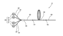
- FIG. 1 is a diagram showing an optical fiber amplifier according to a first embodiment of the present invention.
- an optical fiber amplifier 1 includes a seed light source 10 that outputs light serving as seed light, a pump light source 20 that outputs pump light, and an optical combiner that receives seed light and pump light. 30 and the amplification optical fiber 50 to which the seed light and the pumping light output from the optical combiner 30 are input and the active element excited by the pumping light is added.
- the seed light source 10 includes, for example, a semiconductor laser device, a Fabry-Perot type, or a fiber ring type fiber laser device.
- the seed light source 10 is configured to output light including an LP01 mode from an optical fiber.
- the seed light output from the seed light source 10 is not particularly limited as long as it is light including the LP01 mode, but the wavelength can stimulate and emit the active element added to the amplification optical fiber 50.
- the active element is ytterbium (Yb)
- the wavelength is 1070 nm.
- the output light of the seed light source 10 is output from the single mode fiber 15 composed of the core and the clad covering the core.
- the single mode fiber 15 propagates light output from the seed light source 10 as LP01 mode single mode light.
- the configuration of the single mode fiber 15 is not particularly limited. For example, when the wavelength of the seed light is 1070 nm as described above, the core diameter is 10 ⁇ m, and the relative refraction between the core and the clad is made. The rate difference is 0.13%.
- the excitation light source 20 is composed of a plurality of laser diodes 21.
- the laser diode 21 is a Fabry-Perot type semiconductor laser made of a GaAs-based semiconductor, for example, and outputs light having a center wavelength of 915 nm. To do.
- Each laser diode 21 of the excitation light source 20 is connected to the multimode fiber 22, and the excitation light output from the laser diode 21 propagates through the multimode fiber 22 as multimode light.
- the optical combiner 30 to which the multimode fiber 22 and the single mode fiber 15 are connected is configured by melting and extending a portion where the multimode fiber is disposed around the single mode fiber 15 as a center,
- the optical fiber 50 is optically connected to the amplification optical fiber 50.
- FIG. 2 is a diagram showing a structure in a cross section perpendicular to the longitudinal direction of the amplification optical fiber 50.
- the amplification optical fiber 50 includes a core 51, a clad 52 that covers the core 51, and an outer clad 53 that covers the clad 52.
- the refractive index of the cladding 52 is lower than the refractive index of the core 51, and the refractive index of the outer cladding 53 is lower than the refractive index of the cladding 52.
- the relative refractive index difference between the core 51 and the clad 52 is 0.32%.
- the core 51 has a diameter of, for example, 30 ⁇ m
- the cladding 52 has an outer diameter of, for example, 420 ⁇ m
- the outer cladding 53 has an outer diameter of, for example, 440 ⁇ m.
- the material constituting the core 51 includes, for example, quartz to which an element such as aluminum that increases the refractive index of quartz is added, and is output from the excitation light source 20 to at least a partial region of the core 51.
- Ytterbium (Yb) which is an active element that is excited by the excitation light is added.
- examples of such active elements include rare earth elements such as neodymium (Nd) and erbium (Er).
- active elements include bismuth (Bi), chromium (Cr), and the like.
- the material constituting the clad 52 includes, for example, quartz to which no dopant is added, and the material constituting the outer clad 53 includes, for example, an ultraviolet curable resin.
- the core 51 and the clad 52 Due to the difference in refractive index between the core 51 and the clad 52 as described above, light having a predetermined wavelength from the seed light source is confined and propagated in the core 51.
- modes of light propagating through the core 51 in addition to the LP01 mode, which is a basic mode, LP02 mode and LP03 mode exist as higher-order modes.
- the wavelength of the seed light, the dimensions of the core 51 and the clad 52, and the relative refraction of the core 51 and the clad 52 are prevented so that higher-order modes higher than LP04 do not propagate.
- the rate difference is set.
- the wavelength of the seed light is 1070 nm
- the diameter of the core 51 is 30 ⁇ m
- the core 51 and the cladding 52 The relative refractive index difference may be 0.32%.
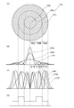
- FIG. 3 is a diagram showing a state of the core 51 of the amplification optical fiber 50 shown in FIG.
- FIG. 3A shows the structure of the core 51 in a cross section perpendicular to the longitudinal direction of the amplification optical fiber 50.
- FIG. 3B is a diagram showing the distribution of intensity per unit area normalized in the LP01 mode, the LP02 mode, and the LP03 mode propagating through the core 51.
- FIG. 3C is a diagram showing a normalized power distribution obtained by integrating the intensity of the LP01 mode, the LP02 mode, and the LP03 mode propagating through the core 51 by the area.
- 3D is a diagram showing a state of concentration distribution of the active element added to the core 51.
- FIG. 3A shows the structure of the core 51 in a cross section perpendicular to the longitudinal direction of the amplification optical fiber 50.
- FIG. 3B is a diagram showing the distribution of intensity per unit area normalized in the LP01 mode, the LP02 mode, and
- each mode has an intensity distribution that is strongest at the center of the core 51.
- the intensity at this center is the largest in the LP03 mode, followed by the LP02 mode, and the intensity in the LP01 mode is the smallest.
- strength of LP01 mode will become larger than the intensity
- a region in the radial direction from the center of the core 51 until the strength of the LP01 mode becomes larger than the strength of the LP03 mode is defined as a region A.
- strength of LP01 mode will become larger than the intensity
- a region where the intensity of the LP01 mode on the outer peripheral side of the region A becomes larger than the strengths of the LP02 mode and the LP03 mode is defined as a region B.
- a region until the strength of the LP03 mode temporarily becomes larger than the strength of the LP01 mode is defined as a region C, and the strength of the LP03 mode is temporarily larger than the strength of the LP01 mode.
- the area that is in question is area D.
- the strength of the LP01 mode is higher than the strength of the LP02 mode and the LP03 mode.
- a region where the intensity of the LP01 mode is larger than the strength of the LP02 mode and the LP03 mode on the outer periphery side of the region D is defined as a region E.
- the strength of the LP02 mode is larger than the strength of the LP01 mode, and further, on the outer peripheral side, the strength of the LP01 mode is smaller than the strength of the LP02 mode and the LP03 mode.
- a region where the intensity of the LP01 mode becomes smaller than the strength of the LP02 mode and the LP03 mode on the outer periphery side of the region E is defined as a region F, and a region on the outer periphery side of the region F is defined as a region G.
- the region A has a circular shape in a cross section perpendicular to the length direction of the core 51, and the other regions B to G are distributed in a ring shape.
- the diameter of the core 51 is 30 ⁇ m as described above
- the distance from the center to the boundary between the region A and the region B is about 3 ⁇ m
- the distance between the center and the region B and the region C is The distance to the boundary
- the distance from the center to the boundary between the region C and the region D is about 7 ⁇ m
- the distance from the center to the boundary between the region D and the region E is about 8.5 ⁇ m.
- the distance from the center to the boundary between the region E and the region F is about 10 ⁇ m
- the distance from the center to the boundary between the region F and the region G is about 12 ⁇ m.
- the intensity of the LP01 mode is smaller than the intensity of the LP02 mode and the LP03 mode.
- the LP01 mode intensity is greater than one of the LP02 mode and LP03 mode intensity.
- the intensity of the LP01 mode is larger than that of the LP02 mode and the LP03 mode.
- the strength of the LP01 mode is at least partly higher than the strength of at least one of the LP02 mode and the LP03 mode.
- the active element is added at a higher concentration than the central part of the core. That is, Yb, which is one of the active elements, is added at a concentration higher than that of the central portion of the core 51 in at least a part of the ring-shaped regions B to F in the region.
- I 01 (r) is the intensity at the distance r from the center in the radial direction of the core 51 of the LP01 mode shown in FIG. 02 (r) is the intensity at a distance r from the center in the radial direction of the LP02 mode of the core 51 shown in B of FIG. 3, I 03 (r), the diameter of the LP03 mode of the core 51 shown in B of FIG. 3
- the intensity at a distance r from the center in the direction, n (r) is the additive concentration of the active element at the distance r from the center in the radial direction of the core 51, and b is the radius of the core 51.
- the unit of r is (m), the unit of I 01 (r), I 02 (r) I 03 (r) is (W / m 2 ), and the unit of n (r) is (Pieces / m 3 ), and the unit of b is (m).
- 8 ⁇ 10 25 (pieces / m 3 ) of the active element Yb is added to the central region 55 including the center of the core 51, and the outside of the central region 55 is added.
- 16 ⁇ 10 25 (pieces / m 3 ) of the active element Yb is added to the outer peripheral region 57.
- the boundary between the central region 55 and the outer peripheral region 57 is included in the region C.
- the addition concentration of the active element Yb in the region C and the region E in which the intensity of the LP01 mode is stronger than the intensity of the LP02 mode and the LP03 mode Is higher than the additive concentration of the active element Yb in the central region 55 at the center of the active core.
- the additive concentration of the active element Yb in the central region 55 and the additive concentration of the active element Yb in the outer peripheral region 57 are set so as to satisfy the relationship of the equations 1 and 2. That is, as long as the concentration distribution of the active element in the core 51 satisfies the relationship of Equation 1 and Equation 2, the LP01 mode can be amplified with a higher amplification factor than the LP02 mode and LP03 mode, and the output The beam quality of the light to be made can be made good.
- the characteristic point of the present invention is that the LP01 mode intensity when the LP01 mode, the LP02 mode, and the LP03 mode are normalized by the power in order to satisfy the relationship of Expression 1 and Expression 2 is the LP02 mode.
- the active element is added at a higher concentration than the central portion of the core.
- seed light is output from the seed light source 10 from the single mode fiber 15.
- the wavelength of this seed light is, for example, 1070 ⁇ m as described above.
- only the LP01 mode propagates due to the configuration of the single mode fiber 15 described above.
- the LP01 mode light propagating through the single mode fiber 15 is input to the optical combiner 30.
- the excitation light source 20 outputs excitation light that excites the active element Yb added to the core 51 of the amplification optical fiber 50.
- the wavelength at this time is, for example, a wavelength of 915 ⁇ m as described above. Then, the excitation light output from the excitation light source 20 propagates through the multimode fiber 22 and is input to the optical combiner 30.
- the seed light and the pumping light input to the optical combiner 30 are input to the amplification optical fiber 50, the seed light propagates through the core 51 of the amplification optical fiber 50, and the pumping light is clad of the amplification optical fiber 50. 52 and the core 51 are propagated.
- the seed light is mainly input as the LP01 mode
- the core 51 of the amplification optical fiber 50 can propagate as the LP01 mode, the LP02 mode, and the LP03 mode with respect to the light having the wavelength of the seed light.
- the LP02 mode and the LP03 mode are excited and propagate as the LP01 mode, the LP02 mode, and the LP03 mode.
- the active element Yb added to the core 51 is excited.
- the excited active element Yb causes stimulated emission by seed light, and the seed light in the LP01 mode, LP02 mode, and LP03 mode is amplified by this stimulated emission.
- the concentration of the active element Yb in the outer peripheral region 57 of the core 51 is made higher than the concentration of the active element Yb in the central region 55 including the central portion of the core 51, and the above formulas 1 and 2 are satisfied.
- the LP01 mode is amplified at a higher amplification factor than the LP02 mode and the LP03 mode.
- the active element Yb is added at a low concentration, so that the amplification of the LP02 mode and LP03 mode light is suppressed.
- the core 51 outputs the seed light amplified with the amplification factor higher than that of the LP02 mode and the LP03 mode from the amplification optical fiber 50 as output light. Therefore, in the output light, the power of the LP02 mode and the LP03 mode is suppressed low, and the power of the LP01 mode is increased. Thus, output light with good beam quality is output.
- the active element is added at a low concentration in the central portion of the core 51 where the strength of the LP02 mode and the LP03 mode is strong. Mode amplification is suppressed.
- the light is amplified more strongly than the central portion of the core 51.
- the region where the light is strongly amplified includes more regions where the LP01 mode is stronger than at least one of the LP02 mode and the LP03 mode, and as a whole, the center region and the outer peripheral region satisfy the expressions 1 and 2.
- the LP01 mode is amplified with a higher amplification factor than the LP02 mode and the LP03 mode as the entire core 51. Since LP01 is amplified at a high amplification factor in this way, the beam quality of the output light can be improved.
- the amplification optical fiber 50 has a stronger LP01 mode strength than the LP02 mode and LP03 mode strength compared to a fiber in which the concentration of the active element Yb is uniformly added to the core 51.
- the single mode light composed of the LP01 mode is input to the amplification optical fiber 50 as the seed light, so that the excited LP02 mode and LP03 mode powers can be kept small. And the LP01 mode can be further amplified. Therefore, light with good beam quality can be output.
- FIG. 4 is a view showing a state of the core of the amplification optical fiber according to the second embodiment of the present invention, and is a view corresponding to FIG. 3 in the first embodiment.
- the amplification optical fiber in this embodiment uses a core 51a instead of the core 51 of the amplification optical fiber 50 in the first embodiment.
- the core 51a is divided into a central region 55a and an outer peripheral region 57a in the same manner as the core 51 of the first embodiment is divided into a central region 55 and an outer peripheral region 57.
- region 57a is adding the active element with the density
- the core 51a of the amplification optical fiber of the present embodiment is different from the core 51 of the amplification optical fiber 50 of the first embodiment in that no active element is added to the central region 55a. And addition of the active element of the core 51a is set so that the relationship of the said Formula 1 and Formula 2 may be satisfy
- the core 51a as a whole has a higher amplification factor in the LP01 mode than in the LP02 mode and the LP03 mode. Amplified.
- the amplification optical fiber of the present embodiment since the active element is not added to the center portion of the core having strong LP02 mode and LP03 mode strength, the LP02 mode and LP03 mode are not amplified in the center portion of the core. Accordingly, since the LP01 mode can be amplified with a higher amplification factor than the LP02 mode and the LP03 mode as a whole, the beam quality of the output light can be improved. Therefore, by using the amplification optical fiber of this embodiment, an optical fiber amplifier that can output light with better beam quality can be obtained.
- FIG. 5 is a diagram illustrating a state of the core of the amplification optical fiber according to the third embodiment of the present invention, and corresponds to FIG. 3 in the first embodiment.
- the amplification optical fiber in the embodiment uses a core 51b instead of the core 51 of the amplification optical fiber 50 in the first embodiment.
- the core 51b the core 51 of the first embodiment is divided into an outer peripheral region 57 in the central region 55, whereas an intermediate region 56b is provided between the central region 55b and the outer peripheral region 57b.
- the central region 55b has the same diameter and the concentration of the active element to be added as the central region 55 of the first embodiment. Accordingly, the boundary between the central region 55b and the intermediate region 56b is included in the region C as in the first embodiment. Further, as shown in FIG.
- the intermediate region 56b is added with an active element at the same concentration as the outer peripheral region 57 of the core 51 in the first embodiment, and the boundary between the intermediate region 56b and the outer peripheral region 57b. Is substantially equal to the boundary between the region E and the region F.
- the additive concentration of the active element in the outer peripheral region 57b is set lower than the additive concentration of the active element in the outer peripheral region 57 of the first embodiment. Therefore, the outer peripheral region 57b has an active element concentration lower than that of the intermediate region 56b.
- the additive concentration of the active element in the outer peripheral region 57b is the same as the additive concentration of the active element in the central region 55b.
- the addition concentration of the active element Yb in the region C and the region E where the intensity of the LP01 mode is stronger than that of the LP02 mode and the LP03 mode Is higher than the additive concentration of the active element Yb in the central region 55b in the central portion of the active core and in the outer peripheral region including the outer peripheral portion of the core.
- the core 51b is set so as to satisfy the relationship of Formula 1 and Formula 2.
- the active element concentrations in the central region 55b and the outer peripheral region 57b of the core 51b in which the LP02 mode and the LP03 mode are stronger than the LP01 mode are kept low.
- the central region 55b and the outer peripheral region 57b including the region A and the region G where the intensity is strong amplification of the LP02 mode and the LP03 mode is suppressed.
- region C and region E which are regions where the LP01 mode is stronger than the LP02 mode and LP03 mode, and the LP01 mode strength than the LP02 mode strength
- the LP01 mode is amplified with a high amplification factor.
- the amplification in the LP02 mode and the LP03 mode can be suppressed in the center region 55b and the outer peripheral region 57b. Since the active element is added so as to satisfy 2, the LP01 mode can be amplified with a higher amplification factor than the LP02 mode and the LP03 mode as a whole, so that the beam quality of the output light is further improved. Can be good. Therefore, by using the amplification optical fiber of this embodiment, an optical fiber amplifier that can output light with better beam quality can be obtained.
- FIG. 6 is a diagram illustrating a state of the core of the amplification optical fiber according to the fourth embodiment of the present invention, and corresponds to FIG. 3 in the first embodiment.
- the amplification optical fiber in the embodiment uses a core 51c in place of the core 51b of the amplification optical fiber in the third embodiment.
- the core 51c is divided into a central region 55c, an intermediate region 56c, and an outer peripheral region 57c in the same manner as the core 51b of the third embodiment is divided into a central region 55b, an intermediate region 56b, and an outer peripheral region 57b.
- an active element is added at the same concentration as the intermediate region 56b of the core 51b in the third embodiment.
- the core 51c of the amplification optical fiber of this embodiment is different from the core 51b of the third embodiment in that no active element is added to the central region 55c and the outer peripheral region 57c. Therefore, when the LP01 mode, the LP02 mode, and the LP03 mode are normalized by the power, the concentration of the active element Yb in the region C and the region E in which the intensity of the LP01 mode is stronger than the intensity of the LP02 mode and the LP03 mode. Is higher than the additive concentration of the active element Yb in the central region 55b of the central portion of the active core and the outer peripheral region which is the outer peripheral portion of the core.
- the core 51c is set so as to satisfy the relationship of Formula 1 and Formula 2.
- no active element is added in the central region 55c and the outer peripheral region 57c of the core 51c in which the LP02 mode and the LP03 mode are stronger than the LP01 mode.
- the central region 55c and the outer peripheral region 57c including the strong region A and region G the LP02 mode and the LP03 mode are not amplified.
- region C and region E which are regions where the intensity of the LP01 mode is stronger than that of the LP02 mode and LP03 mode, and the intensity of the LP01 mode than the intensity of the LP02 mode
- the LP01 mode is amplified with a high amplification factor.
- the LP02 mode and the LP03 mode are not amplified in the central region 55c and the outer peripheral region 57c, and as described above, the core 51c satisfies the above formulas 1 and 2. Since the active element is added as described above, the LP51 mode can be amplified with a higher amplification factor than the LP02 mode and the LP03 mode as a whole, so that the beam quality of the output light is improved. be able to. Therefore, by using the amplification optical fiber of this embodiment, an optical fiber amplifier that can output light with better beam quality can be obtained.
- FIG. 7 is a diagram showing a resonator according to the fifth embodiment of the present invention.
- the resonator 2 includes a double clad provided between the excitation light source 20, the amplification optical fiber 50, the optical combiner 30, and the amplification optical fiber 50 and the optical combiner 30.
- a fiber 65, a first FBG 61 provided in the double clad fiber 65, a multimode fiber 66 provided on the side opposite to the double clad fiber 65 side of the amplification optical fiber 50, and a second FBG 62 provided in the multimode fiber 66 are mainly used.
- the double clad fiber 65 has a cross-sectional structure perpendicular to the longitudinal direction similar to that of the optical fiber for amplification, and is composed of a core, a clad covering the core, and an outer clad covering the clad.
- the outer diameter and refractive index of the core, clad, and outer clad of the double clad fiber 65 are substantially the same as the core, clad, and outer clad of the amplification optical fiber 50.
- the first embodiment in the same manner as the amplification optical fiber 50 is connected to the optical combiner 30, one end of the double clad fiber 65 is connected to the optical combiner 30 and the core of the multimode fiber 22 is connected.
- the clad of the double clad fiber 65 is optically connected.
- the other end of the double clad fiber 65 is connected to the amplification optical fiber 50, the core of the double clad fiber 65 and the core 51 of the amplification optical fiber 50 are connected, and the clad of the double clad fiber 65 and the amplification light are connected.
- the clad 52 of the fiber 50 is connected.
- the first FBG 61 is provided in the core of the double clad fiber 65.
- the first FBG 61 is provided on one side of the amplification optical fiber 50.
- the first FBG 61 has a portion where the refractive index increases at a constant period along the longitudinal direction of the double clad fiber 65, and this period is adjusted so that the amplification optical fiber 50 in the excited state is in the excited state.
- the active element is configured to reflect at least part of the wavelength of light emitted. When the active element is Yb as described above, the first FBG 61 has a reflectance of, for example, 100% at 1070 nm, for example.
- the multimode fiber 66 provided on the opposite side of the amplification optical fiber 50 from the double clad fiber 65 side propagates the LP01 mode, the LP02 mode, and the LP03 mode in the same manner as the amplification optical fiber 50.
- the refractive indexes of the core and the clad are set.
- the multimode fiber 66 has one end connected to the amplification optical fiber 50 and nothing connected to the other end, and is a free end.
- the core 51 of the amplification optical fiber 50 and the multimode fiber 66 are connected to each other. The core is connected.
- the second FBG 62 is provided in the core of the multimode fiber 66.
- the second FBG 62 is provided on the other side of the amplification optical fiber 50.
- the second FBG 62 has a portion where the refractive index is increased at a constant period along the longitudinal direction of the multimode fiber 66, and light having the same wavelength as the light reflected by the first FBG 61 is reflected at a lower reflectance than the first FBG 61.
- the first FBG 61 is configured to reflect light having the same wavelength as that reflected by the first FBG 61 with a reflectance of 50%.
- the pumping light when pumping light is output from each laser diode 21 of the pumping light source 20, the pumping light is input to the cladding of the double-clad fiber 65 in the optical combiner 30, and the double-clad fiber. Input from 65 clads to the clad of the optical fiber 50 for amplification.
- the active element added to the core 51 of the amplification optical fiber 50 is brought into an excited state. And the active element made into the excited state emits spontaneous emission light of a specific wavelength.
- the spontaneously emitted light at this time is, for example, light having a constant band with a center wavelength of 1070 nm.
- This spontaneously emitted light propagates through the core 51 of the amplification optical fiber 50, is reflected by the first FBG 61 provided in the core of the double clad fiber 65, and the reflected light is reflected by the second FBG 62, so that the light Resonance occurs.
- the light is amplified when propagating through the core 51 of the amplification optical fiber 50, and part of the light is transmitted through the second FBG and output from the multimode fiber 66.
- the LP01 mode when the light propagates through the core 51 of the amplification optical fiber 50, the LP01 mode is amplified more strongly than the LP02 mode light, so that the concentration of the active element Yb is uniformly added to the core 51. Compared with the case of using a fiber, it is possible to output light with good beam quality, which has a higher LP01 mode light intensity than the LP02 mode light intensity.
- the amplification optical fiber 50 of the first embodiment is used as the amplification optical fiber.
- the amplification optical fiber described in the second embodiment to the fourth embodiment, etc. 50 may be used.
- the amplification optical fiber of the above-described embodiment has a structure in which only the core is disposed in the clad, but the present invention is not limited to this.
- a pair of stress applying portions may be provided in the clad 52 of the amplification optical fiber 50 of the first embodiment.
- FIG. 8 is a view showing a modification of the amplification optical fiber 50 in the first embodiment.
- the overlapping description is abbreviate
- the amplification optical fiber 50d is different from the amplification optical fiber 50 of the first embodiment in that a pair of stress applying portions 58 sandwiching the core 51 is provided in the clad 52. That is, the amplification optical fiber 50d of the present modification is a polarization maintaining fiber (PANDA fiber).
- PANDA fiber polarization maintaining fiber
- each stress applying portion 58 has a diameter of, for example, 35 ⁇ m.
- the relative refractive index difference with respect to the cladding 52 is set to ⁇ 1%, and is provided at a distance of 5 ⁇ m from the outer peripheral surface of the core 51.
- the light propagating through the amplification optical fiber 50d can be made into a single polarization.
- Such an amplification optical fiber 50d can have a polarization extinction ratio of about 20 dB between the light input to the core 51 and the light output from the core 51.
- the optical fiber amplifier 1 shown in FIG. 1 by applying the amplification optical fiber 50d instead of the amplification optical fiber 50, light with better beam quality can be output.
- the same effect can be obtained by applying the amplification optical fiber 51d instead of the amplification optical fiber 50. Furthermore, the same effect can be obtained even if the same stress applying portion is provided in the amplification optical fibers according to the second to fourth embodiments.
- the additive concentration distribution of the active element in the core satisfies the relationship of Formula 1 and Formula 2, but satisfies either of the relationship of Formula 1 and Formula 2. If it is, it is possible to amplify the LP01 mode at a higher amplification factor than either of the LP02 mode and the LP03 mode, and the ratio of the LP01 mode to the LP02 mode and the LP03 mode is compared with the conventional one. Therefore, the beam quality of the output light can be improved as compared with the conventional optical fiber for amplification in which the active element is uniformly added to the entire core.
- the concentration of the active element Yb added is set in two stages in the central region, the intermediate region, and the outer peripheral region.
- the distribution is not different in two stages but may be a distribution that changes in three or more stages, or may be a distribution that changes continuously.
- no active element may be added to the outer peripheral region 57b, or no active element may be added to the central region 55b in the third embodiment.
- the LP01 mode of the input light is amplified with a higher amplification factor than the LP02 mode and the LP03 mode, so that light with good beam quality can be output.
- the active elements added to the central region 55b and the outer peripheral region 57b may have different concentrations.
- the concentration of addition of the active element is changed based on the central regions 55, 55a, 55b, 55c, the intermediate regions 56b, 56c, and the outer peripheral regions 57, 57a, 57b, 57c. .
- the active element may be added at a concentration higher than that of the central portion of the core to satisfy at least one of Formula 1 and Formula 2.
- the active element may be added to at least a part of the regions B to F at a higher concentration than the center of the core. Even in this case, since the LP01 mode is amplified with a higher amplification factor than at least one of the LP02 mode and the LP03 mode, the output light beam is larger than the case where the active element is uniformly added to the entire core. Quality can be improved.
- the LP01 mode in the case where the LP01 mode, the LP02 mode, and the LP03 mode are standardized with power is higher than both the LP02 mode and the LP03 mode.
- the active element may be added at a higher concentration than the central portion of the core in all of the strong regions. That is, in the above-described embodiment, the active element may be added at a concentration higher than that of the central portion of the core in all of the regions C and E. By adding the active element in this way, the LP01 mode can be amplified with a higher amplification factor than the LP02 mode and the LP03 mode.
- the concentration of the active element in the region where the LP01 mode is stronger than both the LP02 mode and the LP03 mode may be made higher than the concentration of the active element in all other regions. It is not necessary to add an active element in all regions other than. That is, the concentration of the active element in the region C and the region E may be made higher than the active element in the region other than the region C and the region E. Further, in the region other than the region C and the region E, the active element It is not necessary to add it. By adding the active element in this way, the LP01 mode can be amplified with a higher amplification factor than the LP02 mode and the LP03 mode. Therefore, the beam quality of the output light can be further increased.
- the strength of the LP01 mode in the case where the LP01 mode, the LP02 mode, and the LP03 mode are standardized with power is the LP02 mode and the LP03 mode.
- the active element may be added at a concentration higher than that of the central portion of the core. That is, in all of the regions B to F, the active element may be added at a higher concentration than the center of the core. In this case, it is not necessary to add an active element in a region other than the region where the intensity of the LP01 mode is stronger than at least one of the LP02 mode and the LP03 mode.
- the LP01 mode can always be amplified with a higher amplification factor than the LP02 mode and the LP03 mode. Therefore, the beam quality of the output light can be maximized.
- the amplification optical fiber is configured not to propagate higher-order modes higher than LP03 among the light input to the core, but is configured to propagate higher-order modes higher than LP03 mode. It is also good.
- the forward pumping configuration in which the pumping light is input from the end surface opposite to the output end side of the amplification optical fiber has been described as an example.
- the pumping light optical combiner is used as the amplification light. It is good also as a back pumping structure which provides in the output-end side of a fiber and inputs excitation light from the output-end side end surface of the optical fiber for amplification.
- a multimode fiber may be used and the multimode light may be input to the amplification optical fiber.
- a multi-mode fiber is used as the seed light propagation fiber of the optical combiner, and the central axis of the multi-mode fiber connected to the seed light source and the central axis of the seed light propagation fiber of the optical combiner are approximately matched.
- the multimode fiber propagates in an axially symmetric mode, and the seed light input to the amplification optical fiber is light composed of the axially symmetric mode.
- the seed light input to the amplification optical fiber is only the axially symmetric high-order mode in addition to the LP01 mode.
- a multimode fiber that propagates in the LP01 mode, the LP02 mode, and the LP03 mode and does not propagate higher order modes higher than the LP04 mode.
- the light propagating through the core is 1070 ⁇ m
- the diameter of the core is 30 ⁇ m
- the relative refractive index difference between the core and the clad is 0.32%.
- optical fiber amplifier 1 and the resonator 2 described in the above embodiment can be used as they are as a fiber laser device.
- Example 1 In order to verify the output beam quality by simulation, the same amplification optical fiber as in the second embodiment was assumed.
- the amplification optical fiber in this example had a core diameter of 30 ⁇ m, a cladding outer diameter of 420 ⁇ m, and an outer cladding outer diameter of 440 ⁇ m.
- the relative refractive index difference between the core and the clad was 0.32.
- the length of each amplification optical fiber was set so that the amplification efficiency was highest under the maximum pumping light power condition.
- a single mode fiber is assumed in which light is incident on this amplification optical fiber.
- the core diameter was 10 ⁇ m
- the core ⁇ was 0.16%
- the outer diameter of the cladding was 125 ⁇ m.
- the ratio of the power of each mode in the light propagating through such a single mode fiber is 62% for the LP01 mode, 31.5% for the LP02 mode, and 6.5% for the LP03 mode.
- the amplification optical fiber satisfied the relationship of the above formulas 1 and 2.
- Example 2 As in the fourth example, in the radial direction of the core, the same central region as in the first embodiment, an intermediate region surrounding the central region, an outer diameter of 20 ⁇ m, and an outer peripheral region from the intermediate region to the outer peripheral surface Separately, the amplification optical fiber of Example 1 except that Yb was added to the intermediate region at 16 ⁇ 10 25 (pieces / m 3 ) and no active element was added to the central region and the outer peripheral region. A single-mode fiber similar to the single-mode fiber of Example 1 was further assumed.
- the amplification optical fiber In the same manner as in the first embodiment, light is incident on the amplification optical fiber from the single mode fiber.
- the profiles of the LP01 mode, the LP02 mode, and the LP03 mode at this time are the same as those in the first embodiment. Therefore, in the intermediate region to which Yb is added, the intensity of the LP01 mode is at least one of the LP02 mode and the LP03 mode. It included a stronger area. Further, this amplification optical fiber satisfied the relationship of the above formulas 1 and 2.
- Example 1 Comparative Example 1 Except that uniformly Yb throughout the core 16 ⁇ 10 25 (number / m 3) was assumed to be added, assuming the amplification optical fiber as in Example 1, further, a single mode fiber of Example 1 A similar single mode fiber was assumed.
- the power of light input from the single mode fiber of Examples 1 and 2 and Comparative Example 1 to the amplification optical fiber is set to 200 mW, and excitation light is input to the cladding of the amplification optical fiber.
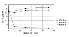
- the power of the excitation light was determined 10W, 30W, 50W, by calculating the output power and beam quality M 2 of the output light when changing the 70 W.
- the beam quality M 2 is the wavelength lambda, and divergence angle ⁇ of the output light, and is defined as the following formula by the beam diameter D.
- Example 1 the M 2 indicating the beam quality is lower than that in Comparative Example 1 at any pump light power, and it is shown that light with good beam quality is output. .
- Example 2 light with better beam quality was output. It should be noted that there was no difference in output power between Examples 1 and 2 and Comparative Example 1 at any pump light power.
- Example 3 Assuming an optical fiber for amplification similar to the optical fiber for amplification in Example 1, and in place of the single mode fiber in Example 1, the core diameter is 15 ⁇ m, the core ⁇ is 0.07%, A single mode fiber having an outer diameter of 125 ⁇ m was assumed. The ratio of the power of each mode in light propagating through such a single mode fiber is 89.8% for the LP01 mode, 9.8% for the LP02 mode, and 0.4% for the LP03 mode.
- Example 4 Assuming the same amplification optical fiber and the amplifying optical fiber of Example 2, further, in place of the single mode fiber in Example 2 was assumed the same single mode fiber and the single mode fiber of Example 3.
- Example 2 In the same manner as in Example 2, light was incident on the amplification optical fiber from the single mode fiber.
- the profiles of the LP01 mode, LP02 mode, and LP03 mode at this time were substantially the same as those in Example 3. Therefore, the intermediate region to which Yb was added included a region in which the intensity of the LP01 mode was stronger than that of the LP02 mode and the LP03 mode. Further, this amplification optical fiber satisfied the relationship of the above formulas 1 and 2.
- the intensity of light input from the single mode fiber of Examples 3 and 4 and Comparative Example 2 to the amplification optical fiber is set to 200 mW, and excitation light is input to the cladding of the amplification optical fiber.
- the output power and beam quality (M 2 ) of the output light when the power of the excitation light was changed to 10 W, 30 W, 50 W, and 70 W were obtained by calculation.
- Example 3 M 2 is a lower number indicating the beam quality than even Comparative Example 2 in the power of any excitation light, it was shown that the light of a good beam quality is output .
- Example 4 light with better beam quality was output. In any of the pumping light powers, there was no difference in output power between Examples 3 and 4 and Comparative Example 2.
- Example 5 Assuming an optical fiber for amplification similar to the optical fiber for amplification in Example 1, and instead of the single mode fiber in Example 1, the diameter of the core is 20 ⁇ m, the core ⁇ is 0.04%, A single mode fiber having an outer diameter of 125 ⁇ m was assumed. The ratio of the power of each mode in the light propagating through such a single mode fiber is 99.4% for the LP01 mode, 0.4% for the LP02 mode, and 0.2% for the LP03 mode.
- Example 6 An amplification optical fiber similar to the amplification optical fiber of Example 2 was assumed, and a single mode fiber similar to the single mode fiber of Example 5 was assumed instead of the single mode fiber of Example 2.
- Example 2 In the same manner as in Example 2, light was incident on the amplification optical fiber from the single mode fiber.
- the profiles of the LP01 mode, LP02 mode, and LP03 mode at this time were substantially the same as those in Example 5. Therefore, the intermediate region to which Yb was added included a region in which the intensity of the LP01 mode was stronger than that of the LP02 mode and the LP03 mode. Further, this amplification optical fiber satisfied the relationship of the above formulas 1 and 2.
- the power of light input from the single mode fiber of Examples 5 and 6 and Comparative Example 3 to the amplification optical fiber is set to 200 mW, and excitation light is input to the cladding of the amplification optical fiber.
- the output power and beam quality (M 2 ) of the output light when the power of the excitation light was changed to 10 W, 30 W, 50 W, and 70 W were obtained by calculation.
- Example 5 M 2 indicating the beam quality was lower than that in Comparative Example 3 at any pump light power, and it was shown that light with good beam quality was output. .
- Example 6 light with better beam quality was output. In any of the pumping light powers, there was no difference in output power between Examples 5 and 6 and Comparative Example 3.
- LP02 It was found that the beam quality of the output light can be improved because the amplification of the mode and the LP03 mode is suppressed and the LP01 mode is amplified with a high amplification factor. It was also found that the beam quality of the light can be further improved in the amplification optical fiber to which no active element is added at the outer peripheral portion.
- an optical fiber for amplification capable of outputting light of good beam quality even when a high-order mode is excited, and an optical fiber amplifier and a resonator using the optical fiber are provided. .
Abstract
Cette invention concerne une fibre optique d'amplification apte à émettre une lumière présentant un faisceau de bonne qualité et ce même en mode d'excitation de haut niveau. L'invention concerne en outre un amplificateur à fibre optique mettant en œuvre ladite fibre. Ladite fibre optique d'amplification (50) comprend comprises une âme (51) et une gaine (52) destinée à recouvrir l'âme (51). L'âme (51) propage une lumière d'une longueur d'onde prédéterminée en mode LP01 et/ou LP02 et/ou LP03. Un élément actif est ajouté au moins à une partie de la région de l'âme (51) dans laquelle l'intensité en mode LP01 est supérieure à l'intensité en mode LP02 et/ou en mode LP03 mode quand les modes LP01, LP02 et LP03 sont normalisés du point de vue de la puissance. L'ajout de l'élément actif est effectué à une concentration supérieure à celle de la partie centrale de l'âme.
Priority Applications (3)
| Application Number | Priority Date | Filing Date | Title |
|---|---|---|---|
| DK11837871.0T DK2642620T3 (da) | 2010-11-02 | 2011-10-18 | Forstærkende optisk fiber, optisk fiberforstærker og oscillator ved at anvende samme |
| CN201180052335.2A CN103262367B (zh) | 2010-11-02 | 2011-10-18 | 放大用光纤和使用了该光纤的光纤放大器以及谐振器 |
| EP11837871.0A EP2642620B1 (fr) | 2010-11-02 | 2011-10-18 | Fibre optique d'amplification, et amplificateur à fibre optique et oscillateur mettant en uvre ladite fibre |
Applications Claiming Priority (2)
| Application Number | Priority Date | Filing Date | Title |
|---|---|---|---|
| JP2010-246360 | 2010-11-02 | ||
| JP2010246360A JP4667535B1 (ja) | 2010-11-02 | 2010-11-02 | 増幅用光ファイバ、及び、それを用いた光ファイバ増幅器及び共振器 |
Publications (1)
| Publication Number | Publication Date |
|---|---|
| WO2012060220A1 true WO2012060220A1 (fr) | 2012-05-10 |
Family
ID=44021698
Family Applications (1)
| Application Number | Title | Priority Date | Filing Date |
|---|---|---|---|
| PCT/JP2011/073955 WO2012060220A1 (fr) | 2010-11-02 | 2011-10-18 | Fibre optique d'amplification, et amplificateur à fibre optique et oscillateur mettant en oeuvre ladite fibre |
Country Status (6)
| Country | Link |
|---|---|
| US (1) | US8456737B2 (fr) |
| EP (1) | EP2642620B1 (fr) |
| JP (1) | JP4667535B1 (fr) |
| CN (1) | CN103262367B (fr) |
| DK (1) | DK2642620T3 (fr) |
| WO (1) | WO2012060220A1 (fr) |
Cited By (1)
| Publication number | Priority date | Publication date | Assignee | Title |
|---|---|---|---|---|
| WO2022054287A1 (fr) * | 2020-09-14 | 2022-03-17 | 日本電信電話株式会社 | Fibre optique additionnée de terres rares et amplificateur de fibre optique |
Families Citing this family (20)
| Publication number | Priority date | Publication date | Assignee | Title |
|---|---|---|---|---|
| JP5124701B1 (ja) * | 2011-03-31 | 2013-01-23 | 株式会社フジクラ | 増幅用光ファイバ、及び、それを用いた光ファイバ増幅器及び共振器 |
| JP5727305B2 (ja) * | 2011-06-13 | 2015-06-03 | 日本電信電話株式会社 | 光ファイバ増幅器 |
| US8638493B2 (en) * | 2011-09-16 | 2014-01-28 | Alcatel Lucent | Optical system for signal amplification using a multimode fiber |
| JP5694266B2 (ja) * | 2012-10-02 | 2015-04-01 | 株式会社フジクラ | 光ファイバ及びそれを用いたファイバレーザ装置 |
| JP5771586B2 (ja) * | 2012-10-16 | 2015-09-02 | 株式会社フジクラ | 光ファイバ及びそれを用いたファイバレーザ装置 |
| JP6005472B2 (ja) * | 2012-10-24 | 2016-10-12 | 日本電信電話株式会社 | 光ファイバ |
| US9645310B2 (en) * | 2013-07-25 | 2017-05-09 | B.G. Negev Technologies And Applications Ltd. | Single large mode cladding amplification in active double-clad fibers |
| US10069271B2 (en) | 2014-06-02 | 2018-09-04 | Nlight, Inc. | Scalable high power fiber laser |
| JP6511235B2 (ja) * | 2014-09-01 | 2019-05-15 | 株式会社フジクラ | ファイバレーザ装置 |
| CN107924023B (zh) * | 2015-07-08 | 2020-12-01 | 恩耐公司 | 具有用于增加的光束参数乘积的中心折射率受抑制的纤维 |
| US11179807B2 (en) | 2015-11-23 | 2021-11-23 | Nlight, Inc. | Fine-scale temporal control for laser material processing |
| JP6268232B2 (ja) | 2016-07-04 | 2018-01-24 | 株式会社フジクラ | 光ファイバ、及び、レーザ装置 |
| CN109716184B (zh) * | 2016-07-20 | 2022-12-02 | 罗切斯特大学 | 用于抑制热模式不稳定性的lma光纤 |
| US10730785B2 (en) | 2016-09-29 | 2020-08-04 | Nlight, Inc. | Optical fiber bending mechanisms |
| EP3519871A1 (fr) | 2016-09-29 | 2019-08-07 | NLIGHT, Inc. | Caractéristiques réglables de faisceau |
| US10732439B2 (en) | 2016-09-29 | 2020-08-04 | Nlight, Inc. | Fiber-coupled device for varying beam characteristics |
| JP6668272B2 (ja) * | 2017-01-27 | 2020-03-18 | 株式会社フジクラ | 増幅用光ファイバ |
| KR102423330B1 (ko) * | 2017-04-21 | 2022-07-20 | 누부루 인크. | 다중-피복 광섬유 |
| US10969611B2 (en) * | 2017-07-14 | 2021-04-06 | The Government Of The United States Of America, As Represented By The Secretary Of The Navy | Devices for transmitting a modulated optical signal using a few-mode fiber |
| WO2020203900A1 (fr) * | 2019-03-29 | 2020-10-08 | 株式会社フジクラ | Fibre optique à élément actif, résonateur et dispositif laser à fibre |
Citations (6)
| Publication number | Priority date | Publication date | Assignee | Title |
|---|---|---|---|---|
| US5121460A (en) | 1991-01-31 | 1992-06-09 | The Charles Stark Draper Lab., Inc. | High-power mode-selective optical fiber laser |
| US5818630A (en) | 1997-06-25 | 1998-10-06 | Imra America, Inc. | Single-mode amplifiers and compressors based on multi-mode fibers |
| JP2003008114A (ja) * | 2001-06-25 | 2003-01-10 | Mitsubishi Cable Ind Ltd | 希土類元素ドープファイバ |
| WO2003067723A1 (fr) * | 2002-02-06 | 2003-08-14 | Mitsubishi Denki Kabushiki Kaisha | Fibre optique multimode, amplificateur laser a fibre, et oscillateur laser a fibre |
| JP2006128384A (ja) * | 2004-10-28 | 2006-05-18 | Hitachi Cable Ltd | ファイバレーザ用光ファイバ、ファイバレーザ及びレーザ発振方法 |
| JP2006516811A (ja) * | 2003-01-24 | 2006-07-06 | トルンプフ インコーポレイテッド | ファイバレーザ |
Family Cites Families (3)
| Publication number | Priority date | Publication date | Assignee | Title |
|---|---|---|---|---|
| US5966481A (en) * | 1997-12-23 | 1999-10-12 | Northern Telecom Limited | Optically pumped optical waveguide amplifier |
| US8068705B2 (en) * | 2009-09-14 | 2011-11-29 | Gapontsev Valentin P | Single-mode high-power fiber laser system |
| US8498044B2 (en) * | 2009-12-22 | 2013-07-30 | Fujikura Ltd. | Amplification optical fiber, and optical fiber amplifier and resonator using the same |
-
2010
- 2010-11-02 JP JP2010246360A patent/JP4667535B1/ja active Active
-
2011
- 2011-01-06 US US12/985,491 patent/US8456737B2/en active Active
- 2011-10-18 DK DK11837871.0T patent/DK2642620T3/da active
- 2011-10-18 EP EP11837871.0A patent/EP2642620B1/fr active Active
- 2011-10-18 CN CN201180052335.2A patent/CN103262367B/zh active Active
- 2011-10-18 WO PCT/JP2011/073955 patent/WO2012060220A1/fr active Application Filing
Patent Citations (6)
| Publication number | Priority date | Publication date | Assignee | Title |
|---|---|---|---|---|
| US5121460A (en) | 1991-01-31 | 1992-06-09 | The Charles Stark Draper Lab., Inc. | High-power mode-selective optical fiber laser |
| US5818630A (en) | 1997-06-25 | 1998-10-06 | Imra America, Inc. | Single-mode amplifiers and compressors based on multi-mode fibers |
| JP2003008114A (ja) * | 2001-06-25 | 2003-01-10 | Mitsubishi Cable Ind Ltd | 希土類元素ドープファイバ |
| WO2003067723A1 (fr) * | 2002-02-06 | 2003-08-14 | Mitsubishi Denki Kabushiki Kaisha | Fibre optique multimode, amplificateur laser a fibre, et oscillateur laser a fibre |
| JP2006516811A (ja) * | 2003-01-24 | 2006-07-06 | トルンプフ インコーポレイテッド | ファイバレーザ |
| JP2006128384A (ja) * | 2004-10-28 | 2006-05-18 | Hitachi Cable Ltd | ファイバレーザ用光ファイバ、ファイバレーザ及びレーザ発振方法 |
Non-Patent Citations (1)
| Title |
|---|
| RICHARD S. QUIMBY ET AL.: "Yb3+ Ring Doping in High-Order-Mode Fiberfor High-Power 977-nm Lasers and Amplifiers", IEEE JOURNAL OF SELECTED TOPICS IN QUANTUM ELECTRONICS, vol. 15, no. 1, January 2009 (2009-01-01), pages 12 - 19, XP055090261 * |
Cited By (1)
| Publication number | Priority date | Publication date | Assignee | Title |
|---|---|---|---|---|
| WO2022054287A1 (fr) * | 2020-09-14 | 2022-03-17 | 日本電信電話株式会社 | Fibre optique additionnée de terres rares et amplificateur de fibre optique |
Also Published As
| Publication number | Publication date |
|---|---|
| JP4667535B1 (ja) | 2011-04-13 |
| EP2642620A1 (fr) | 2013-09-25 |
| US8456737B2 (en) | 2013-06-04 |
| CN103262367A (zh) | 2013-08-21 |
| CN103262367B (zh) | 2015-03-18 |
| DK2642620T3 (da) | 2020-02-17 |
| EP2642620B1 (fr) | 2019-11-13 |
| US20120105947A1 (en) | 2012-05-03 |
| EP2642620A4 (fr) | 2018-02-07 |
| JP2012099649A (ja) | 2012-05-24 |
Similar Documents
| Publication | Publication Date | Title |
|---|---|---|
| JP4667535B1 (ja) | 増幅用光ファイバ、及び、それを用いた光ファイバ増幅器及び共振器 | |
| JP5159956B2 (ja) | 増幅用光ファイバ、及び、それを用いた光ファイバ増幅器及び共振器 | |
| JP5468666B2 (ja) | 増幅用光ファイバ、及び、それを用いた光ファイバ増幅器及び共振器 | |
| JP5779606B2 (ja) | 増幅用光ファイバ、及び、それを用いたファイバレーザ装置 | |
| JP5238509B2 (ja) | フォトニックバンドギャップファイバ | |
| JP5694266B2 (ja) | 光ファイバ及びそれを用いたファイバレーザ装置 | |
| WO2016035414A1 (fr) | Dispositif de laser à fibre | |
| JP5771586B2 (ja) | 光ファイバ及びそれを用いたファイバレーザ装置 | |
| JP5982307B2 (ja) | フォトニックバンドギャップファイバ、及び、それを用いたファイバレーザ装置 | |
| JP5643632B2 (ja) | マルチポートカプラ、及び、それを用いた光ファイバ増幅器及びファイバレーザ装置及び共振器 | |
| WO2016143713A1 (fr) | Fibre optique, amplificateur à fibre, et laser à fibre | |
| WO2019021565A1 (fr) | Dispositif laser à fibre |
Legal Events
| Date | Code | Title | Description |
|---|---|---|---|
| 121 | Ep: the epo has been informed by wipo that ep was designated in this application |
Ref document number: 11837871 Country of ref document: EP Kind code of ref document: A1 |
|
| NENP | Non-entry into the national phase |
Ref country code: DE |
|
| WWE | Wipo information: entry into national phase |
Ref document number: 2011837871 Country of ref document: EP |