WO2012060220A1 - Amplifying optical fiber, and optical fiber amplifier and oscillator using same - Google Patents
Amplifying optical fiber, and optical fiber amplifier and oscillator using same Download PDFInfo
- Publication number
- WO2012060220A1 WO2012060220A1 PCT/JP2011/073955 JP2011073955W WO2012060220A1 WO 2012060220 A1 WO2012060220 A1 WO 2012060220A1 JP 2011073955 W JP2011073955 W JP 2011073955W WO 2012060220 A1 WO2012060220 A1 WO 2012060220A1
- Authority
- WO
- WIPO (PCT)
- Prior art keywords
- mode
- optical fiber
- core
- light
- region
- Prior art date
Links
Images


Classifications
-
- H—ELECTRICITY
- H01—ELECTRIC ELEMENTS
- H01S—DEVICES USING THE PROCESS OF LIGHT AMPLIFICATION BY STIMULATED EMISSION OF RADIATION [LASER] TO AMPLIFY OR GENERATE LIGHT; DEVICES USING STIMULATED EMISSION OF ELECTROMAGNETIC RADIATION IN WAVE RANGES OTHER THAN OPTICAL
- H01S3/00—Lasers, i.e. devices using stimulated emission of electromagnetic radiation in the infrared, visible or ultraviolet wave range
- H01S3/05—Construction or shape of optical resonators; Accommodation of active medium therein; Shape of active medium
- H01S3/06—Construction or shape of active medium
- H01S3/063—Waveguide lasers, i.e. whereby the dimensions of the waveguide are of the order of the light wavelength
- H01S3/067—Fibre lasers
- H01S3/06708—Constructional details of the fibre, e.g. compositions, cross-section, shape or tapering
- H01S3/06729—Peculiar transverse fibre profile
- H01S3/06733—Fibre having more than one cladding
-
- G—PHYSICS
- G02—OPTICS
- G02B—OPTICAL ELEMENTS, SYSTEMS OR APPARATUS
- G02B6/00—Light guides; Structural details of arrangements comprising light guides and other optical elements, e.g. couplings
- G02B6/02—Optical fibres with cladding with or without a coating
- G02B6/036—Optical fibres with cladding with or without a coating core or cladding comprising multiple layers
- G02B6/03605—Highest refractive index not on central axis
- G02B6/03611—Highest index adjacent to central axis region, e.g. annular core, coaxial ring, centreline depression affecting waveguiding
-
- H—ELECTRICITY
- H01—ELECTRIC ELEMENTS
- H01S—DEVICES USING THE PROCESS OF LIGHT AMPLIFICATION BY STIMULATED EMISSION OF RADIATION [LASER] TO AMPLIFY OR GENERATE LIGHT; DEVICES USING STIMULATED EMISSION OF ELECTROMAGNETIC RADIATION IN WAVE RANGES OTHER THAN OPTICAL
- H01S3/00—Lasers, i.e. devices using stimulated emission of electromagnetic radiation in the infrared, visible or ultraviolet wave range
- H01S3/05—Construction or shape of optical resonators; Accommodation of active medium therein; Shape of active medium
- H01S3/06—Construction or shape of active medium
- H01S3/063—Waveguide lasers, i.e. whereby the dimensions of the waveguide are of the order of the light wavelength
- H01S3/067—Fibre lasers
- H01S3/06708—Constructional details of the fibre, e.g. compositions, cross-section, shape or tapering
- H01S3/0672—Non-uniform radial doping
-
- H—ELECTRICITY
- H01—ELECTRIC ELEMENTS
- H01S—DEVICES USING THE PROCESS OF LIGHT AMPLIFICATION BY STIMULATED EMISSION OF RADIATION [LASER] TO AMPLIFY OR GENERATE LIGHT; DEVICES USING STIMULATED EMISSION OF ELECTROMAGNETIC RADIATION IN WAVE RANGES OTHER THAN OPTICAL
- H01S3/00—Lasers, i.e. devices using stimulated emission of electromagnetic radiation in the infrared, visible or ultraviolet wave range
- H01S3/05—Construction or shape of optical resonators; Accommodation of active medium therein; Shape of active medium
- H01S3/08—Construction or shape of optical resonators or components thereof
- H01S3/08018—Mode suppression
- H01S3/0804—Transverse or lateral modes
-
- H—ELECTRICITY
- H01—ELECTRIC ELEMENTS
- H01S—DEVICES USING THE PROCESS OF LIGHT AMPLIFICATION BY STIMULATED EMISSION OF RADIATION [LASER] TO AMPLIFY OR GENERATE LIGHT; DEVICES USING STIMULATED EMISSION OF ELECTROMAGNETIC RADIATION IN WAVE RANGES OTHER THAN OPTICAL
- H01S3/00—Lasers, i.e. devices using stimulated emission of electromagnetic radiation in the infrared, visible or ultraviolet wave range
- H01S3/05—Construction or shape of optical resonators; Accommodation of active medium therein; Shape of active medium
- H01S3/06—Construction or shape of active medium
- H01S3/063—Waveguide lasers, i.e. whereby the dimensions of the waveguide are of the order of the light wavelength
- H01S3/067—Fibre lasers
- H01S3/0675—Resonators including a grating structure, e.g. distributed Bragg reflectors [DBR] or distributed feedback [DFB] fibre lasers
-
- H—ELECTRICITY
- H01—ELECTRIC ELEMENTS
- H01S—DEVICES USING THE PROCESS OF LIGHT AMPLIFICATION BY STIMULATED EMISSION OF RADIATION [LASER] TO AMPLIFY OR GENERATE LIGHT; DEVICES USING STIMULATED EMISSION OF ELECTROMAGNETIC RADIATION IN WAVE RANGES OTHER THAN OPTICAL
- H01S3/00—Lasers, i.e. devices using stimulated emission of electromagnetic radiation in the infrared, visible or ultraviolet wave range
- H01S3/09—Processes or apparatus for excitation, e.g. pumping
- H01S3/091—Processes or apparatus for excitation, e.g. pumping using optical pumping
- H01S3/094—Processes or apparatus for excitation, e.g. pumping using optical pumping by coherent light
- H01S3/094003—Processes or apparatus for excitation, e.g. pumping using optical pumping by coherent light the pumped medium being a fibre
-
- H—ELECTRICITY
- H01—ELECTRIC ELEMENTS
- H01S—DEVICES USING THE PROCESS OF LIGHT AMPLIFICATION BY STIMULATED EMISSION OF RADIATION [LASER] TO AMPLIFY OR GENERATE LIGHT; DEVICES USING STIMULATED EMISSION OF ELECTROMAGNETIC RADIATION IN WAVE RANGES OTHER THAN OPTICAL
- H01S3/00—Lasers, i.e. devices using stimulated emission of electromagnetic radiation in the infrared, visible or ultraviolet wave range
- H01S3/09—Processes or apparatus for excitation, e.g. pumping
- H01S3/091—Processes or apparatus for excitation, e.g. pumping using optical pumping
- H01S3/094—Processes or apparatus for excitation, e.g. pumping using optical pumping by coherent light
- H01S3/094069—Multi-mode pumping
-
- H—ELECTRICITY
- H01—ELECTRIC ELEMENTS
- H01S—DEVICES USING THE PROCESS OF LIGHT AMPLIFICATION BY STIMULATED EMISSION OF RADIATION [LASER] TO AMPLIFY OR GENERATE LIGHT; DEVICES USING STIMULATED EMISSION OF ELECTROMAGNETIC RADIATION IN WAVE RANGES OTHER THAN OPTICAL
- H01S3/00—Lasers, i.e. devices using stimulated emission of electromagnetic radiation in the infrared, visible or ultraviolet wave range
- H01S3/09—Processes or apparatus for excitation, e.g. pumping
- H01S3/091—Processes or apparatus for excitation, e.g. pumping using optical pumping
- H01S3/094—Processes or apparatus for excitation, e.g. pumping using optical pumping by coherent light
- H01S3/09408—Pump redundancy
-
- H—ELECTRICITY
- H01—ELECTRIC ELEMENTS
- H01S—DEVICES USING THE PROCESS OF LIGHT AMPLIFICATION BY STIMULATED EMISSION OF RADIATION [LASER] TO AMPLIFY OR GENERATE LIGHT; DEVICES USING STIMULATED EMISSION OF ELECTROMAGNETIC RADIATION IN WAVE RANGES OTHER THAN OPTICAL
- H01S3/00—Lasers, i.e. devices using stimulated emission of electromagnetic radiation in the infrared, visible or ultraviolet wave range
- H01S3/09—Processes or apparatus for excitation, e.g. pumping
- H01S3/091—Processes or apparatus for excitation, e.g. pumping using optical pumping
- H01S3/094—Processes or apparatus for excitation, e.g. pumping using optical pumping by coherent light
- H01S3/0941—Processes or apparatus for excitation, e.g. pumping using optical pumping by coherent light of a laser diode
- H01S3/09415—Processes or apparatus for excitation, e.g. pumping using optical pumping by coherent light of a laser diode the pumping beam being parallel to the lasing mode of the pumped medium, e.g. end-pumping
-
- H—ELECTRICITY
- H01—ELECTRIC ELEMENTS
- H01S—DEVICES USING THE PROCESS OF LIGHT AMPLIFICATION BY STIMULATED EMISSION OF RADIATION [LASER] TO AMPLIFY OR GENERATE LIGHT; DEVICES USING STIMULATED EMISSION OF ELECTROMAGNETIC RADIATION IN WAVE RANGES OTHER THAN OPTICAL
- H01S3/00—Lasers, i.e. devices using stimulated emission of electromagnetic radiation in the infrared, visible or ultraviolet wave range
- H01S3/14—Lasers, i.e. devices using stimulated emission of electromagnetic radiation in the infrared, visible or ultraviolet wave range characterised by the material used as the active medium
- H01S3/16—Solid materials
- H01S3/1601—Solid materials characterised by an active (lasing) ion
- H01S3/1603—Solid materials characterised by an active (lasing) ion rare earth
- H01S3/1618—Solid materials characterised by an active (lasing) ion rare earth ytterbium
Landscapes
- Physics & Mathematics (AREA)
- Electromagnetism (AREA)
- Optics & Photonics (AREA)
- Engineering & Computer Science (AREA)
- Plasma & Fusion (AREA)
- General Physics & Mathematics (AREA)
- Lasers (AREA)
- Optical Fibers, Optical Fiber Cores, And Optical Fiber Bundles (AREA)
Abstract
Provided is an amplifying optical fiber capable of outputting light having favorable beam quality even when a higher-order mode is excited. Also provided is an optical fiber amplifier using the fiber. The amplifying optical fiber (50) comprises a core (51) and a cladding (52) for covering the core (51). The core (51) propagates light of a predetermined wavelength in an LP01 mode and/or an LP02 mode and/or an LP03 mode. An active element is added to at least a part of the region of the core (51) where the intensity of the LP01 mode is higher than the intensity of the LP02 mode and/or the LP03 mode when the LP01, LP02, and LP03 modes are normalized relative to power, and the addition is made at a higher concentration than in the center part of the core.
Description
本発明は、増幅用光ファイバ、及び、それを用いた光ファイバ増幅器及び共振器に関し、特に、ビーム品質を向上することができる増幅用光ファイバ、及び、それを用いた光ファイバ増幅器及び共振器に関する。
The present invention relates to an optical fiber for amplification, and an optical fiber amplifier and resonator using the same, and more particularly, an optical fiber for amplification capable of improving beam quality, and an optical fiber amplifier and resonator using the same. About.
加工機や、医療機器等において使用されるファイバレーザ装置の一つとして、レーザ発振器(MO:Master Oscillator)等の種光源により発生される光を、増幅器(PA:Power Amplifier)で増幅して出力するMO-PA(Master Oscillator-Power Amplifier)型のファイバレーザ装置が知られている。この増幅器に用いられる増幅器の一つとして、増幅用光ファイバによって光を増幅する光ファイバ増幅器が知られている。
As one of fiber laser devices used in processing machines and medical equipment, the light generated by a seed light source such as a laser oscillator (MO: Master Oscillator) is amplified by an amplifier (PA: Power Amplifier) and output. An MO-PA (Master-Oscillator-Power Amplifier) type fiber laser device is known. As one of amplifiers used in this amplifier, an optical fiber amplifier that amplifies light by an amplification optical fiber is known.
この増幅用光ファイバにおいては、一般的にコアに希土類元素等の活性元素が添加されたダブルクラッドファイバが用いられている。このダブルクラッドファイバには、コアがシングルモード光のみを伝播するダブルクラッドファイバと、コアがマルチモード光を伝播するダブルクラッドファイバとがある。そして、コアがシングルモード光のみを伝播するダブルクラッドファイバにおいては、コアの断面積が小さいため、高出力のレーザ出力を得ようとするとコアを伝播する光の密度が高くなり過ぎる場合がある。この場合、非線形光学効果により光のエネルギーが所望でない波長に移行してしまい、期待したレーザ出力が得られないことがある。そこで、近年の光ファイバ増幅器の高出力化の要求に伴い、コアがマルチモード光を伝播するダブルクラッドファイバを用いた光ファイバ増幅器が注目されている。
In this optical fiber for amplification, a double clad fiber in which an active element such as a rare earth element is added to a core is generally used. This double clad fiber includes a double clad fiber whose core propagates only single mode light and a double clad fiber whose core propagates multimode light. In a double clad fiber in which the core propagates only single-mode light, since the cross-sectional area of the core is small, the density of light propagating through the core may become too high when trying to obtain a high-power laser output. In this case, the energy of light shifts to an undesired wavelength due to the nonlinear optical effect, and an expected laser output may not be obtained. Therefore, with the recent demand for higher output of optical fiber amplifiers, optical fiber amplifiers using a double clad fiber whose core propagates multimode light have attracted attention.
ところで、光ファイバ増幅器においては、伝播する光の内LP01モードが増幅され、他の高次モードが増幅されないことが、出力される光のビーム品質を向上させる観点から好ましい。下記特許文献には、このような光ファイバ増幅器の一例が記載されている。この光ファイバ増幅器においては、光のLP01モードのみを励振するようなモードコンバータを配することで、マルチモード光を伝播する増幅用ダブルクラッドファイバにおいてもLP01モードを中心に増幅できることが示されている。さらに、特許文献1においては、ダブルクラッドファイバのコアの中心部に活性元素が添加され、コアの外周部に活性元素が添加されていない増幅用光ファイバを用いることで、利得導波なる効果でLP01モードが高次モードに比べて効果的に増幅されることが示唆されている。
Incidentally, in the optical fiber amplifier, it is preferable from the viewpoint of improving the beam quality of the output light that the LP01 mode of the propagating light is amplified and the other higher-order modes are not amplified. The following patent document describes an example of such an optical fiber amplifier. In this optical fiber amplifier, it has been shown that, by arranging a mode converter that excites only the LP01 mode of light, even an amplifying double clad fiber that propagates multimode light can be amplified around the LP01 mode. . Furthermore, in Patent Document 1, an active optical element is added to the center of the core of the double-clad fiber, and an amplification optical fiber to which no active element is added is used at the outer periphery of the core. It has been suggested that the LP01 mode is more effectively amplified than the higher order modes.
また、特許文献2には、ダブルクラッドファイバのコアの中心部に活性元素が添加され、さらにコアの外周部に光を吸収する吸収元素が添加されている増幅用光ファイバを用いることで、不要な高次モードを減衰させるアイデアが記載されている。
Patent Document 2 does not require an amplification optical fiber in which an active element is added to the center of the core of a double clad fiber and an absorbing element that absorbs light is added to the outer periphery of the core. The idea of attenuating high-order modes is described.
しかし、光がマルチモード伝播できるダブルクラッドファイバを増幅用光ファイバとして用いると、伝播する光においてLP01モード(基本モード)以外に、LP02モード等の高次モードが励振されてしまう。このような高次モードの存在は、出力される光が集光されづらくなる等、出力される光のビーム品質を低下させてしまう。
However, when a double-clad fiber capable of multi-mode propagation of light is used as an amplification optical fiber, higher-order modes such as the LP02 mode are excited in addition to the LP01 mode (basic mode) in the propagating light. The presence of such a higher-order mode deteriorates the beam quality of the output light, for example, it becomes difficult to collect the output light.
また、特許文献1に記載されているモードコンバータを用いて、LP01モードのみを励振するためには、入力される種光のモードフィールドの形状と、増幅用ダブルクラッドファイバを伝播する光のLP01モードのモードフィールドの形状とを一致させる必要がある。本発明者らの知見によると、高次モードの中でも非対称モードであるLP11モードを励振させないことは比較的容易であるが、軸対称モードであるLP02モードやLP03モードは励振され易い。そして、LP02モードやLP03モード等の高次モードは、入力時において僅かなパワーである場合や、増幅用光ファイバ内で発生する場合においても、一般的にLP01モードよりも増幅される比率が高いため、出力する光において高い比率を占めてしまうことを本発明者らは見いだした。そして、光の増幅率が高い場合程、高次モードが増幅される比率が高くなり、出力する光のビーム品質が低下する傾向にあることが分かった。
In order to excite only the LP01 mode using the mode converter described in Patent Document 1, the shape of the mode field of the input seed light and the LP01 mode of light propagating through the amplifying double-clad fiber are used. It is necessary to match the shape of the mode field. According to the knowledge of the present inventors, it is relatively easy not to excite the LP11 mode, which is an asymmetric mode among higher order modes, but the LP02 mode and LP03 mode, which are axially symmetric modes, are easily excited. In addition, higher-order modes such as the LP02 mode and the LP03 mode generally have a higher amplification ratio than the LP01 mode, even when the power is small at the time of input or when it occurs in the amplification optical fiber. For this reason, the present inventors have found that the output light occupies a high ratio. It has been found that the higher the light amplification factor, the higher the higher-order mode amplification ratio and the lower the beam quality of the output light.
また、特許文献2に記載されているような光ファイバ増幅器を用いれば、軸対称の高次モードが励振される場合でも、そのモードが減衰することが予想されるが、増幅媒体に減衰物質を加えるために、LP01モードの利得も下がってしまい、十分な出力を得ることができないという問題がある。
Further, when an optical fiber amplifier as described in Patent Document 2 is used, even when an axially symmetric high-order mode is excited, it is expected that the mode will attenuate. In addition, the gain of the LP01 mode also decreases, and there is a problem that a sufficient output cannot be obtained.
そこで、本発明は、高次モードが励振された場合においても、良好なビーム品質の光を出力することができる増幅用光ファイバ、及び、それを用いた光ファイバ増幅器及び共振器を提供することを目的とする。
Therefore, the present invention provides an optical fiber for amplification that can output light of good beam quality even when a higher-order mode is excited, and an optical fiber amplifier and a resonator using the optical fiber. With the goal.
本発明者らは、LP01モード、及び、LP02モード、及び、LP03モードを含む光が、光ファイバのコアを伝播する場合、LP01モード、LP02モード、LP03モードが、コアの径方向においてどのように分布して増幅されるのかを鋭意検討した。その結果、LP02モード、LP03モードは、コアの中心部において、LP01モードよりも強度が強いということを見出した。従って、コアの径方向に対して均一に活性元素を添加したり、コアの中心部に活性元素を高い濃度で添加してしまうと、上記の様にLP02モードや、LP03モードが高い増幅率で増幅されてしまう。このため、出力光のビーム品質が悪くなってしまうという結論に至った。そこで本発明者らは、更に鋭意検討を重ねて本発明をするに至った。
When the light including the LP01 mode, the LP02 mode, and the LP03 mode propagates through the core of the optical fiber, the inventors of the present invention describe how the LP01 mode, the LP02 mode, and the LP03 mode are in the radial direction of the core. We sought to determine whether it was distributed and amplified. As a result, it has been found that the LP02 mode and the LP03 mode are stronger than the LP01 mode at the center of the core. Therefore, if the active element is uniformly added to the radial direction of the core or if the active element is added at a high concentration in the center of the core, the LP02 mode and the LP03 mode have a high amplification factor as described above. It will be amplified. For this reason, it came to the conclusion that the beam quality of output light will worsen. Therefore, the present inventors have made further investigations and made the present invention.
すなわち、本発明の増幅用光ファイバは、コアと、前記コアを被覆するクラッドとを有する増幅用光ファイバであって、前記コアは、所定の波長の光を少なくともLP01モード、及び、LP02モード、及び、LP03モードで伝播し、前記コアには、前記LP01モード及び前記LP02モード及び前記LP03モードをパワーで規格化する場合における、前記LP01モードの強度が、前記LP02モード及び前記LP03モードの少なくとも一方の強度よりも強い領域の少なくとも一部において、前記所定の波長の光を誘導放出する活性元素が、前記コアの中心部よりも高い濃度で添加され、下記式1及び式2の少なくとも一方を満たすことを特徴とするものである。

(ただし、rは、前記コアの径方向における中心からの距離であり、I01(r)は、前記LP01モードの前記コアの径方向における中心から距離rにおける強度であり、I02(r)は、前記LP02モードの前記コアの径方向における中心から距離rにおける強度であり、I03(r)は、前記LP03モードの前記コアの径方向における中心から距離rにおける強度であり、n(r)は、前記コアの径方向における中心から距離rにおける活性元素の添加濃度であり、bは前記コアの半径である。)
In other words, the amplifying optical fiber of the present invention, the core and provides a amplification optical fiber having a cladding covering the core, said core at least LP01 mode light having a predetermined wavelength, and, LP02 mode, And when the LP01 mode, the LP02 mode, and the LP03 mode are normalized by power, the strength of the LP01 mode is at least one of the LP02 mode and the LP03 mode. In at least a part of the region stronger than the intensity, the active element that stimulates and emits light of the predetermined wavelength is added at a higher concentration than the central portion of the core, and satisfies at least one of the following formulas 1 and 2 It is characterized by this.
(Where r is the distance from the center in the radial direction of the core, I 01 (r) is the strength at a distance r from the center in the radial direction of the core in the LP01 mode, and I 02 (r) is the is the intensity from the center at a distance r in the radial direction of the core of the LP02 mode, I 03 (r) is the intensity at a distance r from the center in the radial direction of the core of the LP03 mode, n (r ) Is the concentration of the active element added at a distance r from the center in the radial direction of the core, and b is the radius of the core.)
本発明においては、LP01モードがLP02モード及びLP03モードの少なくとも一方よりも強い領域において、活性元素がコアの中心部よりも高い濃度で添加される。この活性元素がコアの中心部よりも高い濃度で添加させる領域においては、光が、コアの中心部よりも高い増幅率で増幅される。このように、LP02モード及びLP03モードの強度がLP01モードの強度よりも強いコアの中心部よりも、LP01モードの強度がLP02モード及びLP03モードの少なくとも一方の強度よりも強い領域において、高い増幅率で光が増幅されることにより、少なくとも、LP02モード及びLP03モードの一方よりも、LP01モードを高い増幅率で増幅することができる。さらに、上記式1及び式2の少なくとも一方を満たすため、ファイバ全体としても、LP02モード及びLP03モードの一方よりも、LP01モードを高い増幅率で増幅することができるので、出力する光のビーム品質を良好にすることができる。
In the present invention, in a region where the LP01 mode is stronger than at least one of the LP02 mode and the LP03 mode, the active element is added at a higher concentration than the central portion of the core. In the region where the active element is added at a higher concentration than the central portion of the core, light is amplified at a higher amplification factor than the central portion of the core. Thus, in the region where the intensity of the LP01 mode is stronger than the intensity of at least one of the LP02 mode and the LP03 mode, compared with the central part of the core where the intensity of the LP02 mode and the LP03 mode is stronger than the intensity of the LP01 mode, By amplifying the light, the LP01 mode can be amplified with a higher amplification factor than at least one of the LP02 mode and the LP03 mode. Furthermore, since at least one of the above formulas 1 and 2 is satisfied, the LP01 mode can be amplified with a higher amplification factor than the LP02 mode and the LP03 mode as a whole fiber. Can be improved.
また、上記増幅用光ファイバにおいて、前記コアには、前記LP01モード及び前記LP02モード及び前記LP03モードをパワーで規格化する場合における、前記LP01モードの強度が、前記LP02モードの強度よりも強い領域の少なくとも一部、及び、前記LP01モードの強度が、前記LP03モードの強度よりも強い領域の少なくとも一部において、前記活性元素が、前記コアの中心部よりも高い濃度で添加され、前記式1及び前記式2の両方を満たすことが好ましい。
Further, in the amplification optical fiber, the core has a region where the strength of the LP01 mode is higher than the strength of the LP02 mode when the LP01 mode, the LP02 mode, and the LP03 mode are normalized by power. And the active element is added at a concentration higher than that of the central portion of the core in at least a part of a region where the intensity of the LP01 mode is higher than that of the LP03 mode, And it is preferable to satisfy both of the above-mentioned formula 2.
このような増幅用光ファイバにおいては、LP01モードの強度が、LP02モードの強度よりも強い領域において、LP01モードがLP02モードよりも高く増幅され、更に、LP01モードの強度が、LP03モードの強度よりも強い領域において、LP01モードがLP03モードよりも高く増幅される。そして、上記式1、及び、式2を満たすことにより、全体として、LP01モードがLP02モード及びLP03モードの両方よりも高い増幅率で増幅される。こうして、ビーム品質をより良好にすることができる。
In such an amplification optical fiber, the LP01 mode is amplified higher than the LP02 mode in a region where the LP01 mode is stronger than the LP02 mode, and the LP01 mode is stronger than the LP03 mode. In the stronger region, the LP01 mode is amplified higher than the LP03 mode. By satisfying Equation 1 and Equation 2, the LP01 mode as a whole is amplified with a higher amplification factor than both the LP02 mode and the LP03 mode. Thus, the beam quality can be improved.
さらに、上記増幅用光ファイバにおいて、前記コアには、前記LP01モード及び前記LP02モード及び前記LP03モードをパワーで規格化する場合における、前記LP01モードの強度が前記LP02モードの強度及び前記LP03モードの強度よりも強い領域の少なくとも一部において、前記活性元素が、前記コアの中心部よりも高い濃度で添加されていることが好ましい。
Further, in the amplification optical fiber, the LP01 mode intensity when the LP01 mode, the LP02 mode, and the LP03 mode are normalized by power is set to the intensity of the LP02 mode and the LP03 mode. In at least a part of the region stronger than the strength, the active element is preferably added at a higher concentration than the central portion of the core.
このような増幅用光ファイバによれば、LP01モードの強度が、LP02モード及びLP03モードの双方の強度よりも強い領域の少なくとも一部に活性元素を添加すれば良いため、LP01モードが、LP02モード及びLP03モードの双方よりも高い増幅率で増幅されるように、効率的に活性元素を添加することができる。
According to such an amplification optical fiber, it is only necessary to add an active element to at least a part of a region where the intensity of the LP01 mode is stronger than both the LP02 mode and the LP03 mode. The active element can be efficiently added so that the amplification factor is higher than that of both the LP03 mode and the LP03 mode.
さらに、上記増幅用光ファイバにおいて、前記コアには、前記LP01モード及び前記LP02モード及び前記LP03モードをパワーで規格化する場合における、前記LP01モードの強度が前記LP02モードの強度及び前記LP03モードの強度よりも強い領域の全てにおいて、前記活性元素が、前記コアの中心部よりも高い濃度で添加されていることが好ましい。
Further, in the optical fiber for amplification, the core includes, in the case where the LP01 mode, the LP02 mode, and the LP03 mode are normalized by power, the strength of the LP01 mode is the strength of the LP02 mode and the LP03 mode. It is preferable that the active element is added at a concentration higher than that of the central portion of the core in all regions stronger than the strength.
このような増幅用光ファイバによれば、ビーム品質を更に良好にすることができる。
According to such an amplification optical fiber, the beam quality can be further improved.
また、上記増幅用光ファイバにおいて、前記コアには、前記LP01モード及び前記LP02モード及び前記LP03モードをパワーで規格化する場合における、前記LP01モードの強度が、前記LP02モード及び前記LP03モードの少なくとも一方の強度よりも強い領域の全てにおいて、前記活性元素が、前記コアの中心部よりも高い濃度で添加され、前記式1及び前記式2の両方を満たすことが好ましい。
Further, in the amplification optical fiber, the core has an intensity of the LP01 mode when the LP01 mode, the LP02 mode, and the LP03 mode are normalized with power, at least of the LP02 mode and the LP03 mode. In all the regions stronger than one strength, it is preferable that the active element is added at a concentration higher than that of the central portion of the core and satisfy both the formula 1 and the formula 2.
このような光ファイバによれば、LP01モードの強度が、LP02モード及びLP03モードの少なくとも一方よりも強い領域の全てにおいて、LP01モードがより高い増幅率で増幅される。従って、出力する光のビーム品質をより良好にすることができる。
According to such an optical fiber, the LP01 mode is amplified with a higher amplification factor in the entire region where the intensity of the LP01 mode is stronger than at least one of the LP02 mode and the LP03 mode. Therefore, the beam quality of the output light can be improved.
また、上記増幅用光ファイバにおいて、前記コアの前記中心部には、前記活性元素が添加されていないことが好ましい。
In the amplification optical fiber, it is preferable that the active element is not added to the central portion of the core.
このような増幅用光ファイバによれば、LP02モードやLP03モードの強度がLP01モードの強度よりも強いコアの中心部において、光が増幅されないため、出力する光のビーム品質をより良好にすることができる。
According to such an optical fiber for amplification, since light is not amplified in the central portion of the core where the intensity of the LP02 mode or LP03 mode is higher than that of the LP01 mode, the beam quality of the output light can be improved. Can do.
また、上記増幅用光ファイバにおいて、前記コアの外周部においては、前記コアの中心部よりも活性元素が高い濃度で添加される領域よりも、前記活性元素の濃度が低くされていることが好ましい。
In the amplification optical fiber, it is preferable that the concentration of the active element is lower in the outer peripheral portion of the core than in a region where the active element is added at a higher concentration than the central portion of the core. .
本発明者らは、上記検討において、LP02モード、及び、LP03モードは、コアの外周部において、LP01モードよりも強度が強いということを更に見出した。従って、このような増幅用光ファイバによれば、LP01モードの強度よりもLP02モード及びLP03モードの強度が強い外周部において、LP02モード、及び、LP03モードの増幅率をLP01モードの増幅率よりも低く抑えることができるため、出力する光のビーム品質をより良好にすることができる。
In the above examination, the present inventors have further found that the LP02 mode and the LP03 mode are stronger than the LP01 mode in the outer peripheral portion of the core. Therefore, according to such an optical fiber for amplification, the amplification factor of the LP02 mode and the LP03 mode is higher than the amplification factor of the LP01 mode in the outer peripheral portion where the strength of the LP02 mode and the LP03 mode is stronger than that of the LP01 mode. Since it can be kept low, the beam quality of the output light can be made better.
さらに、上記増幅用光ファイバにおいて、前記コアの前記外周部には、活性元素が添加されていないことが好ましい。
Furthermore, in the amplification optical fiber, it is preferable that no active element is added to the outer peripheral portion of the core.
このような増幅用光ファイバによれば、出力する光のビーム品質を更に良好にすることができる。
According to such an amplification optical fiber, the beam quality of the output light can be further improved.
また、上記増幅用光ファイバにおいて、前記コアを挟む一対の応力付与部が、前記クラッド内に設けられることが好ましい。
In the amplification optical fiber, it is preferable that a pair of stress applying portions sandwiching the core is provided in the clad.
このような応力付与部を設けることにより、コアを伝播する光を単一偏波とすることができる。
By providing such a stress applying portion, the light propagating through the core can be made into a single polarization.
また、本発明の光ファイバ増幅器は、上記の増幅用光ファイバと、LP01モードを含む種光を前記増幅用光ファイバに入力させる種光源と、前記増幅用光ファイバの前記活性元素を励起する励起光を出力する励起光源と、を備えることを特徴とするものである。
The optical fiber amplifier according to the present invention includes the amplification optical fiber, a seed light source for inputting seed light including an LP01 mode to the amplification optical fiber, and excitation for exciting the active element of the amplification optical fiber. And an excitation light source that outputs light.
このような光ファイバ増幅器によれば、LP02モードや、LP03モードが励振される場合においても、LP01モードをより高い増幅率で増幅するため、良好なビーム品質の光を出力することができる。
According to such an optical fiber amplifier, even when the LP02 mode or the LP03 mode is excited, the LP01 mode is amplified with a higher amplification factor, so that light with good beam quality can be output.
さらに、上記光ファイバ増幅器において、前記増幅用光ファイバに入力する種光は、前記増幅用光ファイバの軸対称のモードのみを励振することが好ましい。
Furthermore, in the optical fiber amplifier, it is preferable that the seed light input to the amplification optical fiber excites only an axially symmetric mode of the amplification optical fiber.
このような光ファイバ増幅器によれば、増幅用光ファイバにおいて、非軸対称の高次モードが伝播しないため、非軸対称の高次モードが増幅されて出力することがないので、集光が行いやすい良好なビーム品質の光を出力することができる。
According to such an optical fiber amplifier, since the non-axisymmetric higher-order mode does not propagate in the amplification optical fiber, the non-axisymmetric higher-order mode is not amplified and output. Easy to output light with good beam quality.
また、上記光ファイバ増幅器において、前記増幅用光ファイバに入力する種光は、シングルモード光であることが好ましい。
In the optical fiber amplifier, the seed light input to the amplification optical fiber is preferably single mode light.
このような光ファイバ増幅器によれば、マルチモード光を伝播する増幅用光ファイバにおいて、非軸対称の高次モードや高次モードの光が励振しにくいため、集光が行いやすい良好なビーム品質の光を出力することができる。
According to such an optical fiber amplifier, it is difficult to excite non-axisymmetric high-order mode or high-order mode light in an amplification optical fiber that propagates multi-mode light, so that good beam quality is easily obtained. Can be output.
また、本発明の共振器は、上記に記載の増幅用光ファイバと、前記増幅用光ファイバの前記活性元素を励起する励起光を出力する励起光源と、前記増幅用光ファイバの一方側に設けられ、前記励起光により励起された前記活性元素が放出する光の少なくとも一部の波長の光を反射する第1FBG(Fiber Bragg Grating)と、前記増幅用光ファイバの他方側に設けられ、前記第1FBGが反射する光と同じ波長の光を前記第1FBGよりも低い反射率で反射する第2FBGと、を備えることを特徴とするものである。
A resonator according to the present invention is provided on the one side of the amplification optical fiber, an excitation light source that outputs excitation light for exciting the active element of the amplification optical fiber, and the amplification optical fiber. A first FBG (Fiber Bragg Grating) that reflects light of at least a part of the light emitted by the active element excited by the excitation light, and provided on the other side of the amplification optical fiber, And a second FBG that reflects light having the same wavelength as the light reflected by the 1FBG with a reflectance lower than that of the first FBG.
このような共振器によれば、光の共振において、増幅用光ファイバのコアを光が伝播するときに、LP01モードがLP02モード及びLP03モードより強く増幅されるので、活性元素の濃度がコアに均一に添加されたファイバを用いる場合と比較して、LP02モード及びLP03モードの強度に対するLP01モードの強度が強い、良好なビーム品質の光を出力することができる。
According to such a resonator, in light resonance, when light propagates through the core of the amplification optical fiber, the LP01 mode is amplified more strongly than the LP02 mode and the LP03 mode. Compared with the case of using a uniformly added fiber, it is possible to output light with a good beam quality, in which the intensity of the LP01 mode is higher than the intensity of the LP02 mode and the LP03 mode.
以上のように、本発明によれば、高次モードが励振された場合においても、良好なビーム品質の光を出力することができる増幅用光ファイバ、及び、それを用いた光ファイバ増幅器及び共振器が提供される。
As described above, according to the present invention, an optical fiber for amplification capable of outputting light of good beam quality even when a higher mode is excited, an optical fiber amplifier using the optical fiber, and a resonance A vessel is provided.
以下、本発明に係る増幅用光ファイバ、及び、光ファイバ増幅器及び共振器の好適な実施形態について図面を参照しながら詳細に説明する。
Hereinafter, preferred embodiments of an amplification optical fiber, an optical fiber amplifier, and a resonator according to the present invention will be described in detail with reference to the drawings.
(第1実施形態)
図1は、本発明の第1実施形態に係る光ファイバ増幅器を示す図である。 (First embodiment)
FIG. 1 is a diagram showing an optical fiber amplifier according to a first embodiment of the present invention.
図1は、本発明の第1実施形態に係る光ファイバ増幅器を示す図である。 (First embodiment)
FIG. 1 is a diagram showing an optical fiber amplifier according to a first embodiment of the present invention.
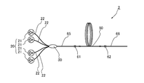
図1に示すように、本実施形態における光ファイバ増幅器1は、種光となる光を出力する種光源10と、励起光を出力する励起光源20と、種光及び励起光が入力する光コンバイナ30と、光コンバイナ30から出力される種光及び励起光が入力し、励起光により励起される活性元素が添加された増幅用光ファイバ50とを主な構成として備える。
As shown in FIG. 1, an optical fiber amplifier 1 according to this embodiment includes a seed light source 10 that outputs light serving as seed light, a pump light source 20 that outputs pump light, and an optical combiner that receives seed light and pump light. 30 and the amplification optical fiber 50 to which the seed light and the pumping light output from the optical combiner 30 are input and the active element excited by the pumping light is added.
種光源10は、例えば、半導体レーザ装置や、ファブリペロー型やファイバリング型のファイバレーザ装置から構成されている。この種光源10は、LP01モードを含む光を光ファイバから出力するように構成されている。また、種光源10から出力される種光は、LP01モードを含む光である限りにおいて、特に制限されるものではないが、波長は、増幅用光ファイバ50に添加される活性元素が誘導放出できる波長であり、例えば、活性元素をイッテルビウム(Yb)とした場合には、波長が1070nmのレーザ光とされる。
The seed light source 10 includes, for example, a semiconductor laser device, a Fabry-Perot type, or a fiber ring type fiber laser device. The seed light source 10 is configured to output light including an LP01 mode from an optical fiber. Further, the seed light output from the seed light source 10 is not particularly limited as long as it is light including the LP01 mode, but the wavelength can stimulate and emit the active element added to the amplification optical fiber 50. For example, when the active element is ytterbium (Yb), the wavelength is 1070 nm.
また、種光源10の出力光は、コア、及び、コアを被覆するクラッドから構成されるシングルモードファイバ15から出力される。このシングルモードファイバ15は、種光源10から出力される光を、LP01モードのシングルモード光として伝播する。このシングルモードファイバ15の構成は特に制限されるものではないが、例えば、種光の波長が上記のように1070nmである場合には、コアの直径が10μmとされ、コアとクラッドとの比屈折率差が0.13%とされる。
Also, the output light of the seed light source 10 is output from the single mode fiber 15 composed of the core and the clad covering the core. The single mode fiber 15 propagates light output from the seed light source 10 as LP01 mode single mode light. The configuration of the single mode fiber 15 is not particularly limited. For example, when the wavelength of the seed light is 1070 nm as described above, the core diameter is 10 μm, and the relative refraction between the core and the clad is made. The rate difference is 0.13%.
励起光源20は、複数のレーザダイオード21から構成され、レーザダイオード21は、本実施形態においては、例えば、GaAs系半導体を材料としたファブリペロー型半導体レーザであり、中心波長が915nmの光を出力する。また、励起光源20のそれぞれのレーザダイオード21は、マルチモードファイバ22に接続されており、レーザダイオード21から出力される励起光は、マルチモードファイバ22をマルチモード光として伝播する。
The excitation light source 20 is composed of a plurality of laser diodes 21. In the present embodiment, the laser diode 21 is a Fabry-Perot type semiconductor laser made of a GaAs-based semiconductor, for example, and outputs light having a center wavelength of 915 nm. To do. Each laser diode 21 of the excitation light source 20 is connected to the multimode fiber 22, and the excitation light output from the laser diode 21 propagates through the multimode fiber 22 as multimode light.
マルチモードファイバ22及びシングルモードファイバ15が接続される光コンバイナ30は、シングルモードファイバ15を中心としてその周りにマルチモードファイバを配置した部分が溶融延伸されて一体化することにより構成されており、増幅用光ファイバ50に光学的に接続されている。
The optical combiner 30 to which the multimode fiber 22 and the single mode fiber 15 are connected is configured by melting and extending a portion where the multimode fiber is disposed around the single mode fiber 15 as a center, The optical fiber 50 is optically connected to the amplification optical fiber 50.
図2は、増幅用光ファイバ50の長手方向に垂直な断面における構造を示す図である。図2に示すように増幅用光ファイバ50は、コア51と、コア51を被覆するクラッド52と、クラッド52を被覆する外部クラッド53とから構成される。クラッド52の屈折率はコア51の屈折率よりも低く、外部クラッド53の屈折率はクラッド52の屈折率よりも低くされる。例えば、本実施形態において、コア51とクラッド52との比屈折率差は、0.32%とされる。また、コア51の直径は、例えば30μmとされ、クラッド52の外径は、例えば420μmとされ、外部クラッド53の外径は、例えば440μmとされる。また、コア51を構成する材料としては、例えば、石英の屈折率を上昇させるアルミニウム等の元素が添加される石英が挙げられ、コア51の少なくとも一部の領域には、励起光源20から出力される励起光により励起状態とされる活性元素であるイッテルビウム(Yb)が添加される。なお、このような活性元素としては、イッテルビウム(Yb)の他に、例えばネオジウム(Nd)やエルビウム(Er)等の希土類元素を挙げることができる。さらに活性元素として、希土類元素の他に、ビスマス(Bi)やクロム(Cr)等が挙げられる。また、クラッド52を構成する材料としては、例えば、ドーパントが添加されない石英が挙げられ、外部クラッド53を構成する材料としては、例えば、紫外線硬化樹脂が挙げられる。
FIG. 2 is a diagram showing a structure in a cross section perpendicular to the longitudinal direction of the amplification optical fiber 50. As shown in FIG. 2, the amplification optical fiber 50 includes a core 51, a clad 52 that covers the core 51, and an outer clad 53 that covers the clad 52. The refractive index of the cladding 52 is lower than the refractive index of the core 51, and the refractive index of the outer cladding 53 is lower than the refractive index of the cladding 52. For example, in this embodiment, the relative refractive index difference between the core 51 and the clad 52 is 0.32%. The core 51 has a diameter of, for example, 30 μm, the cladding 52 has an outer diameter of, for example, 420 μm, and the outer cladding 53 has an outer diameter of, for example, 440 μm. The material constituting the core 51 includes, for example, quartz to which an element such as aluminum that increases the refractive index of quartz is added, and is output from the excitation light source 20 to at least a partial region of the core 51. Ytterbium (Yb) which is an active element that is excited by the excitation light is added. In addition to ytterbium (Yb), examples of such active elements include rare earth elements such as neodymium (Nd) and erbium (Er). In addition to rare earth elements, active elements include bismuth (Bi), chromium (Cr), and the like. The material constituting the clad 52 includes, for example, quartz to which no dopant is added, and the material constituting the outer clad 53 includes, for example, an ultraviolet curable resin.
上記のようなコア51とクラッド52との屈折率差により、コア51には種光源からの所定の波長の光が閉じ込められて伝播する。このコア51を伝播する光のモードとしては、基本モードであるLP01モードの他に、高次のモードとして、LP02モードやLP03モードが存在する。本実施形態に係る増幅用光ファイバ50においては、LP04以上の高次モードは伝播しないように、種光源の光の波長、コア51並びにクラッド52の寸法、及びコア51とクラッド52との比屈折率差を設定している。このようにLP04モード以上の高次モードが伝播されないように設定するには、例えば、上述のように、種光の波長が1070nmであり、コア51の直径が30μmで、コア51とクラッド52との比屈折率差が0.32%となるようにすれば良い。
Due to the difference in refractive index between the core 51 and the clad 52 as described above, light having a predetermined wavelength from the seed light source is confined and propagated in the core 51. As modes of light propagating through the core 51, in addition to the LP01 mode, which is a basic mode, LP02 mode and LP03 mode exist as higher-order modes. In the amplification optical fiber 50 according to the present embodiment, the wavelength of the seed light, the dimensions of the core 51 and the clad 52, and the relative refraction of the core 51 and the clad 52 are prevented so that higher-order modes higher than LP04 do not propagate. The rate difference is set. In this way, in order to set so that the higher-order mode higher than the LP04 mode is not propagated, for example, as described above, the wavelength of the seed light is 1070 nm, the diameter of the core 51 is 30 μm, the core 51 and the cladding 52 The relative refractive index difference may be 0.32%.
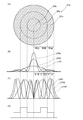
次に増幅用光ファイバ50のコア51について、さらに詳しく説明する。図3は、図2に示す増幅用光ファイバ50のコア51の様子を示す図である。具体的には、図3のAは、増幅用光ファイバ50の長手方向に対して垂直な断面におけるコア51の構造を示す図である。また、図3のBは、コア51を伝播するLP01モード及びLP02モード及びLP03モードにおける規格化した単位面積当たりの強度の分布を示す図である。また、図3のCは、コア51を伝播するLP01モード及びLP02モード及びLP03モードの強度を面積で積分し、規格化したパワーの分布を示す図である。また、図3のDは、コア51に添加されている活性元素の濃度分布の様子を示す図である。
Next, the core 51 of the amplification optical fiber 50 will be described in more detail. FIG. 3 is a diagram showing a state of the core 51 of the amplification optical fiber 50 shown in FIG. Specifically, FIG. 3A shows the structure of the core 51 in a cross section perpendicular to the longitudinal direction of the amplification optical fiber 50. FIG. 3B is a diagram showing the distribution of intensity per unit area normalized in the LP01 mode, the LP02 mode, and the LP03 mode propagating through the core 51. FIG. 3C is a diagram showing a normalized power distribution obtained by integrating the intensity of the LP01 mode, the LP02 mode, and the LP03 mode propagating through the core 51 by the area. 3D is a diagram showing a state of concentration distribution of the active element added to the core 51. FIG.
図3のBに示すように、それぞれのモードは、コア51の中心で最も強くなる強度分布を有している。この中心における強度は、LP03モードが最も大きく、次いでLP02モードであり、LP01モードの強度が最も小さい。そして、コア51の中心から径方向に離れると、LP01モードの強度が、LP03モードの強度よりも大きくなる。ここで、図3に示すように、コア51の中心から、LP01モードの強度が、LP03モードの強度よりも大きくなるまでの径方向における領域を領域Aとする。更にコア51の中心から径方向に離れると、LP01モードの強度が、LP02モード及びLP03モードの強度よりも大きくなる。ここで、領域Aの外周側でLP01モードの強度が、LP02モード及びLP03モードの強度よりも大きくなるまでの領域を領域Bとする。そして、更にコア51の中心から径方向に離れると、一時的にLP03モードの強度がLP01モードの強度よりも大きくなる。ここで、領域Bの外周側で、一時的にLP03モードの強度がLP01モードの強度よりも大きくなるまでの領域を領域Cとして、一時的にLP03モードの強度がLP01モードの強度よりも大きくなっている領域を領域Dとする。そして、更にコア51の中心から径方向に離れると、領域Dの外周側において、LP01モードの強度が、LP02モード及びLP03モードの強度よりも大きくなっている。この領域Dの外周側で、LP01モードの強度が、LP02モード及びLP03モードの強度よりも大きくなっている領域を領域Eとする。更に領域Eの外周側において、LP02モードの強度がLP01モードの強度よりも大きくなり、更に、外周側においては、LP01モードの強度は、LP02モード及びLP03モードの強度よりも小さくなる。この領域Eの外周側で、LP01モードの強度が、LP02モード及びLP03モードの強度よりも小さくなるまでの領域を領域Fとし、領域Fの外周側の領域を領域Gとする。
As shown in FIG. 3B, each mode has an intensity distribution that is strongest at the center of the core 51. The intensity at this center is the largest in the LP03 mode, followed by the LP02 mode, and the intensity in the LP01 mode is the smallest. And when it leaves | separates from the center of the core 51 to radial direction, the intensity | strength of LP01 mode will become larger than the intensity | strength of LP03 mode. Here, as shown in FIG. 3, a region in the radial direction from the center of the core 51 until the strength of the LP01 mode becomes larger than the strength of the LP03 mode is defined as a region A. Furthermore, when it leaves | separates from the center of the core 51 to radial direction, the intensity | strength of LP01 mode will become larger than the intensity | strength of LP02 mode and LP03 mode. Here, a region where the intensity of the LP01 mode on the outer peripheral side of the region A becomes larger than the strengths of the LP02 mode and the LP03 mode is defined as a region B. When further away from the center of the core 51 in the radial direction, the intensity of the LP03 mode temporarily becomes larger than the intensity of the LP01 mode. Here, on the outer periphery side of the region B, a region until the strength of the LP03 mode temporarily becomes larger than the strength of the LP01 mode is defined as a region C, and the strength of the LP03 mode is temporarily larger than the strength of the LP01 mode. The area that is in question is area D. Further, further away from the center of the core 51 in the radial direction, on the outer peripheral side of the region D, the strength of the LP01 mode is higher than the strength of the LP02 mode and the LP03 mode. A region where the intensity of the LP01 mode is larger than the strength of the LP02 mode and the LP03 mode on the outer periphery side of the region D is defined as a region E. Further, on the outer peripheral side of the region E, the strength of the LP02 mode is larger than the strength of the LP01 mode, and further, on the outer peripheral side, the strength of the LP01 mode is smaller than the strength of the LP02 mode and the LP03 mode. A region where the intensity of the LP01 mode becomes smaller than the strength of the LP02 mode and the LP03 mode on the outer periphery side of the region E is defined as a region F, and a region on the outer periphery side of the region F is defined as a region G.
このようにそれぞれの領域を定義する場合に、領域Aは、コア51の長さ方向に垂直な断面における形状が、円形となり、他の領域B~Gは、それぞれリング状に分布する。そして、コア51の直径が、例えば、上述のように、30μmである場合に、中心から領域Aと領域Bとの境界までの距離は、約3μmであり、中心から領域Bと領域Cとの境界までの距離は、約4μmであり、中心から領域Cと領域Dとの境界までの距離は、約7μmであり、中心から領域Dと領域Eとの境界までの距離は、約8.5μmであり、中心から領域Eと領域Fとの境界までの距離は、約10μmであり、中心から領域Fと領域Gとの境界までの距離は、約12μmとなる。
When each region is defined as described above, the region A has a circular shape in a cross section perpendicular to the length direction of the core 51, and the other regions B to G are distributed in a ring shape. For example, when the diameter of the core 51 is 30 μm as described above, the distance from the center to the boundary between the region A and the region B is about 3 μm, and the distance between the center and the region B and the region C is The distance to the boundary is about 4 μm, the distance from the center to the boundary between the region C and the region D is about 7 μm, and the distance from the center to the boundary between the region D and the region E is about 8.5 μm. The distance from the center to the boundary between the region E and the region F is about 10 μm, and the distance from the center to the boundary between the region F and the region G is about 12 μm.
そして、領域A、及び、領域Gにおいては、LP01モードの強度は、LP02モード及びLP03モードの強度よりも小さくなる。そして、領域B、領域C、領域Fにおいては、LP01モードの強度が、LP02モード及びLP03モードの強度の一方よりも大きくなる。そして、領域C及び領域Eにおいては、LP01モードの強度が、LP02モード及びLP03モードよりも大きくなる。
And in the region A and the region G, the intensity of the LP01 mode is smaller than the intensity of the LP02 mode and the LP03 mode. In regions B, C, and F, the LP01 mode intensity is greater than one of the LP02 mode and LP03 mode intensity. In the region C and the region E, the intensity of the LP01 mode is larger than that of the LP02 mode and the LP03 mode.
このようなLP01モード、LP02モード、LP03モードの強度の関係は、図3のCに示す分布においても同様となる。
The relationship between the LP01 mode, LP02 mode, and LP03 mode intensities is the same in the distribution shown in FIG.
そして、コア51には、LP01モード及びLP02モード及びLP03モードをパワーで規格化する場合における、LP01モードの強度が、LP02モード及びLP03モードの少なくとも一方の強度よりも強い領域の少なくとも一部において、活性元素が、コアの中心部よりも高い濃度で添加されている。つまり、上記領域のB~Fの少なくとも一部のリング状の領域において、活性元素の一つであるYbがコア51の中心部よりも高い濃度で添加されている。
In the core 51, in the case where the LP01 mode, the LP02 mode, and the LP03 mode are normalized by power, the strength of the LP01 mode is at least partly higher than the strength of at least one of the LP02 mode and the LP03 mode. The active element is added at a higher concentration than the central part of the core. That is, Yb, which is one of the active elements, is added at a concentration higher than that of the central portion of the core 51 in at least a part of the ring-shaped regions B to F in the region.
更に、この活性元素の添加は、下記式1及び式2のいずれも満たすように添加されている。

Further, the addition of this active element is performed so as to satisfy both of the following formulas 1 and 2.
ただし、rは、コア51の径方向における中心からの距離であり、I01(r)は、図3のBに示すLP01モードのコア51の径方向における中心から距離rにおける強度であり、I02(r)は、図3のBに示すLP02モードのコア51の径方向における中心から距離rにおける強度であり、I03(r)は、図3のBに示すLP03モードのコア51の径方向における中心から距離rにおける強度であり、n(r)は、コア51の径方向における中心から距離rにおける活性元素の添加濃度であり、bはコア51の半径である。なお、rの単位は、(m)であり、I01(r)、I02(r)I03(r)の単位は、(W/m2)であり、n(r)の単位は、(個/m3)であり、bの単位は、(m)である。
However, r is the distance from the center in the radial direction of the core 51, I 01 (r) is the intensity at the distance r from the center in the radial direction of the core 51 of the LP01 mode shown in FIG. 02 (r) is the intensity at a distance r from the center in the radial direction of the LP02 mode of the core 51 shown in B of FIG. 3, I 03 (r), the diameter of the LP03 mode of the core 51 shown in B of FIG. 3 The intensity at a distance r from the center in the direction, n (r) is the additive concentration of the active element at the distance r from the center in the radial direction of the core 51, and b is the radius of the core 51. The unit of r is (m), the unit of I 01 (r), I 02 (r) I 03 (r) is (W / m 2 ), and the unit of n (r) is (Pieces / m 3 ), and the unit of b is (m).
そして、本実施形態においては、図3のAに示すように、コア51中心を含む中心領域55に活性元素Ybを8×1025(個/m3)添加し、この中心領域55の外側の外周領域57に活性元素Ybを16×1025(個/m3)添加している。この中心領域55と外周領域57との境界は、領域Cに含まれる。
In the present embodiment, as shown in FIG. 3A, 8 × 10 25 (pieces / m 3 ) of the active element Yb is added to the central region 55 including the center of the core 51, and the outside of the central region 55 is added. 16 × 10 25 (pieces / m 3 ) of the active element Yb is added to the outer peripheral region 57. The boundary between the central region 55 and the outer peripheral region 57 is included in the region C.
すなわち、LP01モード及びLP02モード及びLP03モードをパワーで規格化する場合における、LP01モードの強度が、LP02モード及びLP03モードの強度よりも強い領域である領域C及び領域Eにおける活性元素Ybの添加濃度は、活性コアの中心部の中心領域55における活性元素Ybの添加濃度より高い。
That is, when the LP01 mode, the LP02 mode, and the LP03 mode are normalized by power, the addition concentration of the active element Yb in the region C and the region E in which the intensity of the LP01 mode is stronger than the intensity of the LP02 mode and the LP03 mode Is higher than the additive concentration of the active element Yb in the central region 55 at the center of the active core.
また、この中心領域55における活性元素Ybの添加濃度と外周領域57における活性元素Yb添加濃度は、式1及び式2の関係を満たすように設定されている。すなわち、コア51内の活性元素の添加濃度分布は、式1及び式2の関係を満たすものであれば、LP02モード及びLP03モードよりも、LP01モードを高い増幅率で増幅することができ、出力する光のビーム品質を良好にすることができる。
Further, the additive concentration of the active element Yb in the central region 55 and the additive concentration of the active element Yb in the outer peripheral region 57 are set so as to satisfy the relationship of the equations 1 and 2. That is, as long as the concentration distribution of the active element in the core 51 satisfies the relationship of Equation 1 and Equation 2, the LP01 mode can be amplified with a higher amplification factor than the LP02 mode and LP03 mode, and the output The beam quality of the light to be made can be made good.
このように、本発明において特徴的な点は、式1及び式2の関係を満たすために、LP01モード及びLP02モード及びLP03モードをパワーで規格化する場合における、LP01モードの強度が、LP02モード及びLP03モードの少なくとも一方の強度よりも強い領域の少なくとも一部において、活性元素をコアの中心部よりも高い濃度で添加したということである。
As described above, the characteristic point of the present invention is that the LP01 mode intensity when the LP01 mode, the LP02 mode, and the LP03 mode are normalized by the power in order to satisfy the relationship of Expression 1 and Expression 2 is the LP02 mode. In addition, in at least a part of the region stronger than at least one of the strengths of the LP03 mode, the active element is added at a higher concentration than the central portion of the core.
次に、光ファイバ増幅器1の動作について説明する。
Next, the operation of the optical fiber amplifier 1 will be described.
まず、種光源10から種光がシングルモードファイバ15から出力される。この種光の波長は、例えば、上述のように1070μmとされる。このとき上述のシングルモードファイバ15の構成により、LP01モードのみが伝播する。そして、シングルモードファイバ15を伝播するLP01モードの光は、光コンバイナ30に入力する。
First, seed light is output from the seed light source 10 from the single mode fiber 15. The wavelength of this seed light is, for example, 1070 μm as described above. At this time, only the LP01 mode propagates due to the configuration of the single mode fiber 15 described above. Then, the LP01 mode light propagating through the single mode fiber 15 is input to the optical combiner 30.
また、励起光源20からは、増幅用光ファイバ50のコア51に添加されている活性元素Ybを励起する励起光が出力される。このときの波長は、上述のように、例えば915μmの波長とされる。そして、励起光源20から出力された励起光は、マルチモードファイバ22を伝播して、光コンバイナ30に入力する。
Also, the excitation light source 20 outputs excitation light that excites the active element Yb added to the core 51 of the amplification optical fiber 50. The wavelength at this time is, for example, a wavelength of 915 μm as described above. Then, the excitation light output from the excitation light source 20 propagates through the multimode fiber 22 and is input to the optical combiner 30.
光コンバイナ30に入力した種光及び励起光は、増幅用光ファイバ50に入力して、種光は、増幅用光ファイバ50のコア51を伝播し、励起光は、増幅用光ファイバ50のクラッド52とコア51とを伝播する。種光は、主としてLP01モードとして入力するが、増幅用光ファイバ50のコア51は、種光の波長の光に対して、LP01モードおよびLP02モード及びLP03モードとして伝播し得るため、LP01モードが入力されるとLP02モード及びLP03モードが励振され、LP01モードおよびLP02モード及びLP03モードとして伝播する。そして、励起光がコア51を通過する際、コア51に添加されている活性元素Ybが励起される。励起された活性元素Ybは、種光により誘導放出を起こして、この誘導放出によりLP01モードおよびLP02モード及びLP03モードの種光は増幅される。
The seed light and the pumping light input to the optical combiner 30 are input to the amplification optical fiber 50, the seed light propagates through the core 51 of the amplification optical fiber 50, and the pumping light is clad of the amplification optical fiber 50. 52 and the core 51 are propagated. Although the seed light is mainly input as the LP01 mode, the core 51 of the amplification optical fiber 50 can propagate as the LP01 mode, the LP02 mode, and the LP03 mode with respect to the light having the wavelength of the seed light. Then, the LP02 mode and the LP03 mode are excited and propagate as the LP01 mode, the LP02 mode, and the LP03 mode. When the excitation light passes through the core 51, the active element Yb added to the core 51 is excited. The excited active element Yb causes stimulated emission by seed light, and the seed light in the LP01 mode, LP02 mode, and LP03 mode is amplified by this stimulated emission.
このとき、コア51の外周領域57における活性元素Ybの濃度が、コア51の中心部を含む中心領域55における活性元素Ybの濃度よりも高くされ、上記式1及び式2を満たしている。このため、コア51全体として、LP01モードは、LP02モード及びLP03モードよりも高い増幅率で増幅される。特にLP02モード及びLP03モードの強度が、LP01強度よりも強い領域Aにおいては、活性元素Ybが低い濃度で添加されているため、LP02モード及びLP03モード光の増幅が抑制される。
At this time, the concentration of the active element Yb in the outer peripheral region 57 of the core 51 is made higher than the concentration of the active element Yb in the central region 55 including the central portion of the core 51, and the above formulas 1 and 2 are satisfied. For this reason, as a whole of the core 51, the LP01 mode is amplified at a higher amplification factor than the LP02 mode and the LP03 mode. In particular, in the region A where the intensity of the LP02 mode and the LP03 mode is higher than the intensity of the LP01, the active element Yb is added at a low concentration, so that the amplification of the LP02 mode and LP03 mode light is suppressed.
こうして、コア51全体として、LP02モード及びLP03モードよりもLP01モードが高い増幅率で増幅された種光は、増幅用光ファイバ50から出力光として出力する。従って、出力光においては、LP02モード及びLP03モードのパワーが低く抑えられており、LP01モードのパワーが高くされている。こうして、ビーム品質の良好な出力光が出力される。
Thus, as a whole, the core 51 outputs the seed light amplified with the amplification factor higher than that of the LP02 mode and the LP03 mode from the amplification optical fiber 50 as output light. Therefore, in the output light, the power of the LP02 mode and the LP03 mode is suppressed low, and the power of the LP01 mode is increased. Thus, output light with good beam quality is output.
以上説明したように、本実施形態の増幅用光ファイバ50においては、LP02モードやLP03モードの強度が強いコア51の中心部において、活性元素が低い濃度で添加されているため、LP02モードやLP03モードの増幅が抑制される。そして、コア51の中心部よりも高い濃度で活性元素Ybが添加される外周領域57においては、光がコア51の中心部よりも強く増幅される。この光が強く増幅される領域は、LP01モードがLP02モード及びLP03モードの少なくとも一方よりも強い領域をより多く含み、全体として、式1及び式2を満たすように、中心領域と外周領域との境界およびそれぞれの領域における添加濃度分布が設定されているため、コア51全体として、LP01モードは、LP02モード及びLP03モードよりも高い増幅率で増幅される。このようにLP01が高い増幅率で増幅されるため、出力する光のビーム品質を良好にすることができる。
As described above, in the amplification optical fiber 50 of the present embodiment, the active element is added at a low concentration in the central portion of the core 51 where the strength of the LP02 mode and the LP03 mode is strong. Mode amplification is suppressed. In the outer peripheral region 57 to which the active element Yb is added at a higher concentration than the central portion of the core 51, the light is amplified more strongly than the central portion of the core 51. The region where the light is strongly amplified includes more regions where the LP01 mode is stronger than at least one of the LP02 mode and the LP03 mode, and as a whole, the center region and the outer peripheral region satisfy the expressions 1 and 2. Since the addition concentration distribution in the boundary and each region is set, the LP01 mode is amplified with a higher amplification factor than the LP02 mode and the LP03 mode as the entire core 51. Since LP01 is amplified at a high amplification factor in this way, the beam quality of the output light can be improved.
すなわち、本実施形態に係る増幅用光ファイバ50は、活性元素Ybの濃度がコア51に均一に添加されたファイバと比較して、LP02モード及びLP03モードの強度に対するLP01モードの強度が強い、良好なビーム品質の光を出力することができる。従って、このような増幅用光ファイバ50を用いた本実施形態の光ファイバ増幅器1からは良好なビーム品質の光を出力することができる。
In other words, the amplification optical fiber 50 according to the present embodiment has a stronger LP01 mode strength than the LP02 mode and LP03 mode strength compared to a fiber in which the concentration of the active element Yb is uniformly added to the core 51. Can output light with high beam quality. Therefore, light of good beam quality can be output from the optical fiber amplifier 1 of this embodiment using such an amplification optical fiber 50.
また、本実施形態の光ファイバ増幅器1においては、増幅用光ファイバ50にLP01モードから成るシングルモード光を種光として入力しているため、励振されるLP02モード及びLP03モードのパワーを小さく抑えることができ、LP01モードをより大きく増幅することができる。従って、良好なビーム品質の光を出力することができる。
Further, in the optical fiber amplifier 1 of the present embodiment, the single mode light composed of the LP01 mode is input to the amplification optical fiber 50 as the seed light, so that the excited LP02 mode and LP03 mode powers can be kept small. And the LP01 mode can be further amplified. Therefore, light with good beam quality can be output.
(第2実施形態)
次に、本発明の第2実施形態について図4を参照して詳細に説明する。なお、第1実施形態と同一又は同等の構成要素については、特に説明する場合を除き同一の参照符号を付して重複する説明は省略する。図4は、本発明の第2実施形態に係る増幅用光ファイバのコアの様子を示す図であり、第1実施形態における図3に相当する図である。 (Second Embodiment)
Next, a second embodiment of the present invention will be described in detail with reference to FIG. In addition, about the component which is the same as that of 1st Embodiment, or equivalent, unless it demonstrates especially, the same referential mark is attached | subjected and the overlapping description is abbreviate | omitted. FIG. 4 is a view showing a state of the core of the amplification optical fiber according to the second embodiment of the present invention, and is a view corresponding to FIG. 3 in the first embodiment.
図4のAに示すように、本実施形態における増幅用光ファイバは、第1実施形態における増幅用光ファイバ50のコア51に代えて、コア51aが用いられている。このコア51aは、第1実施形態のコア51が中心領域55、外周領域57に区切られているのと同様に、中心領域55a、外周領域57aに区切られている。そして、外周領域57aは、図4のDに示すように、第1実施形態におけるコア51の外周領域57と同様の濃度で活性元素が添加されている。しかし、本実施形態の増幅用光ファイバのコア51aは、中心領域55aに活性元素が添加されていない点において、第1実施形態の増幅用光ファイバ50のコア51と異なる。そして、コア51aの活性元素の添加は、第1実施形態と同様に上記式1及び式2の関係を満たすように設定されている。
As shown in FIG. 4A, the amplification optical fiber in this embodiment uses a core 51a instead of the core 51 of the amplification optical fiber 50 in the first embodiment. The core 51a is divided into a central region 55a and an outer peripheral region 57a in the same manner as the core 51 of the first embodiment is divided into a central region 55 and an outer peripheral region 57. And as shown to D of FIG. 4, the outer periphery area | region 57a is adding the active element with the density | concentration similar to the outer periphery area | region 57 of the core 51 in 1st Embodiment. However, the core 51a of the amplification optical fiber of the present embodiment is different from the core 51 of the amplification optical fiber 50 of the first embodiment in that no active element is added to the central region 55a. And addition of the active element of the core 51a is set so that the relationship of the said Formula 1 and Formula 2 may be satisfy | filled similarly to 1st Embodiment.
本実施形態の増幅用光ファイバにおいては、コア51aの中心領域55aに活性元素が添加されていないため、LP02モード及びLP03モードの強度が強い領域Aを含む中心領域55aにおいて、LP02モード及びLP03モードが増幅されない。そして、第1の実施形態と同様に、LP02モード及びLP03モードの強度よりもLP01モードの強度が強い領域である領域Cの一部、及び、領域E、及び、LP02モード及びLP03モードの一方よりもLP01モードの強度が強い領域である領域及び領域Fを含む外周領域57aにおいて、光が増幅される。そして、上述のように、コア51aには、上記式1及び式2を満たすように活性元素が添加されているため、コア51a全体として、LP02モード及びLP03モードよりもLP01モードが高い増幅率で増幅される。
In the amplification optical fiber of the present embodiment, since no active element is added to the central region 55a of the core 51a, the LP02 mode and the LP03 mode in the central region 55a including the region A where the LP02 mode and the LP03 mode are strong. Is not amplified. As in the first embodiment, a part of the region C, which is a region where the intensity of the LP01 mode is stronger than that of the LP02 mode and the LP03 mode, and the region E, and one of the LP02 mode and the LP03 mode In the outer region 57a including the region F and the region F where the intensity of the LP01 mode is high, light is amplified. As described above, since the active element is added to the core 51a so as to satisfy the above formulas 1 and 2, the core 51a as a whole has a higher amplification factor in the LP01 mode than in the LP02 mode and the LP03 mode. Amplified.
本実施形態の増幅用光ファイバによれば、LP02モード及びLP03モードの強度が強いコアの中心部に活性元素が添加されていないため、コアの中心部においてLP02モード及びLP03モードが増幅されない。従って、コア51a全体として、LP02モード及びLP03モードよりも、LP01モードをより高い増幅率で増幅することができるので、出力する光のビーム品質をより良好にすることができる。従って、本実施形態の増幅用光ファイバを用いることにより、ビーム品質のより良好な光を出力することができる光ファイバ増幅器とすることができる。
According to the amplification optical fiber of the present embodiment, since the active element is not added to the center portion of the core having strong LP02 mode and LP03 mode strength, the LP02 mode and LP03 mode are not amplified in the center portion of the core. Accordingly, since the LP01 mode can be amplified with a higher amplification factor than the LP02 mode and the LP03 mode as a whole, the beam quality of the output light can be improved. Therefore, by using the amplification optical fiber of this embodiment, an optical fiber amplifier that can output light with better beam quality can be obtained.
(第3実施形態)
次に、本発明の第3実施形態について図5を参照して詳細に説明する。なお、第1実施形態と同一又は同等の構成要素については、同一の参照符号を付して特に説明する場合を除き重複する説明は省略する。図5は、本発明の第3実施形態に係る増幅用光ファイバのコアの様子を示す図であり、第1実施形態における図3に相当する図である。 (Third embodiment)
Next, a third embodiment of the present invention will be described in detail with reference to FIG. In addition, about the component which is the same as that of 1st Embodiment, or an equivalent component, the overlapping description is abbreviate | omitted except the case where it attaches | subjects the same referential mark and demonstrates in particular. FIG. 5 is a diagram illustrating a state of the core of the amplification optical fiber according to the third embodiment of the present invention, and corresponds to FIG. 3 in the first embodiment.
図5のAに示すように、実施形態における増幅用光ファイバは、第1実施形態における増幅用光ファイバ50のコア51に代えて、コア51bが用いられている。このコア51bは、第1実施形態のコア51が中心領域55外周領域57に区切られているのに対し、中心領域55bと外周領域57bとの間に中間領域56bが設けられている。そして、中心領域55bは、直径や添加さえる活性元素の濃度が、第1実施形態の中心領域55と同様とされている。従って、中心領域55bと中間領域56bとの境界は、第1実施形態と同様に領域Cに含まれる。また、中間領域56bは、図5のDに示すように、第1実施形態におけるコア51の外周領域57と同様の濃度で活性元素が添加されており、中間領域56bと外周領域57bとの境界は、領域Eと領域Fとの境界と略等しくされている。そして、本実施形態の増幅用光ファイバのコア51bは、外周領域57bの活性元素の添加濃度が、第1実施形態の外周領域57の活性元素の添加濃度よりも低くされている。従って、外周領域57bは、中間領域56bよりも活性元素の濃度が低くされている。なお、本実施形態においては、この外周領域57bにおける活性元素の添加濃度が、中心領域55bにおける活性元素の添加濃度と同様とされている。こうして、LP01モード及びLP02モード及びLP03モードをパワーで規格化する場合における、LP01モードの強度が、LP02モード及びLP03モードの強度よりも強い領域である領域C及び領域Eにおける活性元素Ybの添加濃度は、活性コアの中心部の中心領域55b、及び、コアの外周部を含む外周領域における活性元素Ybの添加濃度より高くされている。
As shown in FIG. 5A, the amplification optical fiber in the embodiment uses a core 51b instead of the core 51 of the amplification optical fiber 50 in the first embodiment. In the core 51b, the core 51 of the first embodiment is divided into an outer peripheral region 57 in the central region 55, whereas an intermediate region 56b is provided between the central region 55b and the outer peripheral region 57b. The central region 55b has the same diameter and the concentration of the active element to be added as the central region 55 of the first embodiment. Accordingly, the boundary between the central region 55b and the intermediate region 56b is included in the region C as in the first embodiment. Further, as shown in FIG. 5D, the intermediate region 56b is added with an active element at the same concentration as the outer peripheral region 57 of the core 51 in the first embodiment, and the boundary between the intermediate region 56b and the outer peripheral region 57b. Is substantially equal to the boundary between the region E and the region F. In the core 51b of the amplification optical fiber according to the present embodiment, the additive concentration of the active element in the outer peripheral region 57b is set lower than the additive concentration of the active element in the outer peripheral region 57 of the first embodiment. Therefore, the outer peripheral region 57b has an active element concentration lower than that of the intermediate region 56b. In the present embodiment, the additive concentration of the active element in the outer peripheral region 57b is the same as the additive concentration of the active element in the central region 55b. Thus, when the LP01 mode, the LP02 mode, and the LP03 mode are normalized by the power, the addition concentration of the active element Yb in the region C and the region E where the intensity of the LP01 mode is stronger than that of the LP02 mode and the LP03 mode. Is higher than the additive concentration of the active element Yb in the central region 55b in the central portion of the active core and in the outer peripheral region including the outer peripheral portion of the core.
そして、このように活性元素が添加されることにより、本実施形態においても、コア51bは、式1及び式2の関係を満たすように設定されている。
And by adding an active element in this way, also in this embodiment, the core 51b is set so as to satisfy the relationship of Formula 1 and Formula 2.
本実施形態の増幅用光ファイバにおいては、LP02モードやLP03モードがLP01モードよりも強いコア51bの中心領域55b及び外周領域57bにおける活性元素の濃度が低く抑えられているため、LP02モード及びLP03モードの強度が強い領域A及び領域Gを含む中心領域55b及び外周領域57bにおいて、LP02モード及びLP03モードの増幅が抑制される。そして、第1の実施形態と同様に、LP02モード及びLP03モードの強度よりもLP01モードの強度が強い領域である領域Cの一部及び領域E、及び、LP02モードの強度よりもLP01モードの強度が強い領域である領域Dを含む中間領域56bにおいて、LP01モードが高い増幅率で増幅される。
In the amplification optical fiber of the present embodiment, the active element concentrations in the central region 55b and the outer peripheral region 57b of the core 51b in which the LP02 mode and the LP03 mode are stronger than the LP01 mode are kept low. In the central region 55b and the outer peripheral region 57b including the region A and the region G where the intensity is strong, amplification of the LP02 mode and the LP03 mode is suppressed. Then, as in the first embodiment, part of region C and region E, which are regions where the LP01 mode is stronger than the LP02 mode and LP03 mode, and the LP01 mode strength than the LP02 mode strength In the intermediate region 56b including the region D that is a strong region, the LP01 mode is amplified with a high amplification factor.
本実施形態の増幅用光ファイバによれば、中心領域55b及び外周領域57bにおいて、LP02モード及びLP03モードの増幅を抑制することができ、上述のように、コア51bには、上記式1及び式2を満たすように活性元素が添加されているため、コア51b全体として、LP02モード及びLP03モードよりも、LP01モードをより高い増幅率で増幅することができるので、出力する光のビーム品質をより良好にすることができる。従って、本実施形態の増幅用光ファイバを用いることにより、ビーム品質のより良好な光を出力することができる光ファイバ増幅器とすることができる。
According to the amplification optical fiber of the present embodiment, the amplification in the LP02 mode and the LP03 mode can be suppressed in the center region 55b and the outer peripheral region 57b. Since the active element is added so as to satisfy 2, the LP01 mode can be amplified with a higher amplification factor than the LP02 mode and the LP03 mode as a whole, so that the beam quality of the output light is further improved. Can be good. Therefore, by using the amplification optical fiber of this embodiment, an optical fiber amplifier that can output light with better beam quality can be obtained.
(第4実施形態)
次に、本発明の第4実施形態について図6を参照して詳細に説明する。なお、第3実施形態と同一又は同等の構成要素については、同一の参照符号を付して特に説明する場合を除き重複する説明は省略する。図6は、本発明の第4実施形態に係る増幅用光ファイバのコアの様子を示す図であり、第1実施形態における図3に相当する図である。 (Fourth embodiment)
Next, a fourth embodiment of the present invention will be described in detail with reference to FIG. In addition, about the component same or equivalent to 3rd Embodiment, the overlapping description is abbreviate | omitted unless it attaches | subjects the same referential mark and demonstrates especially. FIG. 6 is a diagram illustrating a state of the core of the amplification optical fiber according to the fourth embodiment of the present invention, and corresponds to FIG. 3 in the first embodiment.
図6のAに示すように、実施形態における増幅用光ファイバは、第3実施形態における増幅用光ファイバのコア51bに代えて、コア51cが用いられている。このコア51cは、第3実施形態のコア51bが中心領域55b、中間領域56b、外周領域57bに区切られているのと同様に、中心領域55c、中間領域56c、外周領域57cに区切られている。そして、中間領域56cは、図6のDに示すように、第3実施形態におけるコア51bの中間領域56bと同様の濃度で活性元素が添加されている。しかし、本実施形態の増幅用光ファイバのコア51cは、中心領域55c及び外周領域57cに活性元素が添加されていない点において、第3実施形態のコア51bと異なる。従って、LP01モード及びLP02モード及びLP03モードをパワーで規格化する場合における、LP01モードの強度が、LP02モード及びLP03モードの強度よりも強い領域である領域C及び領域Eにおける活性元素Ybの添加濃度は、活性コアの中心部の中心領域55b、及び、コアの外周部である外周領域における活性元素Ybの添加濃度より高くされている。
As shown in FIG. 6A, the amplification optical fiber in the embodiment uses a core 51c in place of the core 51b of the amplification optical fiber in the third embodiment. The core 51c is divided into a central region 55c, an intermediate region 56c, and an outer peripheral region 57c in the same manner as the core 51b of the third embodiment is divided into a central region 55b, an intermediate region 56b, and an outer peripheral region 57b. . In the intermediate region 56c, as shown in FIG. 6D, an active element is added at the same concentration as the intermediate region 56b of the core 51b in the third embodiment. However, the core 51c of the amplification optical fiber of this embodiment is different from the core 51b of the third embodiment in that no active element is added to the central region 55c and the outer peripheral region 57c. Therefore, when the LP01 mode, the LP02 mode, and the LP03 mode are normalized by the power, the concentration of the active element Yb in the region C and the region E in which the intensity of the LP01 mode is stronger than the intensity of the LP02 mode and the LP03 mode. Is higher than the additive concentration of the active element Yb in the central region 55b of the central portion of the active core and the outer peripheral region which is the outer peripheral portion of the core.
そして、このように活性元素が添加されることにより、本実施形態においても、コア51cは、式1及び式2の関係を満たすように設定されている。
And by adding an active element in this way, also in this embodiment, the core 51c is set so as to satisfy the relationship of Formula 1 and Formula 2.
本実施形態の増幅用光ファイバにおいては、LP02モードやLP03モードがLP01モードよりも強いコア51cの中心領域55c及び外周領域57cにおいて活性元素が添加されていないため、LP02モード及びLP03モードの強度が強い領域A及び領域Gを含む中心領域55c及び外周領域57cにおいて、LP02モード及びLP03モードの増幅がされない。そして、第3の実施形態と同様に、LP02モード及びLP03モードの強度よりもLP01モードの強度が強い領域である領域Cの一部及び領域E、及び、LP02モードの強度よりもLP01モードの強度が強い領域である領域Dを含む中間領域56cにおいて、LP01モードが高い増幅率で増幅される。
In the amplification optical fiber of the present embodiment, no active element is added in the central region 55c and the outer peripheral region 57c of the core 51c in which the LP02 mode and the LP03 mode are stronger than the LP01 mode. In the central region 55c and the outer peripheral region 57c including the strong region A and region G, the LP02 mode and the LP03 mode are not amplified. Then, as in the third embodiment, part of region C and region E, which are regions where the intensity of the LP01 mode is stronger than that of the LP02 mode and LP03 mode, and the intensity of the LP01 mode than the intensity of the LP02 mode In the intermediate region 56c including the region D that is a strong region, the LP01 mode is amplified with a high amplification factor.
本実施形態の増幅用光ファイバによれば、中心領域55c及び外周領域57cにおいて、LP02モード及びLP03モードの増幅がされなく、上述のように、コア51cには、上記式1及び式2を満たすように活性元素が添加されているため、コア51c全体として、LP02モード及びLP03モードよりも、LP01モードをより高い増幅率で増幅することができるので、出力する光のビーム品質をより良好にすることができる。従って、本実施形態の増幅用光ファイバを用いることにより、ビーム品質のより良好な光を出力することができる光ファイバ増幅器とすることができる。
According to the amplification optical fiber of the present embodiment, the LP02 mode and the LP03 mode are not amplified in the central region 55c and the outer peripheral region 57c, and as described above, the core 51c satisfies the above formulas 1 and 2. Since the active element is added as described above, the LP51 mode can be amplified with a higher amplification factor than the LP02 mode and the LP03 mode as a whole, so that the beam quality of the output light is improved. be able to. Therefore, by using the amplification optical fiber of this embodiment, an optical fiber amplifier that can output light with better beam quality can be obtained.
(第5実施形態)
次に、本発明の第5実施形態について図7を参照して詳細に説明する。なお、第1実施形態と同一又は同等の構成要素については、同一の参照符号を付して特に説明する場合を除き重複する説明は省略する。図7は、本発明の第5実施形態に係る共振器を示す図である。 (Fifth embodiment)
Next, a fifth embodiment of the present invention will be described in detail with reference to FIG. In addition, about the component which is the same as that of 1st Embodiment, or an equivalent component, the overlapping description is abbreviate | omitted except the case where it attaches | subjects the same referential mark and demonstrates in particular. FIG. 7 is a diagram showing a resonator according to the fifth embodiment of the present invention.
図7に示すように、本実施形態の共振器2は、励起光源20と、増幅用光ファイバ50と、光コンバイナ30と、増幅用光ファイバ50と光コンバイナ30との間に設けられるダブルクラッドファイバ65と、ダブルクラッドファイバ65に設けられる第1FBG61と、増幅用光ファイバ50のダブルクラッドファイバ65側と反対側に設けられるマルチモードファイバ66と、マルチモードファイバ66に設けられる第2FBG62とを主な構成として備える。
As shown in FIG. 7, the resonator 2 according to the present embodiment includes a double clad provided between the excitation light source 20, the amplification optical fiber 50, the optical combiner 30, and the amplification optical fiber 50 and the optical combiner 30. Mainly, a fiber 65, a first FBG 61 provided in the double clad fiber 65, a multimode fiber 66 provided on the side opposite to the double clad fiber 65 side of the amplification optical fiber 50, and a second FBG 62 provided in the multimode fiber 66 are mainly used. Prepare as a simple configuration.
ダブルクラッドファイバ65は、長手方向に垂直な断面の構造が増幅用光ファイバと同様であり、コアと、コアを被覆するクラッドと、クラッドを被覆する外部クラッドとから構成される。ダブルクラッドファイバ65のコア、クラッド、及び、外部クラッドの外径や屈折率等は、増幅用光ファイバ50のコア、クラッド、及び、外部クラッドと略同様であるが、ダブルクラッドファイバ65のコアには、活性元素が添加されていない。そして、第1実施形態において、増幅用光ファイバ50が光コンバイナ30に接続されるのと同様にして、ダブルクラッドファイバ65の一端が、光コンバイナ30に接続されて、マルチモードファイバ22のコアとダブルクラッドファイバ65のクラッドとが光学的に接続されている。また、ダブルクラッドファイバ65の他端は、増幅用光ファイバ50に接続され、ダブルクラッドファイバ65のコアと増幅用光ファイバ50のコア51とが接続され、ダブルクラッドファイバ65のクラッドと増幅用光ファイバ50のクラッド52とが接続されている。
The double clad fiber 65 has a cross-sectional structure perpendicular to the longitudinal direction similar to that of the optical fiber for amplification, and is composed of a core, a clad covering the core, and an outer clad covering the clad. The outer diameter and refractive index of the core, clad, and outer clad of the double clad fiber 65 are substantially the same as the core, clad, and outer clad of the amplification optical fiber 50. Has no active element added. In the first embodiment, in the same manner as the amplification optical fiber 50 is connected to the optical combiner 30, one end of the double clad fiber 65 is connected to the optical combiner 30 and the core of the multimode fiber 22 is connected. The clad of the double clad fiber 65 is optically connected. The other end of the double clad fiber 65 is connected to the amplification optical fiber 50, the core of the double clad fiber 65 and the core 51 of the amplification optical fiber 50 are connected, and the clad of the double clad fiber 65 and the amplification light are connected. The clad 52 of the fiber 50 is connected.
また、ダブルクラッドファイバ65のコアには、第1FBG61が設けられている。こうして第1FBG61は、増幅用光ファイバ50の一方側に設けられている。第1FBG61は、ダブルクラッドファイバ65の長手方向に沿って一定の周期で屈折率が高くなる部分が繰り返されており、この周期が調整されることにより、励起状態とされた増幅用光ファイバ50の活性元素が放出する光の少なくとも一部の波長を反射するように構成されている。第1FBG61は、上述のように活性元素がYbである場合、例えば1070nmにおいて反射率が、例えば100%とされる。
The first FBG 61 is provided in the core of the double clad fiber 65. Thus, the first FBG 61 is provided on one side of the amplification optical fiber 50. The first FBG 61 has a portion where the refractive index increases at a constant period along the longitudinal direction of the double clad fiber 65, and this period is adjusted so that the amplification optical fiber 50 in the excited state is in the excited state. The active element is configured to reflect at least part of the wavelength of light emitted. When the active element is Yb as described above, the first FBG 61 has a reflectance of, for example, 100% at 1070 nm, for example.
また、増幅用光ファイバ50のダブルクラッドファイバ65側と反対側に設けられるマルチモードファイバ66は、増幅用光ファイバ50と同様にLP01モード、LP02モード、LP03モードを伝播するように、コアの直径や、コア及びクラッドの屈折率が設定されている。そして、マルチモードファイバ66は、一端が増幅用光ファイバ50に接続されて、他端には何も接続されず自由端となっており、増幅用光ファイバ50のコア51とマルチモードファイバ66のコアとが接続されている。
Further, the multimode fiber 66 provided on the opposite side of the amplification optical fiber 50 from the double clad fiber 65 side propagates the LP01 mode, the LP02 mode, and the LP03 mode in the same manner as the amplification optical fiber 50. In addition, the refractive indexes of the core and the clad are set. The multimode fiber 66 has one end connected to the amplification optical fiber 50 and nothing connected to the other end, and is a free end. The core 51 of the amplification optical fiber 50 and the multimode fiber 66 are connected to each other. The core is connected.
また、マルチモードファイバ66のコアには、第2FBG62が設けられている。こうして第2FBG62は、増幅用光ファイバ50の他方側に設けられている。第2FBG62は、マルチモードファイバ66の長手方向に沿って一定の周期で屈折率が高くなる部分が繰り返されており、第1FBG61が反射する光と同じ波長の光を第1FBG61よりも低い反射率で反射するように構成され、例えば、第1FBG61が反射する光と同じ波長の光を50%の反射率で反射するように構成されている。
Further, the second FBG 62 is provided in the core of the multimode fiber 66. Thus, the second FBG 62 is provided on the other side of the amplification optical fiber 50. The second FBG 62 has a portion where the refractive index is increased at a constant period along the longitudinal direction of the multimode fiber 66, and light having the same wavelength as the light reflected by the first FBG 61 is reflected at a lower reflectance than the first FBG 61. For example, the first FBG 61 is configured to reflect light having the same wavelength as that reflected by the first FBG 61 with a reflectance of 50%.
このような共振器2においては、励起光源20のそれぞれのレーザダイオード21から励起光が出力されると、この励起光が光コンバイナ30において、ダブルクラッドファイバ65のクラッドに入力して、ダブルクラッドファイバ65のクラッドから、増幅用光ファイバ50のクラッドに入力する。そして、第1実施形態と同様にして、増幅用光ファイバ50のコア51に添加されている活性元素を励起状態とする。そして励起状態とされた活性元素は、特定の波長の自然放出光を放出する。このときの自然放出光は、例えば、中心波長が1070nmで一定の帯域を有する光である。この自然放出光は、増幅用光ファイバ50のコア51を伝播して、ダブルクラッドファイバ65のコアに設けられている第1FBG61により反射され、反射された光が、第2FBG62で反射されて、光の共振が生じる。そして、光が、増幅用光ファイバ50のコア51を伝播するときに増幅されて、一部の光が第2FBGと透過して、マルチモードファイバ66から出力される。
In such a resonator 2, when pumping light is output from each laser diode 21 of the pumping light source 20, the pumping light is input to the cladding of the double-clad fiber 65 in the optical combiner 30, and the double-clad fiber. Input from 65 clads to the clad of the optical fiber 50 for amplification. In the same manner as in the first embodiment, the active element added to the core 51 of the amplification optical fiber 50 is brought into an excited state. And the active element made into the excited state emits spontaneous emission light of a specific wavelength. The spontaneously emitted light at this time is, for example, light having a constant band with a center wavelength of 1070 nm. This spontaneously emitted light propagates through the core 51 of the amplification optical fiber 50, is reflected by the first FBG 61 provided in the core of the double clad fiber 65, and the reflected light is reflected by the second FBG 62, so that the light Resonance occurs. The light is amplified when propagating through the core 51 of the amplification optical fiber 50, and part of the light is transmitted through the second FBG and output from the multimode fiber 66.
本実施形態においても、増幅用光ファイバ50のコア51を光が伝播するときに、LP01モードがLP02モードの光より強く増幅されるので、活性元素Ybの濃度がコア51に均一に添加されたファイバを用いる場合と比較して、LP02モードの光強度に対するLP01モード光強度が強い、良好なビーム品質の光を出力することができる。
Also in this embodiment, when the light propagates through the core 51 of the amplification optical fiber 50, the LP01 mode is amplified more strongly than the LP02 mode light, so that the concentration of the active element Yb is uniformly added to the core 51. Compared with the case of using a fiber, it is possible to output light with good beam quality, which has a higher LP01 mode light intensity than the LP02 mode light intensity.
なお、本実施形態においては、増幅用光ファイバとして、第1実施形態の増幅用光ファイバ50を用いた例で説明したが、第2実施形態~第4実施形他で説明した増幅用光ファイバ50を用いても良い。
In this embodiment, the example in which the amplification optical fiber 50 of the first embodiment is used as the amplification optical fiber has been described. However, the amplification optical fiber described in the second embodiment to the fourth embodiment, etc. 50 may be used.
以上、本発明について、第1~第5実施形態を例に説明したが、本発明はこれらに限定されるものではない。
The present invention has been described above by taking the first to fifth embodiments as examples, but the present invention is not limited to these.
例えば、上述の実施形態の増幅用光ファイバは、クラッド内にコアのみが配置される構造とされたが、本発明は、これに限らない。例えば、第1実施形態の増幅用光ファイバ50のクラッド52内に一対の応力付与部を設けても良い。図8は、このような第1実施形態における増幅用光ファイバ50の変形例を示す図である。なお、第1実施形態と同一又は同等の構成要素については、同一の参照符号を付して特に説明する場合を除き重複する説明は省略する。
For example, the amplification optical fiber of the above-described embodiment has a structure in which only the core is disposed in the clad, but the present invention is not limited to this. For example, a pair of stress applying portions may be provided in the clad 52 of the amplification optical fiber 50 of the first embodiment. FIG. 8 is a view showing a modification of the amplification optical fiber 50 in the first embodiment. In addition, about the component which is the same as that of 1st Embodiment, or an equivalent component, the overlapping description is abbreviate | omitted except the case where it attaches | subjects the same referential mark and demonstrates especially.
図8において、増幅用光ファイバ50dは、コア51を挟む一対の応力付与部58が、クラッド52内に設けられる点において、第1実施形態の増幅用光ファイバ50と異なる。つまり、本変形例の増幅用光ファイバ50dは、偏波保持ファイバ(PANDA fiber)とされる。例えば、上記のように、コア51の直径が30μmで、コア51とクラッド52との比屈折率差が0.32%である場合、それぞれの応力付与部58は、例えば、直径が35μmとされ、クラッド52との比屈折率差が-1%とされて、コア51の外周面から5μmの間隔をあけて設けられる。このような応力付与部58を設けることにより、増幅用光ファイバ50dを伝播する光を単一偏波とすることができる。このような増幅用光ファイバ50dは、コア51に入力する光と、コア51から出力する光との偏波消光比を20dB程度にすることができる。
8, the amplification optical fiber 50d is different from the amplification optical fiber 50 of the first embodiment in that a pair of stress applying portions 58 sandwiching the core 51 is provided in the clad 52. That is, the amplification optical fiber 50d of the present modification is a polarization maintaining fiber (PANDA fiber). For example, as described above, when the core 51 has a diameter of 30 μm and the relative refractive index difference between the core 51 and the clad 52 is 0.32%, each stress applying portion 58 has a diameter of, for example, 35 μm. The relative refractive index difference with respect to the cladding 52 is set to −1%, and is provided at a distance of 5 μm from the outer peripheral surface of the core 51. By providing such a stress applying portion 58, the light propagating through the amplification optical fiber 50d can be made into a single polarization. Such an amplification optical fiber 50d can have a polarization extinction ratio of about 20 dB between the light input to the core 51 and the light output from the core 51.
従って、図1に示す光ファイバ増幅器1において、増幅用光ファイバ50の代わりに増幅用光ファイバ50dを適用することで、ビーム品質がより良い光を出力することができる。
Therefore, in the optical fiber amplifier 1 shown in FIG. 1, by applying the amplification optical fiber 50d instead of the amplification optical fiber 50, light with better beam quality can be output.
また、図7に示す第5実施形態の共振器2において、増幅用光ファイバ50の代わりに増幅用光ファイバ51dを適用しても同様の効果を得ることができる。さらに、第2実施形態~第4実施形態の増幅用光ファイバにおいて、同様の応力付与部を設けても、同様の効果を得ることができる。
Further, in the resonator 2 according to the fifth embodiment shown in FIG. 7, the same effect can be obtained by applying the amplification optical fiber 51d instead of the amplification optical fiber 50. Furthermore, the same effect can be obtained even if the same stress applying portion is provided in the amplification optical fibers according to the second to fourth embodiments.
また、上述のそれぞれの本実施形態においては、コア内の活性元素の添加濃度分布は、式1及び式2の関係を満たすものとしたが、式1及び式2の関係のいずれか一方を満たすものであれば、LP02モード及びLP03モードのいずれかよりも、LP01モードを高い増幅率で増幅することができ、従来と比較して、LP01モードとLP02モード及びLP03モードとの比のいずれかを高めることができるので、コアの全体に均一に活性元素が添加された従来の増幅用光ファイバと比較して、出力する光のビーム品質を良好にすることができる。
Further, in each of the above-described embodiments, the additive concentration distribution of the active element in the core satisfies the relationship of Formula 1 and Formula 2, but satisfies either of the relationship of Formula 1 and Formula 2. If it is, it is possible to amplify the LP01 mode at a higher amplification factor than either of the LP02 mode and the LP03 mode, and the ratio of the LP01 mode to the LP02 mode and the LP03 mode is compared with the conventional one. Therefore, the beam quality of the output light can be improved as compared with the conventional optical fiber for amplification in which the active element is uniformly added to the entire core.
また、上述のそれぞれの実施形態に係る増幅用光ファイバ50では、中心領域、中間領域、外周領域において、活性元素Yb添加濃度は、2段階に設定するものとしたが、式1及び式2の関係を満たすものであれば、2段階に異なるものでなく、3段階以上に変化する分布であっても良いし、連続的に変化する分布であっても良い。
In addition, in the amplification optical fiber 50 according to each of the above-described embodiments, the concentration of the active element Yb added is set in two stages in the central region, the intermediate region, and the outer peripheral region. As long as the relationship is satisfied, the distribution is not different in two stages but may be a distribution that changes in three or more stages, or may be a distribution that changes continuously.
また、第3実施形態において、外周領域57bに活性元素が添加されていないものとしても良く、或いは、第3実施形態において、中心領域55bに活性元素が添加されていないものとしても良い。このように構成する場合においても、入力される光のうちLP02モード及びLP03モードよりもLP01モードの方が高い増幅率で増幅されるので、良好なビーム品質の光を出力することができる。
In the third embodiment, no active element may be added to the outer peripheral region 57b, or no active element may be added to the central region 55b in the third embodiment. Even in this configuration, the LP01 mode of the input light is amplified with a higher amplification factor than the LP02 mode and the LP03 mode, so that light with good beam quality can be output.
また、第3実施形態において、式1及び式2の少なくとも一方を満たす限りにおいて、中心領域55b及び外周領域57bに添加される活性元素を互いに異なる濃度としても良い。
In the third embodiment, as long as at least one of Expression 1 and Expression 2 is satisfied, the active elements added to the central region 55b and the outer peripheral region 57b may have different concentrations.
また、第1~第5実施形態においては、中心領域55、55a、55b、55c及び中間領域56b、56c及び外周領域57、57a、57b、57cを基準に活性元素の添加の濃度を変化させた。しかし、本発明においては、例えば、LP01モード及びLP02モード及びLP03モードをパワーで規格化する場合における、LP01モードの強度が、LP02モード及びLP03モードの少なくとも一方の強度よりも強い領域の少なくとも一部において、活性元素が、コアの中心部よりも高い濃度で添加され、式1及び式2の少なくとも一方を満たすこととしても良い。すなわち、式1及び式2の少なくとも一方を満たすこと限りにおいて、領域B~Fの少なくとも一部に活性元素が、コアの中心よりも高い濃度で添加されることとしても良い。この場合においても、LP02モード及びLP03モードの少なくとも一方よりもLP01モードが高い増幅率で増幅されるので、コアの全体に均一に活性元素が添加される場合と比べて、出力される光のビーム品質を良好にすることができる。
In the first to fifth embodiments, the concentration of addition of the active element is changed based on the central regions 55, 55a, 55b, 55c, the intermediate regions 56b, 56c, and the outer peripheral regions 57, 57a, 57b, 57c. . However, in the present invention, for example, when the LP01 mode, the LP02 mode, and the LP03 mode are normalized by power, at least a part of a region where the intensity of the LP01 mode is stronger than at least one of the LP02 mode and the LP03 mode. In the above, the active element may be added at a concentration higher than that of the central portion of the core to satisfy at least one of Formula 1 and Formula 2. That is, as long as at least one of the formulas 1 and 2 is satisfied, the active element may be added to at least a part of the regions B to F at a higher concentration than the center of the core. Even in this case, since the LP01 mode is amplified with a higher amplification factor than at least one of the LP02 mode and the LP03 mode, the output light beam is larger than the case where the active element is uniformly added to the entire core. Quality can be improved.
また、本発明においては、上記式1及び式2を満たす限りにおいて、コアには、LP01モード及びLP02モード及びLP03モードをパワーで規格化する場合における、LP01モードがLP02モード及びLP03モードの両方よりも強度が強い領域の全てにおいて、活性元素が、コアの中心部よりも高い濃度で添加されていることしても良い。すなわち、上記実施形態において、領域C及び領域Eの全てにおいて、コアの中心部よりも高い濃度で活性元素を添加することとしても良い。このように活性元素を添加することにより、LP01モードをLP02モード及びLP03モードよりも更に高い増幅率で増幅することができる。この場合において、LP01モードがLP02モード及びLP03モードの両方よりも強度が強い領域における活性元素の濃度を、それ以外の全ての領域における活性元素の濃度よりも高くすることとしても良く、さらに、それ以外の全ての領域においては、活性元素を添加しなくても良い。すなわち、領域C及び領域Eにおける活性元素の濃度を、領域C及び領域E以外の領域における活性元素よりも高くすることとしても良く、さらに、領域C及び領域E以外の領域においては、活性元素を添加しなくても良い。このように活性元素を添加することで、LP01モードがLP02モード及びLP03モードよりもより高い増幅率で増幅することができる。従って、出力される光のビーム品質をより高くすることができる。
Further, in the present invention, as long as the above Expression 1 and Expression 2 are satisfied, the LP01 mode in the case where the LP01 mode, the LP02 mode, and the LP03 mode are standardized with power is higher than both the LP02 mode and the LP03 mode. Alternatively, the active element may be added at a higher concentration than the central portion of the core in all of the strong regions. That is, in the above-described embodiment, the active element may be added at a concentration higher than that of the central portion of the core in all of the regions C and E. By adding the active element in this way, the LP01 mode can be amplified with a higher amplification factor than the LP02 mode and the LP03 mode. In this case, the concentration of the active element in the region where the LP01 mode is stronger than both the LP02 mode and the LP03 mode may be made higher than the concentration of the active element in all other regions. It is not necessary to add an active element in all regions other than. That is, the concentration of the active element in the region C and the region E may be made higher than the active element in the region other than the region C and the region E. Further, in the region other than the region C and the region E, the active element It is not necessary to add it. By adding the active element in this way, the LP01 mode can be amplified with a higher amplification factor than the LP02 mode and the LP03 mode. Therefore, the beam quality of the output light can be further increased.
また、本発明においては、上記式1及び式2を満たす限りにおいて、コアには、LP01モード及びLP02モード及びLP03モードをパワーで規格化する場合における、LP01モードの強度が、LP02モード及びLP03モードの少なくとも一方の強度よりも強い領域の全てにおいて、活性元素が、コアの中心部よりも高い濃度で添加されることとしても良い。すなわち、領域B~Fの全てにおいて、コアの中心よりも高い濃度で活性元素が添加されることとしても良い。この場合において、LP01モードの強度が、LP02モード及びLP03モードの少なくとも一方の強度よりも強い領域以外の領域においては、活性元素を添加しなくても良い。すなわち、領域B~F以外の領域(領域A、領域G)においては、活性元素を添加しなくても良い。このように活性元素を添加することで、常にLP01モードがLP02モード及びLP03モードよりも高い増幅率で増幅することができる。従って、出力される光のビーム品質を最も高くすることができる。
In the present invention, as long as Expression 1 and Expression 2 are satisfied, the strength of the LP01 mode in the case where the LP01 mode, the LP02 mode, and the LP03 mode are standardized with power is the LP02 mode and the LP03 mode. In all the regions stronger than at least one of the strengths, the active element may be added at a concentration higher than that of the central portion of the core. That is, in all of the regions B to F, the active element may be added at a higher concentration than the center of the core. In this case, it is not necessary to add an active element in a region other than the region where the intensity of the LP01 mode is stronger than at least one of the LP02 mode and the LP03 mode. That is, in the regions other than the regions B to F (region A and region G), it is not necessary to add an active element. By adding the active element in this manner, the LP01 mode can always be amplified with a higher amplification factor than the LP02 mode and the LP03 mode. Therefore, the beam quality of the output light can be maximized.
また、第1~第4実施形態において、増幅用光ファイバは、コアに入力される光のうちLP03以上の高次モードを伝播しない構成としたが、LP03モード以上の高次モードを伝播する構成としても良い。
In the first to fourth embodiments, the amplification optical fiber is configured not to propagate higher-order modes higher than LP03 among the light input to the core, but is configured to propagate higher-order modes higher than LP03 mode. It is also good.
また、第1~第5実施形態において、励起光を増幅用光ファイバの出力端側と反対側の端面から入力する前方励起構成を例に説明したが、励起光用の光コンバイナを増幅用光ファイバの出力端側に設け、励起光を増幅用光ファイバの出力端側端面から入力する後方励起構成としてもよい。
Further, in the first to fifth embodiments, the forward pumping configuration in which the pumping light is input from the end surface opposite to the output end side of the amplification optical fiber has been described as an example. However, the pumping light optical combiner is used as the amplification light. It is good also as a back pumping structure which provides in the output-end side of a fiber and inputs excitation light from the output-end side end surface of the optical fiber for amplification.
また、種光源10に接続される光ファイバとして、マルチモードファイバを用いて、増幅用光ファイバにマルチモード光を入力しても良い。このとき、光コンバイナの種光伝播用のファイバにマルチモードファイバを用い、種光源に接続されるマルチモードファイバの中心軸と、光コンバイナの種光伝播用のファイバの中心軸とを概略一致させて融着接続する。こうすることで、このマルチモードファイバは、軸対称のモードを伝播し、増幅用光ファイバに入力する種光が軸対称のモードから成る光とされる。こうすることで、増幅用光ファイバに入力される種光は、LP01モードの他に、軸対称の高次モードのみとなる。このため、増幅用光ファイバに入力される種光に非軸対称の高次モードが含まれる場合と比べて、集光を行いやすい良好なビーム品質の光を出力することができる。このようなマルチモードファイバの一例として、LP01モード及びLP02モード及びLP03モードを伝播し、LP04モード以上の高次モードを伝播しないマルチモードファイバが挙げられる。このようなマルチモードファイバとしては、コアを伝播する光が、1070μmである場合に、コアの直径を30μmとし、コアとクラッドとの比屈折率差を0.32%とすれば良い。
Further, as the optical fiber connected to the seed light source 10, a multimode fiber may be used and the multimode light may be input to the amplification optical fiber. At this time, a multi-mode fiber is used as the seed light propagation fiber of the optical combiner, and the central axis of the multi-mode fiber connected to the seed light source and the central axis of the seed light propagation fiber of the optical combiner are approximately matched. To make a fusion splice. By doing so, the multimode fiber propagates in an axially symmetric mode, and the seed light input to the amplification optical fiber is light composed of the axially symmetric mode. Thus, the seed light input to the amplification optical fiber is only the axially symmetric high-order mode in addition to the LP01 mode. For this reason, compared with the case where the seed light input to the amplification optical fiber includes a non-axisymmetric high-order mode, it is possible to output light with good beam quality that is easy to collect light. An example of such a multimode fiber is a multimode fiber that propagates in the LP01 mode, the LP02 mode, and the LP03 mode and does not propagate higher order modes higher than the LP04 mode. As such a multimode fiber, when the light propagating through the core is 1070 μm, the diameter of the core is 30 μm, and the relative refractive index difference between the core and the clad is 0.32%.
なお、上記実施形態で説明した光ファイバ増幅器1や共振器2は、そのままファイバレーザ装置として用いられることができる。
The optical fiber amplifier 1 and the resonator 2 described in the above embodiment can be used as they are as a fiber laser device.
以下、実施例及び比較例を挙げて本発明の内容をより具体的に説明するが、本発明はこれに限定されるものでは無い。
Hereinafter, the contents of the present invention will be described more specifically with reference to Examples and Comparative Examples, but the present invention is not limited to these.
(実施例1)
出力されるビーム品質の検証をシミュレーションにより行うために、第2実施形態と同様の増幅用光ファイバを想定した。本実施例における増幅用光ファイバは、コアの直径が30μmで、クラッドの外径が420μmで、外部クラッドの外径が440μmとした。そして、コアとクラッドとの比屈折率差は、0.32とした。なお、以降の実施例を通して、最大の励起光パワー条件において最も増幅効率が高くなるように、それぞれの増幅用光ファイバの長さを設定した。 Example 1
In order to verify the output beam quality by simulation, the same amplification optical fiber as in the second embodiment was assumed. The amplification optical fiber in this example had a core diameter of 30 μm, a cladding outer diameter of 420 μm, and an outer cladding outer diameter of 440 μm. The relative refractive index difference between the core and the clad was 0.32. Throughout the following examples, the length of each amplification optical fiber was set so that the amplification efficiency was highest under the maximum pumping light power condition.
そして、第2実施形態と同様に、コアの径方向において、コアの中心を中心とした直径が10μmの中心領域と、中心領域を囲み、外周面までの外周領域に分けて、外周領域にYbを16×1025(個/m3)添加して、中心領域には何ら活性元素を添加しないものとした。
Then, as in the second embodiment, in the radial direction of the core, and central region diameter centered on the center of 10μm core, surrounds the central region, divided into the outer peripheral region to the outer peripheral surface, the outer peripheral region Yb 16 × 10 25 (pieces / m 3 ) was added, and no active element was added to the central region.
次に、この増幅用光ファイバに光を入射するシングルモードファイバを想定した。このシングルモードファイバにおいては、コアの直径が10μmで、コアΔが0.16%で、クラッドの外径が125μmとした。このようなシングルモードファイバを伝播する光における各モードのパワーの比率は、LP01モードが62%であり、LP02モードが31.5%であり、LP03モードが6.5%である。
Next, a single mode fiber is assumed in which light is incident on this amplification optical fiber. In this single mode fiber, the core diameter was 10 μm, the core Δ was 0.16%, and the outer diameter of the cladding was 125 μm. The ratio of the power of each mode in the light propagating through such a single mode fiber is 62% for the LP01 mode, 31.5% for the LP02 mode, and 6.5% for the LP03 mode.
そして、このシングルモードファイバから増幅用光ファイバに光を入射した。このときのLP01モード及びLP02モード及びLP03モードのプロファイルは、図4のB、Cと略同様になった。従って、Ybを添加した中間領域及び外周領域は、LP01モードの強度が、LP02モード及びLP03モードの少なくとも一方の強度よりも強い領域を含んでいた。さらに、この増幅用光ファイバは、上記の式1及び式2の関係を満たしていた。
And light was incident on the amplification optical fiber from this single mode fiber. The profiles of the LP01 mode, LP02 mode, and LP03 mode at this time are substantially the same as B and C in FIG. Therefore, the intermediate region and the outer peripheral region to which Yb is added include regions in which the intensity of the LP01 mode is stronger than the intensity of at least one of the LP02 mode and the LP03 mode. Further, this amplification optical fiber satisfied the relationship of the above formulas 1 and 2.
(実施例2)
第4実施例と同様にしてコアの径方向において、第1実施形態と同様の中心領域と、中心領域を囲んで、外径が20μmの中間領域と、中間領域から外周面までの外周領域に分けて、中間領域にYbを16×1025(個/m3)添加して、中心領域及び外周領域には何ら活性元素を添加しないものとしたこと以外は、実施例1の増幅用光ファイバと同様の増幅用光ファイバを想定し、更に、実施例1のシングルモードファイバと同様のシングルモードファイバを想定した。 (Example 2)
As in the fourth example, in the radial direction of the core, the same central region as in the first embodiment, an intermediate region surrounding the central region, an outer diameter of 20 μm, and an outer peripheral region from the intermediate region to the outer peripheral surface Separately, the amplification optical fiber of Example 1 except that Yb was added to the intermediate region at 16 × 10 25 (pieces / m 3 ) and no active element was added to the central region and the outer peripheral region. A single-mode fiber similar to the single-mode fiber of Example 1 was further assumed.
そして、第1実施形態と同様にして、シングルモードファイバから増幅用光ファイバに光を入射した。このときのLP01モード及びLP02モード及びLP03モードのプロファイルは、第1実施形態と同様であり、従って、Ybを添加した中間領域は、LP01モードの強度が、LP02モード及びLP03モードの少なくとも一方の強度よりも強い領域を含んでいた。さらに、この増幅用光ファイバは、上記の式1及び式2の関係を満たしていた。
In the same manner as in the first embodiment, light is incident on the amplification optical fiber from the single mode fiber. The profiles of the LP01 mode, the LP02 mode, and the LP03 mode at this time are the same as those in the first embodiment. Therefore, in the intermediate region to which Yb is added, the intensity of the LP01 mode is at least one of the LP02 mode and the LP03 mode. It included a stronger area. Further, this amplification optical fiber satisfied the relationship of the above formulas 1 and 2.
(比較例1)
コア全体に均一にYbを16×1025(個/m3)添加するものとしたこと以外は、実施例1と同様の増幅用光ファイバを想定し、更に、実施例1のシングルモードファイバと同様のシングルモードファイバを想定した。 (Comparative Example 1)
Except that uniformly Yb throughout the core 16 × 10 25 (number / m 3) was assumed to be added, assuming the amplification optical fiber as in Example 1, further, a single mode fiber of Example 1 A similar single mode fiber was assumed.
そして、実施例1と同様にして、シングルモードファイバから増幅用光ファイバに光を入射した。この増幅用光ファイバは、上記の式1及び式2の関係を満たしていなかった。
In the same manner as in Example 1, light was incident on the amplification optical fiber from the single mode fiber. This amplifying optical fiber did not satisfy the relations of the above formulas 1 and 2.
次に実施例1、2、及び、比較例1のシングルモードファイバから増幅用光ファイバに入力される光のパワーを200mWの強度として、増幅用光ファイバのクラッドに励起光を入力して、この励起光のパワーを10W、30W、50W、70Wと変化させた場合の出力光の出力パワー及びビーム品質M2を計算により求めた。このビーム品質M2は、波長λ、及び、出力光の拡がり角Θ、及び、ビーム径Dにより下記の式のように定義される。

Next, the power of light input from the single mode fiber of Examples 1 and 2 and Comparative Example 1 to the amplification optical fiber is set to 200 mW, and excitation light is input to the cladding of the amplification optical fiber. the power of the excitation light was determined 10W, 30W, 50W, by calculating the output power and beam quality M 2 of the output light when changing the 70 W. The beam quality M 2 is the wavelength lambda, and divergence angle Θ of the output light, and is defined as the following formula by the beam diameter D.
その結果を図9に示す。図9に示すように、実施例1は、どの励起光のパワーにおいても比較例1よりもビーム品質を示すM2が低い数値となり、良好なビーム品質の光が出力されることが示された。そして、実施例2は更に良好なビーム品質の光が出力される結果となった。なお、どの励起光のパワーにおいても、実施例1、2及び比較例1において、出力パワーに差は生じなかった。
The result is shown in FIG. As shown in FIG. 9, in Example 1, the M 2 indicating the beam quality is lower than that in Comparative Example 1 at any pump light power, and it is shown that light with good beam quality is output. . In Example 2, light with better beam quality was output. It should be noted that there was no difference in output power between Examples 1 and 2 and Comparative Example 1 at any pump light power.
(実施例3)
実施例1の増幅用光ファイバと同様の増幅用光ファイバを想定し、更に、実施例1におけるシングルモードファイバの代わりに、コアの直径が15μmで、コアΔが0.07%で、クラッドの外径が125μmのシングルモードファイバを想定した。このようなシングルモードファイバを伝播する光における各モードのパワーの比率は、LP01モードが89.8%であり、LP02モードが9.8%であり、LP03モードが0.4%である。 (Example 3)
Assuming an optical fiber for amplification similar to the optical fiber for amplification in Example 1, and in place of the single mode fiber in Example 1, the core diameter is 15 μm, the core Δ is 0.07%, A single mode fiber having an outer diameter of 125 μm was assumed. The ratio of the power of each mode in light propagating through such a single mode fiber is 89.8% for the LP01 mode, 9.8% for the LP02 mode, and 0.4% for the LP03 mode.
そして、実施例1と同様にして、シングルモードファイバから増幅用光ファイバに光を入射した。このときのLP01モード及びLP02モード及びLP03モードのプロファイルは、図4のB、Cと略同様になった。したがって、Ybを添加した外周領域は、LP01モードの強度が、LP02モード及びLP03モードの少なくとも一方の強度よりも強い領域を含んでいた。さらに、この増幅用光ファイバは、上記の式1及び式2の関係を満たしていた。
In the same manner as in Example 1, light was incident on the amplification optical fiber from the single mode fiber. The profiles of the LP01 mode, LP02 mode, and LP03 mode at this time are substantially the same as B and C in FIG. Therefore, the outer peripheral region to which Yb was added included a region where the intensity of the LP01 mode was stronger than the intensity of at least one of the LP02 mode and the LP03 mode. Further, this amplification optical fiber satisfied the relationship of the above formulas 1 and 2.
(実施例4)
実施例2の増幅用光ファイバと同様の増幅用光ファイバを想定し、更に、実施例2におけるシングルモードファイバの代わりに、実施例3のシングルモードファイバと同様のシングルモードファイバを想定した。 (Example 4)
Assuming the same amplification optical fiber and the amplifying optical fiber of Example 2, further, in place of the single mode fiber in Example 2 was assumed the same single mode fiber and the single mode fiber of Example 3.
そして、実施例2と同様にして、シングルモードファイバから増幅用光ファイバに光を入射した。このときのLP01モード及びLP02モード及びLP03モードのプロファイルは、実施例3と略同様になった。したがって、Ybを添加した中間領域は、LP01モードの強度が、LP02モード及びLP03モードの強度よりも強い領域を含んでいた。さらに、この増幅用光ファイバは、上記の式1及び式2の関係を満たしていた。
In the same manner as in Example 2, light was incident on the amplification optical fiber from the single mode fiber. The profiles of the LP01 mode, LP02 mode, and LP03 mode at this time were substantially the same as those in Example 3. Therefore, the intermediate region to which Yb was added included a region in which the intensity of the LP01 mode was stronger than that of the LP02 mode and the LP03 mode. Further, this amplification optical fiber satisfied the relationship of the above formulas 1 and 2.
(比較例2)
コア全体に均一にYbを16×1025(個/m3)添加するものとしたこと以外は、実施例3と同様の増幅用光ファイバを想定し、実施例3のシングルモードファイバと同様のシングルモードファイバを想定した。 (Comparative Example 2)
Except that uniformly Yb throughout the core was 16 × 10 25 (number / m 3) those to be added, assuming the amplification optical fiber as in Example 3, similar to the single mode fiber of Example 3 A single mode fiber was assumed.
そして、実施例3と同様にして、シングルモードファイバから増幅用光ファイバに光を入射した。この増幅用光ファイバは、上記の式1及び式2の関係を満たしていなかった。
In the same manner as in Example 3, light was incident on the amplification optical fiber from the single mode fiber. This amplifying optical fiber did not satisfy the relations of the above formulas 1 and 2.
次に実施例3、4、及び、比較例2のシングルモードファイバから増幅用光ファイバに入力される光のパワーを200mWの強度として、増幅用光ファイバのクラッドに励起光を入力して、この励起光のパワーを10W、30W、50W、70Wと変化させた場合の出力光の出力パワー及びビーム品質(M2)を計算により求めた。
Next, the intensity of light input from the single mode fiber of Examples 3 and 4 and Comparative Example 2 to the amplification optical fiber is set to 200 mW, and excitation light is input to the cladding of the amplification optical fiber. The output power and beam quality (M 2 ) of the output light when the power of the excitation light was changed to 10 W, 30 W, 50 W, and 70 W were obtained by calculation.
その結果を図10に示す。図10に示すように、実施例3は、どの励起光のパワーにおいても比較例2よりもビーム品質を示すM2が低い数値となり、良好なビーム品質の光が出力されることが示された。そして、実施例4は更に良好なビーム品質の光が出力される結果となった。なお、どの励起光のパワーにおいても、実施例3、4及び比較例2において、出力パワーに差は生じなかった。
The result is shown in FIG. As shown in FIG. 10, Example 3, M 2 is a lower number indicating the beam quality than even Comparative Example 2 in the power of any excitation light, it was shown that the light of a good beam quality is output . In Example 4, light with better beam quality was output. In any of the pumping light powers, there was no difference in output power between Examples 3 and 4 and Comparative Example 2.
(実施例5)
実施例1の増幅用光ファイバと同様の増幅用光ファイバを想定し、更に、実施例1におけるシングルモードファイバの代わりに、コアの直径が20μmで、コアΔが0.04%で、クラッドの外径が125μmのシングルモードファイバを想定した。このようなシングルモードファイバを伝播する光における各モードのパワーの比率は、LP01モードが99.4%であり、LP02モードが0.4%であり、LP03モードが0.2%である。 (Example 5)
Assuming an optical fiber for amplification similar to the optical fiber for amplification in Example 1, and instead of the single mode fiber in Example 1, the diameter of the core is 20 μm, the core Δ is 0.04%, A single mode fiber having an outer diameter of 125 μm was assumed. The ratio of the power of each mode in the light propagating through such a single mode fiber is 99.4% for the LP01 mode, 0.4% for the LP02 mode, and 0.2% for the LP03 mode.
そして、実施例1と同様にして、シングルモードファイバから増幅用光ファイバに光を入射した。このときのLP01モード及びLP02モード及びLP03モードのプロファイルは、図4のB、Cと略同様になった。したがって、Ybを添加した外周領域は、LP01モードの強度が、LP02モード及びLP03モードの強度よりも強い領域を含んでいた。さらに、この増幅用光ファイバは、上記の式1及び式2の関係を満たしていた。
In the same manner as in Example 1, light was incident on the amplification optical fiber from the single mode fiber. The profiles of the LP01 mode, LP02 mode, and LP03 mode at this time are substantially the same as B and C in FIG. Therefore, the outer peripheral region to which Yb was added included a region where the intensity of the LP01 mode was stronger than that of the LP02 mode and the LP03 mode. Further, this amplification optical fiber satisfied the relationship of the above formulas 1 and 2.
(実施例6)
実施例2の増幅用光ファイバと同様の増幅用光ファイバを想定し、更に、実施例2におけるシングルモードファイバの代わりに、実施例5のシングルモードファイバと同様のシングルモードファイバを想定した。 (Example 6)
An amplification optical fiber similar to the amplification optical fiber of Example 2 was assumed, and a single mode fiber similar to the single mode fiber of Example 5 was assumed instead of the single mode fiber of Example 2.
そして、実施例2と同様にして、シングルモードファイバから増幅用光ファイバに光を入射した。このときのLP01モード及びLP02モード及びLP03モードのプロファイルは、実施例5と略同様になった。したがって、Ybを添加した中間領域は、LP01モードの強度が、LP02モード及びLP03モードの強度よりも強い領域を含んでいた。さらに、この増幅用光ファイバは、上記の式1及び式2の関係を満たしていた。
In the same manner as in Example 2, light was incident on the amplification optical fiber from the single mode fiber. The profiles of the LP01 mode, LP02 mode, and LP03 mode at this time were substantially the same as those in Example 5. Therefore, the intermediate region to which Yb was added included a region in which the intensity of the LP01 mode was stronger than that of the LP02 mode and the LP03 mode. Further, this amplification optical fiber satisfied the relationship of the above formulas 1 and 2.
(比較例3)
コア全体に均一にYbを16×1025(個/m3)添加するものとしたこと以外は、実施例5の増幅用光ファイバと同様の増幅用光ファイバを想定し、実施例5のシングルモードファイバと同様のシングルモードファイバを想定した。 (Comparative Example 3)
Except that uniformly Yb throughout the core 16 × 10 25 (number / m 3) was assumed to be added, assuming the amplification optical fiber similar to the amplification optical fiber of Example 5, the single Example 5 A single mode fiber similar to the mode fiber was assumed.
そして、実施例5と同様にして、シングルモードファイバから増幅用光ファイバに光を入射した。この増幅用光ファイバは、上記の式1及び式2の関係を満たしていなかった。
In the same manner as in Example 5, light was incident on the amplification optical fiber from the single mode fiber. This amplifying optical fiber did not satisfy the relations of the above formulas 1 and 2.
次に実施例5、6、及び、比較例3のシングルモードファイバから増幅用光ファイバに入力される光のパワーを200mWの強度として、増幅用光ファイバのクラッドに励起光を入力して、この励起光のパワーを10W、30W、50W、70Wと変化させた場合の出力光の出力パワー及びビーム品質(M2)を計算により求めた。
Next, the power of light input from the single mode fiber of Examples 5 and 6 and Comparative Example 3 to the amplification optical fiber is set to 200 mW, and excitation light is input to the cladding of the amplification optical fiber. The output power and beam quality (M 2 ) of the output light when the power of the excitation light was changed to 10 W, 30 W, 50 W, and 70 W were obtained by calculation.
その結果を図11に示す。図11に示すように、実施例5は、どの励起光のパワーにおいても比較例3よりもビーム品質を示すM2が低い数値となり、良好なビーム品質の光が出力されることが示された。そして、実施例6は更に良好なビーム品質の光が出力される結果となった。なお、どの励起光のパワーにおいても、実施例5、6及び比較例3において、出力パワーに差は生じなかった。
The result is shown in FIG. As shown in FIG. 11, in Example 5, M 2 indicating the beam quality was lower than that in Comparative Example 3 at any pump light power, and it was shown that light with good beam quality was output. . In Example 6, light with better beam quality was output. In any of the pumping light powers, there was no difference in output power between Examples 5 and 6 and Comparative Example 3.
以上の結果より、本発明の様にLP02モードやLP03モードの強度が強いコア51の中心において、活性元素が添加されず、上記式1及び上記式2を満たす増幅用光ファイバによれば、LP02モード及びLP03モードの増幅が抑制され、LP01モードが高い増幅率で増幅されるため、出力する光のビーム品質を良好にすることができることが分かった。そして、外周部において活性元素が添加されない増幅用光ファイバにおいては、更に、光のビーム品質が良好にすることができることが分かった。
From the above results, according to the amplification optical fiber satisfying the above formulas 1 and 2 without adding an active element at the center of the core 51 where the strength of the LP02 mode or LP03 mode is strong as in the present invention, LP02 It was found that the beam quality of the output light can be improved because the amplification of the mode and the LP03 mode is suppressed and the LP01 mode is amplified with a high amplification factor. It was also found that the beam quality of the light can be further improved in the amplification optical fiber to which no active element is added at the outer peripheral portion.
本発明によれば、高次モードが励振された場合においても、良好なビーム品質の光を出力することができる増幅用光ファイバ、及び、それを用いた光ファイバ増幅器及び共振器が提供される。
According to the present invention, an optical fiber for amplification capable of outputting light of good beam quality even when a high-order mode is excited, and an optical fiber amplifier and a resonator using the optical fiber are provided. .
1・・・光ファイバ増幅器
2・・・共振器
10・・・種光源
11・・・レーザダイオード
13・・・希土類添加ファイバ
15・・・シングルモードファイバ
20・・・励起光源
21・・・レーザダイオード
22・・・マルチモードファイバ
30・・・光コンバイナ
50・・・増幅用光ファイバ
51、51a、51b、51c・・・コア
52・・・クラッド
53・・・外部クラッド
55、55a、55b、55c・・・中心領域
56b、56c・・・中間領域
57、57a、57b、57c・・・外周領域
61・・・第1FBG
62・・・第2FBG DESCRIPTION OFSYMBOLS 1 ... Optical fiber amplifier 2 ... Resonator 10 ... Seed light source 11 ... Laser diode 13 ... Rare earth addition fiber 15 ... Single mode fiber 20 ... Excitation light source 21 ... Laser diode 22 ... multimode fiber 30 ... light combiner 50 ··· amplification optical fiber 51, 51a, 51b, 51c ... core 52 ... clad 53 ... outer cladding 55 and 55a, 55b, 55c ... Central region 56b, 56c ... Intermediate region 57, 57a, 57b, 57c ... Outer peripheral region 61 ... First FBG
62 ... 2nd FBG
2・・・共振器
10・・・種光源
11・・・レーザダイオード
13・・・希土類添加ファイバ
15・・・シングルモードファイバ
20・・・励起光源
21・・・レーザダイオード
22・・・マルチモードファイバ
30・・・光コンバイナ
50・・・増幅用光ファイバ
51、51a、51b、51c・・・コア
52・・・クラッド
53・・・外部クラッド
55、55a、55b、55c・・・中心領域
56b、56c・・・中間領域
57、57a、57b、57c・・・外周領域
61・・・第1FBG
62・・・第2FBG DESCRIPTION OF
62 ... 2nd FBG
Claims (13)
- コアと、前記コアを被覆するクラッドとを有する増幅用光ファイバであって、
前記コアは、所定の波長の光を少なくともLP01モード、及び、LP02モード、及び、LP03モードで伝播し、
前記コアには、前記LP01モード及び前記LP02モード及び前記LP03モードをパワーで規格化する場合における、前記LP01モードの強度が、前記LP02モード及び前記LP03モードの少なくとも一方の強度よりも強い領域の少なくとも一部において、前記所定の波長の光を誘導放出する活性元素が、前記コアの中心部よりも高い濃度で添加され、
下記式1及び式2の少なくとも一方を満たす
ことを特徴とする増幅用光ファイバ。
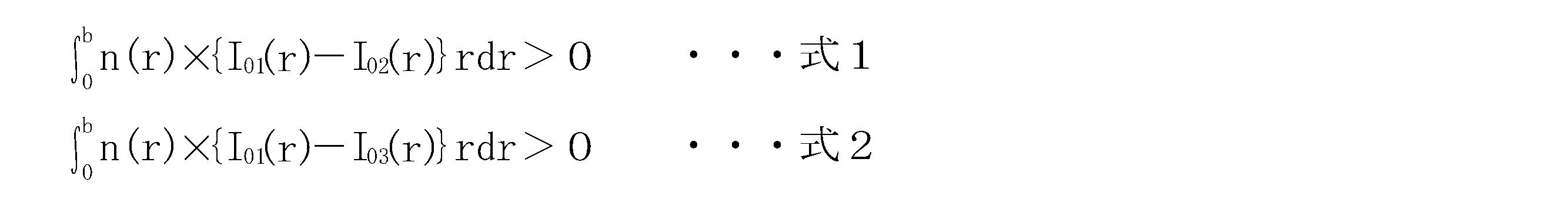
The core propagates light of a predetermined wavelength in at least the LP01 mode, the LP02 mode, and the LP03 mode,
In the core, when the LP01 mode, the LP02 mode, and the LP03 mode are normalized by power, the strength of the LP01 mode is at least in a region that is stronger than at least one of the LP02 mode and the LP03 mode. In part, an active element that stimulates and emits light of the predetermined wavelength is added at a higher concentration than the central portion of the core,
An amplification optical fiber satisfying at least one of the following formulas 1 and 2.
- 前記コアには、前記LP01モード及び前記LP02モード及び前記LP03モードをパワーで規格化する場合における、前記LP01モードの強度が、前記LP02モードの強度よりも強い領域の少なくとも一部、及び、前記LP01モードの強度が、前記LP03モードの強度よりも強い領域の少なくとも一部において、前記活性元素が、前記コアの中心部よりも高い濃度で添加され、
前記式1及び前記式2の両方を満たすことを特徴とする請求項1に記載の増幅用光ファイバ。 In the core, when the LP01 mode, the LP02 mode, and the LP03 mode are normalized by power, at least a part of a region where the intensity of the LP01 mode is stronger than the intensity of the LP02 mode, and the LP01 mode In at least a part of the region where the strength of the mode is stronger than that of the LP03 mode, the active element is added at a higher concentration than the central portion of the core;
The amplification optical fiber according to claim 1, wherein both the expression 1 and the expression 2 are satisfied. - 前記コアには、前記LP01モード及び前記LP02モード及び前記LP03モードをパワーで規格化する場合における、前記LP01モードの強度が前記LP02モードの強度及び前記LP03モードの強度よりも強い領域の少なくとも一部において、前記活性元素が、前記コアの中心部よりも高い濃度で添加されていることを特徴とする請求項2に記載の光ファイバ。 In the core, when the LP01 mode, the LP02 mode, and the LP03 mode are normalized by power, at least a part of a region where the strength of the LP01 mode is stronger than the strength of the LP02 mode and the strength of the LP03 mode 3. The optical fiber according to claim 2, wherein the active element is added at a concentration higher than that of the central portion of the core.
- 前記コアには、前記LP01モード及び前記LP02モード及び前記LP03モードをパワーで規格化する場合における、前記LP01モードの強度が前記LP02モードの強度及び前記LP03モードの強度よりも強い領域の全てにおいて、前記活性元素が、前記コアの中心部よりも高い濃度で添加されていることを特徴とする請求項3に記載の光ファイバ。 In the core, when the LP01 mode, the LP02 mode, and the LP03 mode are normalized by power, the LP01 mode strength is higher than the LP02 mode strength and the LP03 mode strength in all regions. The optical fiber according to claim 3, wherein the active element is added at a concentration higher than that of the central portion of the core.
- 前記コアには、前記LP01モード及び前記LP02モード及び前記LP03モードをパワーで規格化する場合における、前記LP01モードの強度が、前記LP02モード及び前記LP03モードの少なくとも一方の強度よりも強い領域の全てにおいて、前記活性元素が、前記コアの中心部よりも高い濃度で添加され、
前記式1及び前記式2の両方を満たすことを特徴とする請求項1に記載の増幅用光ファイバ。 The core includes all the regions where the strength of the LP01 mode is higher than the strength of at least one of the LP02 mode and the LP03 mode when the LP01 mode, the LP02 mode, and the LP03 mode are normalized by power. In the above, the active element is added at a concentration higher than the central portion of the core,
The amplification optical fiber according to claim 1, wherein both the expression 1 and the expression 2 are satisfied. - 前記コアの前記中心部には、前記活性元素が添加されていないことを特徴とする請求項1~5のいずれか1項に記載の増幅用光ファイバ。 The amplification optical fiber according to any one of claims 1 to 5, wherein the active element is not added to the central portion of the core.
- 前記コアの外周部においては、前記コアの中心部よりも活性元素が高い濃度で添加される領域よりも、前記活性元素の濃度が低くされていることを特徴とする請求項1~6のいずれか1項に記載の増幅用光ファイバ。 The active element concentration in the outer peripheral portion of the core is lower than that in a region where the active element is added at a higher concentration than the central portion of the core. 2. An optical fiber for amplification according to item 1.
- 前記コアの前記外周部には、活性元素が添加されていないことを特徴とする請求項7に記載の増幅用光ファイバ。 The optical fiber for amplification according to claim 7, wherein an active element is not added to the outer peripheral portion of the core.
- 前記コアを挟む一対の応力付与部が、前記クラッド内に設けられることを特徴とする請求項1~8のいずれか1項に記載の増幅用光ファイバ。 9. The amplification optical fiber according to claim 1, wherein a pair of stress applying portions sandwiching the core is provided in the clad.
- 請求項1から9のいずれか1項に記載の増幅用光ファイバと、
LP01モードを含む種光を前記増幅用光ファイバに入力させる種光源と、
前記増幅用光ファイバの前記活性元素を励起する励起光を出力する励起光源と、
を備えることを特徴とする光ファイバ増幅器。 An amplification optical fiber according to any one of claims 1 to 9,
A seed light source for inputting seed light including an LP01 mode into the amplification optical fiber;
An excitation light source that outputs excitation light for exciting the active element of the amplification optical fiber;
An optical fiber amplifier comprising: - 前記増幅用光ファイバに入力する種光は、前記増幅用光ファイバの軸対称のモードのみを励振することを特徴とする請求項10に記載の光ファイバ増幅器。 The optical fiber amplifier according to claim 10, wherein the seed light input to the amplification optical fiber excites only an axially symmetric mode of the amplification optical fiber.
- 前記増幅用光ファイバに入力する種光は、シングルモード光であることを特徴とする請求項11に記載の光ファイバ増幅器。 The optical fiber amplifier according to claim 11, wherein the seed light input to the amplification optical fiber is single mode light.
- 請求項1から9のいずれか1項に記載の増幅用光ファイバと、
前記増幅用光ファイバの前記活性元素を励起する励起光を出力する励起光源と、
前記増幅用光ファイバの一方側に設けられ、前記励起光により励起された前記活性元素が放出する光の少なくとも一部の波長の光を反射する第1FBGと、
前記増幅用光ファイバの他方側に設けられ、前記第1FBGが反射する光と同じ波長の光を前記第1FBGよりも低い反射率で反射する第2FBGと、
を備えることを特徴とする共振器。 An amplification optical fiber according to any one of claims 1 to 9,
An excitation light source that outputs excitation light for exciting the active element of the amplification optical fiber;
A first FBG that is provided on one side of the amplification optical fiber and reflects light having a wavelength of at least a part of light emitted by the active element excited by the excitation light;
A second FBG that is provided on the other side of the amplification optical fiber and reflects light having the same wavelength as the light reflected by the first FBG with a lower reflectance than the first FBG;
A resonator comprising:
Priority Applications (3)
| Application Number | Priority Date | Filing Date | Title |
|---|---|---|---|
| EP11837871.0A EP2642620B1 (en) | 2010-11-02 | 2011-10-18 | Amplifying optical fiber, and optical fiber amplifier and oscillator using same |
| CN201180052335.2A CN103262367B (en) | 2010-11-02 | 2011-10-18 | Amplifying optical fiber, and optical fiber amplifier and oscillator using same |
| DK11837871.0T DK2642620T3 (en) | 2010-11-02 | 2011-10-18 | AMPLIFIED OPTICAL FIBER, OPTICAL FIBER AMPLIFIER AND OSCILLATOR BY USING THE SAME |
Applications Claiming Priority (2)
| Application Number | Priority Date | Filing Date | Title |
|---|---|---|---|
| JP2010-246360 | 2010-11-02 | ||
| JP2010246360A JP4667535B1 (en) | 2010-11-02 | 2010-11-02 | Amplifying optical fiber, and optical fiber amplifier and resonator using the same |
Publications (1)
| Publication Number | Publication Date |
|---|---|
| WO2012060220A1 true WO2012060220A1 (en) | 2012-05-10 |
Family
ID=44021698
Family Applications (1)
| Application Number | Title | Priority Date | Filing Date |
|---|---|---|---|
| PCT/JP2011/073955 WO2012060220A1 (en) | 2010-11-02 | 2011-10-18 | Amplifying optical fiber, and optical fiber amplifier and oscillator using same |
Country Status (6)
| Country | Link |
|---|---|
| US (1) | US8456737B2 (en) |
| EP (1) | EP2642620B1 (en) |
| JP (1) | JP4667535B1 (en) |
| CN (1) | CN103262367B (en) |
| DK (1) | DK2642620T3 (en) |
| WO (1) | WO2012060220A1 (en) |
Cited By (1)
| Publication number | Priority date | Publication date | Assignee | Title |
|---|---|---|---|---|
| WO2022054287A1 (en) * | 2020-09-14 | 2022-03-17 | 日本電信電話株式会社 | Rare-earth-added optical fiber and optical fiber amplifier |
Families Citing this family (21)
| Publication number | Priority date | Publication date | Assignee | Title |
|---|---|---|---|---|
| CN103460525B (en) * | 2011-03-31 | 2015-04-08 | 株式会社藤仓 | Amplification optical fibre, and optical fibre amplifier and resonator using same |
| JP5727305B2 (en) * | 2011-06-13 | 2015-06-03 | 日本電信電話株式会社 | Optical fiber amplifier |
| US8638493B2 (en) * | 2011-09-16 | 2014-01-28 | Alcatel Lucent | Optical system for signal amplification using a multimode fiber |
| JP5694266B2 (en) * | 2012-10-02 | 2015-04-01 | 株式会社フジクラ | Optical fiber and fiber laser device using the same |
| JP5771586B2 (en) * | 2012-10-16 | 2015-09-02 | 株式会社フジクラ | Optical fiber and fiber laser device using the same |
| JP6005472B2 (en) * | 2012-10-24 | 2016-10-12 | 日本電信電話株式会社 | Optical fiber |
| US9645310B2 (en) * | 2013-07-25 | 2017-05-09 | B.G. Negev Technologies And Applications Ltd. | Single large mode cladding amplification in active double-clad fibers |
| US10069271B2 (en) | 2014-06-02 | 2018-09-04 | Nlight, Inc. | Scalable high power fiber laser |
| JP6511235B2 (en) * | 2014-09-01 | 2019-05-15 | 株式会社フジクラ | Fiber laser device |
| US10520671B2 (en) * | 2015-07-08 | 2019-12-31 | Nlight, Inc. | Fiber with depressed central index for increased beam parameter product |
| US11179807B2 (en) | 2015-11-23 | 2021-11-23 | Nlight, Inc. | Fine-scale temporal control for laser material processing |
| JP6268232B2 (en) * | 2016-07-04 | 2018-01-24 | 株式会社フジクラ | Optical fiber and laser device |
| CN109716184B (en) * | 2016-07-20 | 2022-12-02 | 罗切斯特大学 | LMA fiber for suppressing thermal mode instability |
| CN109791252B (en) | 2016-09-29 | 2021-06-29 | 恩耐公司 | Adjustable beam characteristics |
| US10732439B2 (en) | 2016-09-29 | 2020-08-04 | Nlight, Inc. | Fiber-coupled device for varying beam characteristics |
| US10730785B2 (en) | 2016-09-29 | 2020-08-04 | Nlight, Inc. | Optical fiber bending mechanisms |
| JP6668272B2 (en) * | 2017-01-27 | 2020-03-18 | 株式会社フジクラ | Optical fiber for amplification |
| FI3612872T3 (en) * | 2017-04-21 | 2023-05-08 | Nuburu Inc | Multi-clad optical fiber |
| US10969611B2 (en) * | 2017-07-14 | 2021-04-06 | The Government Of The United States Of America, As Represented By The Secretary Of The Navy | Devices for transmitting a modulated optical signal using a few-mode fiber |
| US20220094131A1 (en) * | 2019-03-29 | 2022-03-24 | Fujikura Ltd. | Active element-added optical fiber, resonator, and fiber laser device |
| EP3869636B1 (en) * | 2020-02-21 | 2024-03-13 | Toyota Jidosha Kabushiki Kaisha | Amplification fiber and laser beam emitting apparatus |
Citations (6)
| Publication number | Priority date | Publication date | Assignee | Title |
|---|---|---|---|---|
| US5121460A (en) | 1991-01-31 | 1992-06-09 | The Charles Stark Draper Lab., Inc. | High-power mode-selective optical fiber laser |
| US5818630A (en) | 1997-06-25 | 1998-10-06 | Imra America, Inc. | Single-mode amplifiers and compressors based on multi-mode fibers |
| JP2003008114A (en) * | 2001-06-25 | 2003-01-10 | Mitsubishi Cable Ind Ltd | Rare-earth element-doped optical fiber |
| WO2003067723A1 (en) * | 2002-02-06 | 2003-08-14 | Mitsubishi Denki Kabushiki Kaisha | Multimode optical fiber, fiber laser amplifier, and fiber laser oscillator |
| JP2006128384A (en) * | 2004-10-28 | 2006-05-18 | Hitachi Cable Ltd | Fiber laser, optical fiber therefor, and laser oscillation method |
| JP2006516811A (en) * | 2003-01-24 | 2006-07-06 | トルンプフ インコーポレイテッド | Fiber laser |
Family Cites Families (3)
| Publication number | Priority date | Publication date | Assignee | Title |
|---|---|---|---|---|
| US5966481A (en) * | 1997-12-23 | 1999-10-12 | Northern Telecom Limited | Optically pumped optical waveguide amplifier |
| US8068705B2 (en) * | 2009-09-14 | 2011-11-29 | Gapontsev Valentin P | Single-mode high-power fiber laser system |
| US8498044B2 (en) * | 2009-12-22 | 2013-07-30 | Fujikura Ltd. | Amplification optical fiber, and optical fiber amplifier and resonator using the same |
-
2010
- 2010-11-02 JP JP2010246360A patent/JP4667535B1/en active Active
-
2011
- 2011-01-06 US US12/985,491 patent/US8456737B2/en active Active
- 2011-10-18 DK DK11837871.0T patent/DK2642620T3/en active
- 2011-10-18 WO PCT/JP2011/073955 patent/WO2012060220A1/en active Application Filing
- 2011-10-18 CN CN201180052335.2A patent/CN103262367B/en active Active
- 2011-10-18 EP EP11837871.0A patent/EP2642620B1/en active Active
Patent Citations (6)
| Publication number | Priority date | Publication date | Assignee | Title |
|---|---|---|---|---|
| US5121460A (en) | 1991-01-31 | 1992-06-09 | The Charles Stark Draper Lab., Inc. | High-power mode-selective optical fiber laser |
| US5818630A (en) | 1997-06-25 | 1998-10-06 | Imra America, Inc. | Single-mode amplifiers and compressors based on multi-mode fibers |
| JP2003008114A (en) * | 2001-06-25 | 2003-01-10 | Mitsubishi Cable Ind Ltd | Rare-earth element-doped optical fiber |
| WO2003067723A1 (en) * | 2002-02-06 | 2003-08-14 | Mitsubishi Denki Kabushiki Kaisha | Multimode optical fiber, fiber laser amplifier, and fiber laser oscillator |
| JP2006516811A (en) * | 2003-01-24 | 2006-07-06 | トルンプフ インコーポレイテッド | Fiber laser |
| JP2006128384A (en) * | 2004-10-28 | 2006-05-18 | Hitachi Cable Ltd | Fiber laser, optical fiber therefor, and laser oscillation method |
Non-Patent Citations (1)
| Title |
|---|
| RICHARD S. QUIMBY ET AL.: "Yb3+ Ring Doping in High-Order-Mode Fiberfor High-Power 977-nm Lasers and Amplifiers", IEEE JOURNAL OF SELECTED TOPICS IN QUANTUM ELECTRONICS, vol. 15, no. 1, January 2009 (2009-01-01), pages 12 - 19, XP055090261 * |
Cited By (1)
| Publication number | Priority date | Publication date | Assignee | Title |
|---|---|---|---|---|
| WO2022054287A1 (en) * | 2020-09-14 | 2022-03-17 | 日本電信電話株式会社 | Rare-earth-added optical fiber and optical fiber amplifier |
Also Published As
| Publication number | Publication date |
|---|---|
| EP2642620A4 (en) | 2018-02-07 |
| US8456737B2 (en) | 2013-06-04 |
| US20120105947A1 (en) | 2012-05-03 |
| JP4667535B1 (en) | 2011-04-13 |
| EP2642620B1 (en) | 2019-11-13 |
| CN103262367A (en) | 2013-08-21 |
| CN103262367B (en) | 2015-03-18 |
| EP2642620A1 (en) | 2013-09-25 |
| DK2642620T3 (en) | 2020-02-17 |
| JP2012099649A (en) | 2012-05-24 |
Similar Documents
| Publication | Publication Date | Title |
|---|---|---|
| JP4667535B1 (en) | Amplifying optical fiber, and optical fiber amplifier and resonator using the same | |
| JP5159956B2 (en) | Amplifying optical fiber, and optical fiber amplifier and resonator using the same | |
| JP5468666B2 (en) | Amplifying optical fiber, and optical fiber amplifier and resonator using the same | |
| JP5779606B2 (en) | Amplifying optical fiber and fiber laser device using the same | |
| JP5238509B2 (en) | Photonic bandgap fiber | |
| JP5694266B2 (en) | Optical fiber and fiber laser device using the same | |
| WO2016035414A1 (en) | Fiber laser device | |
| JP5771586B2 (en) | Optical fiber and fiber laser device using the same | |
| JP5982307B2 (en) | Photonic band gap fiber and fiber laser device using the same | |
| JP5643632B2 (en) | Multi-port coupler, and optical fiber amplifier, fiber laser apparatus and resonator using the same | |
| WO2019131971A1 (en) | Optical fiber and laser device | |
| WO2019021565A1 (en) | Fiber laser device |
Legal Events
| Date | Code | Title | Description |
|---|---|---|---|
| 121 | Ep: the epo has been informed by wipo that ep was designated in this application |
Ref document number: 11837871 Country of ref document: EP Kind code of ref document: A1 |
|
| NENP | Non-entry into the national phase |
Ref country code: DE |
|
| WWE | Wipo information: entry into national phase |
Ref document number: 2011837871 Country of ref document: EP |