WO2012056680A1 - 立体視画像表示装置 - Google Patents
立体視画像表示装置 Download PDFInfo
- Publication number
- WO2012056680A1 WO2012056680A1 PCT/JP2011/005943 JP2011005943W WO2012056680A1 WO 2012056680 A1 WO2012056680 A1 WO 2012056680A1 JP 2011005943 W JP2011005943 W JP 2011005943W WO 2012056680 A1 WO2012056680 A1 WO 2012056680A1
- Authority
- WO
- WIPO (PCT)
- Prior art keywords
- image display
- eye image
- half mirror
- display surface
- stereoscopic
- Prior art date
- Legal status (The legal status is an assumption and is not a legal conclusion. Google has not performed a legal analysis and makes no representation as to the accuracy of the status listed.)
- Ceased
Links
Images







Classifications
-
- G—PHYSICS
- G02—OPTICS
- G02B—OPTICAL ELEMENTS, SYSTEMS OR APPARATUS
- G02B27/00—Optical systems or apparatus not provided for by any of the groups G02B1/00 - G02B26/00, G02B30/00
- G02B27/10—Beam splitting or combining systems
- G02B27/14—Beam splitting or combining systems operating by reflection only
- G02B27/144—Beam splitting or combining systems operating by reflection only using partially transparent surfaces without spectral selectivity
-
- A—HUMAN NECESSITIES
- A61—MEDICAL OR VETERINARY SCIENCE; HYGIENE
- A61B—DIAGNOSIS; SURGERY; IDENTIFICATION
- A61B6/00—Apparatus or devices for radiation diagnosis; Apparatus or devices for radiation diagnosis combined with radiation therapy equipment
- A61B6/02—Arrangements for diagnosis sequentially in different planes; Stereoscopic radiation diagnosis
- A61B6/022—Stereoscopic imaging
-
- A—HUMAN NECESSITIES
- A61—MEDICAL OR VETERINARY SCIENCE; HYGIENE
- A61B—DIAGNOSIS; SURGERY; IDENTIFICATION
- A61B6/00—Apparatus or devices for radiation diagnosis; Apparatus or devices for radiation diagnosis combined with radiation therapy equipment
- A61B6/46—Arrangements for interfacing with the operator or the patient
- A61B6/461—Displaying means of special interest
- A61B6/464—Displaying means of special interest involving a plurality of displays
-
- G—PHYSICS
- G02—OPTICS
- G02B—OPTICAL ELEMENTS, SYSTEMS OR APPARATUS
- G02B27/00—Optical systems or apparatus not provided for by any of the groups G02B1/00 - G02B26/00, G02B30/00
- G02B27/10—Beam splitting or combining systems
- G02B27/1073—Beam splitting or combining systems characterized by manufacturing or alignment methods
-
- G—PHYSICS
- G02—OPTICS
- G02B—OPTICAL ELEMENTS, SYSTEMS OR APPARATUS
- G02B30/00—Optical systems or apparatus for producing three-dimensional [3D] effects, e.g. stereoscopic images
- G02B30/20—Optical systems or apparatus for producing three-dimensional [3D] effects, e.g. stereoscopic images by providing first and second parallax images to an observer's left and right eyes
- G02B30/22—Optical systems or apparatus for producing three-dimensional [3D] effects, e.g. stereoscopic images by providing first and second parallax images to an observer's left and right eyes of the stereoscopic type
- G02B30/25—Optical systems or apparatus for producing three-dimensional [3D] effects, e.g. stereoscopic images by providing first and second parallax images to an observer's left and right eyes of the stereoscopic type using polarisation techniques
-
- G—PHYSICS
- G03—PHOTOGRAPHY; CINEMATOGRAPHY; ANALOGOUS TECHNIQUES USING WAVES OTHER THAN OPTICAL WAVES; ELECTROGRAPHY; HOLOGRAPHY
- G03B—APPARATUS OR ARRANGEMENTS FOR TAKING PHOTOGRAPHS OR FOR PROJECTING OR VIEWING THEM; APPARATUS OR ARRANGEMENTS EMPLOYING ANALOGOUS TECHNIQUES USING WAVES OTHER THAN OPTICAL WAVES; ACCESSORIES THEREFOR
- G03B35/00—Stereoscopic photography
- G03B35/18—Stereoscopic photography by simultaneous viewing
-
- H—ELECTRICITY
- H04—ELECTRIC COMMUNICATION TECHNIQUE
- H04N—PICTORIAL COMMUNICATION, e.g. TELEVISION
- H04N13/00—Stereoscopic video systems; Multi-view video systems; Details thereof
- H04N13/30—Image reproducers
-
- H—ELECTRICITY
- H04—ELECTRIC COMMUNICATION TECHNIQUE
- H04N—PICTORIAL COMMUNICATION, e.g. TELEVISION
- H04N13/00—Stereoscopic video systems; Multi-view video systems; Details thereof
- H04N13/30—Image reproducers
- H04N13/346—Image reproducers using prisms or semi-transparent mirrors
-
- A—HUMAN NECESSITIES
- A61—MEDICAL OR VETERINARY SCIENCE; HYGIENE
- A61B—DIAGNOSIS; SURGERY; IDENTIFICATION
- A61B6/00—Apparatus or devices for radiation diagnosis; Apparatus or devices for radiation diagnosis combined with radiation therapy equipment
- A61B6/50—Apparatus or devices for radiation diagnosis; Apparatus or devices for radiation diagnosis combined with radiation therapy equipment specially adapted for specific body parts; specially adapted for specific clinical applications
- A61B6/502—Apparatus or devices for radiation diagnosis; Apparatus or devices for radiation diagnosis combined with radiation therapy equipment specially adapted for specific body parts; specially adapted for specific clinical applications for diagnosis of breast, i.e. mammography
-
- H—ELECTRICITY
- H04—ELECTRIC COMMUNICATION TECHNIQUE
- H04N—PICTORIAL COMMUNICATION, e.g. TELEVISION
- H04N2213/00—Details of stereoscopic systems
- H04N2213/001—Constructional or mechanical details
Definitions
- the present invention relates to a stereoscopic image display device that displays a stereoscopic image using two images, a right-eye image and a left-eye image.
- stereoscopic viewing can be performed using parallax by displaying a combination of two images, a right-eye image and a left-eye image.
- a stereoscopically viewable image hereinafter referred to as a stereoscopic image or a stereo image
- a stereoscopic image or a stereo image is generated based on a plurality of images having parallax obtained by photographing the same subject from different positions.
- stereoscopic images is used not only in the fields of digital cameras and televisions, but also in the field of radiographic imaging. That is, the subject is irradiated with radiation from different directions, the radiation transmitted through the subject is detected by the radiation image detector, and a plurality of radiation images having parallax are obtained, and based on these radiation images A stereoscopic image is generated. And by generating a stereoscopic image in this way, a radiographic image with a sense of depth can be observed, and a radiographic image more suitable for diagnosis can be observed. (For example, see Patent Document 1)
- a stereoscopic image display device for displaying a stereoscopic image as described above, it is provided with two display screens arranged side by side and a half mirror, and displays a right eye image and a left eye image on each display screen.
- a monitor that displays a stereoscopic image by optically synthesizing a right-eye image and a left-eye image with a half mirror.
- the display screen in the stereoscopic image display apparatus of such a system can be the same as that for displaying a normal image, the display of the stereoscopic image and the display of the normal image can be combined.
- the half mirror interferes with display during normal image display.
- the present invention aims to provide a stereoscopic image display device that displays a stereoscopic image using two images, a right-eye image and a left-eye image, in which the above-described problems are solved.
- a stereoscopic image display device is a stereoscopic image display device capable of displaying both a stereoscopic image and a normal image using two images of a right-eye image and a left-eye image.
- the right-eye image display means for displaying the normal image and the right-eye image display means are arranged horizontally, and the left-eye image display means for displaying the left-eye image and the normal image, and the right-eye image and the left-eye image are stereoscopically viewed.
- the display surface front and left-eye images of the right-eye image display means From the intermediate position between the half mirror optically combined so that it can be seen as an image, and the display surface of the right-eye image display means and the display surface of the left-eye image display means, the display surface front and left-eye images of the right-eye image display means And a half mirror moving mechanism capable of moving the half mirror to a position where the display means does not enter the front of the display surface.
- the half mirror moving mechanism is configured such that the display screen front of the right eye image display means and the display surface of the left eye image display means are in front of the intermediate position between the display surface of the right eye image display means and the display surface of the left eye image display means.
- the half mirror may be configured to be movable in the horizontal direction up to a position where it does not enter.
- the half mirror moving mechanism is configured such that the display surface front of the right eye image display means and the display surface front of the left eye image display means are determined from an intermediate position between the display surface of the right eye image display means and the display surface of the left eye image display means.
- the half mirror may be configured to be movable in the vertical direction to a position where it does not enter.
- the half mirror moving mechanism is configured such that the half mirror has a display surface of the right eye image display means and a left eye image display means with the vertical one side of the right eye image display means or the left eye image display means as a first rotation axis. Rotates from an intermediate position with respect to the display surface to the vicinity of the display surface of the right-eye image display means and / or to the vicinity of the display surface of the left-eye image display means, and the half mirror is close to the display surface of the right-eye image display means and / or to the left eye
- the upper side of the half mirror may be configured to be rotatable upward with the second rotation axis as the second rotation axis.
- the half mirror moving mechanism may be configured to be rotatable from a position where the half mirror is in the vertical direction to a position where it is in the horizontal direction with the lower side of the half mirror as the rotation axis.
- a half-mirror moving mechanism that can move to a position that does not enter the front of the display surface and the front of the display surface of the left-eye image display means, it is possible to prevent the half mirror from obstructing display during normal image display.
- the display of the visual image and the display of the normal image can be combined.
- the half mirror moving mechanism From the intermediate position between the display surface of the right-eye image display means and the display surface of the left-eye image display means, the front of the display surface of the right-eye image display means and the display surface of the left-eye image display means It is assumed that the half mirror can be moved in the horizontal direction to a position where it does not invade the right side, or for the right eye from the intermediate position between the display surface of the right eye image display means and the display surface of the left eye image display means.
- the half mirror is configured to be movable in the vertical direction to a position that does not enter the front of the display surface of the image display means and the display surface of the left-eye image display means, or the right-eye image display means or the left-eye image Using the one side in the vertical direction of the display means as the first rotation axis, the half mirror is positioned from the intermediate position between the display surface of the right eye image display means and the display surface of the left eye image display means, When the display is rotated to the vicinity of the display surface of the display means and / or the display surface of the left-eye image display means, and the half mirror is near the display surface of the right-eye image display means and / or the display surface of the left-eye image display means.
- the upper side of the half mirror can be rotated upward with the second rotation axis as the second rotation axis, or the half mirror is in the horizontal direction from the vertical position with the lower side of the half mirror as the rotation axis. If it is configured to be able to rotate to the minimum,
- FIG. 1 is a schematic configuration diagram of a breast stereoscopic image photographing display system using a stereoscopic image display apparatus according to a first embodiment of the present invention.
- the figure which looked at the arm part of the stereoscopic vision image photographing display system for breasts shown in FIG. 1 from the right direction of FIG. 1 is a block diagram showing a schematic configuration inside a computer of the breast stereoscopic image capturing and displaying system shown in FIG.
- the top view which shows the state at the time of the stereoscopic image display of the said stereoscopic vision image display apparatus The top view which shows the state at the time of the normal image display of the said stereoscopic vision image display apparatus.
- the top view which shows the state at the time of the stereoscopic image display of the other stereoscopic vision image display apparatus Top view (1) which shows the state at the time of the half mirror movement of other stereoscopic vision image display apparatuses
- Top view (2) which shows the state at the time of the half mirror movement of other stereoscopic vision image display apparatuses The top view which shows the state at the time of the normal image display of the other stereoscopic vision image display apparatus.
- the perspective view of the stereoscopic vision image display apparatus of the 2nd Embodiment of this invention The top view which shows the state at the time of the stereoscopic image display of the said stereoscopic vision image display apparatus
- the top view which shows the state at the time of the normal image display of the said stereoscopic vision image display apparatus The
- the side view which shows the state at the time of the normal image display of the said stereoscopic vision image display apparatus The perspective view of the stereoscopic vision image display apparatus of the 4th Embodiment of this invention
- the top view which shows the state at the time of the stereoscopic image display of the said stereoscopic vision image display apparatus The top view which shows the state at the time of the normal image display of the said stereoscopic vision image display apparatus
- FIG. 1 is a schematic configuration diagram of a breast stereoscopic image photographing / displaying system using the stereoscopic image displaying apparatus of the present embodiment
- FIG. 2 is a diagram illustrating an arm unit of the breast stereoscopic image photographing / displaying system shown in FIG.
- FIG. 3 is a block diagram showing a schematic configuration inside a computer of the breast stereoscopic image capturing and displaying system shown in FIG. 1, FIG.
- FIG. 4 is a perspective view of the stereoscopic image display device
- FIG. FIG. 6 is a top view showing a state of the stereoscopic image display device when displaying a stereoscopic image
- FIG. 6 is a top view showing a state of the stereoscopic image display device when displaying a normal image
- FIG. 7 is another stereoscopic image display device
- FIG. 8 is a top view showing a state when a half mirror of another stereoscopic image display device is moved
- FIG. 9 is a half view of the other stereoscopic image display device.
- Top view (2) and figure showing the state of mirror movement 0 is a top view showing a conventional image display state when the other of the stereoscopic image display apparatus.
- a breast stereoscopic imaging and displaying system 1 includes a breast imaging device 10, a computer 8 connected to the breast imaging device 10, and a monitor 9 connected to the computer 8. (Stereoscopic image display device) and an input unit 7 are provided.
- the mammography apparatus 10 includes a base 11, a rotary shaft 12 that can move in the vertical direction (Z direction) with respect to the base 11, and can rotate.
- the arm part 13 connected with the base 11 is provided.
- FIG. 2 shows the arm 13 viewed from the right direction in FIG.
- the arm section 13 has an alphabet C shape, and a radiation table 16 is attached to one end of the arm section 13 so as to face the imaging table 14 at the other end.
- the rotation and vertical movement of the arm unit 13 are controlled by an arm controller 31 incorporated in the base 11.
- a radiation image detector 15 such as a flat panel detector and a detector controller 33 that controls reading of a charge signal from the radiation image detector 15.
- a charge amplifier that converts the charge signal read from the radiation image detector 15 into a voltage signal
- a correlated double sampling circuit that samples the voltage signal output from the charge amplifier
- a circuit board provided with an AD conversion unit for converting a voltage signal into a digital signal is also installed.
- the photographing table 14 is configured to be rotatable with respect to the arm unit 13, and even when the arm unit 13 rotates with respect to the base 11, the direction of the photographing table 14 is fixed to the base 11. can do.
- the radiation image detector 15 can repeatedly perform recording and reading of a radiation image, and may use a so-called direct type radiation image detector that directly receives radiation and generates charges. Alternatively, a so-called indirect radiation image detector that converts radiation once into visible light and converts the visible light into a charge signal may be used.
- a radiation image signal readout method a radiation image signal is read out by turning on / off a TFT (thin film transistor) switch, or by irradiating reading light. It is desirable to use a so-called optical readout system from which a radiation image signal is read out, but the present invention is not limited to this, and other systems may be used.
- a radiation source 17 and a radiation source controller 32 are accommodated in the radiation irradiation unit 16.
- the radiation source controller 32 controls the timing of irradiating radiation from the radiation source 17 and the radiation generation conditions (tube current, tube voltage, time, etc.) in the radiation source 17.
- a compression plate 18 that is disposed above the imaging table 14 and presses against the breast M, a support portion 20 that supports the compression plate 18, and the support portion 20 in the vertical direction.
- a moving mechanism 19 for moving in the (Z direction) is provided. The position of the compression plate 18 and the compression pressure are controlled by the compression plate controller 34.
- the computer 8 includes a central processing unit (CPU), a storage device such as a semiconductor memory, a hard disk, and an SSD.
- the control unit 8a, the data storage unit 8b, and the image processing unit shown in FIG. Part 8c is configured.
- the controller 8a outputs predetermined control signals to the various controllers 31 to 34 to control the entire system. A specific control method will be described in detail later.
- the data storage unit 8b stores radiation image data and the like for each imaging angle acquired by the radiation image detector 15.
- the image processing unit 8c is for performing various image processing.
- the input unit 7 is composed of a pointing device such as a keyboard and a mouse, for example, and is used to accept input of a movement operation of a three-dimensional cursor, shooting conditions, operation instructions, and the like.
- the monitor 9 is capable of displaying both a stereoscopic image and a normal image using two images of a right eye image and a left eye image. As shown in FIG. 4, the right eye image and the normal image are displayed.
- the right-eye image display unit 40 and the right-eye image display unit 40 to be displayed are arranged horizontally, and the left-eye image display unit 41 that displays the left-eye image and the normal image, and the right-eye image and the left-eye image are stereoscopically viewed.
- a half mirror 42 that is optically combined so as to be seen as an image.
- the half mirror 42 is held on a base 43 provided with a rail 43a so as to be movable in the horizontal direction along the rail 43a.
- the horizontal direction means a direction parallel to the installation surface of the monitor 9, but the moving direction of the half mirror 42 is not limited to a direction completely parallel to the installation surface of the monitor 9.
- the monitor 9 may be inclined with respect to the installation surface.
- the display light in the right-eye image display unit 40 and the left-eye image display unit 41 is configured to be polarized light orthogonal to each other.
- the user wears polarizing glasses having a right-eye polarizing lens for observing the right-eye image and a left-eye polarizing lens for observing the left-eye image, and observes the left-eye image and the right-eye image with the left and right eyes, respectively. Visual images can be observed.
- the half mirror 42 is placed between the display surface 40 a of the right-eye image display unit 40 and the display surface 41 a of the left-eye image display unit 41. Move to position.
- the half mirror 42 may be moved manually by the user, or an input unit such as a switch for receiving an instruction input for stereoscopic image display is provided, and the half mirror 42 is automatically moved based on the instruction from the input unit. It may be configured to move the image automatically when it detects that a stereoscopic image signal has been input based on the radiation image signal input to the monitor 9 or incidental information of the radiation image signal. You may do it.
- the angle formed between the display surface 40a of the right-eye image display unit 40 and the display surface 41a of the left-eye image display unit 41 is not particularly limited as long as it is less than 180 °, but is set to about 80 ° to 120 °. Is preferable, and 90 ° is most preferable.
- the observation of the stereoscopic image displayed on the monitor 9 can be performed from either the right side or the left side in FIG. 5, but here, the mechanism of the stereoscopic image display will be described as observing from the right side.
- FIG. 5 when a stereoscopic image is observed from the right side of the monitor 9, the right-eye image displayed on the display surface 40 a of the right-eye image display unit 40 is reflected by the half mirror 42, and the left-eye image display unit The left-eye image displayed on the display surface 41a of 41 passes through the half mirror 42, and as a result, the right-eye image and the left-eye image are optically combined and displayed as a stereoscopic image.
- the half mirror 42 is placed in front of the display surface 40 a of the right-eye image display unit 40 and the display surface 41 a of the left-eye image display unit 41. As a position that does not enter the front, it is moved in the horizontal direction along the rail 43a to a position behind the right-eye image display unit 40 and the left-eye image display unit 41.
- the normal image is a two-dimensional image, and includes a two-dimensional image when the right-eye image and the left-eye image are individually observed, and other two-dimensional images other than the right-eye image and the left-eye image.
- the half mirror 42 may be moved manually by the user, or provided with an input unit such as a switch for receiving an instruction input for normal image display, and automatically moved based on the instruction from the input unit. Alternatively, it may be automatically moved when it is detected that a normal image signal has been input based on the radiation image signal input to the monitor 9 or incidental information of the radiation image signal. May be.
- the breast M is installed on the imaging table 14, and the breast M is compressed by the compression plate 18 with a predetermined pressure.
- the control unit 8 a outputs information about the convergence angle ⁇ and the imaging angle ⁇ ′ constituting the convergence angle ⁇ to the arm controller 31.
- ⁇ 4 ° is set as information on the convergence angle ⁇ at this time
- the present invention is not limited to this, and the photographer can set an arbitrary convergence angle ⁇ at the input unit 7.
- the arm controller 31 receives the information of the imaging angle ⁇ ′ output from the control unit 8a, and the arm controller 31 first uses the arm to capture a radiographic image for the right eye based on the information of the imaging angle ⁇ ′.
- the controller 13 outputs a control signal with an imaging angle ⁇ ′ that is inclined + 2 ° with respect to a direction perpendicular to the detection surface 15a.
- the arm unit 13 rotates to a position of + 2 °.
- the control unit 8a outputs a control signal to the radiation source controller 32 and the detector controller 33 so as to perform radiation irradiation and readout of the radiation image signal.
- radiation is emitted from the radiation source 17, and a radiation image obtained by photographing the breast M from the direction in which the imaging angle ⁇ ′ is + 2 ° is detected by the radiation detector 15. Is read and stored in the data storage unit 8b of the computer 8.
- a control signal that outputs an imaging angle ⁇ ′ in which the arm unit 13 is inclined by ⁇ 2 ° with respect to a direction perpendicular to the detection surface 15a is output.
- the arm unit 13 rotates to a position of -2 °.
- the control unit 8a outputs a control signal to the radiation source controller 32 and the detector controller 33 so as to perform radiation irradiation and readout of the radiation image signal.
- radiation is emitted from the radiation source 17, and a radiation image obtained by photographing the breast M from the direction in which the imaging angle ⁇ ′ is ⁇ 2 ° is detected by the radiation detector 15.
- the signal is read out and stored in the data storage unit 8b of the computer 8.
- the half mirror 42 is moved to a position behind the right-eye image display unit 40 and the left-eye image display unit 41, the right-eye image and the left-eye image are not individually viewed as a stereoscopic image but individually. Can be observed as a two-dimensional image (normal image).
- an image other than the image for the right eye and the image for the left eye may be displayed.
- the half mirror 42 can be prevented from hindering display during normal image display, so that it is possible to display both a stereoscopic image and a normal image.
- the half mirror 42 is configured to be movable in a horizontal direction from an intermediate position with respect to the display surface 41a to a position that does not enter the front of the display surface 40a of the right-eye image display unit 40 and the front of the display surface 41a of the left-eye image display unit 41. Anything can be used.
- the present invention is not limited to this. You may incline with respect to 9 mounting surfaces. By doing so, the movement of the half mirror 42 when moving downward due to the gravity applied to the half mirror 42 can be made smooth.
- one side of the half mirror 42 in the vertical direction is held by a hinge 44, and the hinge 44 can be moved in the horizontal direction along the L-shaped rail 43b. You may make it hold
- the half mirror 42 is rotated from the state shown in FIG. 7 to a position where the half mirror 42 is parallel to the long side of the rail 43b as shown in FIG. 8, and then, as shown in FIG.
- the hinge 44 horizontally along the long side and finally moving the hinge 44 horizontally along the short side of the rail 43b as shown in FIG. 10
- the normal image display state can be obtained.
- the right-eye image display unit 40 may be moved onto the base 43 so that the display surface 40a of the right-eye image display unit 40 and the display surface 41a of the left-eye image display unit 41 are horizontal.
- FIG. 11 is a perspective view of the stereoscopic image display apparatus according to the present embodiment
- FIG. 12 is a top view showing a state when the stereoscopic image display apparatus displays a stereoscopic image
- FIG. 13 is a normal view of the stereoscopic image display apparatus. It is a top view which shows the state at the time of image display. 11 to 13, the same elements as those in FIG. 4 are denoted by the same reference numerals, and description thereof will be omitted unless particularly necessary.
- the moving direction of the half mirror 42 is different from that of the first embodiment.
- the monitor 9 a includes a right-eye image display unit 40, a left-eye image display unit 41, a half mirror 42, and an installation table 45.
- the right-eye image display unit 40 and the left-eye image display unit 41 are installed on an installation table 45.
- the half mirror 42 is held in a slit 45 a provided in the installation table 45 so as to be movable in the vertical direction with respect to the installation surface of the installation table 45 such as an image display unit.
- the half mirror 42 is placed between the display surface 40a of the right-eye image display unit 40 and the display surface 41a of the left-eye image display unit 41. Move to position.
- the half mirror 42 is placed in front of the display surface 40a of the right-eye image display unit 40 and the display surface 41a of the left-eye image display unit 41. As a position that does not enter the front, it is moved vertically to the lower side of the installation table 45.
- the half mirror 42 may be moved manually by the user, or provided with an input unit such as a switch for receiving an instruction input for each image display. May be automatically moved based on the instruction, or may be automatically moved based on the radiation image signal input to the monitor 9 or incidental information of the radiation image signal.
- an input unit such as a switch for receiving an instruction input for each image display. May be automatically moved based on the instruction, or may be automatically moved based on the radiation image signal input to the monitor 9 or incidental information of the radiation image signal.
- the mode of moving the half mirror 42 in the vertical direction is not limited to the above mode, and the half mirror 42 is displayed on the display surface 40a of the right-eye image display unit 40 during normal image display. And you may make it move to the position higher than the display surface 41a of the image display part 41 for left eyes.
- FIG. 14 is a perspective view of the stereoscopic image display device according to the present embodiment
- FIG. 15 is a top view showing a state when the stereoscopic image display device displays a stereoscopic image
- FIG. 16 is a half view of the stereoscopic image display device.
- FIG. 17 is a side view of the stereoscopic image display device as viewed from the direction indicated by the arrow A in FIG. 16, and
- FIG. 18 shows a state of the stereoscopic image display device during normal image display. It is a side view.
- FIGS. 14 to 18 the same elements as those in FIG. 4 are denoted by the same reference numerals, and description thereof will be omitted unless particularly required.
- the moving direction of the half mirror 42 is different from that of the first embodiment.
- the monitor 9 b includes a right-eye image display unit 40, a left-eye image display unit 41, and a half mirror 42.
- the half mirror 42 has a left-eye image display unit 41 via a biaxial hinge 46 in which the vertical direction of the left-eye image display unit 41 is the first rotation shaft 46a and the upper side of the half mirror 42 is the second rotation shaft 46b. Is held in.
- the half mirror 42 When displaying a stereoscopic image on the monitor 9b, as shown in FIG. 15, the half mirror 42 is placed between the display surface 40a of the right-eye image display unit 40 and the display surface 41a of the left-eye image display unit 41. Move to position.
- FIG. 17 is a side view of this state seen from the direction indicated by the arrow A in FIG. 16. From this state, as shown in FIG. 18, the half mirror 42 is rotated upward with the second rotation shaft 46b as the rotation axis.
- the normal image display state can be obtained.
- the half mirror 42 may be moved manually by the user, or provided with an input unit such as a switch for receiving an instruction input for each image display. May be automatically moved based on the instruction, or may be automatically moved based on the radiation image signal input to the monitor 9 or incidental information of the radiation image signal.
- an input unit such as a switch for receiving an instruction input for each image display. May be automatically moved based on the instruction, or may be automatically moved based on the radiation image signal input to the monitor 9 or incidental information of the radiation image signal.
- FIG. 19 is a perspective view of the stereoscopic image display device according to the present embodiment
- FIG. 20 is a top view showing a state when the stereoscopic image display device displays a stereoscopic image
- FIG. 21 is a normal view of the stereoscopic image display device. It is a top view which shows the state at the time of image display. 19 to 21, the same elements as those in FIG. 4 are denoted by the same reference numerals, and description thereof will be omitted unless particularly necessary.
- the moving direction of the half mirror 42 is different from that of the first embodiment.
- the monitor 9 a includes a right-eye image display unit 40, a left-eye image display unit 41, and a half mirror 42.
- the half mirror 42 is held on the base 47 via a hinge 47 a attached to the lower side of the half mirror 42.
- the half mirror 42 When displaying a stereoscopic image on the monitor 9a, as shown in FIG. 20, the half mirror 42 is placed between the display surface 40a of the right-eye image display unit 40 and the display surface 41a of the left-eye image display unit 41. Move to position.
- the half mirror 42 is rotated to a position in the horizontal direction with the hinge 47a as a rotation axis.
- the right-eye image display unit 40 hinders the rotational movement of the half mirror 42, so the right-eye image display unit 40 hinders the rotational movement of the half mirror 42.
- the left-eye image display unit 41 is retracted.
- the movement of the half mirror 42 and the image display unit may be manually performed by the user as in the first embodiment, or an input unit such as a switch for receiving an instruction input for each image display is provided. It may be automatically moved based on an instruction from the input unit, or may be automatically moved based on a radiation image signal input to the monitor 9 or incidental information of the radiation image signal. Also good.
- the right-eye image display unit 40 is arranged on the right side and the left-eye image display unit 41 is arranged on the left side in the above embodiment. Even when the right-eye image display unit 40 is arranged on the left side and the left-eye image display unit 41 is arranged on the right side, a stereoscopic image can be displayed in exactly the same manner.
- the stereoscopic image display apparatus of the present invention an example in which the stereoscopic image display device is combined with a breast stereoscopic image capturing and displaying system has been shown.
- the present invention is not limited to a breast stereoscopic image capturing and displaying system.
- it can be combined with any system such as a radiographic imaging device that images the chest, head, and the like.
Landscapes
- Physics & Mathematics (AREA)
- Engineering & Computer Science (AREA)
- Health & Medical Sciences (AREA)
- Life Sciences & Earth Sciences (AREA)
- Optics & Photonics (AREA)
- General Physics & Mathematics (AREA)
- Medical Informatics (AREA)
- Radiology & Medical Imaging (AREA)
- Surgery (AREA)
- Biophysics (AREA)
- High Energy & Nuclear Physics (AREA)
- Multimedia (AREA)
- Nuclear Medicine, Radiotherapy & Molecular Imaging (AREA)
- Pathology (AREA)
- Veterinary Medicine (AREA)
- Biomedical Technology (AREA)
- Heart & Thoracic Surgery (AREA)
- Molecular Biology (AREA)
- Signal Processing (AREA)
- Animal Behavior & Ethology (AREA)
- General Health & Medical Sciences (AREA)
- Public Health (AREA)
- Manufacturing & Machinery (AREA)
- Spectroscopy & Molecular Physics (AREA)
- Human Computer Interaction (AREA)
- Apparatus For Radiation Diagnosis (AREA)
- Stereoscopic And Panoramic Photography (AREA)
- Testing, Inspecting, Measuring Of Stereoscopic Televisions And Televisions (AREA)
Abstract
【課題】 右目用画像および左目用画像の2枚の画像を用いて立体視画像を表示する立体視画像表示装置において、立体視画像の表示と通常画像の表示とを兼用できるようにする。 【解決手段】 右目用画像表示部(40)と、左目用画像表示部(41)と、ハーフミラー(42)とを備えたモニタ(9)において、ハーフミラー(42)を、右目用画像表示部(40)の表示面(40a)と左目用画像表示部(41)の表示面(41a)との中間位置から右目用画像表示部(40)および左目用画像表示部(41)の後方位置まで水平方向に移動可能なように、レール(43a)が設けられた土台(43)により保持する。
Description
本発明は、右目用画像および左目用画像の2枚の画像を用いて立体視画像を表示する立体視画像表示装置に関するものである。
従来、右目用画像および左目用画像の2枚の画像を組み合わせて表示することにより、視差を利用して立体視できることが知られている。このような立体視できる画像(以下、立体視画像またはステレオ画像という)は、同一の被写体を異なる位置から撮影して取得された互いに視差のある複数の画像に基づいて生成される。
そして、このような立体視画像の生成は、デジタルカメラやテレビなどの分野だけでなく、放射線画像撮影の分野においても利用されている。すなわち、被験者に対して互いに異なる方向から放射線を照射し、その被験者を透過した放射線を放射線画像検出器によりそれぞれ検出して互いに視差のある複数の放射線画像を取得し、これらの放射線画像に基づいて立体視画像を生成することが行われている。そして、このように立体視画像を生成することによって奥行感のある放射線画像を観察することができ、より診断に適した放射線画像を観察することができる。(例えば特許文献1参照)
ところで、上記のような立体視画像を表示するための立体視画像表示装置として、左右横並びの2つの表示画面とハーフミラーを備え、各表示画面に右目用画像と左目用画像とを各々表示し、ハーフミラーで右目用画像と左目用画像とを光学的に合成して立体視画像を表示する方式のモニターが提案されている。(例えば特許文献2、3参照)
このような方式の立体視画像表示装置における表示画面は、通常画像を表示するためのものと全く同じものとすることができるため、立体視画像の表示と通常画像の表示とを兼用できるようにすることが好ましいが、その場合、通常画像表示時にハーフミラーが表示の妨げとなってしまうという問題がある。
このような方式の立体視画像表示装置における表示画面は、通常画像を表示するためのものと全く同じものとすることができるため、立体視画像の表示と通常画像の表示とを兼用できるようにすることが好ましいが、その場合、通常画像表示時にハーフミラーが表示の妨げとなってしまうという問題がある。
本発明は、上記の事情に鑑み、右目用画像および左目用画像の2枚の画像を用いて立体視画像を表示する立体視画像表示装置において、上記問題を解消したものを提供することを目的とする。
本発明の立体視画像表示装置は、右目用画像と左目用画像の2枚の画像を用いた立体視画像および通常画像の両方を表示可能な立体視画像表示装置であって、右目用画像および通常画像を表示する右目用画像表示手段と、右目用画像表示手段と水平に配され、左目用画像および通常画像を表示する左目用画像表示手段と、右目用画像と左目用画像とを立体視画像として見えるように光学的に合成するハーフミラーと、右目用画像表示手段の表示面と左目用画像表示手段の表示面との中間位置から、右目用画像表示手段の表示面前方および左目用画像表示手段の表示面前方に侵入しない位置まで、ハーフミラーを移動可能なハーフミラー移動機構とを備えてなることを特徴とするものである。
ここで、ハーフミラー移動機構は、右目用画像表示手段の表示面と左目用画像表示手段の表示面との中間位置から、右目用画像表示手段の表示面前方および左目用画像表示手段の表示面前方に侵入しない位置まで、ハーフミラーを水平方向に移動可能に構成されたものとしてもよい。
また、ハーフミラー移動機構は、右目用画像表示手段の表示面と左目用画像表示手段の表示面との中間位置から、右目用画像表示手段の表示面前方および左目用画像表示手段の表示面前方に侵入しない位置まで、ハーフミラーを垂直方向に移動可能に構成されたものとしてもよい。
また、ハーフミラー移動機構は、右目用画像表示手段または左目用画像表示手段の垂直方向の一辺を第1の回転軸として、ハーフミラーが右目用画像表示手段の表示面と左目用画像表示手段の表示面との中間位置から右目用画像表示手段の表示面近傍および/または左目用画像表示手段の表示面近傍まで回転し、かつハーフミラーが右目用画像表示手段の表示面近傍および/または左目用画像表示手段の表示面近傍にある際に、ハーフミラーの上辺を第2の回転軸として上方に回転可能に構成されたものとしてもよい。
また、ハーフミラー移動機構は、ハーフミラーの下辺を回転軸として、ハーフミラーが垂直方向となる位置から水平方向となる位置まで回転可能に構成されたものとしてもよい。
本発明の立体視画像表示装置によれば、右目用画像と左目用画像の2枚の画像を用いた立体視画像および通常画像の両方を表示可能な立体視画像表示装置において、右目用画像と左目用画像とを立体視画像として見えるように光学的に合成するハーフミラーを、右目用画像表示手段の表示面と左目用画像表示手段の表示面との中間位置から、右目用画像表示手段の表示面前方および左目用画像表示手段の表示面前方に侵入しない位置まで移動可能とするハーフミラー移動機構を設けたことにより、通常画像表示時にハーフミラーが表示の妨げとならないようにできるので、立体視画像の表示と通常画像の表示とを兼用可能とすることができる。
なお、ハーフミラー移動機構については、右目用画像表示手段の表示面と左目用画像表示手段の表示面との中間位置から、右目用画像表示手段の表示面前方および左目用画像表示手段の表示面前方に侵入しない位置まで、ハーフミラーを水平方向に移動可能に構成されたものとする、もしくは、右目用画像表示手段の表示面と左目用画像表示手段の表示面との中間位置から、右目用画像表示手段の表示面前方および左目用画像表示手段の表示面前方に侵入しない位置まで、ハーフミラーを垂直方向に移動可能に構成されたものとする、もしくは、右目用画像表示手段または左目用画像表示手段の垂直方向の一辺を第1の回転軸として、ハーフミラーが右目用画像表示手段の表示面と左目用画像表示手段の表示面との中間位置から右目用画像表示手段の表示面近傍および/または左目用画像表示手段の表示面近傍まで回転し、かつハーフミラーが右目用画像表示手段の表示面近傍および/または左目用画像表示手段の表示面近傍にある際に、ハーフミラーの上辺を第2の回転軸として上方に回転可能に構成されたものとする、もしくは、ハーフミラーの下辺を回転軸として、ハーフミラーが垂直方向となる位置から水平方向となる位置まで回転可能に構成されたものとすれば、本発明の立体視画像表示装置を容易に実現させることができる。
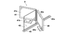
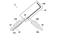
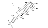
以下、図面を参照して本発明の第1の実施の形態の立体視画像表示装置を用いた乳房用立体視画像撮影表示システムについて説明する。まず、本実施の形態の乳房用立体視画像撮影表示システム全体の概略構成について説明する。図1は本実施の形態の立体視画像表示装置を用いた乳房用立体視画像撮影表示システムの概略構成図、図2は図1に示す乳房用立体視画像撮影表示システムのアーム部を図1の右方向から見た図、図3は図1に示す乳房用立体視画像撮影表示システムのコンピュータ内部の概略構成を示すブロック図、図4は上記立体視画像表示装置の斜視図、図5は上記立体視画像表示装置の立体視画像表示時の状態を示す上面図、図6は上記立体視画像表示装置の通常画像表示時の状態を示す上面図、図7はその他の立体視画像表示装置の立体視画像表示時の状態を示す上面図、図8はその他の立体視画像表示装置のハーフミラー移動時の状態を示す上面図(1)、図9はその他の立体視画像表示装置のハーフミラー移動時の状態を示す上面図(2)、図10はその他の立体視画像表示装置の通常画像表示時の状態を示す上面図である。
本実施形態の乳房用立体視画像撮影表示システム1は、図1に示すように、乳房画像撮影装置10と、乳房画像撮影装置10に接続されたコンピュータ8と、コンピュータ8に接続されたモニタ9(立体視画像表示装置)および入力部7とを備えている。
そして、乳房画像撮影装置10は、図1に示すように、基台11と、基台11に対し垂直方向(Z方向)に移動可能であり、かつ回転可能な回転軸12と、回転軸12により基台11と連結されたアーム部13を備えている。なお、図2には、図1の右方向から見たアーム部13を示している。
アーム部13はアルファベットのCの形をしており、その一端には撮影台14が、その他端には撮影台14と対向するように放射線照射部16が取り付けられている。アーム部13の回転および垂直方向の移動は、基台11に組み込まれたアームコントローラ31により制御される。
撮影台14の内部には、フラットパネルディテクタ等の放射線画像検出器15と、放射線画像検出器15からの電荷信号の読み出しを制御する検出器コントローラ33が備えられている。また、撮影台14の内部には、放射線画像検出器15から読み出された電荷信号を電圧信号に変換するチャージアンプや、チャージアンプから出力された電圧信号をサンプリングする相関2重サンプリング回路や、電圧信号をデジタル信号に変換するAD変換部などが設けられた回路基板なども設置されている。
また、撮影台14はアーム部13に対し回転可能に構成されており、基台11に対してアーム部13が回転したときでも、撮影台14の向きは基台11に対し固定された向きとすることができる。
放射線画像検出器15は、放射線画像の記録と読出しを繰り返して行うことができるものであり、放射線の照射を直接受けて電荷を発生する、いわゆる直接型の放射線画像検出器を用いてもよいし、放射線を一旦可視光に変換し、その可視光を電荷信号に変換する、いわゆる間接型の放射線画像検出器を用いるようにしてもよい。また、放射線画像信号の読出方式としては、TFT(thin film transistor)スイッチをオン・オフされることによって放射線画像信号が読みだされる、いわゆるTFT読出方式のものや、読取光を照射することによって放射線画像信号が読み出される、いわゆる光読出方式のものを用いることが望ましいが、これに限らずその他のものを用いるようにしてもよい。
放射線照射部16の中には放射線源17と、放射線源コントローラ32が収納されている。放射線源コントローラ32は、放射線源17から放射線を照射するタイミングと、放射線源17における放射線発生条件(管電流、管電圧、時間等)を制御するものである。
また、アーム部13の中央部には、撮影台14の上方に配置されて乳房Mを押さえつけて圧迫する圧迫板18と、その圧迫板18を支持する支持部20と、支持部20を垂直方向(Z方向)に移動させる移動機構19が設けられている。圧迫板18の位置、圧迫圧は、圧迫板コントローラ34により制御される。
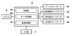
コンピュータ8は、中央処理装置(CPU)および半導体メモリやハードディスクやSSD等のストレージデバイスなどを備えており、これらのハードウェアによって、図3に示すような制御部8a、データ記憶部8bおよび画像処理部8cが構成されている。
制御部8aは、各種のコントローラ31~34に対して所定の制御信号を出力し、システム全体の制御を行うものである。具体的な制御方法については後で詳述する。データ記憶部8bは、放射線画像検出器15によって取得された撮影角度毎の放射線画像データ等を記憶するものである。画像処理部8cは種々の画像処理を施すためのものである。
入力部7は、例えば、キーボードやマウスなどのポインティングデバイスから構成されたものであり、立体カーソルの移動操作や、撮影条件や操作指示等の入力を受け付けるためのものである。
モニタ9は、右目用画像と左目用画像の2枚の画像を用いた立体視画像および通常画像の両方を表示可能なものであって、図4に示すように、右目用画像および通常画像を表示する右目用画像表示部40と、右目用画像表示部40と水平に配され、左目用画像および通常画像を表示する左目用画像表示部41と、右目用画像と左目用画像とを立体視画像として見えるように光学的に合成するハーフミラー42とを備えている。ハーフミラー42は、レール43aが設けられた土台43に、レール43aに沿って水平方向に移動可能に保持されている。
なお、ここでの水平方向とは、モニタ9の設置面に対して平行な方向を意味するが、ハーフミラー42の移動方向は、モニタ9の設置面に対して完全に平行な方向に限らず、モニタ9の設置面に対して傾いていてもよい。
右目用画像表示部40と左目用画像表示部41における表示光は互いに直交する偏光となるように構成されている。ユーザーは、右目用画像を観察する右目用偏光レンズと左目用画像を観察する左目用偏光レンズを有する偏光メガネを装着し、左目用画像および右目用画像を左右の目でそれぞれ観察することで立体視画像を観察することができる。
このモニタ9において、立体視画像を表示する際は、図5に示すように、ハーフミラー42を、右目用画像表示部40の表示面40aと左目用画像表示部41の表示面41aとの中間位置に移動させる。
なお、ハーフミラー42の移動は、ユーザーにより手動で行なわせてもよいし、立体視画像表示の指示入力を受け付けるスイッチ等の入力部を設け、この入力部からの指示に基づいて自動的に移動させるようにしてもよいし、モニタ9に入力される放射線画像信号もしくは放射線画像信号の付帯情報等に基づいて立体視画像用の信号が入力されたことを検知した際に、自動的に移動させるようにしてもよい。
また、右目用画像表示部40の表示面40aと左目用画像表示部41の表示面41aとのなす角度は、180°未満であれば特に制限はないが、80°から120°程度とするのが好ましく、90°とするのが最も好ましい。
モニタ9に表示される立体視画像の観察は、図5中右側からでも左側からでもどちらでも行なえるが、ここでは右側から観察するものとして、立体視画像表示の仕組みを説明する。図5に示すように、モニタ9の右側から立体視画像を観察する場合、右目用画像表示部40の表示面40aに表示された右目用画像はハーフミラー42で反射し、左目用画像表示部41の表示面41aに表示された左目用画像はハーフミラー42を透過し、その結果、右目用画像と左目用画像とが光学的に合成され立体視画像として表示される。なお、モニタ9の左側から立体視画像を観察する場合、反射する画像と透過する画像が逆になるだけで、右側から立体視画像を観察する場合と同様の立体視画像が表示される。
次に、このモニタ9において、通常画像を表示する際は、図6に示すように、ハーフミラー42を、右目用画像表示部40の表示面40a前方および左目用画像表示部41の表示面41a前方に侵入しない位置として、右目用画像表示部40および左目用画像表示部41の後方位置まで、レール43aに沿って水平方向に移動させる。
なお、通常画像とは、二次元画像であり、右目用画像および左目用画像を個別に観察する場合の二次元画像や、右目用画像および左目用画像以外の他の二次元画像を含む。
また、ハーフミラー42の移動は、ユーザーにより手動で行なわせてもよいし、通常画像表示の指示入力を受け付けるスイッチ等の入力部を設け、この入力部からの指示に基づいて自動的に移動させるようにしてもよいし、モニタ9に入力される放射線画像信号もしくは放射線画像信号の付帯情報等に基づいて通常画像用の信号が入力されたことを検知した際に、自動的に移動させるようにしてもよい。
次に、本実施形態の乳房用立体視画像撮影表示システムの作用について説明する。
まず、撮影の際の動作について説明する。
最初に撮影台14の上に乳房Mが設置され、圧迫板18により乳房Mが所定の圧力によって圧迫される。
次に、入力部7おいて、2つの異なる撮影方向がなす角度(以下、輻輳角θという)および輻輳角θを構成する撮影角度θ'の組み合わせを含む種々の撮影条件が入力された後、撮影開始の指示が入力される。
そして、入力部7において撮影開始の指示があると、乳房Mの立体視画像の撮影が行われる。具体的には、まず、制御部8aが、輻輳角θと輻輳角θを構成する撮影角度θ'の情報をアームコントローラ31に出力する。なお、本実施形態においては、このときの輻輳角θの情報としてθ=4°、輻輳角θを構成する撮影角度θ’の組み合わせとしてθ’=±2°の組み合わせが設定されているものとするが、これに限られるものではなく、撮影者は入力部7において任意の輻輳角θを設定可能である。
アームコントローラ31において、制御部8aから出力された撮影角度θ’の情報が受け付けられ、アームコントローラ31は、この撮影角度θ’の情報に基づいて、まず右目用の放射線画像を撮影するためにアーム部13を検出面15aに垂直な方向に対して+2°傾く撮影角度θ'となる制御信号を出力する。
アームコントローラ31から出力された制御信号に応じてアーム部13が+2°の位置まで回転する。続いて制御部8aは、放射線源コントローラ32および検出器コントローラ33に対して放射線の照射と放射線画像信号の読出しを行うよう制御信号を出力する。
この制御信号に応じて、放射線源17から放射線が照射され、乳房Mを撮影角度θ'が+2°の方向から撮影した放射線画像が放射線検出器15によって検出され、検出器コントローラ33によって放射線画像信号が読み出され、コンピュータ8のデータ記憶部8bに記憶される。
この制御信号に応じて、放射線源17から放射線が照射され、乳房Mを撮影角度θ'が+2°の方向から撮影した放射線画像が放射線検出器15によって検出され、検出器コントローラ33によって放射線画像信号が読み出され、コンピュータ8のデータ記憶部8bに記憶される。
続いて、まず左目用の放射線画像を撮影するためにアーム部13を検出面15aに垂直な方向に対して-2°傾く撮影角度θ'となる制御信号を出力する。
アームコントローラ31から出力された制御信号に応じてアーム部13が-2°の位置まで回転する。続いて制御部8aは、放射線源コントローラ32および検出器コントローラ33に対して放射線の照射と放射線画像信号の読出しを行うよう制御信号を出力する。
この制御信号に応じて、放射線源17から放射線が照射され、乳房Mを撮影角度θ'が-2°の方向から撮影した放射線画像が放射線検出器15によって検出され、検出器コントローラ33によって放射線画像信号が読み出され、コンピュータ8のデータ記憶部8bに記憶される。
この制御信号に応じて、放射線源17から放射線が照射され、乳房Mを撮影角度θ'が-2°の方向から撮影した放射線画像が放射線検出器15によって検出され、検出器コントローラ33によって放射線画像信号が読み出され、コンピュータ8のデータ記憶部8bに記憶される。
次に、立体視画像表示の際の動作について説明する。
まず、コンピュータ8のデータ記憶部8bに記憶された右目用放射線画像および左目用放射線画像の2つの放射線画像信号がデータ記憶部8bから読み出された後、モニタ9の右目用画像表示部40の表示面40aおよび左目用画像表示部41の表示面41aに各画像が表示される。
この状態で、図5に示すように、ハーフミラー42を右目用画像表示部40の表示面40aと左目用画像表示部41の表示面41aとの中間に位置するように移動させれば、立体視画像を観察させることができる。
また、図6に示すように、ハーフミラー42を右目用画像表示部40および左目用画像表示部41の後方位置まで移動させれば、右目用画像および左目用画像を立体視画像としてではなく個別に二次元画像(通常画像)として観察させることができる。
なお、通常画像表示時は、右目用画像および左目用画像以外の画像を表示してもよい。
上記のような構成とすることにより、通常画像表示時にハーフミラー42が表示の妨げとならないようにできるので、立体視画像の表示と通常画像の表示とを兼用可能とすることができる。
なお、本実施の形態において、ハーフミラー42を水平方向に移動させる態様については、上記の態様に限定されるものではなく、右目用画像表示部40の表示面40aと左目用画像表示部41の表示面41aとの中間位置から、右目用画像表示部40の表示面40a前方および左目用画像表示部41の表示面41a前方に侵入しない位置まで、ハーフミラー42を水平方向に移動可能に構成されたものであればどのようなものとしてもよい。
例えば、本実施の形態ではハーフミラー42をパネル9の載置面に対して完全に平行な方向(水平方向)に移動させる態様について説明したが、これに限られるものではなく、土台43をパネル9の載置面に対して傾けてもよい。こうすることで、ハーフミラー42にかかる重力により下方に移動させる際のハーフミラー42の移動を滑らかにすることができる。
また、図7(立体視画像表示状態)に示すように、ハーフミラー42の垂直方向の一辺をヒンジ44で保持するとともに、このヒンジ44をL字形状のレール43bに沿って水平方向に移動可能に保持するようにしてもよい。
この場合、図7に示す状態から、図8に示すように、ハーフミラー42がレール43bの長辺と平行になる位置までハーフミラー42を回転させ、次に図9に示すように、レール43bの長辺に沿ってヒンジ44を水平移動させ、最後に図10に示すように、レール43bの短辺に沿ってヒンジ44を水平移動させることにより、通常画像表示状態とすることができる。
このとき、右目用画像表示部40の表示面40aと左目用画像表示部41の表示面41aとが水平になるように、右目用画像表示部40を土台43上に移動させてもよい。
次に、本発明の第2の実施の形態の立体視画像表示装置について説明する。図11は本実施の形態の立体視画像表示装置の斜視図、図12は上記立体視画像表示装置の立体視画像表示時の状態を示す上面図、図13は上記立体視画像表示装置の通常画像表示時の状態を示す上面図である。なおこの図11~13において、図4中の要素と同等の要素には同番号を付してあり、それらについての説明は特に必要の無い限り省略する。
本実施の形態のモニタ9aは、ハーフミラー42の移動方向が、第1の実施の形態と比較して異なるものである。
モニタ9aは、図11に示すように、右目用画像表示部40と、左目用画像表示部41と、ハーフミラー42と、設置台45とを備えている。右目用画像表示部40および左目用画像表示部41は、設置台45上に設置されている。またハーフミラー42は、設置台45に設けられたスリット45a内において、設置台45の画像表示部等の設置面に対して垂直方向に移動可能に保持されている。
このモニタ9aにおいて、立体視画像を表示する際は、図12に示すように、ハーフミラー42を、右目用画像表示部40の表示面40aと左目用画像表示部41の表示面41aとの中間位置に移動させる。
次に、このモニタ9aにおいて、通常画像を表示する際は、図13に示すように、ハーフミラー42を、右目用画像表示部40の表示面40a前方および左目用画像表示部41の表示面41a前方に侵入しない位置として、設置台45の下方まで垂直方向に移動させる。
なお、ハーフミラー42の移動は、第1の実施の形態と同様に、ユーザーにより手動で行なわせてもよいし、各画像表示の指示入力を受け付けるスイッチ等の入力部を設け、この入力部からの指示に基づいて自動的に移動させるようにしてもよいし、モニタ9に入力される放射線画像信号もしくは放射線画像信号の付帯情報等に基づいて、自動的に移動させるようにしてもよい。
このような構成としても、上記第1の実施の形態と同様の効果を得ることができる。
なお、本実施の形態において、ハーフミラー42を垂直方向に移動させる態様については、上記の態様に限定されるものではなく、通常画像表示時にハーフミラー42を右目用画像表示部40の表示面40aおよび左目用画像表示部41の表示面41aよりも高い位置に移動させるようにしてもよい。
次に、本発明の第3の実施の形態の立体視画像表示装置について説明する。図14は本実施の形態の立体視画像表示装置の斜視図、図15は上記立体視画像表示装置の立体視画像表示時の状態を示す上面図、図16は上記立体視画像表示装置のハーフミラー移動時の状態を示す上面図、図17は図16中A矢指方向から見た上記立体視画像表示装置の側面図、図18は上記立体視画像表示装置の通常画像表示時の状態を示す側面図である。なおこの図14~18において、図4中の要素と同等の要素には同番号を付してあり、それらについての説明は特に必要の無い限り省略する。
本実施の形態のモニタ9bは、ハーフミラー42の移動方向が、第1の実施の形態と比較して異なるものである。
モニタ9bは、図14に示すように、右目用画像表示部40と、左目用画像表示部41と、ハーフミラー42とを備えている。またハーフミラー42は、左目用画像表示部41の垂直方向が第1の回転軸46a、ハーフミラー42の上辺が第2の回転軸46bとなる2軸ヒンジ46を介して左目用画像表示部41に保持されている。
このモニタ9bにおいて、立体視画像を表示する際は、図15に示すように、ハーフミラー42を、右目用画像表示部40の表示面40aと左目用画像表示部41の表示面41aとの中間位置に移動させる。
次に、このモニタ9bにおいて、通常画像を表示する際は、図15に示す状態から、図16に示すように、ハーフミラー42が左目用画像表示部41の表示面41aに近接する位置まで第1の回転軸46aを回転軸としてハーフミラー42を回転させる。この状態を図16中A矢指方向から見た側面図が図17であり、この状態から、図18に示すように、第2の回転軸46bを回転軸としてハーフミラー42を上方に回転させることにより、通常画像表示状態とすることができる。
なお、ハーフミラー42の移動は、第1の実施の形態と同様に、ユーザーにより手動で行なわせてもよいし、各画像表示の指示入力を受け付けるスイッチ等の入力部を設け、この入力部からの指示に基づいて自動的に移動させるようにしてもよいし、モニタ9に入力される放射線画像信号もしくは放射線画像信号の付帯情報等に基づいて、自動的に移動させるようにしてもよい。
このような構成としても、上記第1の実施の形態と同様の効果を得ることができる。
次に、本発明の第4の実施の形態の立体視画像表示装置について説明する。図19は本実施の形態の立体視画像表示装置の斜視図、図20は上記立体視画像表示装置の立体視画像表示時の状態を示す上面図、図21は上記立体視画像表示装置の通常画像表示時の状態を示す上面図である。なおこの図19~21において、図4中の要素と同等の要素には同番号を付してあり、それらについての説明は特に必要の無い限り省略する。
本実施の形態のモニタ9aは、ハーフミラー42の移動方向が、第1の実施の形態と比較して異なるものである。
モニタ9aは、図11に示すように、右目用画像表示部40と、左目用画像表示部41と、ハーフミラー42とを備えている。ハーフミラー42は、ハーフミラー42の下辺に取り付けられたヒンジ47aを介して土台47に保持されている。
このモニタ9aにおいて、立体視画像を表示する際は、図20に示すように、ハーフミラー42を、右目用画像表示部40の表示面40aと左目用画像表示部41の表示面41aとの中間位置に移動させる。
次に、このモニタ9aにおいて、通常画像を表示する際は、図21に示すように、ハーフミラー42を、ヒンジ47aを回転軸として水平方向となる位置まで回転させる。このとき、ハーフミラー42を図中右側に倒す場合は、右目用画像表示部40がハーフミラー42の回転移動の妨げとなるので、右目用画像表示部40をハーフミラー42の回転移動の妨げとならない位置に退避させる。ハーフミラー42を図中左側に倒す場合は、左目用画像表示部41を退避させる。
なお、ハーフミラー42や画像表示部の移動は、第1の実施の形態と同様に、ユーザーにより手動で行なわせてもよいし、各画像表示の指示入力を受け付けるスイッチ等の入力部を設け、この入力部からの指示に基づいて自動的に移動させるようにしてもよいし、モニタ9に入力される放射線画像信号もしくは放射線画像信号の付帯情報等に基づいて、自動的に移動させるようにしてもよい。
このような構成としても、上記第1の実施の形態と同様の効果を得ることができる。
以上、本発明の好ましい実施の形態について説明したが、本発明は上記実施の形態に限定されるものではない。
例えば、右目用画像表示部40と左目用画像表示部41の配置については、上記実施の形態では、右目用画像表示部40を右側、左目用画像表示部41を左側に配しているが、右目用画像表示部40を左側、左目用画像表示部41を右側に配しても、全く同じように立体視画像を表示させることができる。
また、本発明の立体視画像表示装置の実施の形態として、乳房用立体視画像撮影表示システムと組み合わせた例を示したが、本発明は乳房用立体視画像撮影表示システムに限定されるものではなく、例えば胸部や頭部等を撮影する放射線画像撮影装置等、どのようなシステムとも組み合わせることができる。
また、上記以外にも、本発明の要旨を逸脱しない範囲において、各種の改良や変形を行なってもよいのは勿論である。
Claims (5)
- 右目用画像と左目用画像の2枚の画像を用いた立体視画像および通常画像の両方を表示可能な立体視画像表示装置であって、
前記右目用画像および前記通常画像を表示する右目用画像表示手段と、
該右目用画像表示手段と水平に配され、前記左目用画像および前記通常画像を表示する左目用画像表示手段と、
前記右目用画像と前記左目用画像とを立体視画像として見えるように光学的に合成するハーフミラーと、
前記右目用画像表示手段の表示面と前記左目用画像表示手段の表示面との中間位置から、前記右目用画像表示手段の表示面前方および前記左目用画像表示手段の表示面前方に侵入しない位置まで、前記ハーフミラーを移動可能なハーフミラー移動機構とを備えてなることを特徴とする立体視画像表示装置。 - 前記ハーフミラー移動機構が、前記右目用画像表示手段の表示面と前記左目用画像表示手段の表示面との中間位置から、前記右目用画像表示手段の表示面前方および前記左目用画像表示手段の表示面前方に侵入しない位置まで、前記ハーフミラーを水平方向に移動可能に構成されたものであることを特徴とする請求項1記載の立体視画像表示装置。
- 前記ハーフミラー移動機構が、前記右目用画像表示手段の表示面と前記左目用画像表示手段の表示面との中間位置から、前記右目用画像表示手段の表示面前方および前記左目用画像表示手段の表示面前方に侵入しない位置まで、前記ハーフミラーを垂直方向に移動可能に構成されたものであることを特徴とする請求項1記載の立体視画像表示装置。
- 前記ハーフミラー移動機構が、前記右目用画像表示手段または前記左目用画像表示手段の垂直方向の一辺を第1の回転軸として、前記ハーフミラーが前記右目用画像表示手段の表示面と前記左目用画像表示手段の表示面との中間位置から前記右目用画像表示手段の表示面近傍および/または前記左目用画像表示手段の表示面近傍まで回転し、かつ前記ハーフミラーが前記右目用画像表示手段の表示面近傍および/または前記左目用画像表示手段の表示面近傍にある際に、前記ハーフミラーの上辺を第2の回転軸として上方に回転可能に構成されたものであることを特徴とする請求項1記載の立体視画像表示装置。
- 前記ハーフミラー移動機構が、前記ハーフミラーの下辺を回転軸として、前記ハーフミラーが垂直方向となる位置から水平方向となる位置まで回転可能に構成されたものであることを特徴とする請求項1記載の立体視画像表示装置。
Applications Claiming Priority (2)
| Application Number | Priority Date | Filing Date | Title |
|---|---|---|---|
| JP2010244716A JP2012098421A (ja) | 2010-10-29 | 2010-10-29 | 立体視画像表示装置 |
| JP2010-244716 | 2010-10-29 |
Publications (1)
| Publication Number | Publication Date |
|---|---|
| WO2012056680A1 true WO2012056680A1 (ja) | 2012-05-03 |
Family
ID=45993427
Family Applications (1)
| Application Number | Title | Priority Date | Filing Date |
|---|---|---|---|
| PCT/JP2011/005943 Ceased WO2012056680A1 (ja) | 2010-10-29 | 2011-10-24 | 立体視画像表示装置 |
Country Status (2)
| Country | Link |
|---|---|
| JP (1) | JP2012098421A (ja) |
| WO (1) | WO2012056680A1 (ja) |
Citations (2)
| Publication number | Priority date | Publication date | Assignee | Title |
|---|---|---|---|---|
| JPS6389820A (ja) * | 1986-10-03 | 1988-04-20 | Sharp Corp | 液晶表示装置 |
| WO2007064633A1 (en) * | 2005-11-29 | 2007-06-07 | The Board Of Trustees Of The University Of Illinois | Virtual reality display system |
-
2010
- 2010-10-29 JP JP2010244716A patent/JP2012098421A/ja not_active Withdrawn
-
2011
- 2011-10-24 WO PCT/JP2011/005943 patent/WO2012056680A1/ja not_active Ceased
Patent Citations (2)
| Publication number | Priority date | Publication date | Assignee | Title |
|---|---|---|---|---|
| JPS6389820A (ja) * | 1986-10-03 | 1988-04-20 | Sharp Corp | 液晶表示装置 |
| WO2007064633A1 (en) * | 2005-11-29 | 2007-06-07 | The Board Of Trustees Of The University Of Illinois | Virtual reality display system |
Also Published As
| Publication number | Publication date |
|---|---|
| JP2012098421A (ja) | 2012-05-24 |
Similar Documents
| Publication | Publication Date | Title |
|---|---|---|
| WO2012081244A1 (ja) | 表示装置 | |
| JP2012066049A (ja) | 放射線画像撮影装置および立体視画像表示方法 | |
| JP2012061188A (ja) | 放射線画像撮影装置および方法 | |
| JP2012024519A (ja) | 放射線画像撮影表示方法および装置 | |
| JP5658818B2 (ja) | 放射線乳房画像表示方法、放射線乳房画像表示装置ならびにプログラム | |
| JP2012165358A (ja) | 立体視画像表示装置 | |
| JP5695524B2 (ja) | 立体視画像表示装置および方法並びにプログラム | |
| JP2011200408A (ja) | 放射線画像撮影表示方法およびシステム | |
| JP2012068610A (ja) | 立体視画像表示装置、放射線画像撮影表示システムおよび立体視画像表示方法 | |
| WO2012056695A1 (ja) | 立体視画像表示装置および方法並びにプログラム | |
| WO2012056680A1 (ja) | 立体視画像表示装置 | |
| WO2012056679A1 (ja) | 立体視画像表示システムおよび立体視画像用表示装置 | |
| JP5946070B2 (ja) | 画像再生システムおよび画像ファイル生成装置 | |
| WO2012056677A1 (ja) | 立体視画像表示装置 | |
| WO2012056682A1 (ja) | 立体視画像表示装置 | |
| JP2012170044A (ja) | 立体視画像表示装置 | |
| WO2012056681A1 (ja) | 立体視画像表示装置 | |
| JP2012105047A (ja) | 立体視画像表示装置および方法並びにプログラム | |
| JP2012178626A (ja) | 立体視放射線画像表示方法および装置 | |
| JP2013154165A (ja) | 画像再生装置および画像再生方法並びにプログラム | |
| WO2012056722A1 (ja) | 立体視画像表示装置および方法並びにプログラム | |
| WO2012105188A1 (ja) | 立体視画像表示装置および方法並びにプログラム | |
| JP2012050473A (ja) | 乳房画像撮影表示方法および装置 | |
| WO2013024572A1 (ja) | 画像再生装置および画像再生方法並びにプログラム | |
| WO2012132443A1 (ja) | 画像表示装置 |
Legal Events
| Date | Code | Title | Description |
|---|---|---|---|
| 121 | Ep: the epo has been informed by wipo that ep was designated in this application |
Ref document number: 11835825 Country of ref document: EP Kind code of ref document: A1 |
|
| NENP | Non-entry into the national phase |
Ref country code: DE |
|
| 122 | Ep: pct application non-entry in european phase |
Ref document number: 11835825 Country of ref document: EP Kind code of ref document: A1 |