WO2012053602A1 - 風車翼およびこれを備えた風力発電装置ならびに風車翼の設計方法 - Google Patents
風車翼およびこれを備えた風力発電装置ならびに風車翼の設計方法 Download PDFInfo
- Publication number
- WO2012053602A1 WO2012053602A1 PCT/JP2011/074176 JP2011074176W WO2012053602A1 WO 2012053602 A1 WO2012053602 A1 WO 2012053602A1 JP 2011074176 W JP2011074176 W JP 2011074176W WO 2012053602 A1 WO2012053602 A1 WO 2012053602A1
- Authority
- WO
- WIPO (PCT)
- Prior art keywords
- blade
- wind turbine
- lift coefficient
- thickness ratio
- maximum
- Prior art date
Links
- 238000000034 method Methods 0.000 title claims description 64
- 238000010248 power generation Methods 0.000 title description 16
- 230000007704 transition Effects 0.000 claims abstract description 51
- 238000009826 distribution Methods 0.000 claims description 71
- 230000007423 decrease Effects 0.000 claims description 24
- 210000000011 invertebrate ventral nerve cord Anatomy 0.000 claims 2
- 230000002093 peripheral effect Effects 0.000 description 23
- 230000008961 swelling Effects 0.000 description 19
- 230000008859 change Effects 0.000 description 16
- 230000000694 effects Effects 0.000 description 9
- 230000008602 contraction Effects 0.000 description 7
- 230000003187 abdominal effect Effects 0.000 description 5
- 238000004088 simulation Methods 0.000 description 5
- UJCHIZDEQZMODR-BYPYZUCNSA-N (2r)-2-acetamido-3-sulfanylpropanamide Chemical compound CC(=O)N[C@@H](CS)C(N)=O UJCHIZDEQZMODR-BYPYZUCNSA-N 0.000 description 3
- 241001669680 Dormitator maculatus Species 0.000 description 3
- 238000004364 calculation method Methods 0.000 description 3
- 230000000052 comparative effect Effects 0.000 description 3
- 230000002596 correlated effect Effects 0.000 description 3
- 230000000875 corresponding effect Effects 0.000 description 3
- 238000010586 diagram Methods 0.000 description 3
- 230000001771 impaired effect Effects 0.000 description 3
- 230000006872 improvement Effects 0.000 description 3
- 238000004519 manufacturing process Methods 0.000 description 3
- 230000009467 reduction Effects 0.000 description 3
- 230000015556 catabolic process Effects 0.000 description 2
- 238000006731 degradation reaction Methods 0.000 description 2
- 230000032258 transport Effects 0.000 description 2
- 230000002411 adverse Effects 0.000 description 1
- 238000006243 chemical reaction Methods 0.000 description 1
- 239000000428 dust Substances 0.000 description 1
- 238000011156 evaluation Methods 0.000 description 1
- 230000007717 exclusion Effects 0.000 description 1
- 239000005431 greenhouse gas Substances 0.000 description 1
- 238000005457 optimization Methods 0.000 description 1
- 230000002265 prevention Effects 0.000 description 1
- 238000011144 upstream manufacturing Methods 0.000 description 1
Images


Classifications
-
- F—MECHANICAL ENGINEERING; LIGHTING; HEATING; WEAPONS; BLASTING
- F01—MACHINES OR ENGINES IN GENERAL; ENGINE PLANTS IN GENERAL; STEAM ENGINES
- F01D—NON-POSITIVE DISPLACEMENT MACHINES OR ENGINES, e.g. STEAM TURBINES
- F01D5/00—Blades; Blade-carrying members; Heating, heat-insulating, cooling or antivibration means on the blades or the members
- F01D5/12—Blades
- F01D5/14—Form or construction
-
- F—MECHANICAL ENGINEERING; LIGHTING; HEATING; WEAPONS; BLASTING
- F03—MACHINES OR ENGINES FOR LIQUIDS; WIND, SPRING, OR WEIGHT MOTORS; PRODUCING MECHANICAL POWER OR A REACTIVE PROPULSIVE THRUST, NOT OTHERWISE PROVIDED FOR
- F03D—WIND MOTORS
- F03D1/00—Wind motors with rotation axis substantially parallel to the air flow entering the rotor
- F03D1/06—Rotors
- F03D1/0608—Rotors characterised by their aerodynamic shape
- F03D1/0633—Rotors characterised by their aerodynamic shape of the blades
- F03D1/0641—Rotors characterised by their aerodynamic shape of the blades of the section profile of the blades, i.e. aerofoil profile
-
- F—MECHANICAL ENGINEERING; LIGHTING; HEATING; WEAPONS; BLASTING
- F05—INDEXING SCHEMES RELATING TO ENGINES OR PUMPS IN VARIOUS SUBCLASSES OF CLASSES F01-F04
- F05B—INDEXING SCHEME RELATING TO WIND, SPRING, WEIGHT, INERTIA OR LIKE MOTORS, TO MACHINES OR ENGINES FOR LIQUIDS COVERED BY SUBCLASSES F03B, F03D AND F03G
- F05B2240/00—Components
- F05B2240/20—Rotors
- F05B2240/30—Characteristics of rotor blades, i.e. of any element transforming dynamic fluid energy to or from rotational energy and being attached to a rotor
-
- Y—GENERAL TAGGING OF NEW TECHNOLOGICAL DEVELOPMENTS; GENERAL TAGGING OF CROSS-SECTIONAL TECHNOLOGIES SPANNING OVER SEVERAL SECTIONS OF THE IPC; TECHNICAL SUBJECTS COVERED BY FORMER USPC CROSS-REFERENCE ART COLLECTIONS [XRACs] AND DIGESTS
- Y02—TECHNOLOGIES OR APPLICATIONS FOR MITIGATION OR ADAPTATION AGAINST CLIMATE CHANGE
- Y02E—REDUCTION OF GREENHOUSE GAS [GHG] EMISSIONS, RELATED TO ENERGY GENERATION, TRANSMISSION OR DISTRIBUTION
- Y02E10/00—Energy generation through renewable energy sources
- Y02E10/70—Wind energy
- Y02E10/72—Wind turbines with rotation axis in wind direction
-
- Y—GENERAL TAGGING OF NEW TECHNOLOGICAL DEVELOPMENTS; GENERAL TAGGING OF CROSS-SECTIONAL TECHNOLOGIES SPANNING OVER SEVERAL SECTIONS OF THE IPC; TECHNICAL SUBJECTS COVERED BY FORMER USPC CROSS-REFERENCE ART COLLECTIONS [XRACs] AND DIGESTS
- Y10—TECHNICAL SUBJECTS COVERED BY FORMER USPC
- Y10T—TECHNICAL SUBJECTS COVERED BY FORMER US CLASSIFICATION
- Y10T29/00—Metal working
- Y10T29/49—Method of mechanical manufacture
- Y10T29/49316—Impeller making
- Y10T29/49336—Blade making
Definitions
- the present invention relates to a wind turbine blade, a wind turbine generator including the wind turbine blade, and a wind turbine blade design method.
- a wind turbine generator rotates wind turbine blades around an axis by wind power, and converts the rotational force into electric power to obtain a power generation output.
- the power generation output of the wind turbine generator is represented by the product of the shaft end output (output generated by the blade) and the conversion efficiency (efficiency of bearings, generators, etc.). Further, the shaft end output is expressed by the following formula, and if the blade has high blade efficiency and a large blade diameter, the power generation amount is improved.
- Shaft end output 1/2 x air density x wind speed 3 x blade efficiency x ⁇ x (blade diameter / 2) 2
- the upper limit is about 0.5 due to the influence of the wind turbine wake and the air resistance of the blade. Therefore, further significant improvement in blade efficiency is difficult.
- the blade diameter has an influence on the output by its square, it is effective to increase the blade diameter to improve the power generation amount.
- the expansion of the blade diameter leads to an increase in aerodynamic load (thrust force acting in the inflow direction and moment transmitted to the blade root), which increases the size and weight of equipment such as the rotor head, nacelle, and tower, which in turn increases costs.
- a technique for increasing the length of the blade while suppressing an increase in the aerodynamic load of the blade is essential.
- a wind turbine blade has a predetermined optimum cord length for a predetermined peripheral speed ratio, and has a relationship expressed by the following equation (Wind Energy Handbook, John Wiley & Sons, p378).
- Copt / R ⁇ ⁇ 2 ⁇ CLdesign ⁇ r / R ⁇ 16 / 9 ⁇ ⁇ / n (3)
- R (blade radius) is half the blade diameter
- ⁇ is the design peripheral speed ratio
- CLdesign is the design lift coefficient
- r is the radial position of the blade cross section
- n is the number of blades.
- the design peripheral speed ratio is the tip peripheral speed / infinite upstream wind speed.
- the design lift coefficient is the lift coefficient at the angle of attack at which the lift / drag ratio (lift / drag) of the airfoil (blade cross section) is maximized.
- the (aerodynamic) shape and inflow conditions (Reynolds number) of the airfoil (blade cross section) It depends on.
- the wing shape (wing cross section) has the following characteristics.
- 1. High design lift coefficient The design lift coefficient “combination” is optimized.
- the design lift coefficient “combination” means different blade thickness ratios (maximum blade thickness divided by code length) applied to one wind turbine blade. This is a combination of the design lift coefficients of a series of airfoil series / family / set. For example, as a blade thickness ratio of an airfoil applied to a wind turbine, a combination of 12, 15, 18, 21, 24, 30, 36, and 42% can be given.
- Patent Document 1 discloses an airfoil for improving wind turbine output. Specifically, an aerofoil having a blade thickness ratio in the range of 14% to 45% and a design lift coefficient in the range of 1.10 to 1.25 is disclosed (see claim 1).
- the shape of the blade leading edge is defined in order to suppress the performance degradation due to the roughness of the blade leading edge (dust adhesion, scratches, manufacturing errors, etc. on the blade leading edge). Specifically, when the cord length position of the blade leading edge is 0% and the cord length position of the blade trailing edge is 100%, the distance from the cord on the blade back side at the 2% position is divided by the cord length. The percentage is specified as 7% or more and 9% or less.
- the back bulge YS and the ventral bulge YP are used.
- the back-side swelling YS is a percentage of a value obtained by dividing the distance from the cord on the blade back side at the maximum blade thickness position by the cord length.
- the ventral bulge YP is a percentage of a value obtained by dividing the distance from the cord on the blade ventral side at the maximum blade thickness position by the cord length.
- the relationship between the dorsal bulge YS and ventral bulge YP and the design lift coefficient is not studied at all.
- Patent Document 1 discloses an appropriate combination of design lift coefficients from the viewpoint of wind turbine output.
- the design lift coefficient is 1. even on the blade root side where the blade thickness ratio exceeds 30%. The range is from 10 to 1.25, which makes the cord length excessive and makes it difficult to transport the wind turbine blades.
- the airfoil shape (blade cross-sectional shape) at each blade thickness ratio is changed in the longitudinal direction of the wind turbine blade. There has been no specific study of how to give it. In addition, it is necessary to consider the shape of the blade (blade cross-sectional shape) at each blade thickness ratio in consideration of actual production.
- the airfoil shape (blade cross-sectional shape) is the blade cross-section (Fig.
- FIG. 3 is the airfoil (baseline, 2b, 3a, 3b) with the design lift coefficient changed from 1.25 to 1.45 from the blade tip side (Station ⁇ 4) to the blade root side (Station 1). It is disclosed. That is, it is disclosed that the lift coefficient on the blade root side with respect to the blade tip is increased to reduce the cord length. However, the design lift coefficient is increased within the blade thickness ratio of 21% to 30%, which is the thin blade portion. Since the position where the blade thickness ratio is 21% to 30% corresponds to a radial position where large wind force is received, it is not appropriate in terms of aerodynamic characteristics to change the design lift coefficient at such a radial position.
- Patent Document 2 it is known to define an airfoil by defining the distance from the blade back side cord at the blade leading edge.
- Patent Document 2 defines the distance on the blade back side in consideration of the roughness of the blade leading edge, and does not show any relationship with the design lift coefficient.
- Patent Document 1 Even if the desired design lift coefficient is determined as in Patent Document 1 to improve the wind turbine output, and the performance degradation due to roughness can be suppressed as in Patent Document 2, there are the following problems.
- the maximum lift-drag ratio is a parameter that affects the aerodynamic performance of the blade when the wind turbine is operating at a variable speed (design point).
- the maximum lift coefficient is a parameter that affects the blade aerodynamic performance in a transition state from when the wind turbine reaches the maximum rotational speed until it reaches the rated output. Therefore, it is important for the wind turbine blade to improve both the maximum lift-drag ratio and the maximum lift coefficient.
- the wind turbine blade even if the wind turbine blade exhibits desired aerodynamic performance, if the aerodynamic noise of the wind turbine blade is not taken into consideration at the same time, the surrounding environment where the wind turbine is installed is adversely affected.
- the present invention has been made in view of such circumstances, and provides a wind turbine blade capable of realizing a desired design lift coefficient, a wind turbine generator equipped with the wind turbine blade, and a wind turbine blade design method.
- the present invention also provides a wind turbine blade capable of obtaining a desired aerodynamic characteristic under a condition in which the upper limit value of the cord length on the blade root side is limited due to transportation reasons, and a wind turbine generator and wind turbine equipped with the wind turbine blade.
- a wind turbine blade capable of obtaining a desired aerodynamic characteristic under a condition in which the upper limit value of the cord length on the blade root side is limited due to transportation reasons, and a wind turbine generator and wind turbine equipped with the wind turbine blade.
- the present invention also provides a wind turbine blade capable of obtaining a desired aerodynamic characteristic at each blade thickness ratio, a wind turbine generator equipped with the wind turbine blade, and a wind turbine blade design method.
- the present invention achieves high performance with an appropriate design lift coefficient that improves the maximum lift-drag ratio and the maximum lift coefficient, and achieves high performance and a low noise wind turbine blade, a wind turbine generator equipped with the wind turbine blade, and the design of the wind turbine blade Provide a method.
- a wind turbine blade according to a first aspect of the present invention includes a blade body portion whose cord length increases from the blade tip side to the blade root side, and the blade body portion has a substantially constant first design on the tip side.
- the second design larger than the first design lift coefficient at the blade tip region where the cord length gradually increases toward the blade root side and the position where the maximum cord length is on the blade root side.
- the first design lift coefficient is gradually increased from the first design lift coefficient toward the second design lift coefficient.
- the wind turbine blade according to the first aspect of the present invention includes a blade main body portion whose cord length increases from the blade tip side to the blade root side, and the blade main body portion increases in the cord length toward the blade root side. It has a blade tip region, a maximum code length position that is the maximum code length on the blade root side, and a transition region located between the blade tip region and the maximum code length position.
- a desired aerodynamic characteristic is exhibited in the entire blade tip region as a substantially constant first design lift coefficient.
- the first design lift coefficient is determined as a practical upper limit that can be realized (for example, about 1.15 when the blade thickness ratio is about 18%).
- the size of the maximum code length is limited as a second design lift coefficient larger than the first design lift coefficient (see the above formula (3)).
- the second design lift coefficient By appropriately determining the second design lift coefficient, the upper limit value of the code length at the maximum code length position that is restricted for transportation reasons or the like is determined.
- the design lift coefficient gradually increases from the first design lift coefficient to the second design lift coefficient from the blade tip side toward the blade root side.
- the wind turbine blade of the present invention gives a desired design lift coefficient to each of the blade tip region, the transition region, and the maximum cord length position, and appropriately defines the combination of the design lift coefficients over the entire blade body.
- desired aerodynamic characteristics can be exhibited even under conditions where the upper limit of the cord length is limited on the blade root side.
- the design peripheral speed ratio (blade tip peripheral speed / inflow wind speed) is 6 or more (more preferably 8.0 or more and 9.0 or less), and the Reynolds number is 3 to 10 million.
- the blade tip region has a dimensionless radial position of 0.5 to 0.95 obtained by dividing the radial position by the blade radius (1/2 of the blade diameter).
- the first design lift coefficient is set to a range of X ⁇ 0.10, preferably X ⁇ 0.05, where X is the median value, and is given to the maximum code length position.
- the second design lift coefficient is X + 0.3 ⁇ 0.2, preferably X + 0.3 ⁇ 0.1, and the transition region is the blade root side end of the blade tip region and the maximum cord length position. It is preferable that the design lift coefficient at the center position between the two is X + 0.15 ⁇ 0.15, preferably X + 0.15 ⁇ 0.075.
- the maximum code length position is a position where the dimensionless radius is smaller than 0.35.
- the dimensionless radial position of the maximum code length position is about (0.25 ⁇ 0.05). In this case, if the dimensionless radial position of the blade root side end portion of the blade tip region is 0.5, the dimensionless radial position of the center position of the transition region is 0.35.
- the blade tip region has a dimensionless radial position of 0.5 to 0.95 obtained by dividing the radial position by the blade radius (1/2 of the blade diameter).
- the first design lift coefficient is in a range of 1.15 ⁇ 0.05
- the second design lift coefficient given to the maximum cord length position is 1.45 ⁇ 0.1.
- the transition region has a design lift coefficient of 1.30 ⁇ 0.075 at a central position between the blade root side end portion of the blade tip region and the maximum cord length position. .
- the maximum code length position is a position where the dimensionless radius is smaller than 0.35.
- the dimensionless radial position of the maximum code length position is about (0.25 ⁇ 0.05). In this case, if the dimensionless radial position of the blade root side end portion of the blade tip region is 0.5, the dimensionless radial position of the center position of the transition region is 0.35.
- a blade thickness ratio that is a percentage of a value obtained by dividing the maximum value of the blade thickness by the cord length is 12% or more and 30% or less.
- the first lift coefficient is set to a range of X ⁇ 0.10, preferably X ⁇ 0.05, where X is the median value thereof, and the second lift coefficient is given to the maximum code length position.
- the design lift coefficient is X + 0.3 ⁇ 0.2, preferably X + 0.3 ⁇ 0.1, and the transition region is between the blade root side end of the blade tip region and the maximum cord length position.
- the design lift coefficient at the central position is preferably X + 0.15 ⁇ 0.15, preferably X + 0.15 ⁇ 0.075.
- the maximum cord length position is a position where the blade thickness ratio is larger than 36%.
- the blade thickness ratio at the maximum cord length position is about 42%. In this case, if the blade thickness ratio at the blade root side end portion of the blade tip region is 30%, the blade thickness ratio at the center position of the transition region is 36%.
- a blade thickness ratio that is a percentage of a value obtained by dividing the maximum value of the blade thickness by the cord length is 12% or more and 30% or less.
- the first design lift coefficient is in a range of 1.15 ⁇ 0.05
- the second design lift coefficient given to the maximum cord length position is 1.45 ⁇ 0.1
- the transition region has a design lift coefficient of 1.30 ⁇ 0.075 at a central position between the blade root side end portion of the blade tip region and the maximum cord length position.
- the maximum cord length position is a position where the blade thickness ratio is larger than 36%.
- the blade thickness ratio at the maximum cord length position is about 42%. In this case, if the blade thickness ratio at the blade root side end portion of the blade tip region is 30%, the blade thickness ratio at the center position of the transition region is 36%.
- the wind turbine blade according to the second aspect of the present invention includes a blade main body portion whose cord length increases from the blade tip side to the blade root side, and the blade main body portion is a value obtained by dividing the maximum value of the blade thickness by the cord length. Is the percentage of the blade thickness, and the distance from the blade back cord at the 1.25% position when the cord length position of the blade leading edge is 0% and the cord length position of the blade trailing edge is 100%.
- Y125 which is a percentage of the value divided by the length
- Y125 is 2.575 ⁇ 0.13% at a blade thickness ratio of 21%, and Y125 is 2.6 ⁇ at a blade thickness ratio of 24%.
- Y125 is 2.75 ⁇ 0.25%, preferably 2.75 ⁇ 0.20%, more preferably 2.75 ⁇ 0.15% at a position of 0.15% and a blade thickness ratio of 30%. It is characterized by that.
- the wind turbine blade according to the second aspect of the present invention includes a blade main body portion whose cord length increases from the blade tip side to the blade root side, and the blade cross-sectional shape of the blade main body portion is given by Y125. This is based on the good correlation between the design lift coefficient and Y125. Thereby, it is possible to obtain a blade shape that satisfies a desired design lift coefficient.
- the present invention by defining the combination of the blade thickness ratio and Y125 as described above, the change in the design lift coefficient of the blade cross section when the blade thickness ratio is between 21% and 30% can be reduced. Aerodynamic characteristics can be obtained.
- the design peripheral speed ratio (blade tip peripheral speed / inflow wind speed) is 6 or more (more preferably 8.0 or more and 9.0 or less), and the Reynolds number is 3 to 10 million.
- the blade main body portion has a blade thickness ratio in the range of 21% to 35%, and the Y125 value and the blade thickness at the blade thickness ratio of 21%. It is preferable to have Y125 obtained by an interpolation curve passing through the value of Y125 at the 24% ratio position and the value of Y125 at the 30% blade thickness ratio position.
- the blade main body portion has a blade thickness ratio of 18%, Y125 is 2.55 ⁇ 0.1%, and the blade thickness ratio is 36. % Position, Y125 is 3.0 ⁇ 0.4%, preferably 3.0 ⁇ 0.25%, more preferably 3.0 ⁇ 0.20%, and the blade thickness ratio is 42%. It may be 4 ⁇ 0.6%, preferably 3.4 ⁇ 0.4%, more preferably 3.4 ⁇ 0.2%.
- a wind turbine blade having a small change in the design lift coefficient over the region from the blade tip side (blade thickness ratio 18%) to the blade root side (blade thickness ratio 42%) is provided. be able to.
- the blade main body portion has a blade thickness ratio in the range of 18% to 42%, the Y125 value at the blade thickness ratio 18% position, the Y125 value at the blade thickness ratio 21% position, the blade The Y125 value at the 24% thickness position, the Y125 value at the 30% blade thickness position, the Y125 value at the 36% blade thickness position, and the Y125 value at the 42% blade thickness ratio position. It is preferable to have Y125 obtained by an interpolation curve that passes through the value.
- the wind turbine blade according to the third aspect of the present invention includes a blade main body portion whose cord length increases from the blade tip side to the blade root side, and the blade main body portion is a value obtained by dividing the maximum value of the blade thickness by the cord length.
- the blade thickness ratio which is a percentage of the blade thickness ratio
- the backside bulge YS which is the percentage of the distance from the cord on the back side of the blade at the maximum blade thickness position divided by the cord length, is a position where the blade thickness ratio is 21%.
- the back-side swelling YS is 12.0 ⁇ 0.6% and the blade thickness ratio is 24%
- the back-side swelling YS is 12.3 ⁇ 0.7% and the blade thickness ratio is 30%
- the back-side swelling YS. Is 13.3 ⁇ 1.2%, preferably 13.3 ⁇ 1.0%, more preferably 13.3 ⁇ 0.8%.
- the wind turbine blade according to the third aspect of the present invention includes a blade main body portion whose cord length increases from the blade tip side to the blade root side, and the blade cross-sectional shape of the blade main body portion is given by the back-side bulge YS. It was. This is based on the good correlation between the design lift coefficient and the back bulge YS. Thereby, it is possible to obtain a blade shape that satisfies a desired design lift coefficient.
- the present invention by defining the combination of the blade thickness ratio and the backside bulge as described above, the change in the design lift coefficient of the blade cross section between the blade thickness ratio of 21% and 30% can be reduced. Desired aerodynamic characteristics can be obtained.
- the design peripheral speed ratio (blade tip peripheral speed / inflow wind speed) is 6 or more (more preferably 8.0 or more and 9.0 or less), and the Reynolds number is 3 to 10 million.
- the blade main body portion has a blade thickness ratio in the range of 21% to 35%, and the YS value and blade thickness at the blade thickness ratio of 21%. It is preferable to have YS obtained by an interpolation curve that passes through the YS value at the 24% ratio position and the YS value at the blade thickness ratio 30% position.
- the blade body portion has a blade thickness ratio of 18%, a YS of 11.7 ⁇ 0.5%, a blade thickness ratio of 36%, and a YS of 14. .6 ⁇ 2.0%, preferably 14.6 ⁇ 1.2%, more preferably 14.6 ⁇ 1.0%, blade thickness ratio 42% position, YS 16.6 ⁇ 3.0%, It is preferably 16.6 ⁇ 2.0%, more preferably 16.6 ⁇ 1.5%.
- a wind turbine blade having a small change in the design lift coefficient over the region from the blade tip side (blade thickness ratio 18%) to the blade root side (blade thickness ratio 42%) is provided. be able to.
- the blade main body portion has a blade thickness ratio in the range of 18% to 42%, the YS value at the blade thickness ratio of 18%, the YS value at the blade thickness ratio of 21%, the blade The YS value at the 24% thickness ratio, the YS value at the 30% blade thickness position, the YS value at the 36% blade thickness ratio position, and the YS value at the 42% blade thickness ratio position. It is preferred to have YS obtained by an interpolation curve that passes through the values.
- the wind turbine blade according to the fourth aspect of the present invention includes a blade main body portion in which the cord length increases from the blade tip side to the blade root side, and the blade main body portion divides the maximum value of the blade thickness by the cord length.
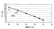
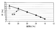
- the blade thickness ratio is 21 as a percentage of the blade thickness ratio which is a percentage of the value obtained by dividing the distance from the cord on the blade ventral side at the maximum blade thickness position by the cord length.
- % Position, ventral bulge YP is 9.0 ⁇ 0.6%, blade thickness ratio 24% position, ventral bulge YP 11.7 ⁇ 0.7%, blade thickness ratio 30% position, ventral
- the bulge YP is 16.7 ⁇ 1.2%, preferably 16.7 ⁇ 1.0%, more preferably 16.7 ⁇ 0.8%.
- the wind turbine blade according to the fourth aspect of the present invention includes a blade body portion whose cord length increases from the blade tip side to the blade root side, and the blade cross-sectional shape of the blade body portion is given by the ventral bulge YP. It was. This is based on the good correlation between the design lift coefficient and the ventral bulge YP. Thereby, it is possible to obtain a blade shape that satisfies a desired design lift coefficient.
- the present invention by defining the combination of the blade thickness ratio and the ventral bulge as described above, the change in the design lift coefficient of the blade cross section between the blade thickness ratio of 21% and 30% can be reduced, Desired aerodynamic characteristics can be obtained.
- the ventral bulge it is possible to provide a thin blade that achieves a high design lift coefficient, and to reduce the load that the wind turbine blade receives. Thereby, a windmill blade can be lengthened and a power generation amount can be improved as a result.
- the design peripheral speed ratio blade tip peripheral speed / inflow wind speed
- the Reynolds number is 3 to 10 million.
- the blade main body portion has a blade thickness ratio in the range of 21% to 35%, and the YP value and blade thickness at the blade thickness ratio of 21%. It is preferable to have YP obtained by an interpolation curve that passes through the value of YP at the position of 24% ratio and the value of YP at the position of 30% blade thickness ratio.
- the blade main body portion has a blade thickness ratio of 18%, YP is 6.3 ⁇ 0.5%, and the blade thickness ratio is 36. %,
- the YP is 21.4 ⁇ 2.0%, preferably 21.4 ⁇ 1.2%, more preferably 21.4 ⁇ 1.0%, and the blade thickness ratio is 42%. It may be 4 ⁇ 3.0%, preferably 25.4 ⁇ 2.0%, more preferably 25.4 ⁇ 1.5%.
- a wind turbine blade having a small change in the design lift coefficient over the region from the blade tip side (blade thickness ratio 18%) to the blade root side (blade thickness ratio 42%) is provided. be able to.
- the blade main body portion has a blade thickness ratio in the range of 18% to 42%, the YP value at the blade thickness ratio of 18%, the YP value at the blade thickness ratio of 21%, the blade The YP value at the 24% thickness ratio, the YP value at the 30% blade thickness position, the YP value at the 36% blade thickness position, and the YP value at the 42% blade thickness ratio position. It is preferable to have YP obtained by an interpolation curve that passes through the value.
- a wind turbine blade includes a blade main body portion in which a cord length decreases in a radial direction from a blade root side to a blade tip side, and an airfoil shape (blade cross section) at each radial position of the blade main body portion.
- the shape is characterized in that the dorsal shape is given as a shape expanded and contracted in the Y direction perpendicular to the chord direction.
- the dorsal shape of the airfoil shape (blade cross-sectional shape) at each radial position is a shape expanded and contracted in the Y direction, it is possible to realize a wind turbine blade that exhibits desired aerodynamic performance at each radial position.
- the term “expansion / contraction” is not limited as long as the desired aerodynamic characteristics are obtained.
- a wind turbine blade includes a blade main body portion in which a cord length decreases in a radial direction from a blade root side to a blade tip side, and an airfoil shape (blade cross section) at each radial position of the blade main body portion.
- the shape) is characterized in that the blade thickness distribution in the chord direction is given as a shape expanded and contracted in the Y direction.
- the blade thickness distribution of the airfoil shape (blade cross-sectional shape) at each radial position is expanded and contracted in the Y direction, it is possible to realize a wind turbine blade that exhibits desired aerodynamic performance at each radial position.
- the expansion / contraction ratio it is preferable to use a ratio of the blade thickness ratio obtained by dividing the maximum blade thickness by the cord length.
- a wind turbine blade according to a seventh aspect of the present invention includes a blade main body portion in which a cord length decreases in a radial direction from the blade root side to the blade tip side, and an airfoil shape (blade cross-section) at each radial position of the blade main body portion.
- the shape) is characterized in that the dorsal side shape is a shape expanded and contracted in the Y direction, and the blade thickness distribution in the chord direction is given as a shape expanded and contracted in the Y direction.
- the dorsal shape and blade thickness distribution of the airfoil shape (blade cross-sectional shape) at each radial position are given in a shape expanded and contracted in the Y direction, wind turbine blades that exhibit desired aerodynamic performance at each radial position Can be realized.
- the expansion / contraction ratio of the blade thickness distribution it is preferable to use a blade thickness ratio ratio obtained by dividing the maximum blade thickness by the cord length.
- a wind turbine blade includes a blade body portion in which a cord length decreases in a radial direction from a blade root side to a blade tip side, and an airfoil shape (blade cross section) at each radial position of the blade body portion.
- Shape is given as a shape in which the dorsal side shape is expanded and contracted in the Y direction, and the leading edge from the blade leading edge to the blade thickness maximum position of the blade shape (blade cross-sectional shape) at each radial position of the blade body
- the portion is provided with a shape in which the blade thickness distribution in the chord direction is expanded and contracted in the Y direction, and the ventral shape is determined from the blade thickness distribution and the dorsal shape.
- the dorsal shape of the airfoil shape (blade cross-sectional shape) at each radial position is given as a shape expanded and contracted in the Y direction, it is possible to realize a wind turbine blade that exhibits desired aerodynamic performance at each radial position. it can.
- the ventral side shape is defined as a shape in which the blade thickness distribution is expanded and contracted in the Y direction at the leading edge of the airfoil shape (blade cross-sectional shape) at each radial position, the wind turbine blade that exhibits desired aerodynamic performance Can be realized.
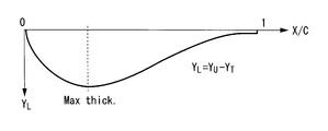
- ventral surface coordinates (distance from the chord position to the ventral shape) indicating the ventral shape are the correspondence obtained from the blade thickness distribution from the back coordinates of the dorsal shape (distance from the chord position to the dorsal shape). It can be obtained by reducing the blade thickness at the chord position to be performed (back surface coordinate-blade thickness). Further, the design lift coefficient can be optimized by arbitrarily designing the abdominal surface shape at the trailing edge portion on the trailing edge side from the maximum blade thickness position.
- the chord length position X / C obtained by dividing the distance X from the leading edge along the chord line by the cord length C is in the range of 0.28 to 0.32.
- the maximum blade thickness position where the blade thickness is maximum is provided, and the maximum camber position where the camber is maximum is provided within the range where the chord direction position X / C is 0.45 or more and 0.55 or less. It has a wing cross section.
- the chord direction position X / C is set within the range of 0.28 or more and 0.32 or less (more preferably 0.29 or more and 0.31 or less), and the maximum blade thickness position is arranged forward (front edge side) The arrangement) tends to improve the design lift coefficient, improve the maximum lift-drag ratio, and reduce the boundary layer thickness at the blade trailing edge as compared to the rear arrangement.
- the maximum lift-drag ratio is improved and the boundary layer thickness at the blade trailing edge is reduced compared to the rear camber.
- the maximum lift coefficient tends to decrease.
- the maximum lift coefficient tends to be improved, but the maximum lift / drag ratio tends to decrease.
- the chord direction position X / C is 0.45 or more and 0.55 or less so that the maximum camber position is intermediate between the front camber and the rear camber. It was determined to be.
- the design peripheral speed ratio (blade tip peripheral speed / inflow wind speed) is 6 or more (more preferably 8.0 or more and 9.0 or less), and the Reynolds number is 3 to 10 million.
- the camber distribution may be substantially symmetric in the chord direction about the maximum camber position.
- the blade cross section is provided at a wind turbine blade tip in which a blade thickness ratio obtained by dividing the maximum blade thickness by the cord length is in a range of 12% to 21%. It may be done.
- a high-performance and low-noise wind turbine blade can be realized by providing the blade cross section within a blade thickness ratio of 12% or more and 21% or less that functions as a main part for converting wind power into wind turbine blade rotation.
- a wind turbine generator includes a wind turbine blade described in any of the above, a rotor connected to a blade root side of the wind turbine blade, and rotated by the wind turbine blade, And a generator for converting the rotational force obtained by the rotor into an electrical output.
- the output can be increased by increasing the blade length.
- a wind turbine blade design method is a wind turbine blade design method including a blade main body portion in which a cord length increases from the blade tip side to the blade root side, on the tip side of the blade main body portion.
- the blade tip region in which the cord length gradually increases toward the blade root side is defined as a substantially constant first design lift coefficient, and the maximum cord length position that is the maximum cord length on the blade root side of the blade main body is defined as the first cord lift position.
- the first design lift coefficient is a second design lift coefficient larger than the design lift coefficient, and a transition region located between the blade tip region and the maximum cord length position is moved from the blade tip side to the blade root side.
- the design lift coefficient is gradually increased from the second design lift to the second design lift.
- the wind turbine blade includes a blade body portion in which the cord length increases from the blade tip side to the blade root side.
- the blade body portion includes a blade tip region in which the cord length increases toward the blade root side, and a blade root side.
- a maximum chord length position that is the maximum chord length, and a transition region located between the blade tip region and the maximum chord length position.
- the first design lift coefficient is determined as a practical upper limit that can be realized (for example, about 1.15 when the blade thickness ratio is about 18%).
- the size of the maximum code length is limited as a second design lift coefficient larger than the first design lift coefficient (see the above formula (3)).
- the second design lift coefficient By appropriately determining the second design lift coefficient, the upper limit value of the code length at the maximum code length position that is restricted for transportation reasons or the like is determined.
- the design lift coefficient gradually increases from the first design lift coefficient to the second design lift coefficient from the blade tip side toward the blade root side.
- a desired design lift coefficient is given to each of the blade tip region, the transition region, and the maximum code length position, and the design lift coefficient of the entire blade main body is determined. Since the combination is appropriately defined, desired aerodynamic characteristics can be exhibited even under the condition where the upper limit value of the cord length is limited on the blade root side. In particular, it is possible to improve the aerodynamic performance of the thick blade portion located on the blade root side with respect to the blade tip region.
- the design peripheral speed ratio (blade tip peripheral speed / inflow wind speed) is 6 or more (more preferably 8.0 or more and 9.0 or less), and the Reynolds number is 3 to 10 million.
- a wind turbine blade design method is a wind turbine blade design method including a blade main body portion in which a cord length increases from a blade tip side to a blade root side.
- Y125 is determined so as to satisfy a predetermined design lift coefficient, so that a wind turbine blade having desired aerodynamic characteristics can be realized.
- a wind turbine blade design method is a wind turbine blade design method including a blade body portion in which a cord length increases from a blade tip side to a blade root side.
- a design lift coefficient determination step for determining a predetermined design lift coefficient in the engine, and a distance from the blade back side code at the maximum blade thickness position so as to satisfy the design lift coefficient determined in the design lift coefficient determination step
- a YS determination step for determining a dorsal bulge YS which is a percentage of the value divided by the length.
- a wind turbine blade design method is the wind turbine blade design method including a blade main body portion in which the cord length increases from the blade tip side to the blade root side.
- a design lift coefficient determination step for determining a predetermined design lift coefficient in the step, and a distance from the blade ventral side code at the maximum blade thickness position so as to satisfy the design lift coefficient determined in the design lift coefficient determination step
- a YP determination step for determining a ventral bulge YP that is a percentage of the value divided by the length.
- a wind turbine blade design method is a wind turbine blade design method including a blade body portion in which a cord length is reduced in a radial direction from a blade root side to a blade tip side.
- the airfoil shape (blade cross-sectional shape) at each radial position of the portion is defined such that the dorsal shape is a shape expanded and contracted in the Y direction.
- the dorsal shape of the airfoil shape (blade cross-sectional shape) at each radial position is given as a shape expanded and contracted in the Y direction, it is possible to realize a wind turbine blade that exhibits desired aerodynamic performance at each radial position. it can.
- a wind turbine blade design method is a wind turbine blade design method including a blade main body portion in which a cord length decreases in a radial direction from a blade root side to a blade tip side.
- the airfoil shape (blade cross-sectional shape) at each radial position of the portion is defined such that the blade thickness distribution in the chord direction is expanded and contracted in the Y direction.
- the blade thickness distribution of the airfoil shape (blade cross-sectional shape) at each radial position is expanded and contracted in the Y direction, it is possible to realize a wind turbine blade that exhibits desired aerodynamic performance at each radial position.
- the expansion / contraction ratio it is preferable to use a ratio of the blade thickness ratio obtained by dividing the maximum blade thickness by the cord length.
- a wind turbine blade design method is a wind turbine blade design method including a blade main body portion in which a cord length decreases in a radial direction from a blade root side to a blade tip side.
- the blade shape (blade cross-sectional shape) at each radial position of the part is a shape in which the dorsal shape is expanded and contracted in the Y direction, and the blade thickness distribution in the chord direction is expanded and contracted in the Y direction. It is defined as follows.
- the dorsal shape of the airfoil shape (blade cross-sectional shape) and blade thickness distribution at each radial position are expanded and contracted in the Y direction, a wind turbine blade that exhibits desired aerodynamic performance at each radial position is realized. can do.
- As the expansion / contraction ratio of the blade thickness distribution it is preferable to use a blade thickness ratio ratio obtained by dividing the maximum blade thickness by the cord length.
- a wind turbine blade design method is a wind turbine blade design method including a blade main body portion in which a cord length decreases in a radial direction from a blade root side to a blade tip side.
- the airfoil shape (blade cross-sectional shape) at each radial position of the blade portion is defined so that the dorsal shape is expanded and contracted in the Y direction, and the airfoil shape (blade cross-section) at each radial position of the blade body portion Shape), the blade thickness distribution in the chord direction is expanded and contracted in the Y direction at the leading edge portion from the blade leading edge to the blade thickness maximum position, and the blade thickness distribution and the dorsal shape from the dorsal shape It is characterized by defining the shape.
- the dorsal shape of the airfoil shape (blade cross-sectional shape) at each radial position is a shape expanded and contracted in the Y direction, it is possible to realize a wind turbine blade that exhibits desired aerodynamic performance at each radial position.
- the ventral side shape is defined as a shape in which the blade thickness distribution is expanded and contracted in the Y direction at the leading edge of the airfoil shape (blade cross-sectional shape) at each radial position, the wind turbine blade that exhibits desired aerodynamic performance Can be realized.
- ventral surface coordinates (distance from the chord position to the ventral shape) indicating the ventral shape are the correspondence obtained from the blade thickness distribution from the back coordinates of the dorsal shape (distance from the chord position to the dorsal shape). It can be obtained by reducing the blade thickness at the chord position to be performed (back surface coordinate-blade thickness). Furthermore, the design lift coefficient can be optimized by allowing the abdominal surface shape to be arbitrarily designed at the trailing edge portion on the trailing edge side with respect to the maximum blade thickness position.
- a rear edge portion from the maximum blade thickness position to the blade trailing edge has a reference ventral shape determined from the back shape and the blade thickness distribution.
- it may be a ventral shape defined with a predetermined adjustment amount.
- the abdominal surface shape can be arbitrarily designed with a predetermined adjustment amount at the trailing edge portion on the trailing edge side from the maximum blade thickness position, the design lift coefficient can be optimized.
- the adjustment amount is zero at the maximum blade thickness position and the trailing edge of the blade, and the chord position where the first-order differential value in the chord direction of the chord direction of the ventral surface coordinates giving the ventral shape is zero. It may be given by a function defined by the quaternary formula.
- the chord direction position X / C obtained by dividing the distance X from the leading edge along the chord line by the cord length C is 0.28 or more and 0.32 or less.
- the maximum blade thickness position where the blade thickness is maximum is provided within the range of, and the maximum camber position where the camber is maximum is provided within the range where the chord direction position X / C is 0.45 or more and 0.55 or less. It is characterized by that.
- the chord direction position X / C is set within the range of 0.28 or more and 0.32 or less (more preferably 0.29 or more and 0.31 or less), and the maximum blade thickness position is arranged forward (front edge side) The arrangement) tends to improve the design lift coefficient, improve the maximum lift-drag ratio, and reduce the boundary layer thickness at the blade trailing edge as compared to the rear arrangement.
- the maximum lift-drag ratio is improved and the boundary layer thickness at the blade trailing edge is reduced compared to the rear camber.
- the maximum lift coefficient tends to decrease.
- the maximum lift coefficient tends to be improved, but the maximum lift / drag ratio tends to decrease.
- the chord direction position X / C is 0.45 or more and 0.55 or less so that the maximum camber position is intermediate between the front camber and the rear camber. It was determined to be.
- the design peripheral speed ratio (blade tip peripheral speed / inflow wind speed) is 6 or more (more preferably 8.0 or more and 9.0 or less), and the Reynolds number is 3 to 10 million.
- the desired design lift coefficient is given to each of the blade tip region, transition region, and maximum cord length position, and the combination of design lift coefficients is appropriately defined throughout the blade body. Even under conditions where the upper limit value of the length is limited, desired aerodynamic characteristics can be exhibited.
- Y125 having a correlation with the design lift coefficient is specified, a blade shape satisfying the desired design lift coefficient can be obtained. Therefore, it is possible to provide a thin blade that achieves a high design lift coefficient, and to reduce the load applied to the wind turbine blade. Thereby, a windmill blade can be lengthened and a power generation amount can be improved as a result.
- the dorsal shape and blade thickness distribution are defined so as to be expanded and contracted in the Y direction at each radial position (each blade thickness ratio), a windmill capable of achieving desired aerodynamic performance and increasing output Wings can be realized.
- the wind turbine blade according to the present embodiment is suitably used as a blade of a wind power generator.
- three wind turbine blades are provided, and each is connected to the rotor with an interval of about 120 °.
- the rotational diameter (blade diameter) of the wind turbine blade is 60 m or more, and the blade has a solidity of 0.2 to 0.6.
- the wind turbine blades may have a variable pitch or a fixed pitch.
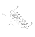
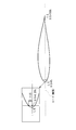
- the wind turbine blade 1 is a three-dimensional blade, and extends from the blade root 1a side, which is the rotation center side, toward the blade tip 1b side.
- the radial position (corresponding to the distance from the rotation center of the blade) of each blade thickness ratio (percentage of the maximum blade thickness divided by the cord length) Z (the longitudinal axis direction of the blade) at the position of the blade) represented by using a blade element section cut by a constant section.
- FIG. 1 shows that blade element cross sections cut at radial positions with blade thickness ratios of 18%, 21%, 24%, 30%, 36%, and 42% are used as the definition of the shape of the wind turbine blade. ing.
- a radial position r corresponding to the distance from the rotation center of the blade (or a dimensionless radial position r / R obtained by dividing the radial position by the blade radius). ) May be used.
- FIG. 2 the blade element cross section of FIG. 1 is projected onto the XY plane (a plane perpendicular to the Z axis).
- the right side is the blade leading edge and the left side is the blade trailing edge.
- the shape shown in the figure is called an airfoil.
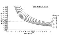
- FIG. 4 shows an explanatory diagram when designing the wind turbine blade 1 according to the present embodiment.
- the horizontal axis represents the dimensionless radius and the vertical axis represents the dimensionless code length.
- the dimensionless radius is a value (r / R) obtained by dividing the radial position r of the blade cross section from the rotation center by the blade radius R of the wind turbine blade 1 as described above.
- the blade radius is one half of the diameter (blade diameter) of the locus circle drawn by the tip of the blade as the wind turbine blade 1 rotates.
- the dimensionless code length is a value (c / R) obtained by dividing the code length c of the blade cross section by the blade radius R.
- FIG. 4 shows a plurality of curves (thin lines) in which the design lift coefficient CLdesign obtained from the above equation (3) is constant. Since the curve with the constant design lift coefficient CLdesign satisfies the above equation (3), the optimum code length (vertical axis) at the design peripheral speed ratio is given from the viewpoint of aerodynamic characteristics.
- the design peripheral speed ratio is 8.0 or more and 8.5 or less, and the Reynolds number is 3 million or more and 10 million or less.
- the wind turbine blade 1 includes a blade body portion 3 that increases in cord length from the blade tip 1b side to the blade root 1a side, as indicated by a thick line in FIG.
- the dimensionless radius of the wing body 3 is 0.2 or more and 0.95 or less.
- the blade body 3 is located on the blade tip 1b side, and the blade tip region 1c where the cord length gradually increases, the maximum cord position 1d located on the blade root 1a side and having the maximum cord length, and the blade tip region 1c. And a transition area 1e located between the maximum code length position 1d.
- the dimensionless radius of the blade tip region 1c is 0.5 or more and 0.95 or less
- the dimensionless radius of the maximum code length position 1d is (0.25 ⁇ 0.05)
- the transition region 1e is 0.2 or more (excluding 0.2) and less than 0.5.
- the blade tip region 1c has a substantially constant first design lift coefficient (1.15 in this embodiment).
- the first design lift coefficient of the blade tip region 1c is a practical upper limit that can be realized from the blade thickness ratio (for example, about 18%) of the blade tip region 1c that is a thin blade.
- the upper limit of the design lift coefficient should be large if the aerodynamic characteristics are taken into consideration, so that the warp will be increased in the case of thin blades. Is generated and the loss becomes large, so that the predetermined value is determined.
- desired aerodynamic characteristics can be exhibited in the blade tip region 1c that can receive a large amount of wind force and can expect an output. .
- the maximum code length position 1d is a second design lift coefficient (1.45 in the present embodiment) having a value larger than the first design lift coefficient.
- the second design lift coefficient is determined from the maximum code length that is limited by transportation reasons and the like. For example, as shown in FIG. 4, when the dimensionless maximum code length is limited to 0.08 due to the width of the road that transports the wind turbine blade 1, the design lift coefficient that takes this dimensionless maximum code length is From the dimensionless radius (0.25 ⁇ 0.05) given as the maximum code length position 1d, 1.45 is determined.
- the transition region 1e has a design lift coefficient that gradually increases from the first design lift coefficient (1.15) to the second design lift coefficient (1.45). That is, the blade root side of the blade tip region 1c having the first design lift coefficient and the maximum cord length position 1d having the second design lift coefficient were smoothly connected. As a result, even when the cord length is increased from the blade tip region 1c to the maximum cord length position 1d, the change range of the design lift coefficient can be kept small, so that the aerodynamic performance is not greatly impaired. In particular, it is possible to maintain a desired aerodynamic characteristic even in a thick wing portion that has not been considered in the past (a portion that is thicker than the blade tip region 1c; a region from the transition region 1e to the maximum cord length position 1d). it can.
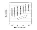
- FIGS. 5 and 6 are explanatory diagrams used when designing the wind turbine blade 1 shown in FIG. 4. Therefore, the vertical axis and horizontal axis are the same as those in FIG. 4, and the same design lift coefficient is used.
- a CLdesign curve is drawn.
- ⁇ Step 0> Under a predetermined design peripheral speed ratio (8.0 to 8.5 in the present embodiment), with a predetermined dimensionless radius, the performance optimization that satisfies the desired design lift coefficient is obtained from the above equation (3).
- the dimension code length is given. For example, as shown in FIG. 5, the dimensionless code length that gives the desired design lift coefficient 1.15 is 0.04 for the dimensionless radius position 0.6.
- the maximum code length position (the dimensionless radial position is about 0.2 to 0.3; in this embodiment, 0.24)
- the code length of 1d is a predetermined maximum value (the dimensionless code length is 0 for reasons of transportation). 0.06 to 0.085 or so; in this embodiment, 0.08).
- the design lift coefficient (second design lift coefficient) at the maximum cord length position 1d is determined (1.45 in the present embodiment).
- the cord length near the blade tip is about 0.85 to 0.95) is a practical upper limit of the design lift coefficient (in this embodiment, a thin blade with a blade thickness ratio of about 18%) In this case, it is defined by about 1.15; first design lift coefficient).
- the dimensionless code length is determined as follows. The transition region 1e in which the dimensionless radius position is 0.2 to 0.5 is between the first design lift coefficient (1.15) and the second design lift coefficient (1.45). The dimensionless code length is determined so that the design lift coefficient gradually increases from the side toward the blade root side. Thereby, in the blade body part 3 of the wind turbine blade 1, the combination of the dimensionless radial position and the design lift coefficient is defined.
- the thick line shown in FIG. 6 indicates the median design code length. Actually, the dimensionless code length at each dimensionless radius is determined within a predetermined range, and the area is shown in FIG. In frame 5.
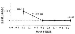
- FIG. 7A, 7B, and 7C show the distribution of the design lift coefficient for each dimensionless radial position for the wind turbine blade 1 that is shaped as described above.
- the blade tip region 1c in which the dimensionless radius position is 0.5 or more and 0.95 or less is set to a range of X ⁇ 0.10, where X is the median value of the first design lift coefficient.
- the second design lift coefficient at the maximum code length position 1d where the dimensionless radius position is (0.25 ⁇ 0.05) is X + 0.3 ⁇ 0.2.
- the transition region 1e in which the dimensionless radius position is 0.2 or more (excluding 0.2) and less than 0.5 is the blade root side end of the blade tip region 1c (position where the dimensionless radius is 0.5).
- the design lift coefficient at the center position (the position where the dimensionless radius is 0.35 in the figure) between the maximum cord length position 1d and X1 is 0.1 + 0.15 ⁇ 0.15.
- FIG. 7B shows an example in which the range of the design lift coefficient is narrower than that in FIG. 7A. That is, the blade tip region 1c in which the dimensionless radial position is 0.5 or more and 0.95 or less is set to a range of X ⁇ 0.05 when X is the median value of the first design lift coefficient. .
- the second design lift coefficient at the maximum code length position 1d where the dimensionless radius position is (0.25 ⁇ 0.05) is X + 0.3 ⁇ 0.1.
- the transition region 1e in which the dimensionless radius position is 0.2 or more (excluding 0.2) and less than 0.5 is the blade root side end of the blade tip region 1c (position where the dimensionless radius is 0.5).
- the design lift coefficient at the center position (the position where the dimensionless radius is 0.35 in the figure) between the maximum cord length position 1d and X1 is 0.1 + 0.075 ⁇ 0.075.
- FIG. 7C shows an example in which a specific design lift coefficient is given. That is, the blade tip region 1c in which the dimensionless radial position is 0.5 or more and 0.95 or less has a first design lift coefficient of 1.15 ⁇ 0.05.
- the second design lift coefficient at the maximum code length position 1d where the dimensionless radius position is (0.25 ⁇ 0.05) is 1.45 ⁇ 0.1.
- the transition region 1e in which the dimensionless radius position is 0.2 or more (excluding 0.2) and less than 0.5 is the blade root side end of the blade tip region 1c (position where the dimensionless radius is 0.5).
- the maximum code length position 1d is 1.30 ⁇ 0.075 in the design lift coefficient at the center position (the position where the dimensionless radius is 0.35 in the figure).
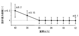
- FIGS. 8A, 8B and 8C show the distribution of the design lift coefficient with respect to each blade thickness ratio for the wind turbine blade 1 whose shape is determined as shown in FIGS. 4 to 6.
- the horizontal axis is shown as a dimensionless radius, but in FIGS. 8A, 8B and 8C, the horizontal axis is shown as a blade thickness ratio.
- the blade thickness ratio is a value obtained by dividing the maximum value of the blade thickness by the cord length in percentage.
- the blade tip region 1c in which the blade thickness ratio is 12% or more and 30 or less is in the range of X ⁇ 0.10, where X is the median value of the first design lift coefficient.
- the second design lift coefficient at the maximum cord length position 1d where the blade thickness ratio is 42% is X + 0.3 ⁇ 0.2.
- the transition region 1e in which the blade thickness ratio is 30% or more (not including 30%) and less than 42% is the blade root side end of the blade tip region 1c (position where the blade thickness ratio is 30%) and the maximum cord length position
- the design lift coefficient at the center position between 1d is X + 0.15 ⁇ 0.15.
- FIG. 8B shows an example in which the range of the design lift coefficient is narrower than that in FIG. 8A. That is, the blade tip region 1c having a blade thickness ratio of 12% or more and 30 or less is in a range of X ⁇ 0.05, where X is the median value of the first design lift coefficient.
- the second design lift coefficient at the maximum cord length position 1d where the blade thickness ratio is 42% is X + 0.3 ⁇ 0.1.
- the transition region 1e in which the blade thickness ratio is 30% or more (not including 30%) and less than 42% is the blade root side end of the blade tip region 1c (position where the blade thickness ratio is 30%) and the maximum cord length position
- the design lift coefficient at the center position between 1d is X + 0.15 ⁇ 0.075.
- FIG. 8C shows an example in which a specific design lift coefficient is given. That is, in the blade tip region 1c in which the blade thickness ratio is 12% or more and 30 or less, the first design lift coefficient is in the range of 1.15 ⁇ 0.05.
- the second design lift coefficient at the maximum cord length position 1d where the blade thickness ratio is 42% is 1.45 ⁇ 0.1.
- the transition region 1e in which the blade thickness ratio is 30% or more (not including 30%) and less than 42% is the blade root side end of the blade tip region 1c (position where the blade thickness ratio is 30%) and the maximum cord length position
- the design lift coefficient at the center position between 1d is 1.30 ⁇ 0.075.
- the shape of the wind turbine blade 1 that realizes this design lift coefficient is defined.
- a method will be described. Specifically, the airfoil at each blade thickness position is defined by determining Y125 indicating the distance from the chord on the back side of the blade tip (Y125 determination step). As shown in FIG. 9, Y125 is obtained from the cord on the blade back side at the 1.25% position when the cord length position of the blade leading edge is 0% and the cord length position of the blade trailing edge is 100%. Is the percentage of the value obtained by dividing the distance by the code length.
- FIGS. 10A, 10B and 10C show the distribution of Y125 with respect to the blade thickness ratio.
- Y125 in FIGS. 10A, 10B, and 10C is defined as shown in the table below. That is, Y125 is defined within the range (a), preferably defined within the range (b), and more preferably defined within the range (c).
- the wind turbine blade 1 has Y125 obtained by an interpolation curve that passes through Y125 at each blade thickness ratio shown in the above table in each blade section.
- FIG. 10A, FIG. 10B, and FIG. 10C the Y125 value of the windmill blade obtained on the basis of the conventional NACA blade is plotted as a square mark as a comparative example for this embodiment.
- the windmill blade concerning this embodiment has Y125 different from the conventional windmill blade.
- the blade shape in the wind turbine is determined almost uniquely from the blade leading edge to the maximum blade thickness position.
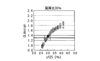
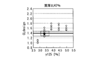
- FIG. 11A to FIG. 11E show data as a basis for obtaining a desired design lift coefficient by Y125.
- 11A to 11E show the results when the blade thickness ratio is 21%, 24%, 30%, 36%, and 42%, respectively. These figures are obtained as a result of changing Y125 by numerical simulation. As shown in each figure, it can be seen that there is a strong correlation between the design lift coefficient and Y125.
- the design lift coefficient optimally determined as described above is realized, the maximum lift coefficient is improved, the maximum lift-drag ratio is improved, and the turbulent boundary layer thickness at the blade trailing edge is reduced.
- FIG. 12 shows an airfoil according to the present embodiment.
- the airfoil is normalized with respect to the blade cross-section at each blade thickness ratio of the wind turbine blade 1 using a cord length C that is a length on the chord line 7 passing from the leading edge 6 to the trailing edge 4.
- the wind inflow angle is represented by ⁇
- the drag coefficient is represented by CD
- the lift coefficient is represented by CL.
- a turbulent boundary layer 5 develops from the maximum blade thickness position 2 on the back side to the trailing edge 4. Aerodynamic noise is caused by vortices in the boundary layer discharged from the turbulent boundary layer 5. Therefore, aerodynamic noise can be reduced by reducing the turbulent boundary layer thickness DSTAR at the trailing edge 4.
- the airfoil shown in the figure is provided in a range where the blade thickness ratio is 12% or more and 21% or less.
- the range of the blade thickness ratio is defined as a range that functions as a main part that converts wind power into rotation of a wind turbine blade.
- the maximum blade thickness position 2 is provided in the range where the chord direction position X / C is 0.28 or more and 0.32 or less (more preferably 0.29 or more and 0.31 or less).
- the maximum camber position where the camber is maximum is provided in the range where the chord direction position X / C is 0.45 or more and 0.55 or less.
- the camber distribution is substantially symmetrical in the chord direction about the maximum camber position.
- each parameter characterizing the performance of the wind turbine blade is shown with respect to the wind inflow angle ⁇ .
- FIG. 13A shows a change in the lift coefficient CL with respect to the wind inflow angle ⁇ .
- the lift coefficient CL increases as the wind inflow angle ⁇ increases, and decreases after showing the maximum lift coefficient CLmax, which is the maximum value.
- the maximum lift coefficient CLmax is preferably as large as possible in relation to performance improvement in a high wind speed region and prevention of stall caused by fluctuation or turbulence of inflow air.
- the maximum lift coefficient CLmax is a parameter that affects the blade aerodynamic performance in the transition state from when the wind turbine reaches the maximum rotational speed until it reaches the rated output.
- the design lift coefficient CLdesign is desired to have a large value in order to exhibit high performance with an elongated blade such as a wind turbine blade of a large wind turbine.
- FIG. 13B shows the change in the lift-drag ratio with respect to the wind inflow angle ⁇ .
- the lift / drag ratio L / D increases as the wind inflow angle ⁇ increases, and decreases after the maximum lift / drag ratio L / Cmax is shown.
- the maximum lift / drag ratio L / Dmax is a parameter that affects the aerodynamic performance of the blade when the wind turbine is operating at a variable speed (design point), and it is desired to have a large value.
- FIG. 13C shows the position change of the transition position XTR with respect to the wind inflow angle ⁇ .
- the transition position XTR when the wind inflow angle ⁇ is small, the transition position XTR is located approximately at the center of the chord, and when the wind inflow angle ⁇ exceeds a predetermined value, it moves toward the blade leading edge (LE) side. And move. That is, if the transition position XTR is positioned forward (front edge side), it means that roughness characteristics and stall characteristics are improved.
- FIG. 13D shows the change in the boundary layer thickness (exclusion thickness) DSTAR at the trailing edge of the blade with respect to the wind inflow angle ⁇ .
- the boundary layer thickness DSTAR increases as the wind inflow angle ⁇ increases. Since this boundary layer thickness DSTAR is considered to be the main cause of the generation of aerodynamic noise, it is desired to make it smaller.
- the maximum blade thickness position is improved in the design lift coefficient CLdesign and the maximum lift-drag ratio compared to the rear position by placing it at the front position (the leading edge side of the center position of the chord). This tends to improve L / Dmax and reduce the boundary layer thickness DSTAR. Therefore, it is preferable to provide the maximum blade thickness position within the range where the chord direction position X / C is 0.28 or more and 0.32 or less (more preferably 0.29 or more and 0.31 or less).
- the maximum camber position tends to improve the maximum lift / drag ratio L / Dmax and reduce the boundary layer thickness DSTAR compared to the rear camber.
- the maximum lift coefficient CLmax tends to decrease.
- the rear camber tends to increase the maximum lift coefficient CLmax, but tends to decrease the maximum lift / drag ratio L / Dmax.
- the chord direction position X / C is 0.45 or more and 0.55 or less so that the maximum camber position is intermediate between the front camber and the rear camber.
- the camber distribution is substantially symmetric in the chord direction about the maximum camber position.
- the design lift coefficient CLdesign, the maximum lift coefficient CLmax, and the maximum lift / drag ratio L / Dmax tended to improve.
- the lower limit of the chord direction position X / C is preferably 0.28.
- the chord direction position X / C of the maximum camber position is set to 0.45 or more and 0.55 or less, and the camber distribution is substantially symmetrical in the chord direction about the maximum camber position. It is shown that it is preferable to do so.
- FIGS. 14A and 14B the results obtained by the numerical simulation under a plurality of conditions are plotted in the same figure.
- FIG. 15A it is shown that the maximum lift coefficient CLmax increases as the maximum camber position changes from the trailing edge side to the leading edge side. That is, the front camber is preferable from the viewpoint of the maximum lift coefficient CLmax.
- FIG. 15A it is shown that the maximum lift coefficient CLmax increases as the maximum camber position changes from the trailing edge side to the leading edge side. That is, the front camber is preferable from the viewpoint of the maximum lift coefficient CLmax.
- FIG. 15A it is shown that the maximum lift coefficient CLmax increases as the maximum camber position changes from the trailing edge side to the leading edge side. That is, the front camber is preferable from
- the maximum lift / drag ratio L / Dmax increases as the maximum camber position changes from the front edge side to the rear edge side. That is, from the viewpoint of the maximum lift / drag ratio L / Dmax, the rear camber is preferable. Therefore, in order to satisfy both the high maximum lift coefficient CLmax and the maximum lift / drag ratio L / Dmax, the chord direction position X / C of the maximum camber position is not less than 0.45 and not more than 0.55 (preferably Is preferably 0.5).
- the following operational effects are obtained. Since a desired design lift coefficient is given to each of the blade tip region 1c, the transition region 1e, and the maximum cord length position 1d, and the combination of the design lift coefficients is appropriately defined over the entire blade body 3, the blade Even under the condition where the upper limit of the cord length is limited on the root side, desired aerodynamic characteristics can be exhibited. In particular, it is possible to improve the aerodynamic performance of the thick blade portion (the transition region 1e and the maximum cord length position 1d) located on the blade root side with respect to the blade tip region 1c. In addition, since Y125 having a correlation with the design lift coefficient is defined, a blade shape satisfying a desired design lift coefficient can be obtained.
- the maximum blade thickness position is located in the front
- the maximum camber position is located in the center of the chord direction
- the camber distribution is symmetrical with respect to the chord direction with the maximum camber position at the center.
- Y125 indicating the distance from the chord on the back side of the blade tip is determined in the first embodiment, whereas the blade shape is determined using the backside bulge YS of the blade. It is different. Since other points are the same as those of the first embodiment, description thereof will be omitted.
- a method of defining the shape of the wind turbine blade 1 that realizes this design lift coefficient explain. Specifically, by determining the wing dorsal bulge YS (YS determination step), the airfoil at each blade thickness position is defined. As shown in FIG. 16, YS is a percentage of a value obtained by dividing the distance from the chord (blade chord) on the blade back side at the maximum blade thickness position by the chord length.
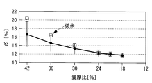
- FIGS. 17A, 17B, and 17C the distribution of the back bulge YS with respect to the blade thickness ratio is shown.
- YS in FIGS. 17A, 17B, and 17C is defined as shown in the table below. That is, the back bulge YS is defined within the range (a), preferably defined within the range (b), and more preferably defined within the range (c).
- the wind turbine blade 1 has a back-side bulge YS obtained by an interpolation curve that passes through the back-side bulge YS at each blade thickness ratio shown in the above table in each blade cross section.
- FIG. 17A, FIG. 17B, and FIG. 17C show, as a comparative example with respect to the present embodiment, a dorsal bulge YS of a wind turbine blade obtained based on a conventional NACA blade by square marks.
- the wind turbine blade according to the present embodiment has a different back-side bulge YS from the conventional wind turbine blade.
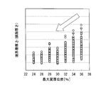
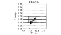
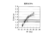
- 18A to 18E show data that provides a basis for obtaining a desired design lift coefficient by the back bulge YS.
- 18A to 18E show the results when the blade thickness ratio is 21%, 24%, 30%, 36%, and 42%, respectively. These figures are obtained as a result of changing the back bulge YS by numerical simulation. As shown in each figure, it can be seen that there is a strong correlation between the design lift coefficient and the back bulge YS.
- the following operational effects are obtained. Since the dorsal bulge YS correlated with the design lift coefficient is defined, a blade shape satisfying the desired design lift coefficient can be obtained. Therefore, it is possible to provide a thin blade that achieves a high design lift coefficient, and to reduce the load applied to the wind turbine blade. Thereby, a windmill blade can be lengthened and a power generation amount can be improved as a result.
- This embodiment is different in that the blade shape is determined using the ventral bulge YP, while the blade shape is determined using the dorsal bulge YS in the second embodiment. Since other points are the same as those of the first embodiment, description thereof will be omitted.
- a method of defining the shape of the wind turbine blade 1 that realizes this design lift coefficient explain. More specifically, by determining the ventral bulge YP of the wing (YP determination step), the wing shape at each blade thickness position is defined. As shown in FIG. 16, YP is a percentage of a value obtained by dividing the distance from the chord on the blade side at the maximum blade thickness position by the chord length.
- FIG. 19A, 19B, and 19C show the distribution of the ventral bulge YP with respect to the blade thickness ratio.
- YP in FIG. 19A, FIG. 19B and FIG. 19C is defined as shown in the table below. That is, the ventral bulge YP is defined within the range (a), preferably defined within the range (b), and more preferably defined within the range (c).
- the wind turbine blade 1 is a ventral bulge YP obtained by an interpolation curve passing through the ventral bulge YP at each blade thickness ratio shown in the above table.
- FIG. 19A, FIG. 19B, and FIG. 19C show, as a comparative example with respect to the present embodiment, a dorsal bulge YS of a wind turbine blade obtained based on a conventional NACA blade by square marks.
- the wind turbine blade according to the present embodiment has a different back-side bulge YS from the conventional wind turbine blade.
- 20A to 20E show data that provides a basis for obtaining a desired design lift coefficient by the ventral bulge YP.
- 20A to 20E show the results when the blade thickness ratio is 21%, 24%, 30%, 36%, and 42%, respectively. These figures are obtained as a result of changing the ventral bulge YP by numerical simulation. As shown in each figure, it can be seen that there is a strong correlation between the design lift coefficient and the ventral bulge YP.
- the following operational effects are obtained. Since the dorsal bulge YS correlated with the design lift coefficient is defined, a blade shape satisfying the desired design lift coefficient can be obtained. Therefore, it is possible to provide a thin blade that achieves a high design lift coefficient, and to reduce the load applied to the wind turbine blade. Thereby, a windmill blade can be lengthened and a power generation amount can be improved as a result.
- FIG. 21A to 21D show the effects of the above-described first to third embodiments.
- the A wing is a reference wing to be compared, and the design lift coefficient at the wing tip is about 0.8, and the design lift coefficient is not optimized in the blade length (radius) direction.
- B wing is a design lift coefficient 40% higher than that of A wing
- C wing is equivalent to this embodiment, and the design lift coefficient is further increased in the blade length (radius) direction with respect to B wing. It has been optimized.
- the design lift coefficient is increased as in the B blade, the optimum cord length can be reduced by 30% as shown in FIG. 21B, whereby the blade diameter can be extended by 7% as shown in FIG.
- the power generation amount is increased by 6.5% as shown in FIG. 21D. Since the design lift coefficient in the blade C is optimized in the blade length direction, the blade efficiency is further improved by 2% compared to the blade B, and the power generation amount is 1% higher than the blade B as shown in FIG. 21D (A 7.5% to the wing).
- Y125 mentioned above and the back side swell YS and the ventral side swell YP of each embodiment pass Y125 shown in Table 1 to Table 3, and the back side swell YS and the ventral side swell YP in each phrase blade thickness ratio.
- the wind turbine blade of the present invention is not limited to this, and the values of the backside bulge YS and the ventral side bulge YP of Tables 1 and 2 when the blade thickness ratio is 21% to 35%. It only needs to be a passing interpolation curve. This is because the characteristics of the wind turbine are mainly determined within the range of the blade thickness ratio.
- the design peripheral speed ratio is set to 8.0 or more and 8.5 or less.
- the present invention is not limited to this.
- the design peripheral speed ratio is 6.0 or more and 9.0 or less. It can be applied even if it exists.
- the blade tip region 1c, the transition region 1e, and the maximum code length position are not limited to the dimensionless radial position and blade thickness ratio range shown in the present embodiment, but in a range where the effects of the present invention are exhibited. It can be changed as appropriate.
- This embodiment is different from the above-described embodiment in that the dorsal shape and the blade thickness distribution are determined so as to be expanded and contracted in the Y direction at each radial position (each blade thickness ratio). Since other points are the same as those of the first embodiment, description thereof will be omitted.
- a desired design lift coefficient is determined at each blade thickness position (or radial position) as shown in FIG. 8C, a method of defining the shape of the wind turbine blade 1 that realizes this design lift coefficient will be described.
- This embodiment is particularly effective when defining the blade shape (blade cross-sectional shape) at each blade thickness position so as to have substantially the same design lift coefficient.
- the airfoil shape (blade cross-sectional shape) at each blade thickness position (radial position) of the blade main body 3 is defined such that the dorsal shape thereof is a shape expanded and contracted in the Y direction.
- This method for determining the dorsal shape is shown in FIG. In FIG. 22, the horizontal axis is the chord direction position X / C normalized by dividing the distance from the leading edge by the chord length C, and the vertical axis represents the distance from the chord line (horizontal axis).
- the coordinates Yu are normalized by dividing by the length C. Note that FIG. 23 to FIG. 25 to be described later have a normalized coordinate system divided by the code length C as in FIG. As shown in FIG.
- FIG. 23 shows a method for determining the blade thickness distribution.
- the blade shape (blade cross-sectional shape) at each blade thickness position (radial position) of the blade body 3 is defined so that the blade thickness distribution is a shape expanded and contracted in the Y direction. That is, as shown in FIG. 23, when the blade thickness distribution defined by the blade thickness Y T1 corresponding to the chord position (X / C) is the reference blade thickness distribution, the second blade thickness at different blade thickness positions is used.
- the distribution is expressed as follows using the blade thickness Y T 2.
- Y T 2 Y T 1 ⁇ (xx2 / xx1) (5)
- (xx2 / xx1) is the expansion / contraction ratio
- the ratio of the blade thickness ratio xx2 of the second blade thickness distribution to the blade thickness ratio xx1 of the reference blade thickness distribution is favorably used.
- the blade thickness distribution of the blade shape (blade cross-sectional shape) at each blade thickness position is expanded and contracted in the Y direction, so aerodynamic performance equivalent to the reference blade thickness distribution at each blade thickness position Can be defined.
- FIG. 24 shows a method for determining the ventral shape of the airfoil shape (wing cross-sectional shape).
- Leading edge from the leading edge to the maximum blade thickness position (Max thick) is determined from the back shape Yu and blade thickness distribution Y T determined by the above-mentioned equations (4) and (5), the ventral shape To do.
- Y L Yu ⁇ Y T (6)
- the ventral shape obtained by the above formula (6) may be used as the ventral shape at the trailing edge from the blade thickness maximum position to the blade trailing edge.
- the ventral side shape of the rear edge is defined as the ventral side shape obtained by the above equation (6) with the reference ventral side shape having a predetermined adjustment amount.
- the back side shape and blade thickness distribution of the airfoil shape (blade cross-sectional shape) at each blade thickness position (radial position) are made to be expanded and contracted in the Y direction.
- an airfoil shape (blade cross-sectional shape) having a desired design lift coefficient can be provided in the radial direction of the wind turbine blade, and as a result, the performance of the wind turbine blade can be improved.
- a wind turbine blade whose blade shape (blade cross-sectional shape) is expanded and contracted in the Y direction can be provided, the continuity of the blade shape is improved, and the yield during blade manufacturing can be improved.
Abstract
Description
風力発電装置の発電出力は、軸端出力(翼が発生する出力)と、変換効率(軸受や発電機などの効率)との積で表される。また、軸端出力は次式で表され、翼効率が高く、翼直径が大きい翼であれば、発電量が向上する。
軸端出力=1/2×空気密度×風速3×翼効率×π×(翼直径/2)2
一方、翼直径はその自乗で出力に影響を持つため、発電量向上のためには翼直径の拡大が効果的である。しかし、翼直径の拡大は空力荷重(流入方向に作用するスラスト力および翼根に伝わるモーメント)の増大に繋がるため、ロータヘッド、ナセル、タワーなどの機器の大型化や重量増大、ひいてはコスト増に繋がる懸念・傾向がある。したがって、翼の空力荷重の増大を抑えながら長翼化する技術が必須とされる。荷重増大の問題を避けるため、空力的(翼形状的)に考えられる方法としては、コード長(翼弦長)をより短くして(即ち、アスペクト比をより大きくして、又はソリディティをより小さくして)、翼投影面積を減少させて空力荷重を低減させる手法が考えられる。
ここで、アスペクト比およびソリディティは、下式で表される。
アスペクト比=翼長2/翼投影面積 (1)
ソリディティ=全翼投影面積/翼掃過面積
=(翼枚数×平均コード長)/(π×(翼直径/2)2) (2)
Copt/R×λ2×CLdesign×r/R≒16/9×π/n (3)
ここで、Coptは最適コード長,R(翼半径)は翼直径の2分の1,λは設計周速比,CLdesignは設計揚力係数,rは翼断面の半径位置,nは翼枚数である。
設計周速比は、翼端周速/無限上流風速である。設計揚力係数は、翼型(翼断面)の揚抗比(揚力/抗力)が最大となる迎角における揚力係数であり、翼型(翼断面)の(空力)形状と流入条件(レイノルズ数)によって決まる。
図26には、本明細書にて用いるレイノルズ数の定義が示されている。同図に示されているように、風車におけるレイノルズ数は、所定の回転数で回転する翼の所定断面A-Aにおける相対風速度を考慮したものであり、下式にて表される。
レイノルズ数=空気密度×翼断面への相対風速度×翼断面のコード長/空気の粘性係数
1.設計揚力係数が高い
2.設計揚力係数の「組合せ」が最適化されている
ここで、設計揚力係数の「組合せ」とは、一つの風車翼に適用される異なる翼厚比(翼厚の最大値をコード長で除した値の百分率)からなる一連の翼型群(Airfoil series/family/set)がそれぞれ持つ設計揚力係数の組合せを言う。例えば、風車に適用される翼型の翼厚比としては、12,15,18,21,24,30,36,42%の組合せが挙げられる。
しかし、背側膨らみYSや腹側膨らみYPと設計揚力係数との関係については何ら検討されていない。
これに対して、上記特許文献1には、風車出力の観点から適切な設計揚力係数の組み合わせについて開示されているが、翼厚比が30%を超える翼根側についても設計揚力係数が1.10~1.25の範囲とされており、これではコード長が過大となり風車翼の輸送が困難となる。
したがって、翼先端領域よりも翼根側に位置する厚翼部(先端領域よりも厚翼となる部位;遷移領域から最大コード長位置にかけての領域)での空力性能の向上の余地がある。
一方、風車翼が所望の空力性能を発揮したとしても、これと同時に風車翼の空力騒音についても考慮されなければ、風車を設置した周囲環境に悪影響を及ぼすことになる。
本発明の第1の態様にかかる風車翼は、翼先端側から翼根側にかけてコード長が増大する翼本体部を備え、該翼本体部は、その先端側にて、略一定の第1設計揚力係数とされた状態で、翼根側に向けてコード長が漸次増大する翼先端領域と、翼根側の最大コード長となる位置にて、前記第1設計揚力係数よりも大きい第2設計揚力係数を有する最大コード長位置と、前記翼先端領域と前記最大コード長位置との間に位置する遷移領域と、を有し、該遷移領域の設計揚力係数は、翼先端側から翼根側に向かって、前記第1設計揚力係数から前記第2設計揚力係へと漸次増大させられていることを特徴とする。
風力を大きく受けて出力が期待できる翼先端領域では、略一定の第1設計揚力係数として、翼先端領域全体で所望の空力特性を発揮させることとした。第1設計揚力係数は、実現可能な実質的な上限値(例えば翼厚比18%程度の場合に1.15程度)として定められる。
一方、最大コード長位置では、第1設計揚力係数よりも大きい第2設計揚力係数として、最大コード長の大きさを制限することとした(上式(3)参照)。この第2設計揚力係数を適宜定めることによって、輸送上の理由等によって制限される最大コード長位置のコード長の上限値が決定される。
そして、遷移領域では、翼先端側から翼根側に向かって、第1設計揚力係数から第2設計揚力係数へと漸次増大する設計揚力係数をもたせることとした。これにより、翼先端領域から最大コード長位置までコード長を増大させる場合であっても、設計揚力係数の変化幅を小さく止めることができるので、空力性能を大きく損なうことがない。特に、従来では考慮されていなかった厚翼部(翼先端領域に比べて厚翼となる部位;遷移領域から最大コード長位置にかけての領域)においても所望の空力特性を維持することができる。
このように、本発明の風車翼は、翼先端領域、遷移領域および最大コード長位置のそれぞれに対して所望の設計揚力係数を与え、翼本体部の全体にわたって設計揚力係数の組み合わせを適切に規定することとしたので、翼根側にコード長の上限値が制限された条件下であっても、所望の空力特性を発揮させることができる。特に、翼先端領域よりも翼根側に位置する厚翼部の空力性能を向上させることができる。
なお、好ましくは、設計周速比(翼端周速/流入風速)は6以上(より好ましくは8.0以上9.0以下)、レイノルズ数は300万以上1000万以下とされる。
特に、本発明では、翼厚比とY125との組み合わせを上記のように規定することにより、翼厚比が21%から30%までの間の翼断面の設計揚力係数の変化を小さくでき、所望の空力特性を得ることができる。
また、Y125を規定することにより高い設計揚力係数を実現した細翼を提供することができ、風車翼が受ける荷重を低減することができる。これにより、風車翼を長翼化することができ、結果的に発電量を向上させることができる。
なお、好ましくは、設計周速比(翼端周速/流入風速)は6以上(より好ましくは8.0以上9.0以下)、レイノルズ数は300万以上1000万以下とされる。
特に、本発明では、翼厚比と背側膨らみとの組み合わせを上記のように規定することにより、翼厚比が21%から30%までの間の翼断面の設計揚力係数の変化を小さくでき、所望の空力特性を得ることができる。
また、背側膨らみを規定することにより高い設計揚力係数を実現した細翼を提供することができ、風車翼が受ける荷重を低減することができる。これにより、風車翼を長翼化することができ、結果的に発電量を向上させることができる。
なお、好ましくは、設計周速比(翼端周速/流入風速)は6以上(より好ましくは8.0以上9.0以下)、レイノルズ数は300万以上1000万以下とされる。
特に、本発明では、翼厚比と腹側膨らみとの組み合わせを上記のように規定することにより、翼厚比が21%から30%までの間の翼断面の設計揚力係数の変化を小さくでき、所望の空力特性を得ることができる。
また、腹側膨らみを規定することにより高い設計揚力係数を実現した細翼を提供することができ、風車翼が受ける荷重を低減することができる。これにより、風車翼を長翼化することができ、結果的に発電量を向上させることができる。
なお、好ましくは、設計周速比(翼端周速/流入風速)は6以上(より好ましくは8.0以上9.0以下)、レイノルズ数は300万以上1000万以下とされる。
なお、本発明における「伸縮」とは、所望の空力特性が得られる範囲において実質的に伸縮されていれば良い。
なお、伸縮比としては、最大翼厚をコード長で除した翼厚比の比を用いることが好ましい。
なお、翼厚分布の伸縮比としては、最大翼厚をコード長で除した翼厚比の比を用いることが好ましい。
また、各半径位置における翼型形状(翼断面形状)の前縁部にて翼厚分布をY方向に伸縮された形状として腹側形状を定めているので、所望の空力性能を発揮する風車翼を実現することができる。なお、腹側形状を示す腹面座標(翼弦位置から腹側形状までの距離)は、背側形状の背面座標(翼弦位置から背側形状までの距離)から、翼厚分布から得られる対応する翼弦位置の翼厚を減じること(背面座標-翼厚)によって得ることができる。
さらに、最大翼厚位置よりも後縁側の後縁部では、任意に腹面形状を任意に設計できるようにして、設計揚力係数の最適化を図ることができる。
翼弦方向位置X/Cが0.28以上0.32以下(より好ましくは0.29以上0.31以下)の範囲内に最大翼厚位置を設け、最大翼厚位置を前方配置(前縁側配置)とすることにより、後方配置に比べて、設計揚力係数の向上、最大揚抗比の向上、及び、翼後縁における境界層厚さの低減の傾向となる。
また、最大キャンバ位置が翼弦中央よりも前縁側に位置する前方キャンバの場合、後方キャンバに比べて、最大揚抗比の向上、及び、翼後縁における境界層厚さの低減の傾向となるが、最大揚力係数の低下の傾向となる。一方、後方キャンバの場合、最大揚力係数の向上の傾向の傾向となるが、最大揚抗比の低下の傾向となる。このように、前方キャンバと後方キャンバではトレードオフの関係になるので、前方キャンバと後方キャンバの中間となるように最大キャンバ位置を翼弦方向位置X/Cが0.45以上0.55以下となるように定めた。
以上の組み合わせにより、高性能かつ低騒音の風車翼を実現することができる。
なお、好ましくは、設計周速比(翼端周速/流入風速)は6以上(より好ましくは8.0以上9.0以下)、レイノルズ数は300万以上1000万以下とされる。
風力を大きく受けて出力が期待できる翼先端領域では、略一定の第1設計揚力係数として、翼先端領域全体で所望の空力特性を発揮させることとした。第1設計揚力係数は、実現可能な実質的な上限値(例えば翼厚比18%程度の場合に1.15程度)として定められる。
一方、最大コード長位置では、第1設計揚力係数よりも大きい第2設計揚力係数として、最大コード長の大きさを制限することとした(上式(3)参照)。この第2設計揚力係数を適宜定めることによって、輸送上の理由等によって制限される最大コード長位置のコード長の上限値が決定される。
そして、遷移領域では、翼先端側から翼根側に向かって、第1設計揚力係数から第2設計揚力係数へと漸次増大する設計揚力係数をもたせることとした。これにより、翼先端領域から最大コード長位置までコード長を増大させる場合であっても、設計揚力係数の変化幅を小さく止めることができるので、空力性能を大きく損なうことがない。特に、従来では考慮されていなかった厚翼部(翼先端領域に比べて厚翼となる部位;遷移領域から最大コード長位置にかけての領域)においても所望の空力特性を維持することができる。
このように、本発明の風車翼の設計方法によれば、翼先端領域、遷移領域および最大コード長位置のそれぞれに対して所望の設計揚力係数を与え、翼本体部の全体にわたって設計揚力係数の組み合わせを適切に規定することとしたので、翼根側にコード長の上限値が制限された条件下であっても、所望の空力特性を発揮させることができる。特に、翼先端領域よりも翼根側に位置する厚翼部の空力性能を向上させることができる。
なお、好ましくは、設計周速比(翼端周速/流入風速)は6以上(より好ましくは8.0以上9.0以下)、レイノルズ数は300万以上1000万以下とされる。
なお、伸縮比としては、最大翼厚をコード長で除した翼厚比の比を用いることが好ましい。
なお、翼厚分布の伸縮比としては、最大翼厚をコード長で除した翼厚比の比を用いることが好ましい。
また、各半径位置における翼型形状(翼断面形状)の前縁部にて翼厚分布をY方向に伸縮された形状として腹側形状を定めているので、所望の空力性能を発揮する風車翼を実現することができる。なお、腹側形状を示す腹面座標(翼弦位置から腹側形状までの距離)は、背側形状の背面座標(翼弦位置から背側形状までの距離)から、翼厚分布から得られる対応する翼弦位置の翼厚を減じること(背面座標-翼厚)によって得ることができる。
さらに、最大翼厚位置よりも後縁側の後縁部では、腹面形状を任意に設計できるようにして、設計揚力係数の最適化を図ることができる。
翼弦方向位置X/Cが0.28以上0.32以下(より好ましくは0.29以上0.31以下)の範囲内に最大翼厚位置を設け、最大翼厚位置を前方配置(前縁側配置)とすることにより、後方配置に比べて、設計揚力係数の向上、最大揚抗比の向上、及び、翼後縁における境界層厚さの低減の傾向となる。
また、最大キャンバ位置が翼弦中央よりも前縁側に位置する前方キャンバの場合、後方キャンバに比べて、最大揚抗比の向上、及び、翼後縁における境界層厚さの低減の傾向となるが、最大揚力係数の低下の傾向となる。一方、後方キャンバの場合、最大揚力係数の向上の傾向の傾向となるが、最大揚抗比の低下の傾向となる。このように、前方キャンバと後方キャンバではトレードオフの関係になるので、前方キャンバと後方キャンバの中間となるように最大キャンバ位置を翼弦方向位置X/Cが0.45以上0.55以下となるように定めた。
以上の組み合わせにより、高性能かつ低騒音の風車翼を実現することができる。
なお、好ましくは、設計周速比(翼端周速/流入風速)は6以上(より好ましくは8.0以上9.0以下)、レイノルズ数は300万以上1000万以下とされる。
〔第1実施形態〕
本実施形態にかかる風車翼は、風力発電装置の翼として好適に用いられる。風車翼は、例えば3枚設けられ、それぞれが約120°の間隔を有してロータに接続されている。好ましくは、風車翼の回転直径(翼直径)は60m以上とされ、ソリディティが0.2以上0.6以下の細長翼とされる。風車翼は、可変ピッチとされていても良いし、固定ピッチとされていても良い。
翼形状を定義する場合、同図に示されているように、各翼厚比(翼厚の最大値をコード長で除した値の百分率)の半径位置(翼の回転中心からの距離に相当する位置)においてZ(翼の長手軸方向)=一定の断面で切断した翼素断面を用いて表される。図1では、翼厚比が18%,21%,24%,30%,36%,42%の各半径位置にて切断した翼素断面が風車翼の形状の定義として用いられることが示されている。なお、風車翼1の半径位置を示す場合に、翼厚比に代えて、翼の回転中心からの距離に相当する半径位置r(あるいは半径位置を翼半径で除した無次元半径位置r/R)が用いられることもある。
図3は、風車翼1の各翼厚比における翼素断面に対して、その前縁をX=0,Y=0、後縁をX=1,Y=0で正規化したものである。同図のように表された形状を翼型という。
同図において、横軸は無次元半径、縦軸は無次元コード長を示す。無次元半径は、上述のように、回転中心からの翼断面の半径位置rを風車翼1の翼半径Rで除した値(r/R)である。ここで、翼半径とは、風車翼1が回転してその翼先端が描く軌跡円の直径(翼直径)の2分の1である。無次元コード長は、翼断面のコード長cを翼半径Rで除した値(c/R)である。
なお、図4では、設計周速比が8.0以上8.5以下、レイノルズ数が300万以上1000万以下とされている。
翼本体部3は、翼先端1b側に位置するとともに、コード長が漸次増大する翼先端領域1cと、翼根1a側に位置するとともに最大コード長となる最大コード位置1dと、翼先端領域1cと最大コード長位置1dとの間に位置する遷移領域1eとを有している。
<ステップ0>
所定の設計周速比(本実施形態では8.0以上8.5以下)の下で、所定の無次元半径では、上式(3)から、所望の設計揚力係数を満たす性能最適となる無次元コード長が与えられる。例えば、図5に示すように、無次元半径位置0.6について、所望の設計揚力係数1.15を与える無次元コード長は0.04となる。
<ステップ1>
最大コード長位置(無次元半径位置が0.2~0.3程度;本実施形態では0.24)1dのコード長は、輸送上の理由等によって所定の最大値(無次元コード長が0.065~0.085程度;本実施形態では0.08)で規定する。これにより、最大コード長位置1dにおける設計揚力係数(第2設計揚力係数)が定められる(本実施形態では1.45)となる。
<ステップ2>
翼先端付近(無次元半径位置が0.85~0.95程度)のコード長は、設計揚力係数の実質的な上限値(本実施形態では、翼厚比18%程度の薄翼とされた場合、1.15程度;第1設計揚力係数)で規定する。
<ステップ3>
ステップ1及びステップ2で定められた点を滑らかにつないだ線を設計コード長とする。より具体的には、無次元半径位置が0.5~0.95とされた翼先端領域1cでは、ステップ2で規定した設計揚力係数を維持するように、CLdesign=1.15の曲線に沿うように無次元コード長を定める。そして、無次元半径位置が0.2~0.5とされた遷移領域1eは、第1設計揚力係数(1.15)と第2設計揚力係数(1.45)との間で、翼先端側から翼根側に向かって設計揚力係数が漸次増大するように無次元コード長を定める。これにより、風車翼1の翼本体部3において、無次元半径位置と設計揚力係数の組合せが規定される。
なお、図6に示した太線は、設計コード長の中央値を示しているが、実際には所定範囲内で各無次元半径における無次元コード長が定められており、その領域は図6中の枠5内で規定される。
図7Aでは、無次元半径位置が0.5以上0.95以下とされた翼先端領域1cは、第1設計揚力係数の中央値をXとした場合に、X±0.10の範囲とされている。
無次元半径位置が(0.25±0.05)とされた最大コード長位置1dの第2設計揚力係数は、X+0.3±0.2とされている。
無次元半径位置が0.2以上(0.2を含まず)0.5未満とされた遷移領域1eは、翼先端領域1cの翼根側端部(無次元半径が0.5の位置)と最大コード長位置1dとの間の中央位置(同図では無次元半径が0.35の位置)における設計揚力係数が、X+0.15±0.15とされている。
無次元半径位置が(0.25±0.05)とされた最大コード長位置1dの第2設計揚力係数は、X+0.3±0.1とされている。
無次元半径位置が0.2以上(0.2を含まず)0.5未満とされた遷移領域1eは、翼先端領域1cの翼根側端部(無次元半径が0.5の位置)と最大コード長位置1dとの間の中央位置(同図では無次元半径が0.35の位置)における設計揚力係数が、X+0.15±0.075とされている。
無次元半径位置が(0.25±0.05)とされた最大コード長位置1dの第2設計揚力係数は、1.45±0.1とされている。
無次元半径位置が0.2以上(0.2を含まず)0.5未満とされた遷移領域1eは、翼先端領域1cの翼根側端部(無次元半径が0.5の位置)と最大コード長位置1dとの間の中央位置(同図では無次元半径が0.35の位置)における設計揚力係数が、1.30±0.075とされている。
図8Aでは、翼厚比が12%以上30以下とされた翼先端領域1cは、第1設計揚力係数の中央値をXとした場合に、X±0.10の範囲とされている。
翼厚比が42%とされた最大コード長位置1dの第2設計揚力係数は、X+0.3±0.2とされている。
翼厚比が30%以上(30%を含まず)42%未満とされた遷移領域1eは、翼先端領域1cの翼根側端部(翼厚比が30%の位置)と最大コード長位置1dとの間の中央位置(同図では翼厚比が36%の位置)における設計揚力係数が、X+0.15±0.15とされている。
翼厚比が42%とされた最大コード長位置1dの第2設計揚力係数は、X+0.3±0.1とされている。
翼厚比が30%以上(30%を含まず)42%未満とされた遷移領域1eは、翼先端領域1cの翼根側端部(翼厚比が30%の位置)と最大コード長位置1dとの間の中央位置(同図では翼厚比が36%の位置)における設計揚力係数が、X+0.15±0.075とされている。
翼厚比が42%とされた最大コード長位置1dの第2設計揚力係数は、1.45±0.1とされている。
翼厚比が30%以上(30%を含まず)42%未満とされた遷移領域1eは、翼先端領域1cの翼根側端部(翼厚比が30%の位置)と最大コード長位置1dとの間の中央位置(同図では翼厚比が36%の位置)における設計揚力係数が、1.30±0.075とされている。
具体的には、翼先端の背側のコード(翼弦)からの距離を示すY125を決定する(Y125決定ステップ)ことによって、各翼厚位置における翼型を定義する。Y125は、図9に示されているように、翼前縁のコード長位置を0%および翼後縁のコード長位置を100%とした場合の1.25%位置における翼背側のコードからの距離をコード長で除した値の百分率である。
図10A,図10B及び図10CにおけるY125は、下表のように規定される。

図10A,図10B及び図10Cに示すように、風車翼1は、各翼断面にて、上表に示した各翼厚比におけるY125を通過する補間曲線によって得られるY125を有する。
このように、各翼厚比におけるY125が定まると、風車における翼型として翼前縁から最大翼厚位置まではほぼ一義的に決定される。
図11Aから図11Eは、それぞれ、翼厚比が21%、24%、30%、36%及び42%とされた際の結果である。これらの図は、数値シミュレーションによりY125を変化させた結果得られたものである。
各図に示されているように、設計揚力係数とY125との間には強い相関関係があることが分かる。
同図には、風流入角をθ、抗力係数をCD、揚力係数をCLとして示している。
また、同図に示すように、背側の最大翼厚位置2から後縁4にかけて乱流境界層5が発達する。この乱流境界層5から吐出される境界層中の渦によって空力騒音が引き起こされる。したがって、後縁4における乱流境界層厚さDSTARを薄くすることによって空力騒音を低減することができる。
そして、翼弦方向位置X/Cが0.28以上0.32以下(より好ましくは0.29以上0.31以下)の範囲内に、最大翼厚位置2が設けられている。
また、翼弦方向位置X/Cが0.45以上0.55以下の範囲内に、キャンバが最大となる最大キャンバ位置が設けられている。
さらに、キャンバの分布が、最大キャンバ位置を中心として翼弦方向に略対称とされている。
図13Aは、風流入角θに対する揚力係数CLの変化が示されている。同図に示されているように、揚力係数CLは、風流入角θが増大するに従って増大し、最大値である最大揚力係数CLmaxを示した後に、低下する。この最大揚力係数CLmaxは、高風速域での性能向上と流入風の変動や乱れ等によって発生する失速防止に関連し、大きいほど望ましい。また、最大揚力係数CLmaxは、風車が最高回転数に達してから定格出力に達するまでの遷移状態で翼空力性能に影響を与えるパラメータである。また、同図に示されているように、設計揚力係数CLdesignは、大型風車の風車翼のような細長翼で高い性能を発揮させるために、大きな値を有することが望まれる。

キャンバ量については、ハイキャンバとした場合、設計揚力係数CLdesign、最大揚力係数CLmax及び最大揚抗比L/Dmaxが向上する傾向が見られた。
翼先端領域1c、遷移領域1eおよび最大コード長位置1dのそれぞれに対して所望の設計揚力係数を与え、翼本体部3の全体にわたって設計揚力係数の組み合わせを適切に規定することとしたので、翼根側にコード長の上限値が制限された条件下であっても、所望の空力特性を発揮させることができる。特に、翼先端領域1cよりも翼根側に位置する厚翼部(遷移領域1e及び最大コード長位置1d)の空力性能を向上させることができる。
また、設計揚力係数と相関があるY125を規定するようにしたので、所望の設計揚力係数を充足する翼形状を得ることができる。したがって、高い設計揚力係数を実現した細翼を提供することができ、風車翼が受ける荷重を低減することができる。これにより、風車翼を長翼化することができ、結果的に発電量を向上させることができる。
また、最大翼厚位置を前方配置とするとともに、最大キャンバ位置を翼弦方向中央に配置し、最大キャンバ位置を中央として翼弦方向に対称としたキャンバ分布としたので、高性能かつ低騒音の風車翼を実現することができる。
本実施形態は、第1実施形態では翼先端の背側のコード(翼弦)からの距離を示すY125を決定したのに対して、翼の背側膨らみYSを用いて翼形状を決定する点で異なる。その他の点は第1実施形態と同様なので、それらの説明は省略する。
図8Cのように所望の設計揚力係数が各翼厚位置(または半径位置)で決定された(設計揚力係数決定ステップ)後に、この設計揚力係数を実現する風車翼1の形状の規定の方法について説明する。
具体的には、翼の背側膨らみYSを決定する(YS決定ステップ)ことによって、各翼厚位置における翼型を定義する。YSは、図16に示されているように、最大翼厚位置における翼背側のコード(翼弦)からの距離をコード長で除した値の百分率である。
図17A、図17B及び図17CにおけるYSは、下表のように規定される。

図17A、図17B及び図17Cに示すように、風車翼1は、各翼断面にて、上表に示した各翼厚比における背側膨らみYSを通過する補間曲線によって得られる背側膨らみYSを有する。
図18Aから図18Eは、それぞれ、翼厚比が21%、24%、30%、36%及び42%とされた際の結果である。これらの図は、数値シミュレーションにより背側膨らみYSを変化させた結果得られたものである。
各図に示されているように、設計揚力係数と背側膨らみYSとの間には強い相関関係があることが分かる。
設計揚力係数と相関がある背側膨らみYSを規定するようにしたので、所望の設計揚力係数を充足する翼形状を得ることができる。したがって、高い設計揚力係数を実現した細翼を提供することができ、風車翼が受ける荷重を低減することができる。これにより、風車翼を長翼化することができ、結果的に発電量を向上させることができる。
本実施形態は,第2実施形態では背側膨らみYSを用いて翼形状を決定したのに対して、腹側膨らみYPを用いて翼形状を決定する点で異なる。その他の点は第1実施形態と同様なので、それらの説明は省略する。
具体的には、翼の腹側膨らみYPを決定する(YP決定ステップ)ことによって、各翼厚位置における翼型を定義する。YPは、図16に示されているように、最大翼厚位置における翼腹側のコード(翼弦)からの距離をコード長で除した値の百分率である。
図19A,図19B及び図19CにおけるYPは、下表のように規定される。

図19A,図19B及び図19Cに示すように、風車翼1は、各翼断面にて、上表に示した各翼厚比における腹側膨らみYPを通過する補間曲線によって得られる腹側膨らみYPを有する。
図20Aから図20Eは、それぞれ、翼厚比が21%、24%、30%、36%及び42%とされた際の結果である。これらの図は、数値シミュレーションにより腹側膨らみYPを変化させた結果得られたものである。
各図に示されているように、設計揚力係数と腹側膨らみYPとの間には強い相関関係があることが分かる。
設計揚力係数と相関がある背側膨らみYSを規定するようにしたので、所望の設計揚力係数を充足する翼形状を得ることができる。したがって、高い設計揚力係数を実現した細翼を提供することができ、風車翼が受ける荷重を低減することができる。これにより、風車翼を長翼化することができ、結果的に発電量を向上させることができる。
図21Aに示すように、A翼は比較対象となる基準翼であり、翼先端における設計揚力係数を0.8程度とし、翼長(半径)方向に設計揚力係数を最適化していないものであり、B翼は、A翼に対して設計揚力係数を40%高めたものであり、C翼は、本実施形態に相当し、B翼に対してさらに設計揚力係数を翼長(半径)方向に最適化したものである。
B翼のように設計揚力係数を高めると、図21Bのように最適コード長を30%低減することができ、これにより、図21Cのように翼直径を7%延伸することができ(回転数一定を仮定)、結果として図21Dのように発電量が6.5%増大される。そして、C翼は、設計揚力係数を翼長方向に最適化しているので、B翼よりもさら翼効率が2%改善し、図21Dのように発電量がB翼よりもさらに1%(A翼に対して7.5%)増大される。
また、上述の各実施形態では、設計周速比を8.0以上8.5以下としたが、本発明はこれに限定されず、例えば設計周速比が6.0以上9.0以下であっても適用することができる。
また、翼先端領域1c、遷移領域1eおよび最大コード長位置は、本実施形態に示された無次元半径位置や翼厚比の範囲に限定されるものではなく、本発明の効果を奏する範囲において適宜変更することができる。
本実施形態は、背側形状や翼厚分布を各半径位置(各翼厚比)にてY方向に伸縮された形状となるように決定した点で、上述の実施形態と異なる。その他の点は第1実施形態と同様なので、それらの説明は省略する。
図8Cのように所望の設計揚力係数が各翼厚位置(または半径位置)で決定された後に、この設計揚力係数を実現する風車翼1の形状の規定の方法について説明する。本実施形態では、特に、略同一の設計揚力係数を有するように各翼厚位置の翼型形状(翼断面形状)を定義する際に有効である。
翼本体部3の各翼厚位置(半径位置)における翼型形状(翼断面形状)を、その背側形状がY方向に伸縮された形状となるように規定する。この背側形状の決定方法が図22に示されている。図22において、横軸は、前縁からの距離をコード長Cで除して正規化した翼弦方向位置X/Cであり、縦軸は、翼弦線(横軸)からの距離をコード長Cで除して正規化した座標Yuである。なお、後述する図23乃至図25についても、図22と同様に、コード長Cで除して正規化された座標系とされている。
図22に示すように、背面座標(翼弦位置から背側形状までの距離)Yu1によって規定される背側形状を基準背側形状とした場合、異なる翼厚位置における第2背面形状は背面座標Yu2を用いて下式のように表される。
Yu2=r×Yu1 (4)
上式において、rは伸縮比であり、任意に与えることができる。
このように、各翼厚位置における翼型形状(翼断面形状)の背側形状がY方向に伸縮された形状とされているので、各翼厚位置にて基準背面形状と同等の空力性能を発揮する翼形状を定義することができる。
図23には、翼厚分布の決定方法が示されている。
具体的には、翼本体部3の各翼厚位置(半径位置)における翼型形状(翼断面形状)を、その翼厚分布がY方向に伸縮された形状となるように規定する。すなわち、図23に示すように、翼弦位置(X/C)に対応する翼厚YT1によって規定される翼厚分布を基準翼厚分布とした場合、異なる翼厚位置における第2翼厚分布は翼厚YT2を用いて下式のように表される。
YT2=YT1×(xx2/xx1) (5)
上式において、(xx2/xx1)は伸縮比であり、基準翼厚分布の翼厚比xx1に対する第2翼厚分布の翼厚比xx2の比が好意的に用いられる。
このように、各翼厚位置における翼型形状(翼断面形状)の翼厚分布がY方向に伸縮された形状とされているので、各翼厚位置にて基準翼厚分布と同等の空力性能を発揮する翼形状を定義することができる。
図24には、翼型形状(翼断面形状)の腹側形状の決定方法が示されている。
翼前縁から最大翼厚位置(Max thick)までの前縁部は、上述した式(4)及び式(5)によって決定された背面形状Yuおよび翼厚分布YTから、腹側形状を決定する。具体的には、腹側形状の腹面座標をYLとした場合、腹面形状は下式によって表される。
YL=Yu-YT (6)
このように、背面形状がY方向に伸縮された形状とされるとともに、前縁部では背面形状だけでなく翼厚分布もY方向に伸縮された形状とされるので、各翼厚位置にて基準背面形状と同等の空力性能を発揮する翼形状を定義することができる。
さらに、翼厚最大位置から翼後縁にかけての後縁部における腹側形状は、上式(6)によって得られる腹側形状を用いてもよい。
具体的には、調整後の腹側形状の腹面座標をYL3、基準腹側形状の腹面座標をYL2、調整量をYsとすると、下式のように表される。
YL3=YL2+Ys (7)
このように、翼後縁部の腹面形状を任意に設定できるようにしておくことで、設計揚力係数の最適化を図ることができる。
Ys=(xx/100)×s×(x-1.0)2(x-0.4)2/(0.32) (8)
上式のように調整量を与えることとすれば、簡便に調整量Ysを得ることができるので、容易に所望の腹側形状を得ることができる。
また、翼型形状(翼断面形状)がY方向に伸縮された形状とされた風車翼を与えることができるので、翼形状の連続性が向上し、翼製作時の歩留まりを向上させることができる。
1a 翼根
1b 翼先端
1c 翼先端領域
1d 最大コード長位置
1e 遷移領域
2 最大翼厚位置
3 翼本体部
4 後縁
6 前縁
Claims (36)
- 翼先端側から翼根側にかけてコード長が増大する翼本体部を備え、
該翼本体部は、その先端側にて、略一定の第1設計揚力係数とされた状態で、翼根側に向けてコード長が漸次増大する翼先端領域と、
翼根側の最大コード長となる位置にて、前記第1設計揚力係数よりも大きい第2設計揚力係数を有する最大コード長位置と、
前記翼先端領域と前記最大コード長位置との間に位置する遷移領域と、を有し、
該遷移領域の設計揚力係数は、翼先端側から翼根側に向かって、前記第1設計揚力係数から前記第2設計揚力係へと漸次増大させられていることを特徴とする風車翼。 - 前記翼先端領域は、半径位置を翼半径(翼直径の1/2)で除した無次元半径位置が0.5以上0.95以下とされた範囲に設けられ、
前記第1設計揚力係数は、その中央値をXとした場合に、X±0.10、好ましくはX±0.05の範囲とされ、
前記最大コード長位置に与えられる前記第2設計揚力係数は、X+0.3±0.2、好ましくはX+0.3±0.1とされ、
前記遷移領域は、前記翼先端領域の翼根側端部と前記最大コード長位置との間の中央位置における設計揚力係数が、X+0.15±0.15、好ましくはX+0.15±0.075とされていることを特徴とする請求項1に記載の風車翼。 - 前記翼先端領域は、半径位置を翼半径(翼直径の1/2)で除した無次元半径位置が0.5以上0.95以下とされた範囲に設けられ、
前記第1設計揚力係数は、1.15±0.05の範囲とされ、
前記最大コード長位置に与えられる前記第2設計揚力係数は、1.45±0.1とされ、
前記遷移領域は、前記翼先端領域の翼根側端部と前記最大コード長位置との間の中央位置における設計揚力係数が、1.30±0.075とされていることを特徴とする請求項1に記載の風車翼。 - 前記翼先端領域は、翼厚の最大値をコード長で除した値の百分率である翼厚比が12%以上30%以下とされた範囲に設けられ、
前記第1揚力係数は、その中央値をXとした場合に、X±0.10、好ましくはX±0.05の範囲とされ、
前記最大コード長位置に与えられる前記第2設計揚力係数は、X+0.3±0.2、好ましくはX+0.3±0.1とされ、
前記遷移領域は、前記翼先端領域の翼根側端部と前記最大コード長位置との間の中央位置における設計揚力係数が、X+0.15±0.15、好ましくはX+0.15±0.075とされていることを特徴とする請求項1に記載の風車翼。 - 前記翼先端領域は、翼厚の最大値をコード長で除した値の百分率である翼厚比が12%以上30%以下とされた範囲に設けられ、
前記第1設計揚力係数は、1.15±0.05の範囲とされ、
前記最大コード長位置に与えられる前記第2設計揚力係数は、1.45±0.1とされ、
前記遷移領域は、前記翼先端領域の翼根側端部と前記最大コード長位置との間の中央位置における設計揚力係数が、1.30±0.075とされていることを特徴とする請求項1に記載の風車翼。 - 翼先端側から翼根側にかけてコード長が増大する翼本体部を備え、
該翼本体部は、
翼厚の最大値をコード長で除した値の百分率である翼厚比と、
翼前縁のコード長位置を0%および翼後縁のコード長位置を100%とした場合の1.25%位置における翼背側のコードからの距離をコード長で除した値の百分率であるY125と、で表した場合、
翼厚比21%位置で、Y125が2.575±0.13%、
翼厚比24%位置で、Y125が2.6±0.15%、
翼厚比30%位置で、Y125が2.75±0.25%、好ましくは2.75±0.20%、より好ましくは2.75±0.15%、
とされていることを特徴とする風車翼。 - 前記翼本体部は、
翼厚比が21%以上35%以下の範囲で、
前記翼厚比21%位置における前記Y125の値、
前記翼厚比24%位置における前記Y125の値、及び、
前記翼厚比30%位置における前記Y125の値、
を通過する補間曲線によって得られるY125を有することを特徴とする請求項6に記載の風車翼。 - 前記翼本体部は、
翼厚比18%位置で、Y125が2.55±0.1%、
翼厚比36%位置で、Y125が3.0±0.4%、好ましくは3.0±0.25%、より好ましくは3.0±0.20%、
翼厚比42%位置で、Y125が3.4±0.6%、好ましくは3.4±0.4%、より好ましくは3.4±0.2%、
とされていることを特徴とする請求項6又は7に記載の風車翼。 - 前記翼本体部は、
翼厚比が18%以上42%以下の範囲で、
前記翼厚比18%位置における前記Y125の値、
前記翼厚比21%位置における前記Y125の値、
前記翼厚比24%位置における前記Y125の値、
前記翼厚比30%位置における前記Y125の値、
前記翼厚比36%位置における前記Y125の値、及び、
前記翼厚比42%位置における前記Y125の値、
を通過する補間曲線によって得られるY125を有することを特徴とする請求項8に記載の風車翼。 - 翼先端側から翼根側にかけてコード長が増大する翼本体部を備え、
該翼本体部は、
翼厚の最大値をコード長で除した値の百分率である翼厚比と、
最大翼厚位置における翼背側のコードからの距離をコード長で除した値の百分率である背側膨らみYSと、で表した場合、
翼厚比21%位置で、背側膨らみYSが12.0±0.6%、
翼厚比24%位置で、背側膨らみYSが12.3±0.7%、
翼厚比30%位置で、背側膨らみYSが13.3±1.2%、好ましくは13.3±1.0%、より好ましくは13.3±0.8%、
とされていることを特徴とする風車翼。 - 前記翼本体部は、
翼厚比が21%以上35%以下の範囲で、
前記翼厚比21%位置における前記YSの値、
前記翼厚比24%位置における前記YSの値、及び、
前記翼厚比30%位置における前記YSの値、
を通過する補間曲線によって得られるYSを有することを特徴とする請求項10に記載の風車翼。 - 前記翼本体部は、
翼厚比18%位置で、YSが11.7±0.5%、
翼厚比36%位置で、YSが14.6±2.0%、好ましくは14.6±1.2%、より好ましくは14.6±1.0%、
翼厚比42%位置で、YSが16.6±3.0%、好ましくは16.6±2.0%、より好ましくは16.6±1.5%、
とされていることを特徴とする請求項10又は11に記載の風車翼。 - 前記翼本体部は、
翼厚比が18%以上42%以下の範囲で、
前記翼厚比18%位置における前記YSの値、
前記翼厚比21%位置における前記YSの値、
前記翼厚比24%位置における前記YSの値、
前記翼厚比30%位置における前記YSの値、
前記翼厚比36%位置における前記YSの値、及び、
前記翼厚比42%位置における前記YSの値、
を通過する補間曲線によって得られるYSを有することを特徴とする請求項12に記載の風車翼。 - 翼先端側から翼根側にかけてコード長が増大する翼本体部を備え、
該翼本体部は、
翼厚の最大値をコード長で除した値の百分率である翼厚比と、
最大翼厚位置における翼腹側のコードからの距離をコード長で除した値の百分率である腹側膨らみYPと、で表した場合、
翼厚比21%位置で、腹側膨らみYPが9.0±0.6%、
翼厚比24%位置で、腹側膨らみYPが11.7±0.7%、
翼厚比30%位置で、腹側膨らみYPが16.7±1.2%、好ましくは16.7±1.0%、より好ましくは16.7±0.8%、
とされていることを特徴とする風車翼。 - 前記翼本体部は、
翼厚比が21%以上35%以下の範囲で、
前記翼厚比21%位置における前記YPの値、
前記翼厚比24%位置における前記YPの値、及び、
前記翼厚比30%位置における前記YPの値、
を通過する補間曲線によって得られるYPを有することを特徴とする請求項14に記載の風車翼。 - 前記翼本体部は、
翼厚比18%位置で、YPが6.3±0.5%、
翼厚比36%位置で、YPが21.4±2.0%、好ましくは21.4±1.2%、より好ましくは21.4±1.0%、
翼厚比42%位置で、YPが25.4±3.0%、好ましくは25.4±2.0%、より好ましくは25.4±1.5%、
とされていることを特徴とする請求項14又は15に記載の風車翼。 - 前記翼本体部は、
翼厚比が18%以上42%以下の範囲で、
前記翼厚比18%位置における前記YPの値、
前記翼厚比21%位置における前記YPの値、
前記翼厚比24%位置における前記YPの値、
前記翼厚比30%位置における前記YPの値、
前記翼厚比36%位置における前記YPの値、及び、
前記翼厚比42%位置における前記YPの値、
を通過する補間曲線によって得られるYPを有することを特徴とする請求項16に記載の風車翼。 - 翼根側から翼先端側にかけてコード長が半径方向に減少する翼本体部を備え、
該翼本体部の各半径位置における翼型形状は、その背側形状が翼弦方向に直交するY方向に伸縮された形状とされていることを特徴とする風車翼。 - 翼根側から翼先端側にかけてコード長が半径方向に減少する翼本体部を備え、
該翼本体部の各半径位置における翼型形状は、その翼弦方向の翼厚分布が該翼弦方向に直交するY方向に伸縮された形状とされていることを特徴とする風車翼。 - 翼根側から翼先端側にかけてコード長が半径方向に減少する翼本体部を備え、
該翼本体部の各半径位置における翼型形状は、その背側形状が翼弦方向に直交するY方向に伸縮された形状とされ、かつ、その翼弦方向の翼厚分布が前記Y方向に伸縮された形状とされていることを特徴とする風車翼。 - 翼根側から翼先端側にかけてコード長が半径方向に減少する翼本体部を備え、
該翼本体部の各半径位置における翼型形状は、その背側形状が翼弦方向に直交するY方向に伸縮された形状とされ、
該翼本体部の各半径位置における翼型形状の翼前縁から翼厚最大位置までの前縁部は、その翼弦方向の翼厚分布が前記Y方向に伸縮された形状とされ、かつ、該翼厚分布および前記背側形状から腹側形状が定められていることを特徴とする風車翼。 - 翼弦線に沿う前縁からの距離Xをコード長Cで除した翼弦方向位置X/Cが0.28以上0.32以下の範囲内に、翼厚が最大となる最大翼厚位置が設けられ、
前記翼弦方向位置X/Cが0.45以上0.55以下の範囲内に、キャンバが最大となる最大キャンバ位置が設けられている翼断面を有することを特徴とする風車翼。 - 前記キャンバの分布が、前記最大キャンバ位置を中心として前記翼弦方向に略対称とされていることを特徴とする請求項22に記載の風車翼。
- 前記最大翼厚を前記コード長で除した翼厚比が12%以上21%以下の範囲とされた風車翼端に、前記翼断面が設けられていることを特徴とする請求項22又は23に記載の風車翼。
- 請求項1から24のいずれかに記載された風車翼と、
該風車翼の翼根側に接続され、該風車翼によって回転させられるロータと、
該ロータによって得られた回転力を電気出力に変換する発電機と、
を備えていることを特徴とする風力発電装置。 - 翼先端側から翼根側にかけてコード長が増大する翼本体部を備えた風車翼の設計方法において、
前記翼本体部の先端側で翼根側に向けてコード長が漸次増大する翼先端領域を、略一定の第1設計揚力係数とし、
前記翼本体部の翼根側の最大コード長となる最大コード長位置を、前記第1設計揚力係数よりも大きい第2設計揚力係数とし、
前記翼先端領域と前記最大コード長位置との間に位置する遷移領域を、翼先端側から翼根側に向かって、前記第1設計揚力係数から前記第2設計揚力係へと漸次増大させた設計揚力係数とすることを特徴とする風車翼の設計方法。 - 翼先端側から翼根側にかけてコード長が増大する翼本体部を備えた風車翼の設計方法において、
前記翼本体部の各翼断面における所定の設計揚力係数を決定する設計揚力係数決定ステップと、
該設計揚力係数決定ステップにて決定された設計揚力係数を満たすように、翼前縁のコード長位置を0%および翼後縁のコード長位置を100%とした場合の1.25%位置における翼背側のコードからの距離をコード長で除した値の百分率であるY125を決定するY125決定ステップと、
を有することを特徴とする風車翼の設計方法。 - 翼先端側から翼根側にかけてコード長が増大する翼本体部を備えた風車翼の設計方法において、
前記翼本体部の各翼断面における所定の設計揚力係数を決定する設計揚力係数決定ステップと、
該設計揚力係数決定ステップにて決定された設計揚力係数を満たすように、最大翼厚位置における翼背側のコードからの距離をコード長で除した値の百分率である背側膨らみYSを決定するYS決定ステップと、
を有することを特徴とする風車翼の設計方法。 - 翼先端側から翼根側にかけてコード長が増大する翼本体部を備えた風車翼の設計方法において、
前記翼本体部の各翼断面における所定の設計揚力係数を決定する設計揚力係数決定ステップと、
該設計揚力係数決定ステップにて決定された設計揚力係数を満たすように、最大翼厚位置における翼腹側のコードからの距離をコード長で除した値の百分率である腹側膨らみYPを決定するYP決定ステップと、
を有することを特徴とする風車翼の設計方法。 - 翼根側から翼先端側にかけてコード長が半径方向に減少する翼本体部を備えた風車翼の設計方法であって、
前記翼本体部の各半径位置における翼型形状を、その背側形状が翼弦方向に直交するY方向に伸縮された形状となるように規定することを特徴とする風車翼の設計方法。 - 翼根側から翼先端側にかけてコード長が半径方向に減少する翼本体部を備えた風車翼の設計方法であって、
前記翼本体部の各半径位置における翼型形状を、その翼弦方向の翼厚分布が翼弦方向に直交するY方向に伸縮された形状となるように規定することを特徴とする風車翼の設計方法。 - 翼根側から翼先端側にかけてコード長が半径方向に減少する翼本体部を備えた風車翼の設計方法であって、
前記翼本体部の各半径位置における翼型形状を、その背側形状が翼弦方向に直交するY方向に伸縮された形状となり、かつ、その翼弦方向の翼厚分布が前記Y方向に伸縮された形状となるように規定されていることを特徴とする風車翼の設計方法。 - 翼根側から翼先端側にかけてコード長が半径方向に減少する翼本体部を備えた風車翼の設計方法であって、
前記翼本体部の各半径位置における翼型形状を、その背側形状が翼弦方向に直交するY方向に伸縮された形状となるように規定し、
前記翼本体部の各半径位置における翼型形状の翼前縁から翼厚最大位置までの前縁部を、その翼弦方向の翼厚分布が前記Y方向に伸縮された形状となり、かつ、該翼厚分布および前記背側形状から腹側形状を規定することを特徴とする風車翼の設計方法。 - 前記最大翼厚位置から翼後縁までの後縁部は、前記背側形状および前記翼厚分布から定められる基準腹側形状に対して、所定の調整量をもって定められた腹側形状とされていることを特徴とする請求項33に記載の風車翼の設計方法。
- 前記調整量は、前記最大翼厚位置および前記翼後縁にて0とされ、かつ、腹側形状を与える腹面座標の翼弦方向における1次微分量が0とされた翼弦位置についての4次式にて規定された関数によって与えられることを特徴とする請求項34に記載の風車翼の設計方法。
- 翼弦線に沿う前縁からの距離Xをコード長Cで除した翼弦方向位置X/Cが0.28以上0.32以下の範囲内に、翼厚が最大となる最大翼厚位置を設け、
前記翼弦方向位置X/Cが0.45以上0.55以下の範囲内に、キャンバが最大となる最大キャンバ位置を設けることを特徴とする風車翼の設計方法。
Priority Applications (7)
| Application Number | Priority Date | Filing Date | Title |
|---|---|---|---|
| EP16198206.1A EP3179095B1 (en) | 2010-10-22 | 2011-10-20 | Wind turbine blade, wind power generation system including the same, and method for designing wind turbine blade |
| KR1020137004629A KR20130041263A (ko) | 2010-10-22 | 2011-10-20 | 풍차 날개 및 이를 구비한 풍력 발전 장치와 풍차 날개의 설계 방법 |
| EP16198195.6A EP3179094B1 (en) | 2010-10-22 | 2011-10-20 | Wind turbine blade, wind power generation system including the same, and method for designing wind turbine blade |
| US13/825,912 US9790795B2 (en) | 2010-10-22 | 2011-10-20 | Wind turbine blade, wind power generation system including the same, and method for designing wind turbine blade |
| EP11834441.5A EP2631474B1 (en) | 2010-10-22 | 2011-10-20 | Wind turbine blade, wind power generation system including the same, and method for designing wind turbine blade |
| CN201180042131.0A CN103080541B (zh) | 2010-10-22 | 2011-10-20 | 风车翼及具备该风车翼的风力发电装置以及风车翼的设计方法 |
| EP18152981.9A EP3343024B1 (en) | 2010-10-22 | 2011-10-20 | Wind turbine blade, wind power generation system including the same, and method for designing wind turbine blade |
Applications Claiming Priority (10)
| Application Number | Priority Date | Filing Date | Title |
|---|---|---|---|
| JP2010-238040 | 2010-10-22 | ||
| JP2010238038A JP5574914B2 (ja) | 2010-10-22 | 2010-10-22 | 風車翼およびこれを備えた風力発電装置ならびに風車翼の設計方法 |
| JP2010-238039 | 2010-10-22 | ||
| JP2010-238042 | 2010-10-22 | ||
| JP2010238040A JP5433553B2 (ja) | 2010-10-22 | 2010-10-22 | 風車翼およびこれを備えた風力発電装置ならびに風車翼の設計方法 |
| JP2010238043A JP5433554B2 (ja) | 2010-10-22 | 2010-10-22 | 風車翼およびこれを備えた風力発電装置ならびに風車翼の設計方法 |
| JP2010238042A JP5675270B2 (ja) | 2010-10-22 | 2010-10-22 | 風車翼およびこれを備えた風力発電装置ならびに風車翼の設計方法 |
| JP2010-238043 | 2010-10-22 | ||
| JP2010238039A JP5574915B2 (ja) | 2010-10-22 | 2010-10-22 | 風車翼およびこれを備えた風力発電装置ならびに風車翼の設計方法 |
| JP2010-238038 | 2010-10-22 |
Publications (1)
| Publication Number | Publication Date |
|---|---|
| WO2012053602A1 true WO2012053602A1 (ja) | 2012-04-26 |
Family
ID=45975312
Family Applications (1)
| Application Number | Title | Priority Date | Filing Date |
|---|---|---|---|
| PCT/JP2011/074176 WO2012053602A1 (ja) | 2010-10-22 | 2011-10-20 | 風車翼およびこれを備えた風力発電装置ならびに風車翼の設計方法 |
Country Status (5)
| Country | Link |
|---|---|
| US (1) | US9790795B2 (ja) |
| EP (4) | EP2631474B1 (ja) |
| KR (1) | KR20130041263A (ja) |
| CN (3) | CN103080541B (ja) |
| WO (1) | WO2012053602A1 (ja) |
Cited By (4)
| Publication number | Priority date | Publication date | Assignee | Title |
|---|---|---|---|---|
| CN102322407A (zh) * | 2011-08-30 | 2012-01-18 | 重庆大学 | 风力机叶片气动外形协同设计方法 |
| CN103557122A (zh) * | 2013-07-24 | 2014-02-05 | 李英吉 | 一种10kW风电机组叶片 |
| WO2014009934A3 (es) * | 2012-07-13 | 2014-03-20 | Universidad Pontificia Bolivariana | Descripción geométrica pala para rotor |
| CN109899229A (zh) * | 2019-03-27 | 2019-06-18 | 上海电力学院 | 一种低风速高性能风力机叶片 |
Families Citing this family (12)
| Publication number | Priority date | Publication date | Assignee | Title |
|---|---|---|---|---|
| KR101454261B1 (ko) * | 2013-05-14 | 2014-10-27 | 한국전력공사 | 두께비 40%의 대용량 풍력터빈 블레이드용 에어포일 |
| KR101454260B1 (ko) * | 2013-05-14 | 2014-10-27 | 한국전력공사 | 두께비 35%의 대용량 풍력터빈 블레이드용 에어포일 |
| KR101454259B1 (ko) * | 2013-05-14 | 2014-10-27 | 한국전력공사 | 두께비 30%의 대용량 풍력터빈 블레이드용 에어포일 |
| KR101445106B1 (ko) * | 2013-06-07 | 2014-10-01 | 주식회사 휴먼컴퍼지트 | 풍력 발전기용 블레이드 40% 익형 |
| DE102015012427A1 (de) * | 2015-09-25 | 2017-03-30 | Senvion Gmbh | Rotorblatt mit einem schalloptimierten Profil sowie Verfahren zum Herstellen eines Rotorblatts |
| CN105781905A (zh) * | 2016-03-29 | 2016-07-20 | 西北工业大学 | 一种具有低粗糙度敏感性和高升阻特性的风力机翼型 |
| JP6783212B2 (ja) * | 2017-10-20 | 2020-11-11 | 三菱重工業株式会社 | 風車翼へのボルテックスジェネレータの配置位置決定方法、風車翼アセンブリの製造方法及び風車翼アセンブリ |
| US11781522B2 (en) | 2018-09-17 | 2023-10-10 | General Electric Company | Wind turbine rotor blade assembly for reduced noise |
| DE102019119027B4 (de) * | 2019-07-12 | 2022-04-28 | Wobben Properties Gmbh | Rotorblatt und Windenergieanlage |
| KR102411655B1 (ko) | 2019-08-23 | 2022-06-21 | 두산에너빌리티 주식회사 | 베인과 이를 포함하는 압축기 및 가스 터빈 |
| US20230235721A1 (en) * | 2020-06-29 | 2023-07-27 | Vestas Wind Systems A/S | A wind turbine |
| KR102376903B1 (ko) | 2020-07-31 | 2022-03-18 | 두산중공업 주식회사 | 블레이드와 이를 포함하는 압축기 및 가스 터빈 |
Citations (7)
| Publication number | Priority date | Publication date | Assignee | Title |
|---|---|---|---|---|
| GB647159A (en) * | 1946-09-16 | 1950-12-06 | Maurice Adolph Garbell | Improvements in or relating to a lifting surface and method of designing same |
| JPS5826699A (ja) * | 1981-07-24 | 1983-02-17 | ユナイテツド・テクノロジ−ズ・コ−ポレイシヨン | 翼型ブレ−ド |
| EP0113466A1 (en) * | 1982-12-30 | 1984-07-18 | The Boeing Company | Tapered thickness-chord ratio wing |
| JPH0627499U (ja) * | 1985-11-19 | 1994-04-12 | オフイス ナショナル デトウデ エ ド リシエルシュ エアロスパシヤル | 空気プロペラ |
| US5474425A (en) * | 1992-03-18 | 1995-12-12 | Advanced Wind Turbines, Inc. | Wind turbine rotor blade |
| EP1152148A1 (en) | 2000-05-01 | 2001-11-07 | Enron Wind Energy Systems Co. | Airfoil profiles for wind turbines |
| WO2007010329A1 (en) | 2005-07-15 | 2007-01-25 | Vestas Wind Systems A/S | Wind turbine blade |
Family Cites Families (14)
| Publication number | Priority date | Publication date | Assignee | Title |
|---|---|---|---|---|
| US4611773A (en) * | 1982-12-30 | 1986-09-16 | The Boeing Company | Tapered thickness-chord ratio wing |
| US5417548A (en) | 1994-01-14 | 1995-05-23 | Midwest Research Institute | Root region airfoil for wind turbine |
| US5562420A (en) * | 1994-03-14 | 1996-10-08 | Midwest Research Institute | Airfoils for wind turbine |
| DE10307682A1 (de) | 2002-06-05 | 2004-01-08 | Aloys Wobben | Rotorblatt einer Windenergieanlage |
| CA2488151C (en) | 2002-06-05 | 2009-04-28 | Aloys Wobben | Rotor blade for a wind power plant |
| JP3935804B2 (ja) | 2002-08-26 | 2007-06-27 | 三菱重工業株式会社 | 翼及びこれを備える風力発電装置 |
| DE10319246A1 (de) | 2003-04-28 | 2004-12-16 | Aloys Wobben | Rotorblatt einer Windenergieanlage |
| US7883324B2 (en) | 2007-01-09 | 2011-02-08 | General Electric Company | Wind turbine airfoil family |
| US8197218B2 (en) * | 2007-11-08 | 2012-06-12 | Alliance For Sustainable Energy, Llc | Quiet airfoils for small and large wind turbines |
| DE102008052858B9 (de) * | 2008-10-23 | 2014-06-12 | Senvion Se | Profil eines Rotorblatts und Rotorblatt einer Windenergieanlage |
| US8241000B2 (en) * | 2009-06-16 | 2012-08-14 | Heartland Energy Solutions, LLC. | Wind turbine rotor blade and airfoil section |
| CN101615216B (zh) * | 2009-07-28 | 2011-01-05 | 重庆大学 | 对翼型尾缘进行流线形增厚的方法 |
| EP2593670B1 (en) * | 2010-07-16 | 2017-01-04 | LM WP Patent Holding A/S | Wind turbine blade with narrow shoulder and relatively thick airfoil profiles |
| JP5479388B2 (ja) * | 2011-02-28 | 2014-04-23 | 三菱重工業株式会社 | 風車翼およびこれを備えた風力発電装置 |
-
2011
- 2011-10-20 EP EP11834441.5A patent/EP2631474B1/en active Active
- 2011-10-20 EP EP16198195.6A patent/EP3179094B1/en not_active Revoked
- 2011-10-20 CN CN201180042131.0A patent/CN103080541B/zh active Active
- 2011-10-20 CN CN201510243491.7A patent/CN104929866B/zh active Active
- 2011-10-20 EP EP16198206.1A patent/EP3179095B1/en active Active
- 2011-10-20 US US13/825,912 patent/US9790795B2/en active Active
- 2011-10-20 KR KR1020137004629A patent/KR20130041263A/ko not_active Application Discontinuation
- 2011-10-20 EP EP18152981.9A patent/EP3343024B1/en not_active Revoked
- 2011-10-20 WO PCT/JP2011/074176 patent/WO2012053602A1/ja active Application Filing
- 2011-10-20 CN CN201510242071.7A patent/CN104929865B/zh active Active
Patent Citations (7)
| Publication number | Priority date | Publication date | Assignee | Title |
|---|---|---|---|---|
| GB647159A (en) * | 1946-09-16 | 1950-12-06 | Maurice Adolph Garbell | Improvements in or relating to a lifting surface and method of designing same |
| JPS5826699A (ja) * | 1981-07-24 | 1983-02-17 | ユナイテツド・テクノロジ−ズ・コ−ポレイシヨン | 翼型ブレ−ド |
| EP0113466A1 (en) * | 1982-12-30 | 1984-07-18 | The Boeing Company | Tapered thickness-chord ratio wing |
| JPH0627499U (ja) * | 1985-11-19 | 1994-04-12 | オフイス ナショナル デトウデ エ ド リシエルシュ エアロスパシヤル | 空気プロペラ |
| US5474425A (en) * | 1992-03-18 | 1995-12-12 | Advanced Wind Turbines, Inc. | Wind turbine rotor blade |
| EP1152148A1 (en) | 2000-05-01 | 2001-11-07 | Enron Wind Energy Systems Co. | Airfoil profiles for wind turbines |
| WO2007010329A1 (en) | 2005-07-15 | 2007-01-25 | Vestas Wind Systems A/S | Wind turbine blade |
Non-Patent Citations (2)
| Title |
|---|
| "Wind Energy Handbook", JOHN WILEY & SONS, pages: 378 |
| See also references of EP2631474A4 * |
Cited By (7)
| Publication number | Priority date | Publication date | Assignee | Title |
|---|---|---|---|---|
| CN102322407A (zh) * | 2011-08-30 | 2012-01-18 | 重庆大学 | 风力机叶片气动外形协同设计方法 |
| WO2014009934A3 (es) * | 2012-07-13 | 2014-03-20 | Universidad Pontificia Bolivariana | Descripción geométrica pala para rotor |
| US10184447B2 (en) | 2012-07-13 | 2019-01-22 | Universidad Pontificia Bolivariana | Aerodynamic rotor blade |
| CN104838147B (zh) * | 2012-07-13 | 2019-02-22 | 玻利瓦尔天主教大学 | 转子叶片的几何描述 |
| CN103557122A (zh) * | 2013-07-24 | 2014-02-05 | 李英吉 | 一种10kW风电机组叶片 |
| CN103557122B (zh) * | 2013-07-24 | 2015-12-23 | 李英吉 | 一种10kW风电机组叶片 |
| CN109899229A (zh) * | 2019-03-27 | 2019-06-18 | 上海电力学院 | 一种低风速高性能风力机叶片 |
Also Published As
| Publication number | Publication date |
|---|---|
| CN103080541A (zh) | 2013-05-01 |
| CN104929865B (zh) | 2018-08-31 |
| EP2631474B1 (en) | 2016-12-21 |
| CN104929866B (zh) | 2018-05-22 |
| EP3179095A1 (en) | 2017-06-14 |
| KR20130041263A (ko) | 2013-04-24 |
| EP3343024A1 (en) | 2018-07-04 |
| CN104929865A (zh) | 2015-09-23 |
| EP2631474A4 (en) | 2015-05-06 |
| EP3343024B1 (en) | 2019-05-22 |
| EP3179095B1 (en) | 2020-03-04 |
| CN103080541B (zh) | 2016-04-20 |
| EP2631474A1 (en) | 2013-08-28 |
| US9790795B2 (en) | 2017-10-17 |
| EP3179094B1 (en) | 2018-07-25 |
| EP3179094A1 (en) | 2017-06-14 |
| US20130183159A1 (en) | 2013-07-18 |
| CN104929866A (zh) | 2015-09-23 |
Similar Documents
| Publication | Publication Date | Title |
|---|---|---|
| WO2012053602A1 (ja) | 風車翼およびこれを備えた風力発電装置ならびに風車翼の設計方法 | |
| JP5297558B1 (ja) | 風車翼及びこれを備えた風力発電装置ならびに風車翼の設計方法 | |
| US7914259B2 (en) | Wind turbine blades with vortex generators | |
| JP5479388B2 (ja) | 風車翼およびこれを備えた風力発電装置 | |
| US20110150664A1 (en) | Aeroacoustic rotor blade for a wind turbine, and wind turbine equipped therewith | |
| JP6101240B2 (ja) | 後縁側パネル | |
| JP6167051B2 (ja) | 風車翼、風車ロータ及び風力発電装置 | |
| JP5433554B2 (ja) | 風車翼およびこれを備えた風力発電装置ならびに風車翼の設計方法 | |
| KR20100047269A (ko) | 풍차 날개 및 이것을 사용하는 풍력 발전 장치 | |
| JP3935804B2 (ja) | 翼及びこれを備える風力発電装置 | |
| JP5479300B2 (ja) | 風車翼およびこれを備えた風力発電装置ならびに風車翼の設計方法 | |
| JP5675270B2 (ja) | 風車翼およびこれを備えた風力発電装置ならびに風車翼の設計方法 | |
| JP5574915B2 (ja) | 風車翼およびこれを備えた風力発電装置ならびに風車翼の設計方法 | |
| JP5433553B2 (ja) | 風車翼およびこれを備えた風力発電装置ならびに風車翼の設計方法 | |
| JP5574914B2 (ja) | 風車翼およびこれを備えた風力発電装置ならびに風車翼の設計方法 | |
| CN117469080A (zh) | 用于风轮机的转子叶片和相应的风轮机 |
Legal Events
| Date | Code | Title | Description |
|---|---|---|---|
| WWE | Wipo information: entry into national phase |
Ref document number: 201180042131.0 Country of ref document: CN |
|
| 121 | Ep: the epo has been informed by wipo that ep was designated in this application |
Ref document number: 11834441 Country of ref document: EP Kind code of ref document: A1 |
|
| ENP | Entry into the national phase |
Ref document number: 20137004629 Country of ref document: KR Kind code of ref document: A |
|
| WWE | Wipo information: entry into national phase |
Ref document number: 13825912 Country of ref document: US |
|
| REEP | Request for entry into the european phase |
Ref document number: 2011834441 Country of ref document: EP |
|
| WWE | Wipo information: entry into national phase |
Ref document number: 2011834441 Country of ref document: EP |
|
| NENP | Non-entry into the national phase |
Ref country code: DE |