WO2012053083A1 - プラズマ滅菌装置、プラズマ滅菌システムおよびプラズマ滅菌方法 - Google Patents
プラズマ滅菌装置、プラズマ滅菌システムおよびプラズマ滅菌方法 Download PDFInfo
- Publication number
- WO2012053083A1 WO2012053083A1 PCT/JP2010/068550 JP2010068550W WO2012053083A1 WO 2012053083 A1 WO2012053083 A1 WO 2012053083A1 JP 2010068550 W JP2010068550 W JP 2010068550W WO 2012053083 A1 WO2012053083 A1 WO 2012053083A1
- Authority
- WO
- WIPO (PCT)
- Prior art keywords
- plasma
- emission intensity
- sterilization
- power source
- source
- Prior art date
- Legal status (The legal status is an assumption and is not a legal conclusion. Google has not performed a legal analysis and makes no representation as to the accuracy of the status listed.)
- Ceased
Links
Images





Classifications
-
- A—HUMAN NECESSITIES
- A61—MEDICAL OR VETERINARY SCIENCE; HYGIENE
- A61L—METHODS OR APPARATUS FOR STERILISING MATERIALS OR OBJECTS IN GENERAL; DISINFECTION, STERILISATION OR DEODORISATION OF AIR; CHEMICAL ASPECTS OF BANDAGES, DRESSINGS, ABSORBENT PADS OR SURGICAL ARTICLES; MATERIALS FOR BANDAGES, DRESSINGS, ABSORBENT PADS OR SURGICAL ARTICLES
- A61L2/00—Disinfection or sterilisation of materials or objects, in general; Accessories therefor
- A61L2/16—Disinfection or sterilisation of materials or objects, in general; Accessories therefor using chemical substances
- A61L2/20—Gaseous substances, e.g. vapours
-
- A—HUMAN NECESSITIES
- A61—MEDICAL OR VETERINARY SCIENCE; HYGIENE
- A61L—METHODS OR APPARATUS FOR STERILISING MATERIALS OR OBJECTS IN GENERAL; DISINFECTION, STERILISATION OR DEODORISATION OF AIR; CHEMICAL ASPECTS OF BANDAGES, DRESSINGS, ABSORBENT PADS OR SURGICAL ARTICLES; MATERIALS FOR BANDAGES, DRESSINGS, ABSORBENT PADS OR SURGICAL ARTICLES
- A61L2/00—Disinfection or sterilisation of materials or objects, in general; Accessories therefor
- A61L2/02—Disinfection or sterilisation of materials or objects, in general; Accessories therefor using physical processes
- A61L2/14—Plasma, i.e. ionised gases
-
- G—PHYSICS
- G01—MEASURING; TESTING
- G01N—INVESTIGATING OR ANALYSING MATERIALS BY DETERMINING THEIR CHEMICAL OR PHYSICAL PROPERTIES
- G01N21/00—Investigating or analysing materials by the use of optical means, i.e. using sub-millimetre waves, infrared, visible or ultraviolet light
- G01N21/62—Systems in which the material investigated is excited whereby it emits light or causes a change in wavelength of the incident light
- G01N21/66—Systems in which the material investigated is excited whereby it emits light or causes a change in wavelength of the incident light electrically excited, e.g. electroluminescence
- G01N21/67—Systems in which the material investigated is excited whereby it emits light or causes a change in wavelength of the incident light electrically excited, e.g. electroluminescence using electric arcs or discharges
-
- H—ELECTRICITY
- H05—ELECTRIC TECHNIQUES NOT OTHERWISE PROVIDED FOR
- H05H—PLASMA TECHNIQUE; PRODUCTION OF ACCELERATED ELECTRICALLY-CHARGED PARTICLES OR OF NEUTRONS; PRODUCTION OR ACCELERATION OF NEUTRAL MOLECULAR OR ATOMIC BEAMS
- H05H1/00—Generating plasma; Handling plasma
- H05H1/24—Generating plasma
- H05H1/2406—Generating plasma using dielectric barrier discharges, i.e. with a dielectric interposed between the electrodes
-
- H—ELECTRICITY
- H05—ELECTRIC TECHNIQUES NOT OTHERWISE PROVIDED FOR
- H05H—PLASMA TECHNIQUE; PRODUCTION OF ACCELERATED ELECTRICALLY-CHARGED PARTICLES OR OF NEUTRONS; PRODUCTION OR ACCELERATION OF NEUTRAL MOLECULAR OR ATOMIC BEAMS
- H05H1/00—Generating plasma; Handling plasma
- H05H1/24—Generating plasma
- H05H1/2406—Generating plasma using dielectric barrier discharges, i.e. with a dielectric interposed between the electrodes
- H05H1/2443—Generating plasma using dielectric barrier discharges, i.e. with a dielectric interposed between the electrodes the plasma fluid flowing through a dielectric tube
-
- H—ELECTRICITY
- H05—ELECTRIC TECHNIQUES NOT OTHERWISE PROVIDED FOR
- H05H—PLASMA TECHNIQUE; PRODUCTION OF ACCELERATED ELECTRICALLY-CHARGED PARTICLES OR OF NEUTRONS; PRODUCTION OR ACCELERATION OF NEUTRAL MOLECULAR OR ATOMIC BEAMS
- H05H1/00—Generating plasma; Handling plasma
- H05H1/24—Generating plasma
- H05H1/2406—Generating plasma using dielectric barrier discharges, i.e. with a dielectric interposed between the electrodes
- H05H1/2443—Generating plasma using dielectric barrier discharges, i.e. with a dielectric interposed between the electrodes the plasma fluid flowing through a dielectric tube
- H05H1/2465—Generating plasma using dielectric barrier discharges, i.e. with a dielectric interposed between the electrodes the plasma fluid flowing through a dielectric tube the plasma being activated by inductive coupling, e.g. using coiled electrodes
-
- H—ELECTRICITY
- H05—ELECTRIC TECHNIQUES NOT OTHERWISE PROVIDED FOR
- H05H—PLASMA TECHNIQUE; PRODUCTION OF ACCELERATED ELECTRICALLY-CHARGED PARTICLES OR OF NEUTRONS; PRODUCTION OR ACCELERATION OF NEUTRAL MOLECULAR OR ATOMIC BEAMS
- H05H2245/00—Applications of plasma devices
- H05H2245/30—Medical applications
- H05H2245/36—Sterilisation of objects, liquids, volumes or surfaces
Definitions
- the present invention relates to a plasma sterilization apparatus that inactivates adhering bacteria and airborne bacteria in facilities and spaces that require removal of microorganisms, such as a bioclean room (hereinafter referred to as BCR), and in particular, it can detect the activity or inactivity of bacteria Related to advanced monitoring technology.
- BCR bioclean room
- the sterilization methods for surface-adherent bacteria generally used in medical sites or medical-related manufacturers are roughly classified as follows. 1) Sterilization method by heating such as dry heat sterilization method, high-pressure steam sterilization method, boiling sterilization method 2) Irradiation sterilization method by radiation ( ⁇ -rays, etc.), ultraviolet rays (wavelength around 254 nm), electron beam 3) Ethylene oxide gas, Gas sterilization with hydrogen peroxide
- the sterilization method in the BCR there are various sterilization methods depending on the material and shape of the sterilization target, but it is considered difficult to apply the sterilization method in the BCR.
- the floor surface in the BCR is generally a resin material
- a heat sterilization method that increases the temperature to about 120 ° C. cannot be used.
- the irradiation sterilization method has a weak sterilization power, and the treatment time becomes a problem because the sterilization site requires irradiation for several tens of minutes to several hours.
- the sterilization work only needs to be performed at a specific location where the number of bacteria in the BCR has increased, and the operation of the BCR is completely stopped for several days for the sterilization process (work No need to evacuate all employees.
- Patent Document 1 discloses a method of measuring oxygen radicals during plasma processing using an optical detector. Changes in oxygen radicals desorbed from bacteria by plasma are observed, and it is determined that the bacteria have been killed when the bacteria have completely disappeared and the change in oxygen radicals has become constant. The amount of released oxygen radicals decreases as the size of the bacteria decreases, and the amount of generated oxygen radicals is constant when the bacteria are completely extinguished. Become).
- the above method can determine the disappearance of the bacteria, it cannot determine the inactivation of the bacteria occurring before that. Therefore, irradiation with plasma until the bacteria are completely extinguished causes an increase in processing time.
- the floor and walls in the BCR are organic substances (main components: C, O, N), and oxygen radicals are desorbed from the floor and walls by plasma irradiation. It is expected that it is difficult to determine the disappearance time of bacteria.
- Patent Document 2 as a device for monitoring the dehydration operation during the freeze-drying process, the plasma in the chamber is generated, and the water in the chamber is completely dehydrated by paying attention to the hydrogen radicals in the emission spectrum.
- a system for determining whether or not It is also stated that by generating plasma in the presence of water in the chamber, OH radicals are generated and have a sterilizing effect.
- OH radicals are generated by the generation of plasma, and the sterilization effect of the bacteria can be expected.
- the plasma generation gas contains a large amount of moisture, the moisture is detected and hydrogen desorbed from the bacteria. It becomes difficult to measure the spectrum.
- Patent Document 3 focusing on a light emission phenomenon correlated with plasma discharge, the generation amount of positive and negative ions can be estimated based on the intensity of light emission generated by the plasma discharge phenomenon, and the ion generation amount can be controlled effectively.
- An air cleaning device is shown. The light emission intensity on the surface of the ion generation electrode (plasma generation unit) can be monitored, and the output (ion generation amount) of the ion generation electrode can be controlled based on the light emission detection information.
- the above method detects the amount of light emitted from the plasma and responds to changes with time in the electrodes and changes in the humidity of the discharge space. Can not.
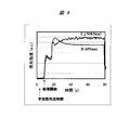
- FIG. 9 is a drawing previously examined by the inventor of the present application in order to quickly determine inactivation of the organism to be treated.
- the sterilization apparatuses in this field there is an apparatus that detects the emission intensity of carbon (C 2 ).
- C 2 emission intensity of carbon
- yeast bacteria form a shell-like tissue outside the cytoplasm and are highly resistant to sterilization by heat and ultraviolet rays.
- Bacillus subtilis is irradiated with plasma, the outer shell is first altered, and then the inner cells are altered.
- the object of the present invention is to determine the presence of bacteria and the activity / inactivity in real time by measuring a specific emission spectrum of a component derived from a living organism when performing sterilization using plasma. It is an object of the present invention to provide a plasma sterilization apparatus which can be sterilized.
- a plasma sterilization apparatus includes a power source that outputs an alternating voltage, a plasma source that is driven by the power source, and hydrogen from a region where gas radicalized by the plasma source exists.
- a light emission intensity detection unit that detects the light emission intensity of the hydroxyl group, and a control unit that controls the output of the power source based on the light emission intensity.
- a plasma sterilization system includes a power source that outputs an alternating voltage, a plasma source that is driven by the power source, and a region in which a gas radicalized by the plasma source exists.
- a light emission intensity detecting unit for detecting the light emission intensity of hydrogen or hydroxyl group, a clock for determining a detection time of the light emission intensity, and controlling the output of the power source based on the light emission intensity within a certain period measured by the clock.
- a control unit for detecting the light emission intensity of hydrogen or hydroxyl group, a clock for determining a detection time of the light emission intensity, and controlling the output of the power source based on the light emission intensity within a certain period measured by the clock.
- a plasma sterilization method of the present invention includes a power source that outputs an alternating voltage, a plasma source that is driven by the power source, a light emission intensity detector that detects light emission intensity, A control unit that performs control to change the output, a first step of applying the output of the power source to the plasma source, a second step of generating a gas radicalized by the plasma source, There is a third step of detecting the emission intensity of hydrogen or hydroxyl group emitted from the existing region, and a fourth step of controlling the output of the power source based on the emission intensity.
- sterilization can be performed with high efficiency at the time of sterilization using plasma.
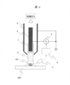
- FIG. 1 is a schematic diagram showing the configuration of the plasma sterilization apparatus of the present invention.
- a plasma source supplied with process gas under atmospheric pressure.
- a high-frequency electrode 3 and a ground electrode 3 ′ to which power is applied from a high-frequency power source 2 are installed on the outer periphery of the insulator 1 (for example, a glass tube), and the plasma 4 is generated in the tube of the insulator 1.
- the target organism 101 on the processing target surface 100 is irradiated with plasma.
- the plasma irradiation here is a gas generated when discharged, and refers to a state in which charged particles that move freely exist and are electrically neutral. That is, not only does the discharge part directly act on the bacteria, but also includes a phenomenon in which radicals generated by the discharge have a sterilizing action on the bacteria. Therefore, sterilization can be performed if a radical generation region exists on the processing target surface 100 instead of a discharge region.
- the processing target surface 100 is a floor or wall of the BCR, and the processing target organism 101 is, for example, Bacillus subtilis.
- Oxygen radicals are generated in the plasma 4 by using or adding oxygen as a gas for generating the plasma 4.
- oxygen radicals When the treatment target organism 101 is irradiated with the plasma 4, desorption of hydrogen starts from the surface of the cell wall of the treatment target organism 101 by oxygen radicals. As a result, the target organism 101 is inactivated by the alteration of the surface protein.
- the emission time (for example, 655 nm) of hydrogen in the plasma 4 is measured by the spectroscope 5 to detect the start time and the end time of hydrogen desorption.
- the desorption of hydrogen is completed, that is, when the amount of luminescence of hydrogen is attenuated and the amount of luminescence becomes constant, the treatment target organism 101 is inactivated. Activation can be determined.
- the detection information of the hydrogen emission intensity from the spectroscope 5 is sent to the control board 6 of the high-frequency power source 2.
- the output power of the high-frequency power source 2 may be set lower to save power.
- the output power of the high-frequency power source 2 is increased until the inactivation of the treatment target organism 101 is confirmed. This increases the amount of oxygen radicals generated in the plasma, and inactivates the target organism 101 at high speed.
- the processing target organism 101 when the processing target organism 101 is monitored by detecting the emission spectrum of hydrogen, for example, when water is attached to the processing target surface 100 in the BCR, water may be detected.
- the emission spectrum of a substance derived from a living body may be detected together with the emission spectrum of hydrogen.
- Phosphorus is a component contained in biological lipids and not in water or other organic matter. That is, the emission spectrum of phosphorus is detected to determine the presence of the treatment target organism 101, and the inactivation of the treatment target organism 101 may be determined from the emission spectrum of hydrogen.
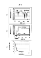
- FIG. 2 is an explanatory diagram of the method for detecting the organism to be treated according to the present invention.
- (A) is a measurement result of an emission spectrum when air is used as a processing gas and yeast (Saccharomyces cerevisiae) is used as a processing target organism.
- the horizontal axis represents wavelength, and the vertical axis represents emission intensity difference.
- the difference in emission intensity means that the waveform in the absence of yeast is subtracted from the waveform in the presence of yeast.
- the processing gas, air contains about 20% oxygen, and the hydrogen emission peak can be detected by desorption of hydrogen on the yeast surface by oxygen radicals in the plasma.
- oxygen radicals show a negative value because oxygen radicals are consumed when hydrogen or the like is desorbed.
- the installation area of yeast is about 2% of the area irradiated with plasma, but the emission intensity of hydrogen can be sufficiently detected.
- (B) shows how the luminescence intensity of hydrogen from which the luminescence peak was detected in (a) changes with time.
- the desorption of hydrogen starts with oxygen plasma, and the desorption of hydrogen is attenuated after about 30 seconds, and the intensity of the hydrogen emission spectrum (for example, 655 nm) becomes constant.
- the intensity of the hydrogen emission spectrum (for example, 655 nm) becomes constant.
- the AC power supply is stopped. Since the emission intensity changes with time in this way, it is preferable to perform control by setting a certain value, which is determined to have changed, as a threshold value.
- (C) shows the relationship between the plasma irradiation time and the number of viable bacteria.
- the yeast after each treatment time was cultured on the medium, and the number of viable bacteria was measured by the colony counting method. As a result, inactivation of yeast can be confirmed at the same time as hydrogen is desorbed by oxygen radicals in the plasma.
- FIGS. 1 and 2 Although a series of explanations are given in FIGS. 1 and 2, each configuration will be further explained.
- the insulator 1 is related to the nature of the plasma to be generated. When plasma is generated by performing air discharge from the electrodes, high-current arc discharge is performed. However, by using the insulator 1, a glow discharge with a small current can be performed, and power saving can be achieved. Therefore, the insulator 1 is provided in order to save the power consumption of the discharge, and the insulator 1 is not necessarily required for carrying out the present invention. Further, glow discharge can reduce the volume of the discharge space as compared with other discharge methods, and is suitable for a miniaturized apparatus as in the present invention.
- the high frequency power source 2 controls the potential and frequency necessary for discharging.
- the inactivation speed of the target organism 101 can be increased by increasing the amplitude or frequency of the potential.
- the amplitude and frequency of the potential may be decreased.
- it may be controlled by a potential / frequency that can generate a glow discharge with a small current without the insulator 1.
- the high-frequency voltage is controlled in a discontinuous pulse shape to suppress the amount of current flowing in the plasma.
- the high-frequency power source 2 can sometimes save the power of the apparatus, so that the insulator 1 for power saving can be omitted.
- the high-frequency electrode 3 and the ground electrode 3 ' can change the properties of the plasma generated by changing their shapes. By changing the electrode shape, it is possible to reduce the power consumption of the device as in the case of the insulator 1 and the high-frequency power source 2 described above.
- plasma is generated according to the electric field formed by the high-frequency electrode 3 and the ground electrode 3 '. Therefore, if the high-frequency electrode 3 and the ground electrode 3 ′ are arranged so as to be close to the processing target surface 100, higher-density plasma can be applied to the processing target surface 100. However, since the plasma may be at a high temperature, the plasma processing target surface 100 may have a distance that does not cause temperature degradation.
- sterilization of the wall surface can be handled by placing the part to be sterilized on the wall surface.
- the device may be moved along the wall surface while moving the portion to be sterilized over the wall surface.
- the treatment target organism 101 is exemplified as Bacillus subtilis, for example.
- Bacillus subtilis is exemplified is that it exhibits high resistance to sterilization by heat and ultraviolet rays and is employed in biological indicator (BI) in this field. Therefore, the present invention is also effective against bacteria having high resistance to sterilization by heat or ultraviolet rays, and a wide range of bacteria that can be treated other than Bacillus subtilis and yeast.
- the gas for generating plasma 4 is oxygen.
- the gas is not particularly limited as long as it is a gas for desorbing organic substances.
- the reason for selecting oxygen here is that it is present in the atmosphere and has a high effect of desorbing organic substances.
- a fan for blowing air may be attached.
- more radicalized gas is present on the processing surface 100, and the processing efficiency can be increased.
- the forced convection device can be omitted, although the processing efficiency is lower than when there is a forced convection device.
- the detection target of the change in wavelength intensity can determine inactivation even by measuring the emission spectrum of a hydroxyl group (OH) in addition to hydrogen. As shown in the detection result of hydroxyl group (OH) in FIG. 2 (b), although the emission spectrum of hydroxyl group (OH) is lower in intensity than the emission spectrum of hydrogen, it is sufficient to determine the presence of active or inactive bacteria. Detection sensitivity.
- the emission spectrum of each substance means a wavelength range in which the emission intensity of each substance such as hydrogen, hydroxyl group and phosphorus can be obtained satisfactorily.
- a generally known wavelength region for each substance is 410 nm to 490 nm in the case of hydrogen, or 650 nm to 660 nm with a peak at 656 nm.
- 302.1 nm to 308.9 nm is typical, and in the case of phosphorus, 215.4 nm to 255.5 nm or 919.4 nm to 1058.2 nm is typical. In this way, detection may be performed by selecting from a wavelength range in which the emission intensity of each substance can be satisfactorily obtained.
- the spectroscope 5 uses a color filter or a light receiving element to detect the emission intensity at a wavelength at which the emission intensity of each substance can be obtained satisfactorily, and does not necessarily detect the entire visible light region. Since it is only necessary to detect the intensity of a specific wavelength, the apparatus can be downsized and the cost can be reduced. In addition to directing the light incident part of the spectroscope 5 directly to the processing target surface 100, even better detection sensitivity can be obtained by using a condensing lens or an optical fiber.
- the processing target surface 100 and the light incident part of the spectroscope 5 are interposed by an optical fiber, it is not necessary to install the spectroscope 5 in the vicinity of the processing target surface 100, and the degree of freedom of equipment arrangement can be increased.
- a suction part for sucking inactivated bacteria and dust may be further attached.
- the cleanliness of the room can be increased by sucking the inactivated bacteria and the dust around them, and there is a synergistic effect that prevents the bacteria from growing.
- the second embodiment of the present invention is shown below. Even with a plasma generation method other than the first embodiment, it is possible to determine the presence and inactivity of the target organism 101 by the emission spectrum of the present invention.
- FIG. 3 is a schematic diagram showing another example of the configuration of the plasma sterilization apparatus of the present invention.
- the high-frequency electrode 3 and the ground electrode 3 ′ are opposed to each other, and at least one of the electrodes is protected by the insulator 1.
- Plasma 4 is generated at a position where the space between the opposed electrodes is the narrowest, and is irradiated to the processing target organism 101 on the processing target surface 100 along the flow of the processing gas.
- the spectroscope 5 and the control board 6 are installed, and the output of the high-frequency power source 2 is controlled based on the intensity information of the emission spectrum of hydrogen. If the high-frequency voltage supplied from the high-frequency power source 2 can be controlled in a discontinuous pulse shape and the amount of current flowing in the plasma can be suppressed, the inside of the BCR can be used even if there is no insulator protecting the electrode. The plasma does not become so hot that it degrades the surface 100 to be processed.
- the plasma discharge unit and the processing target organism 101 can be brought closer to each other than the configuration of FIG. Therefore, radical deactivation in the plasma can be further reduced, and power-saving sterilization can be performed.
- FIG. 4 is a schematic diagram showing still another example of the configuration of the plasma sterilization apparatus of the present invention.
- the insulator 1 since the plasma is generated while sticking to the surface of the insulator 1, the insulator 1 is directly brought close to the processing target surface 100. Thereby, plasma can be generated in a large area, and a wide range of the processing target surface 100 can be collectively processed.
- the method for measuring the emission spectrum is the same as in FIG.
- the third embodiment of the present invention is shown below.
- FIG. 5 is a schematic diagram showing the configuration of the plasma sterilization apparatus and the surface to be processed according to the present invention.
- An electric field is formed between the high-frequency electrode 4 and the ground electrode 7 for the processing target surface by installing the ground electrode 7 for the processing target surface on the outermost surface of the processing target surface 100.
- the plasma is accelerated by the electric field and collides with the target organism 101, and hydrogen desorption of the target organism 101 due to oxygen radicals is accelerated.
- Fig. 6 shows a self-propelled plasma sterilizer.
- the plasma sterilization apparatus of any one of FIGS. 1 or 3 to 5 of the present invention is mounted on a robot having a moving part, and BCR Just move around.
- FIG. 6 (a) shows an example in which the plasma sterilizer of FIG. 4 is mounted on a self-propelled robot. As shown in (b), the autonomous traveling is to move without hesitation while avoiding the obstacle 8 inside the object. At this time, when the processing target organism 101 is searched for while generating plasma with low power, and the processing target organism 101 is detected, an operation for stopping the movement and increasing the output of plasma generation may be programmed. .
- the device 102 may move back through the BCR by autonomous traveling and then return to the charging space installed in the BCR.
- the device 102 may be operated once every few hours or once a day depending on the degree of cleanness required for the BCR.
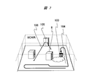
- FIG. 7 is a schematic view in which the plasma sterilization apparatus is provided with a logger function for storing light intensity detection information inside the apparatus or outside the apparatus main body and incorporated in the entire BCR system.
- a logger function for storing light intensity detection information inside the apparatus or outside the apparatus main body and incorporated in the entire BCR system.
- mapping by combining the above-mentioned logger function with the rotation information of the moving part motor, it is possible to map where the contamination is on the field.
- a sensor for obtaining positional information as appropriate may be provided.
- mapping information obtained in this way with the result of the work table or personnel layout in the BCR, it is possible to identify the easily contaminated place 104 or the easily contaminated time depending on the layout. .
- the BCR By performing a sterilization operation in which the specified place and time are weighted, the BCR can be further operated with a low contamination level.
- the air convection device (for example, air conditioner) 105 in the BCR is controlled so as not to cause air convection at the specified location and time.
- an alert function may be provided in which a display monitor or the like is incorporated in the system, the specified location and time are displayed, and movement of measuring devices or people in the BCR is suppressed.
- the fifth embodiment of the present invention is shown below.
- FIG. 8 is a schematic view showing a plasma sterilization apparatus for airborne bacteria according to the present invention.
- inactivation of the processing target organism 101 floating in the air is important in addition to the processing target organism attached to the floor or wall.
- a plasma sterilization apparatus similar to that shown in FIG. 4 is installed in the processing box 103, the emission spectrum of plasma in the processing box 103 is detected by the spectroscope 5, and the output of the high frequency power source 2 is output by the control board 6 based on the signal. May be feedback-controlled.
- the light emission information of the organism 101 to be processed floating in the BCR is output from the spectroscope 5 and the air flow rate of the air convection device in the BCR can be controlled.
- the target target organisms 101 in the BCR can be killed at a higher speed by increasing the blast volume of the high-frequency power supply 2 or the air convection device.
- the present invention at the time of sterilization using plasma, it is possible to detect the location of bacteria and irradiate the plasma only on the necessary location. Also, the irradiation time can be determined by judging inactivation, and the entire BCR chamber can be sterilized with high efficiency. As a result, it is only necessary to perform sterilization work on active bacteria in the BCR, and it is not necessary to completely stop the operation of the BCR for several days for sterilization. In addition, the output power of the power source can be increased for plasma generation at the location where the active bacteria are present, and sterilization in the BCR can be performed with low power consumption.
- the sterilization technology for surface-adherent bacteria using plasma proposed in this study is mainly intended for indoor sterilization of BCR for regenerative medicine, but it requires the removal of microorganisms such as medical and food manufacturing facilities and hospital facilities. Can be diverted to various facilities. Moreover, it can be used not only for sterilization of airborne bacteria, but also for household appliances such as sterilization in houses and refrigerators.
Landscapes
- Physics & Mathematics (AREA)
- Health & Medical Sciences (AREA)
- Engineering & Computer Science (AREA)
- Plasma & Fusion (AREA)
- Life Sciences & Earth Sciences (AREA)
- General Health & Medical Sciences (AREA)
- Spectroscopy & Molecular Physics (AREA)
- Epidemiology (AREA)
- Animal Behavior & Ethology (AREA)
- Public Health (AREA)
- Veterinary Medicine (AREA)
- Chemical & Material Sciences (AREA)
- Nuclear Medicine, Radiotherapy & Molecular Imaging (AREA)
- Fluid Mechanics (AREA)
- Analytical Chemistry (AREA)
- Biochemistry (AREA)
- General Physics & Mathematics (AREA)
- Immunology (AREA)
- Pathology (AREA)
- Chemical Kinetics & Catalysis (AREA)
- General Chemical & Material Sciences (AREA)
- Apparatus For Disinfection Or Sterilisation (AREA)
- Disinfection, Sterilisation Or Deodorisation Of Air (AREA)
- Plasma Technology (AREA)
Abstract
Description
1)乾熱滅菌法、高圧蒸気滅菌法、煮沸滅菌法などの加熱による滅菌法
2)放射線(γ線など)、紫外線(波長254nm付近)、電子線などによる照射滅菌法
3)エチレンオキサイドガス、過酸化水素などによるガス滅菌法
2…高周波電源
3…高周波電極
3’…アース電極
4…プラズマ
5…分光器
6…制御基板
7…処理対象面用アース電極
8…障害物
9…表示手段
100…処理対象面
101…処理対象生物
102…自走式プラズマ滅菌装置
103…処理ボックス
104…汚染されやすい場所
105…空気対流装置
106…空気の対流の強度
Claims (15)
- 交流電圧を出力する電源と、
前記電源により駆動されるプラズマ源と、
前記プラズマ源によりラジカル化された気体が存在する領域からの水素又は水酸基の発光強度を検出する発光強度検出部と、
前記発光強度に基づいて前記電源の出力を制御する制御部と、
を有するプラズマ滅菌装置。 - 請求項1において、
前記制御部は前記発光強度が一定値より低い時は、前記発光強度が一定値より高い時よりも前記電源の出力を減少させる制御を行うこと、
を特徴とするプラズマ滅菌装置。 - 請求項1において、前記プラズマ源はさらに
前記交流電圧が印加されプラズマを生成する高周波電極及びアース電極と、
を有するプラズマ滅菌装置。 - 請求項3において、前記プラズマ源はさらに
前記高周波電極または前記アース電極のうち少なくとも一方に形成された絶縁膜と、
を有するプラズマ滅菌装置。 - 請求項1において、
前記電源は、前記制御部からの信号の入力によって電位または周波数の出力を変化させること、
を特徴とするプラズマ滅菌装置。 - 請求項1において、
前記プラズマ源は、グロー放電を行うこと
を特徴とするプラズマ滅菌装置。 - 請求項1において、
前記プラズマ源は、大気中で放電し酸素ラジカルを生成すること
を特徴とするプラズマ滅菌装置。 - 請求項7において、前記プラズマ源はさらに
前記プラズマ源へ酸素を送り込む対流部と、
を有するプラズマ滅菌装置。 - 請求項1において、前記発光強度検出部はさらに
可視光領域の分光スペクトルを検出できる分光光度計と、
を有するプラズマ滅菌装置。 - 請求項1において、
前記発光強度検出部は、リンの発光強度を検出すること
を特徴とするプラズマ滅菌装置。 - 請求項1において、前記プラズマ源はさらに
菌や埃を吸引する吸引部と、
を有するプラズマ滅菌装置。 - 交流電圧を出力する電源と、
前記電源で駆動されるプラズマ源と、
前記プラズマ源によりラジカル化された気体が存在する領域からの水素又は水酸基の発光強度を検出する発光強度検出部と、
前記発光強度の検出時間を定めるクロックと、
前記クロックが測定する一定期間内における前記発光強度に基づいて、前記電源の出力を制御する制御部と、
を有するプラズマ滅菌システム。 - 請求項12において、前記プラズマ滅菌システムはさらに
バイオクリーンルーム内の空気を対流させる空気対流装置と、
前記クロックが測定する一定期間内において前記発光強度が一定値より低い時は、前記発光強度が一定値より高い時よりも前記空気対流装置の送風量を減少させる制御を行う制御部と、
を有するプラズマ滅菌システム。 - 交流電圧を出力する電源と、前記電源により駆動されるプラズマ源と、発光強度を検出する発光強度検出部と、前記電源の出力を変化させる制御を行う制御部とを有し、
前記電源の出力を前記プラズマ源に印加する第1ステップと、
前記プラズマ源によりラジカル化された気体を発生させる第2ステップと、
前記気体の存在領域から発光される、水素又は水酸基の発光強度を検出する第3ステップと、
前記発光強度に基づいて前記電源の出力を制御する第4ステップと、
を有するプラズマ滅菌方法。 - 請求項14において、前記プラズマ滅菌方法はさらに
前記気体の存在領域から発光される、リンの発光強度を検出する第5ステップと、
を有するプラズマ滅菌方法。
Priority Applications (3)
| Application Number | Priority Date | Filing Date | Title |
|---|---|---|---|
| PCT/JP2010/068550 WO2012053083A1 (ja) | 2010-10-21 | 2010-10-21 | プラズマ滅菌装置、プラズマ滅菌システムおよびプラズマ滅菌方法 |
| JP2012539519A JP5557923B2 (ja) | 2010-10-21 | 2010-10-21 | プラズマ滅菌装置、プラズマ滅菌システムおよびプラズマ滅菌方法 |
| US13/823,122 US20130202479A1 (en) | 2010-10-21 | 2010-10-21 | Plasma sterilizer, plasma sterilization system, and plasma sterilization method |
Applications Claiming Priority (1)
| Application Number | Priority Date | Filing Date | Title |
|---|---|---|---|
| PCT/JP2010/068550 WO2012053083A1 (ja) | 2010-10-21 | 2010-10-21 | プラズマ滅菌装置、プラズマ滅菌システムおよびプラズマ滅菌方法 |
Publications (1)
| Publication Number | Publication Date |
|---|---|
| WO2012053083A1 true WO2012053083A1 (ja) | 2012-04-26 |
Family
ID=45974819
Family Applications (1)
| Application Number | Title | Priority Date | Filing Date |
|---|---|---|---|
| PCT/JP2010/068550 Ceased WO2012053083A1 (ja) | 2010-10-21 | 2010-10-21 | プラズマ滅菌装置、プラズマ滅菌システムおよびプラズマ滅菌方法 |
Country Status (3)
| Country | Link |
|---|---|
| US (1) | US20130202479A1 (ja) |
| JP (1) | JP5557923B2 (ja) |
| WO (1) | WO2012053083A1 (ja) |
Cited By (11)
| Publication number | Priority date | Publication date | Assignee | Title |
|---|---|---|---|---|
| CN103212096A (zh) * | 2012-10-29 | 2013-07-24 | 北京大学 | 一种用于导尿管消毒的介质阻挡放电等离子体装置 |
| JP2013245989A (ja) * | 2012-05-24 | 2013-12-09 | Ihi Corp | 物質特定装置および物質特定方法 |
| WO2014073423A1 (ja) * | 2012-11-06 | 2014-05-15 | シャープ株式会社 | 空気調和システム |
| WO2014073476A1 (ja) * | 2012-11-06 | 2014-05-15 | シャープ株式会社 | 空気調和システム |
| US20140225502A1 (en) * | 2013-02-08 | 2014-08-14 | Korea Institute Of Machinery & Materials | Remote plasma generation apparatus |
| WO2014111081A3 (de) * | 2013-01-15 | 2014-09-12 | Cinogy Gmbh | Plasma-behandlungsgerät mit einer drehbar in einem griffgehäuse gelagerten rolle |
| JP2015205165A (ja) * | 2014-04-09 | 2015-11-19 | パナソニックIpマネジメント株式会社 | イオン噴霧装置、イオン噴霧システム及びイオン噴霧方法 |
| WO2019180703A1 (en) * | 2018-03-18 | 2019-09-26 | Nova Plasma Ltd. | Method and apparatus for pre-treating a catheter |
| JP2020518996A (ja) * | 2017-04-28 | 2020-06-25 | ソンシク チャン | 自由電荷、オゾン、および光を生成するエネルギー効率の良いプラズマプロセス |
| CN116870211A (zh) * | 2023-07-12 | 2023-10-13 | 广州海珠海之康医疗科技有限公司 | 一种等离子灭菌消毒系统及智能消毒柜 |
| TWI890042B (zh) * | 2022-03-31 | 2025-07-11 | 日商住友重機械工業股份有限公司 | 負離子生成裝置 |
Families Citing this family (5)
| Publication number | Priority date | Publication date | Assignee | Title |
|---|---|---|---|---|
| US10349648B2 (en) * | 2015-09-07 | 2019-07-16 | Scrubbing Fumigants Pty Ltd | Fumigation system and method |
| WO2017064265A1 (en) * | 2015-10-16 | 2017-04-20 | Inficon Gmbh | Optical detection of tracer gases in a gas discharge cell having unexposed electrodes |
| US20190262489A1 (en) * | 2016-05-31 | 2019-08-29 | Plasmamedic Ltd. | Plasma sterilization and feedback system |
| EP4115713A4 (en) * | 2020-03-02 | 2024-03-27 | The Regents of the University of California | PLASMA SOURCES FOR GENERATING COLD PLASMA |
| WO2021215560A1 (ko) * | 2020-04-23 | 2021-10-28 | 주식회사 이디티 | 플라즈마 처리 시스템 |
Citations (7)
| Publication number | Priority date | Publication date | Assignee | Title |
|---|---|---|---|---|
| JP2006075285A (ja) * | 2004-09-08 | 2006-03-23 | Sharp Corp | 物体の物性または機能を変化させる方法および細胞の生体機能を消失させる方法 |
| JP2006176211A (ja) * | 2004-11-26 | 2006-07-06 | Dainippon Printing Co Ltd | 殺菌方法および殺菌装置 |
| JP2007117254A (ja) * | 2005-10-26 | 2007-05-17 | Sharp Corp | 空気浄化装置 |
| JP2008135286A (ja) * | 2006-11-28 | 2008-06-12 | Osaka Univ | プラズマ表面処理装置 |
| JP2008173521A (ja) * | 2006-08-09 | 2008-07-31 | Honda Electronic Co Ltd | 液中プラズマ処理装置、及び液中プラズマ処理方法 |
| JP2008286784A (ja) * | 2007-04-18 | 2008-11-27 | Panasonic Corp | 分圧測定方法および分圧測定装置 |
| JP2009545673A (ja) * | 2006-08-01 | 2009-12-24 | レール・リキード−ソシエテ・アノニム・プール・レテュード・エ・レクスプロワタシオン・デ・プロセデ・ジョルジュ・クロード | プラスチックボトルのコールドプラズマ処理及びそれを行うための装置 |
Family Cites Families (3)
| Publication number | Priority date | Publication date | Assignee | Title |
|---|---|---|---|---|
| AU2002365929A1 (en) * | 2001-11-02 | 2003-09-02 | Plasmasol Corporation | Sterilization and decontamination system using a plasma discharge and a filter |
| ATE467335T1 (de) * | 2005-03-09 | 2010-05-15 | Askair Technologies Ag | Verfahren zur führung einer durchfluss- plasmavorrichtung |
| US7615931B2 (en) * | 2005-05-02 | 2009-11-10 | International Technology Center | Pulsed dielectric barrier discharge |
-
2010
- 2010-10-21 US US13/823,122 patent/US20130202479A1/en not_active Abandoned
- 2010-10-21 WO PCT/JP2010/068550 patent/WO2012053083A1/ja not_active Ceased
- 2010-10-21 JP JP2012539519A patent/JP5557923B2/ja not_active Expired - Fee Related
Patent Citations (7)
| Publication number | Priority date | Publication date | Assignee | Title |
|---|---|---|---|---|
| JP2006075285A (ja) * | 2004-09-08 | 2006-03-23 | Sharp Corp | 物体の物性または機能を変化させる方法および細胞の生体機能を消失させる方法 |
| JP2006176211A (ja) * | 2004-11-26 | 2006-07-06 | Dainippon Printing Co Ltd | 殺菌方法および殺菌装置 |
| JP2007117254A (ja) * | 2005-10-26 | 2007-05-17 | Sharp Corp | 空気浄化装置 |
| JP2009545673A (ja) * | 2006-08-01 | 2009-12-24 | レール・リキード−ソシエテ・アノニム・プール・レテュード・エ・レクスプロワタシオン・デ・プロセデ・ジョルジュ・クロード | プラスチックボトルのコールドプラズマ処理及びそれを行うための装置 |
| JP2008173521A (ja) * | 2006-08-09 | 2008-07-31 | Honda Electronic Co Ltd | 液中プラズマ処理装置、及び液中プラズマ処理方法 |
| JP2008135286A (ja) * | 2006-11-28 | 2008-06-12 | Osaka Univ | プラズマ表面処理装置 |
| JP2008286784A (ja) * | 2007-04-18 | 2008-11-27 | Panasonic Corp | 分圧測定方法および分圧測定装置 |
Cited By (21)
| Publication number | Priority date | Publication date | Assignee | Title |
|---|---|---|---|---|
| JP2013245989A (ja) * | 2012-05-24 | 2013-12-09 | Ihi Corp | 物質特定装置および物質特定方法 |
| CN103212096A (zh) * | 2012-10-29 | 2013-07-24 | 北京大学 | 一种用于导尿管消毒的介质阻挡放电等离子体装置 |
| WO2014073423A1 (ja) * | 2012-11-06 | 2014-05-15 | シャープ株式会社 | 空気調和システム |
| WO2014073476A1 (ja) * | 2012-11-06 | 2014-05-15 | シャープ株式会社 | 空気調和システム |
| JP2014092334A (ja) * | 2012-11-06 | 2014-05-19 | Sharp Corp | 空気調和システム |
| CN104755853A (zh) * | 2012-11-06 | 2015-07-01 | 夏普株式会社 | 空气调节系统 |
| CN104755853B (zh) * | 2012-11-06 | 2017-10-10 | 夏普株式会社 | 空气调节系统 |
| CN104871650B (zh) * | 2013-01-15 | 2017-08-22 | 奇诺格有限责任公司 | 具有可转动支承在把手壳体中的滚筒的等离子体处理设备 |
| WO2014111081A3 (de) * | 2013-01-15 | 2014-09-12 | Cinogy Gmbh | Plasma-behandlungsgerät mit einer drehbar in einem griffgehäuse gelagerten rolle |
| CN104871650A (zh) * | 2013-01-15 | 2015-08-26 | 奇诺格有限责任公司 | 具有可转动支承在把手壳体中的滚筒的等离子体处理设备 |
| US9287094B2 (en) | 2013-01-15 | 2016-03-15 | CYNOGY GmbH | Plasma treatment device comprising a roller mounted rotatably in a handle housing |
| US20140225502A1 (en) * | 2013-02-08 | 2014-08-14 | Korea Institute Of Machinery & Materials | Remote plasma generation apparatus |
| JP2015205165A (ja) * | 2014-04-09 | 2015-11-19 | パナソニックIpマネジメント株式会社 | イオン噴霧装置、イオン噴霧システム及びイオン噴霧方法 |
| JP2020518996A (ja) * | 2017-04-28 | 2020-06-25 | ソンシク チャン | 自由電荷、オゾン、および光を生成するエネルギー効率の良いプラズマプロセス |
| JP2023051903A (ja) * | 2017-04-28 | 2023-04-11 | ソンシク チャン | 自由電荷、オゾン、および光を生成するエネルギー効率の良いプラズマプロセス |
| JP7496402B2 (ja) | 2017-04-28 | 2024-06-06 | ソンシク チャン | 自由電荷、オゾン、および光を生成するエネルギー効率の良いプラズマプロセス |
| WO2019180703A1 (en) * | 2018-03-18 | 2019-09-26 | Nova Plasma Ltd. | Method and apparatus for pre-treating a catheter |
| US12090512B2 (en) | 2018-03-18 | 2024-09-17 | Nova Plasma Ltd. | Method and apparatus for pre-treating a catheter |
| TWI890042B (zh) * | 2022-03-31 | 2025-07-11 | 日商住友重機械工業股份有限公司 | 負離子生成裝置 |
| CN116870211A (zh) * | 2023-07-12 | 2023-10-13 | 广州海珠海之康医疗科技有限公司 | 一种等离子灭菌消毒系统及智能消毒柜 |
| CN116870211B (zh) * | 2023-07-12 | 2024-05-24 | 广州海珠海之康医疗科技有限公司 | 一种等离子灭菌消毒系统及智能消毒柜 |
Also Published As
| Publication number | Publication date |
|---|---|
| JPWO2012053083A1 (ja) | 2014-02-24 |
| JP5557923B2 (ja) | 2014-07-23 |
| US20130202479A1 (en) | 2013-08-08 |
Similar Documents
| Publication | Publication Date | Title |
|---|---|---|
| JP5557923B2 (ja) | プラズマ滅菌装置、プラズマ滅菌システムおよびプラズマ滅菌方法 | |
| KR100738174B1 (ko) | 미생물의 제거 평가 방법 및 미생물 제거 평가 장치 | |
| US6576188B1 (en) | Surface and air sterilization using ultraviolet light and ultrasonic waves | |
| Wang et al. | Experimental study of the disinfection performance of a 222-nm Far-UVC upper-room system on airborne microorganisms in a full-scale chamber | |
| JP7754150B2 (ja) | 静菌方法 | |
| CN113041370A (zh) | 隧道输送式紫外线新冠病毒杀菌消毒设备 | |
| US20190262489A1 (en) | Plasma sterilization and feedback system | |
| GB2432532A (en) | Sterilization method and sterilization apparatus | |
| Lin et al. | Ar/O 2 argon-based round atmospheric-pressure plasma jet on sterilizing bacteria and endospores | |
| CN107648631A (zh) | 脉冲氙气灯紫外线杀菌仪 | |
| Mok et al. | Afterglow corona discharge air plasma (ACDAP) for inactivation of common food-borne pathogens | |
| US20090311741A1 (en) | Environmental evaluation installation and environmental evaluation method | |
| JP2014136113A (ja) | 紫外線殺菌方法 | |
| KR101273888B1 (ko) | 평면형태의 대기압 공기 플라즈마를 이용한 소형의 다용도 멸균소독기 | |
| Abuzairi et al. | Development of the Sterilization Box for Medical Equipment with an Ozone Gas Leak Sensor Feature | |
| WO2019061035A1 (zh) | 用于消毒的紫外线系统以及紫外线消毒方法 | |
| JP4142974B2 (ja) | 微生物の除去評価方法および微生物除去評価装置 | |
| Edelblute et al. | Antibacterial efficacy of a novel plasma reactor without an applied gas flow against methicillin resistant Staphylococcus aureus on diverse surfaces | |
| JP2017213263A (ja) | アレルゲンの不活化方法およびアレルゲン不活化装置 | |
| JP2004159508A (ja) | 微生物の除去評価方法および微生物除去評価装置 | |
| JP2008022765A (ja) | 環境評価装置及び環境評価方法 | |
| He et al. | Quantitative evaluation of temperature and relative humidity effects on 222 nm UVGI air disinfection in a novel wind tunnel system | |
| JP2004159636A (ja) | 微生物の除去評価方法および微生物除去評価装置 | |
| CN101490272A (zh) | 环境评价设备及环境评价方法 | |
| SE2250041A1 (en) | A portable system comprising an ultraviolet lighting arrangement |
Legal Events
| Date | Code | Title | Description |
|---|---|---|---|
| 121 | Ep: the epo has been informed by wipo that ep was designated in this application |
Ref document number: 10858639 Country of ref document: EP Kind code of ref document: A1 |
|
| ENP | Entry into the national phase |
Ref document number: 2012539519 Country of ref document: JP Kind code of ref document: A |
|
| WWE | Wipo information: entry into national phase |
Ref document number: 13823122 Country of ref document: US |
|
| NENP | Non-entry into the national phase |
Ref country code: DE |
|
| 122 | Ep: pct application non-entry in european phase |
Ref document number: 10858639 Country of ref document: EP Kind code of ref document: A1 |