WO2012050166A1 - 医用画像処理装置及びx線コンピュータ断層撮影装置 - Google Patents
医用画像処理装置及びx線コンピュータ断層撮影装置 Download PDFInfo
- Publication number
- WO2012050166A1 WO2012050166A1 PCT/JP2011/073556 JP2011073556W WO2012050166A1 WO 2012050166 A1 WO2012050166 A1 WO 2012050166A1 JP 2011073556 W JP2011073556 W JP 2011073556W WO 2012050166 A1 WO2012050166 A1 WO 2012050166A1
- Authority
- WO
- WIPO (PCT)
- Prior art keywords
- cross
- section
- volume data
- processing apparatus
- medical image
- Prior art date
- Legal status (The legal status is an assumption and is not a legal conclusion. Google has not performed a legal analysis and makes no representation as to the accuracy of the status listed.)
- Ceased
Links
Images







Classifications
-
- A—HUMAN NECESSITIES
- A61—MEDICAL OR VETERINARY SCIENCE; HYGIENE
- A61B—DIAGNOSIS; SURGERY; IDENTIFICATION
- A61B6/00—Apparatus or devices for radiation diagnosis; Apparatus or devices for radiation diagnosis combined with radiation therapy equipment
- A61B6/52—Devices using data or image processing specially adapted for radiation diagnosis
- A61B6/5258—Devices using data or image processing specially adapted for radiation diagnosis involving detection or reduction of artifacts or noise
- A61B6/5264—Devices using data or image processing specially adapted for radiation diagnosis involving detection or reduction of artifacts or noise due to motion
-
- A—HUMAN NECESSITIES
- A61—MEDICAL OR VETERINARY SCIENCE; HYGIENE
- A61B—DIAGNOSIS; SURGERY; IDENTIFICATION
- A61B6/00—Apparatus or devices for radiation diagnosis; Apparatus or devices for radiation diagnosis combined with radiation therapy equipment
- A61B6/02—Arrangements for diagnosis sequentially in different planes; Stereoscopic radiation diagnosis
- A61B6/03—Computed tomography [CT]
- A61B6/032—Transmission computed tomography [CT]
-
- A—HUMAN NECESSITIES
- A61—MEDICAL OR VETERINARY SCIENCE; HYGIENE
- A61B—DIAGNOSIS; SURGERY; IDENTIFICATION
- A61B6/00—Apparatus or devices for radiation diagnosis; Apparatus or devices for radiation diagnosis combined with radiation therapy equipment
- A61B6/40—Arrangements for generating radiation specially adapted for radiation diagnosis
- A61B6/4064—Arrangements for generating radiation specially adapted for radiation diagnosis specially adapted for producing a particular type of beam
- A61B6/4078—Fan-beams
-
- A—HUMAN NECESSITIES
- A61—MEDICAL OR VETERINARY SCIENCE; HYGIENE
- A61B—DIAGNOSIS; SURGERY; IDENTIFICATION
- A61B6/00—Apparatus or devices for radiation diagnosis; Apparatus or devices for radiation diagnosis combined with radiation therapy equipment
- A61B6/46—Arrangements for interfacing with the operator or the patient
- A61B6/467—Arrangements for interfacing with the operator or the patient characterised by special input means
- A61B6/469—Arrangements for interfacing with the operator or the patient characterised by special input means for selecting a region of interest [ROI]
-
- A—HUMAN NECESSITIES
- A61—MEDICAL OR VETERINARY SCIENCE; HYGIENE
- A61B—DIAGNOSIS; SURGERY; IDENTIFICATION
- A61B6/00—Apparatus or devices for radiation diagnosis; Apparatus or devices for radiation diagnosis combined with radiation therapy equipment
- A61B6/52—Devices using data or image processing specially adapted for radiation diagnosis
- A61B6/5258—Devices using data or image processing specially adapted for radiation diagnosis involving detection or reduction of artifacts or noise
- A61B6/5264—Devices using data or image processing specially adapted for radiation diagnosis involving detection or reduction of artifacts or noise due to motion
- A61B6/527—Devices using data or image processing specially adapted for radiation diagnosis involving detection or reduction of artifacts or noise due to motion using data from a motion artifact sensor
-
- G—PHYSICS
- G06—COMPUTING OR CALCULATING; COUNTING
- G06T—IMAGE DATA PROCESSING OR GENERATION, IN GENERAL
- G06T19/00—Manipulating three-dimensional [3D] models or images for computer graphics
-
- G—PHYSICS
- G06—COMPUTING OR CALCULATING; COUNTING
- G06T—IMAGE DATA PROCESSING OR GENERATION, IN GENERAL
- G06T2219/00—Indexing scheme for manipulating 3D models or images for computer graphics
- G06T2219/008—Cut plane or projection plane definition
Definitions
- Embodiments described herein relate generally to a medical image processing apparatus and an X-ray computed tomography apparatus.
- Recent ultrasonic diagnostic apparatuses can repeatedly collect data serving as a basis for three-dimensional images with high temporal resolution.
- CT X-ray computed tomography apparatuses
- MRI magnetic resonance imaging apparatuses
- an X-ray computed tomography apparatus will be described.
- a series of temporal volume data files are reconstructed by a cone beam reconstruction method or the like.
- a series of cross-sectional images are generated by MPR (cross-section conversion) processing or the like.
- a series of cross-sectional images is reproduced as a moving image.
- the purpose is to avoid a situation in which the region of interest deviates from the cross-sectional image due to the influence of respiratory motion or pulsation.
- the medical image processing apparatus generates a series of cross-sectional images from a series of volume data files related to a three-dimensional region of a subject, and generates a plurality of cross sections corresponding to the cross-sectional images as a plurality of volume data. Based on the position of the same part included in the file, the cross section determination unit individually determines the position.
- FIG. 1 is a diagram showing a configuration of an X-ray computed tomography apparatus including a medical image processing apparatus according to this embodiment.
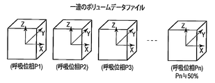
- FIG. 2 is a diagram showing a series of volume data files generated by the cone beam reconstruction processing unit of FIG.
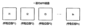
- FIG. 3 is a diagram showing a series of MPR images generated by the cross-sectional image generator of FIG.
- FIG. 4 is an explanatory diagram of alternate reproduction by the reproduction controller of FIG.
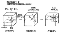
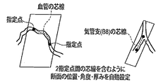
- FIG. 5 is an explanatory diagram of a cross-section manual setting mode by the cross-section position determining unit of FIG.
- FIG. 6 is an explanatory diagram of cross-sectional position interpolation processing by the cross-section position determining unit of FIG.
- FIG. 1 is a diagram showing a configuration of an X-ray computed tomography apparatus including a medical image processing apparatus according to this embodiment.
- FIG. 2 is a diagram showing a series of volume data files generated by the cone beam reconstruction processing unit of FIG.
- FIG. 3 is a diagram showing
- FIG. 7 is an explanatory diagram of a first automatic cross-section setting mode by the cross-section position determining unit of FIG.
- FIG. 8 is an explanatory diagram of a second automatic cross-section setting mode by the cross-section position determining unit of FIG.
- FIG. 9 is a supplementary explanatory diagram of the second automatic section setting mode of FIG.
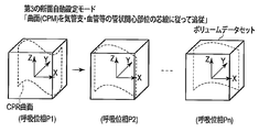
- FIG. 10 is an explanatory diagram of a third automatic section setting mode by the cross-section position determination unit of FIG.
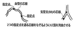
- FIG. 11 is a supplementary explanatory diagram of the third automatic section setting mode of FIG.
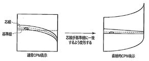
- FIG. 12 is a diagram showing a first image processing for a cross-sectional image generated under the third automatic cross-section setting mode of FIG. FIG.
- FIG. 13 is a diagram illustrating second image processing for a cross-sectional image generated under the third automatic cross-section setting mode of FIG.
- FIG. 14 is a diagram showing the effect of this embodiment.
- FIG. 15 is a diagram showing the effect of the present embodiment in comparison with the prior art.
- FIG. 16 is a diagram showing an example of a cross section set in the first automatic cross section setting mode of FIG.
- FIG. 17 is a diagram showing an example of a cross section set in the first automatic cross section setting mode of FIG. 18 is a diagram showing an example of a cross section set in the first automatic cross section setting mode of FIG.
- FIG. 19 is a diagram showing an example of a cross section set in the first automatic cross section setting mode of FIG.
- FIG. 20 is a diagram showing a cross-sectional example set by the second automatic cross-section setting mode of FIG.
- FIG. 21 is a view showing an example of a cross section set in the second automatic cross section setting mode of FIG.
- the medical image processing apparatus generates a series of cross-sectional images from a series of volume data files related to a three-dimensional region of a subject in an image generation unit, and includes a plurality of cross-sections respectively corresponding to the cross-sectional images included in the plurality of volume data files. Based on the position of the part, the cross section determination unit individually determines.
- the medical image processing apparatus is an object to be repeatedly generated by a medical image generation apparatus such as an X-ray computed tomography apparatus, a magnetic resonance imaging apparatus (MRI), an ultrasonic diagnostic apparatus, or an X-ray diagnostic apparatus.
- a series of volume data files related to the three-dimensional region of the specimen is set as a processing target.
- the medical image processing apparatus according to this embodiment is incorporated in these medical image generation apparatuses or is provided alone.
- the medical image processing apparatus according to the present embodiment is connected to an electrical communication line such as a LAN, and a series of images from a medical image interpolation communication system (PACS) inside or outside the hospital via the electrical communication line.
- PPS medical image interpolation communication system
- FIG. 1 is a block diagram showing the configuration of an X-ray computed tomography apparatus equipped with a medical image processing apparatus according to this embodiment.
- the gantry unit 100 includes a rotating frame 102 that is rotatably supported.
- a rotation center axis of the rotation frame 102 is defined as a Z axis.
- the Y axis is defined to pass through the X-ray focal point and the center of the detector 103 described later and to be orthogonal to the Z axis.
- the X axis is defined to be orthogonal to the Y axis and the Z axis.
- the gantry driving unit 107 generates a driving signal for rotating the rotating frame 102 under the control of the host controller 110.
- a cone beam X-ray tube 101 and a two-dimensional detector (also referred to as an area detector) 103 are mounted on the rotating frame 102 so as to face each other with a cylindrical imaging region S centered on the Z axis.
- an object placed on the top of the bed is arranged in the imaging region S.
- the subject is placed so that its body axis substantially coincides with the Z axis.
- a high voltage generator 109 supplies a tube current to the X-ray tube 101 and applies a high voltage under the control of the host controller 110. Thereby, X-rays are generated from the focal point F of the X-ray tube 101.
- the X-ray stop 111 shapes X-rays generated by the X-ray tube 101 into a quadrangular pyramid shape.
- the subject is irradiated with X-rays shaped into a quadrangular pyramid.
- the two-dimensional detector 103 has a plurality of X-ray detection element arrays.
- the plurality of X-ray detection element arrays are arranged in parallel in the Z-axis direction.
- Each X-ray detection element array is arranged in an arc shape around the X-ray focal point F.
- a data collection device 104 Connected to the two-dimensional detector 103 is a data collection device 104 generally called DAS (data acquisition system).
- the data acquisition device 104 includes an IV converter that converts a current signal of each channel of the two-dimensional detector 103 into a voltage, and an integration that periodically integrates the voltage signal in synchronization with an X-ray exposure cycle. And an analog / digital converter for converting the output signal of the preamplifier into a digital signal are provided for each channel.
- a pre-processing device 106 is connected to the output of the data collection device 104 via a non-contact data transmission device 105 that mediates an optical or magnetic element.
- the pre-processing device 106 corrects the non-uniform sensitivity between channels for the data detected by the data collection device 104, and the signal intensity is significantly reduced or dropped due to the X-ray strong absorber, mainly the metal part. Pre-processing such as correcting is performed.
- Data (projection data) that has undergone preprocessing by the preprocessing device 106 is stored in the projection data storage unit 112.
- so-called four-dimensional dynamic scan is executed under the control of the host controller 110.
- the rotating frame 102 is continuously rotated around the subject together with the X-ray tube 101 and the two-dimensional detector 103 during a predetermined imaging period.
- X-rays are continuously or pulsed from the X-ray tube 101, and the two-dimensional detector 103 repeats X-ray detection.
- the period in which the X-ray tube 101 rotates 360 ° or (180 ° + fan angle) is referred to as a scan period (first period).
- a single volume data file is reconstructed from projection data for the angular range of 360 ° or (180 ° + fan angle).
- the fan angle is an X-ray spread angle in the XY plane with the X-ray focal point as the center.
- the cone beam reconstruction processing unit 116 expresses the CT value distribution in a three-dimensional coordinate system by, for example, the cone beam reconstruction method based on the projection data stored in the projection data storage unit 112 under the control of the host controller 110. Reconfigure multiple volume data files. As described above, each volume data file is reconstructed from projection data for an angular range of 360 ° or (180 degrees + fan angle). In the plurality of volume data files, the angular range of projection data used for each reconstruction is shifted by, for example, 30 °. Thereby, the photographing time of each of the plurality of volume data files is shifted by the time required for rotation of 30 °.
- the photographing time is typically defined as the time when the projection data corresponding to the substantially central angle in the angular range of the projection data used for reconstruction is collected. If the scan period is a time width (first period) required for rotation of the angular range of the projection data used for reconstruction, the volume data file is generated in a second period shorter than the first period. A series of volume data files is stored in the volume data file storage unit 113.
- the cross-sectional image generation unit 115 includes a plurality of sections constituting a series by so-called MPR processing (cross-section conversion processing) or CPR processing (curved cross-section conversion processing) that is suitable for display on the display unit (display) 117.
- a plurality of cross-sectional images constituting a corresponding series are generated from each volume data file.
- the photographing time of the cross-sectional image coincides with the photographing time of the volume data file that is the origin thereof.
- the generated plurality of cross-sectional image data is stored in the volume data file storage unit 113.
- Each cross-sectional position and cross-sectional thickness are individually determined by the cross-sectional position determining unit 125 for a plurality of volume data files. Details regarding the determination of the cross-sectional position and the cross-sectional thickness will be described later.
- the playback controller 118 controls the reading of a series of cross-sectional image data from the volume data file storage unit 113 to display the series of cross-sectional images stored in the volume data file storage unit 113 on the display unit 117 as a moving image.
- This playback display is related to the periodic physiological movement of the subject.
- the periodic physiological movement is typically a respiratory movement or a heartbeat movement.
- the present invention can be applied to both respiratory exercise and heartbeat exercise.
- it demonstrates as a respiratory exercise.
- the respiratory motion of the subject is measured by the respiratory sensor 120, for example.
- the breathing movement is the expansion and contraction of the lung field accompanying the reciprocation of the diaphragm.
- the respiration sensor 120 repeatedly measures the distance between the abdominal surface of the subject and the external fixed point (laser irradiation position) as a respiration index using, for example, laser length measurement technology.
- This temporal change in distance reflects a change in the breathing state (breathing phase) of the subject.
- the maximum value / minimum value specifying unit 123 specifies the maximum value and the minimum value from the temporal change of the respiratory index during the imaging period. For example, the time when the breathing index shows the minimum value represents the expiration bottom time, and the time when the breathing index shows the maximum value represents the inspiration peak time. The period from the expiration bottom time to the inspiration peak time represents a substantially half cycle of the respiratory cycle.
- the playback controller 118 extracts, as playback target images, a plurality of cross-sectional images that include the imaging time in the period from the exhalation bottom time to the inspiration peak time from the series of cross-sectional images stored in the volume data file storage unit 113.
- the reproduction controller 118 repeatedly reproduces a series of cross-sectional images specified as reproduction target images.
- the playback controller 118 plays back a series of cross-sectional images in real time in the forward direction according to the order of the corresponding shooting times (forward playback). Real-time playback is performed in the reverse direction of the time (reverse playback), and forward playback and reverse playback are alternately repeated in this way. That is, the playback direction is alternately switched.
- a moving image that is alternately reproduced while limiting to approximately half a cycle of respiration is approximate to repetitive reproduction of a moving image of one breathing period.
- the respiratory phase is almost the same between the boundary frames of the alternate reproduction, and therefore, the displacement of the tissue distribution on the screen naturally does not occur between the boundary frames of the alternate reproduction. .
- variation by the respiration can be visually recognized with continuity. For example, when observing a moving image while paying attention to a tumor, it is preferable that the observer does not need to move the line of sight greatly.
- the shooting period is set to a semi-breathing period or a period slightly exceeding it, the reproduction can reproduce almost the same motion as a moving image obtained over one breathing period or a period exceeding it. Shortening the imaging period is most effective in reducing exposure.
- the above-described cross-section position determination unit 125 is equipped with a plurality of modes for cross-section determination. Any one of the plurality of cross-section determination modes can be arbitrarily selected according to a selection instruction by an operator via an input device (not shown).
- FIG. 5 is an explanatory diagram of the manual section determination mode.
- the XY plane orthogonal to the reference axis is set as the section with the Z axis as the reference axis.
- the cross section image generator 115 sets a common cross section candidate parallel to the XY plane for a number of volume data files discretely from a series of volume data files.
- the initial cross section candidate is set to an XY plane that passes through the origin of the XYZ coordinate system, for example.
- volume data files to be targeted for example, three volume data files at both ends and a center of a series of volume data files are initially selected.
- a cross-sectional image relating to the initial cross-section is generated by the cross-sectional image generator 115 for these three volume data files.
- Three cross-sectional images related to the initial cross-section are displayed on the display unit 117 simultaneously or alternatively.
- the operator searches for the position of the cross section where the image of the region of interest appears best while moving the cross section along the Z-axis via an input device (not shown), and, for example, approximately the center point (interest point) of the region of interest on the cross-sectional image. Point or designated point).
- Cross sections are individually searched for all three volume data files, and points of interest are designated.
- the cross-sectional position determination unit 125 calculates the interest point in the volume data file other than the three volume data files to be manually designated, on the time axis, as shown in FIG.
- the estimated interest point is on a straight line in the three-dimensional coordinate system connecting the two designated interest points sandwiching it, and the time of the manually designated volume data file with respect to the time of the volume data file to be interpolated
- a point calculated by linear interpolation is determined by the time widths ⁇ t1 and ⁇ t2 between them.
- a cross section that includes a point of interest designated or interpolated for each of a plurality of volume data files and that is parallel to the XY plane is determined for each of the volume data files. Note that the points of interest may be designated individually for all volume data files.
- the cross-sectional image generator 115 generates a plurality of cross-sectional images respectively corresponding to a plurality of volume data files according to the set cross-section.
- a plurality of cross-sectional images are stored in the volume data file storage unit 113.
- forward reproduction and reverse reproduction are alternately repeated as a moving image by the reading control by the reproduction controller 118 from the volume data file storage unit 113 to the display unit 117.
- the cross section is such that the point of interest on each cross-sectional image is arranged at a specific position on the display of the display unit 117, typically the central position. The display position of the image is shifted individually.
- a cross-sectional image including a region of interest is always displayed during moving image reproduction, and the image of the region of interest is fixed at a specific position on the screen.
- the region of interest can be suitably viewed on all cross-sectional images, and the movement of the line of sight is reduced, which is effective for diagnosis such as tumor adhesion.
- FIG. 7 is an explanatory diagram of the first automatic section setting mode.
- the XY plane orthogonal to the reference axis is set as the cross section with the Z axis as the reference axis.
- the section image generation unit 115 Under the activation of the first section automatic setting mode, the section image generation unit 115 generates a section image relating to an initial candidate passing through the origin parallel to the XY plane, for example, from a series of volume data files as a specific single volume data file. To do.
- the specific single volume data file is typically a volume data file closest to the central time in a series of volume data files.
- the operator searches for a cross section in which the image of the region of interest is most suitably reflected while moving the candidate cross section along the Z-axis via an input device (not shown), and designates a point in the region of interest on the cross-sectional image.
- the cross-sectional position determination unit 125 uses the threshold value to determine the three-dimensional interest from each of the other volume data files, using the pixel value of the specified point or the average value or median value of a plurality of pixels within the local range centered on the specified point as a threshold value. Extract regions. The cross-section position determination unit 125 sets a point of interest inside each extracted region of interest. There are various barriers to interest. An example of the point of interest is a centroid point or a point away from the centroid point by a predetermined distance ⁇ d in the Z-axis direction, as shown in FIG.
- point of interest is a point that divides a line segment passing through the center of gravity and parallel to the Z-axis and having both ends on the edge of the region of interest at a predetermined distance ratio, as shown in FIG.
- interest point is set at the center point of the pixel having the maximum CT value or the minimum CT value in the region of interest as shown in FIG.
- the center of gravity is initially set, the operator can select any one of these points of interest.
- the interest point setting method described with reference to FIGS. 16 to 18 can also be applied to the designated point designation method for blood vessels and bronchi in FIGS.
- ⁇ Section determination and moving image playback processing after the interest point is set are the same as the processing described in the manual setting mode described above.
- a cross section (cross section orthogonal to the Z axis (reference axis)) including the interest point set for each volume data file and parallel to the XY plane is determined.
- a cross-sectional image is generated from the volume data file by the MPR process according to the determined cross-section.
- cross-sectional images are generated for all volume data files. For a plurality of cross-sectional images, forward reproduction and reverse reproduction are alternately repeated under the reading control by the reproduction controller 118.
- an XY plane that bisects the volume of the extracted region of interest is searched, and a cross-sectional image is generated from the volume data file according to the XY plane (cross section). It may be.
- This first automatic section setting mode is suitable when the region of interest has a lump shape such as a tumor, as in the manual setting mode.
- FIG. 8 is an explanatory diagram of the second automatic section setting mode.
- the second automatic section determination mode an oblique surface that obliquely intersects the reference axis is set as a section with the Z axis as the reference axis.
- the second automatic section setting mode is suitable when the target is a tubular part such as a bronchus or a blood vessel.
- a blood vessel region is extracted from each of the series of volume data files by the cross-sectional position determination unit 125 by threshold processing.
- the section of interest including stenosis or the like is set for the extracted blood vessel region by the operator specifying two points at both ends thereof.
- the cross-sectional position determination unit 125 specifies the blood vessel core line of the extracted blood vessel region that passes through the two designated points.
- the cross-sectional position, the oblique angle with respect to each axis of XYZ, and the cross-sectional thickness are individually determined for each of the plurality of volume data files by the cross-sectional position determining unit 125 so as to include the designated blood vessel core line between two points.
- ⁇ Section image generation processing and moving image reproduction processing after the section determination are substantially equivalent to the processing described in the manual setting mode described above.
- a cross-sectional image is generated by integrating a plurality of voxel values along a direction (ray) perpendicular to the cross-section or extracting a maximum value from a plurality of voxel values on the same ray.
- a plurality of cross-sectional images are generated according to the cross-section determined for each of the plurality of volume data files. For a plurality of cross-sectional images, forward reproduction and reverse reproduction are alternately repeated under the reading control by the reproduction controller 118.
- the entire section of interest such as a complex bent blood vessel such as the coronary artery of the heart can always be visually confirmed on the screen.
- the second automatic cross-section setting mode that defines the oblique cross-section can be applied to a tumor having a lump shape.
- the oblique cross section passes through the center of gravity of the extracted region of interest, and the distance (diameter) of the line segment whose ends are on the region of interest edge, for example, the maximum diameter and the minimum diameter, or It is set to a plane defined by two line segments indicating the maximum diameter and the second longest diameter.
- the oblique section is set to a section in which the extracted sectional area of the region of interest has the maximum value, as shown in FIG.
- FIG. 10 is an explanatory diagram of the third automatic section setting mode.
- the third automatic section setting mode is also suitable when the target is a tubular part such as a bronchus or a blood vessel.
- a blood vessel region is extracted from each of the series of volume data files by the cross-sectional position determination unit 125 by threshold processing.
- a section of interest including stenosis or the like is set for the extracted blood vessel region by the operator specifying two points at both ends thereof.
- one point on the peripheral side of the blood vessel may be designated by the operator, traced automatically to the upper part of the blood vessel, and a section of interest may be set between the peripheral blood vessel and the upper part of the blood vessel.
- the cross-section position determination unit 125 identifies the blood vessel core line of the extracted blood vessel region that passes through the two specified points.
- a cross section perpendicular to the XY plane is curved while maintaining a state perpendicular to the XY plane along the projected image of the blood vessel core line between the two specified points on the XY plane. Thereby, a cross section (curved cross section) is determined for each of the plurality of volume data files.
- the cross-sectional image generation processing and moving image reproduction processing after the cross-section determination is the same as the processing described in the manual setting mode described above.
- a plurality of cross-sectional images respectively corresponding to the plurality of volume data files are generated according to the curved cross-section determined for each of the plurality of volume data files, and forward playback and reverse playback are performed under the read control by the playback controller 118. Repeated alternately.
- the entire section of interest such as a blood vessel that is bent in a complicated manner in a more detailed state than that in the second automatic section setting mode can always be visually confirmed on the screen.
- the cross-sectional image generator 115 transforms the blood vessel image that travels in a complex manner on the cross-sectional images generated in the second and third cross-section automatic setting modes into a straight line as shown in FIG. You may make it do.
- coordinate transformation as shown in FIG. 13, a plurality of line segments orthogonal to the center of the blood vessel core line are arranged, and a plurality of pixel columns on the plurality of line segments are rearranged in the orthogonal coordinate system.
- DESCRIPTION OF SYMBOLS 100 Base part, 101 ... X-ray tube, 102 ... Rotating frame, 103 ... Two-dimensional detector, 104 ... Data acquisition device, 106 ... Pre-processing apparatus, 107 ... Base drive part, 109 ... High voltage generator, 110 ... Host controller, 112 ... Projection data storage unit, 113 ... Volume data file storage unit, 115 ... Cross-sectional image generation unit, 116 ... Cone beam reconstruction processing unit, 117 ... Display unit (display), 118 ... Reproduction controller, 120 ... Breathing Sensor 121, breathing waveform storage unit 123, maximum value / minimum value specifying unit 125, cross-section position determining unit
Landscapes
- Engineering & Computer Science (AREA)
- Health & Medical Sciences (AREA)
- Life Sciences & Earth Sciences (AREA)
- Medical Informatics (AREA)
- Physics & Mathematics (AREA)
- Molecular Biology (AREA)
- Public Health (AREA)
- Biophysics (AREA)
- Nuclear Medicine, Radiotherapy & Molecular Imaging (AREA)
- Optics & Photonics (AREA)
- Pathology (AREA)
- Radiology & Medical Imaging (AREA)
- Biomedical Technology (AREA)
- Heart & Thoracic Surgery (AREA)
- Veterinary Medicine (AREA)
- Surgery (AREA)
- Animal Behavior & Ethology (AREA)
- General Health & Medical Sciences (AREA)
- High Energy & Nuclear Physics (AREA)
- Computer Vision & Pattern Recognition (AREA)
- Theoretical Computer Science (AREA)
- Computer Graphics (AREA)
- Computer Hardware Design (AREA)
- General Engineering & Computer Science (AREA)
- Software Systems (AREA)
- General Physics & Mathematics (AREA)
- Human Computer Interaction (AREA)
- Pulmonology (AREA)
- Apparatus For Radiation Diagnosis (AREA)
- Magnetic Resonance Imaging Apparatus (AREA)
- Ultra Sonic Daignosis Equipment (AREA)
Abstract
目的は、呼吸動や拍動の影響により関心部位が画像から外れてしまう事態を軽減することにある。 医用画像処理装置は、被検体の3次元領域に関する一連のボリュームデータファイルから一連の断面画像を画像発生部(115)で発生し、断面画像にそれぞれ対応する複数の断面を複数のボリュームデータファイルに含まれる同一部位の位置に基づいて断面決定部(125)で個々に決定する。
Description
本発明の実施形態は、医用画像処理装置及びX線コンピュータ断層撮影装置に関する。
近年の超音波診断装置、X線コンピュータ断層撮影装置(CT)及び磁気共鳴映像装置(MRI)は、3次元画像の基礎となるデータを高い時間分解能で繰り返し収集することが可能である。ここではX線コンピュータ断層撮影装置として説明する。繰り返し収集された投影データに基づいて、時間的に一連の複数のボリュームデータファイルがコーンビーム再構成法などで再構成される。一連のボリュームデータファイルに基づいて、MPR(断面変換)処理等により一連の断面画像が生成される。一連の断面画像は動画として再生される。
しかし、呼吸動や拍動等によって、関心領域が断面画像から外れてしまう事態が起こり得る。動画再生中に、例えば呼吸動による腫瘍及び大動脈の3次元的な移動により大動脈と腫瘍との癒着箇所が断面画像に映らなくなってしまう期間が発生してしまうことがあった。
目的は、呼吸動や拍動の影響により関心部位が断面画像から外れてしまう事態を回避することにある。
本実施形態に係る医用画像処理装置は、被検体の3次元領域に関する一連のボリュームデータファイルから一連の断面画像を画像発生部で発生し、断面画像にそれぞれ対応する複数の断面を複数のボリュームデータファイルに含まれる同一部位の位置に基づいて断面決定部で個々に決定する。
以下、図面を参照しながら本実施形態に係る医用画像処理装置を説明する。医用画像処理装置は、被検体の3次元領域に関する一連のボリュームデータファイルから一連の断面画像を画像発生部で発生し、断面画像にそれぞれ対応する複数の断面を複数のボリュームデータファイルに含まれる同一部位の位置に基づいて断面決定部で個々に決定する。
なお、本実施形態に係る医用画像処理装置は、X線コンピュータ断層撮影装置、磁気共鳴映像装置(MRI)、超音波診断装置、X線診断装置などの医用画像発生装置により繰り返し発生された、被検体の3次元領域に関する一連のボリュームデータファイルを処理対象とする。本実施形態に係わる医用画像処理装置は、これら医用画像発生装置に組み込まれ、又は単独で設けられる。単独で設けられるとき、本実施形態に係わる医用画像処理装置は、LANなどの電気的通信回線に接続され、電気的通信回線を介して病院内又は外部の医用画像補間通信システム(PACS)から一連のボリュームデータファイルを受信する。ここでは、本実施形態に係わる医用画像処理装置は、X線コンピュータ断層撮影装置に組み込まれたものとして説明する。
図1に、本実施形態に係る医用画像処理装置を装備したX線コンピュータ断層撮影装置の構成をブロック図により示している。架台部100は、回転自在に支持される回転フレーム102を有する。回転フレーム102の回転中心軸をZ軸と規定する。Y軸はX線焦点と後述の検出器103の中心とを通る、Z軸と直交するように規定される。X軸はY軸及びZ軸にと直交するように規定される。
架台駆動部107は、ホストコントローラ110の制御のもとで回転フレーム102を回転駆動するための駆動信号を発生する。回転フレーム102にはコーンビーム形X線管101と2次元検出器(エリア検出器とも呼ばれる)103とがZ軸を中心とした円柱形の撮影領域Sを挟んで対向して搭載される。撮影領域Sには図示しないが寝台の天板に載置された被検体が配置される。被検体はその体軸がZ軸に略一致するように載置される。高電圧発生器109はホストコントローラ110の制御のもとでX線管101に管電流を供給し、また高電圧を印加する。それによりX線管101の焦点FからX線が発生される。X線絞り111はX線管101ので発生されたX線を四角錐形に整形する。四角錐形に整形されたX線は被検体に照射される。2次元検出器103は、複数のX線検出素子列を有する。複数のX線検出素子列はZ軸方向に並列される。各X線検出素子列はX線焦点Fを中心として円弧状に配列される。2次元検出器103には一般的にDAS(data acquisition system) と呼ばれているデータ収集装置104が接続される。
データ収集装置104には、2次元検出器103の各チャンネルの電流信号を電圧に変換するI-V変換器と、この電圧信号をX線の曝射周期に同期して周期的に積分する積分器と、この積分器の出力信号を増幅するアンプと、このプリアンプの出力信号をディジタル信号に変換するアナログ・ディジタル・コンバータとが、チャンネルごとに設けられている。
データ収集装置104の出力には光学的又は磁気的要素を媒介させる非接触データ伝送装置105を介して前処理装置106が接続される。前処理装置106は、データ収集装置104で検出されたデータに対して、チャンネル間の感度不均一を補正し、またX線強吸収体、主に金属部による極端な信号強度の低下又は信号脱落を補正する等の前処理を実行する。前処理装置106で前処理を受けたデータ(投影データ)は投影データ記憶部112に記憶される。
本実施形態では、ホストコントローラ110の制御のもと、いわゆる4次元ダイナミックスキャンが実行される。4次元ダイナミックスキャンでは、予め指定された撮影期間中にわたって回転フレーム102がX線管101と2次元検出器103とともに被検体の周囲を連続的に回転される。撮影期間中にはX線管101からX線が連続的又はパルス的に発生され、2次元検出器103ではX線検出が繰り返される。なおX線管101が360°又は(180°+ファン角)を回転する周期をスキャン周期(第1の周期)と称する。この360°又は(180°+ファン角)の角度範囲分の投影データから単一のボリュームデータファイルが再構成される。ファン角とはX線焦点を中心としたXY面内でのX線の拡がり角である。
コーンビーム再構成処理部116は、ホストコントローラ110の制御のもとで投影データ記憶部112に記憶された投影データに基づいて、例えばコーンビーム再構成法によりCT値分布を3次元座標系で表現してなる複数のボリュームデータファイルを再構成する。上述の通り、各ボリュームデータファイルは、360°又は(180度+ファン角)の角度範囲分の投影データから再構成される。複数のボリュームデータファイルは、それぞれの再構成に用いる投影データの角度範囲が例えば30°ずつシフトされる。それにより、複数のボリュームデータファイルそれぞれの撮影時刻は、30°の回転に要する時間ずつシフトされる。撮影時刻は典型的には再構成に用いた投影データの角度範囲のうち略中心角度に対応する投影データを収集した時刻として定義される。スキャン周期を、再構成に用いる投影データの角度範囲の回転に要する時間幅(第1周期)とすると、ボリュームデータファイルは第1周期より短い第2周期で生成される。一連のボリュームデータファイルはボリュームデータファイル記憶部113に記憶される。
断面画像発生部115は、図3に示すように、表示部(ディスプレイ)117への表示に適合するいわゆるMPR処理(断面変換処理)又はCPR処理(曲断面変換処理)により、一連を構成する複数のボリュームデータファイルからそれぞれ対応する一連を構成する複数の断面画像を発生する。断面画像の撮影時刻は、その元になったボリュームデータファイルの撮影時刻に一致する。発生された複数の断面画像のデータはボリュームデータファイル記憶部113に記憶される。各断面位置及び断面厚は、複数のボリュームデータファイルに対して個々に断面位置決定部125により決定される。断面位置及び断面厚の決定に関する詳細は後述する。
再生コントローラ118は、ボリュームデータファイル記憶部113から一連の断面画像のデータの読み出しを制御することにより、ボリュームデータファイル記憶部113に記憶された一連の断面画像を動画として表示部117に表示させる。
この再生表示は被検体の周期的な生理運動に関連付けられる。周期的な生理運動は、典型的には呼吸運動又は心拍運動である。本実施形態では、呼吸運動と心拍運動とのいずれにも適用することができる。ここでは呼吸運動として説明する。被検体の呼吸運動は、例えば呼吸センサ120により測定される。周知の通り、呼吸動作は、横隔膜の往復運動に伴なう肺野の拡張収縮である。肺野の拡張収縮に伴って腹部が前後に往復移動をする。呼吸センサ120は、例えばレーザ測長技術を用いて被検体の腹部表面と外部固定点(レーザ照射位置)との間の距離を呼吸インデックスとして繰り返し計測する。この距離の時間的変化は、被検体の呼吸の状態(呼吸位相)の変化を反映している。最大値/最小値特定部123は、撮影期間中の呼吸インデックスの時間変化から、最大値と最小値とを特定する。例えば呼吸インデックスが最小値を示す時刻は呼気ボトム時刻を表し、呼吸インデックスが最大値を示す時刻は吸気ピーク時刻を表している。呼気ボトム時刻から吸気ピーク時刻までの期間は、呼吸周期の略半周期を表している。
再生コントローラ118は、ボリュームデータファイル記憶部113に記憶されている一連の断面画像から、呼気ボトム時刻から吸気ピーク時刻までの期間に撮影時刻が含まれる複数の断面画像を再生対象画像として抽出する。再生コントローラ118は、再生対象画像として特定した一連の断面画像を繰り返し再生する。特に再生コントローラ118は、図4に示すように、一連の断面画像を、それぞれが対応する撮影時刻の順番に従って順方向に実時間再生し(順方向再生)、それに続いて、それぞれが対応する撮影時刻の逆方向で実時間再生され(逆方向再生)、このように順方向再生と逆方向再生とが交互に繰り返される。つまり再生方向が交互に転換される。この呼吸の略半周期に限定して交互再生される動画は、1呼吸期間の動画の繰り返し再生に近似的である。略半周期の期間に限定した交互再生では、交互再生の境界フレーム間で呼吸位相がほぼ同一になり、従って交互再生の境界フレーム間では当然にして組織分布の画面上での変位はほとんど生じない。それによりその呼吸による部位変動は連続性をもって視認できる。例えば腫瘍に注目して動画を観察しているとき、観察者は大きく視線を移動する必要がなく好適である。それと共に撮影期間を半呼吸期間又はそれを若干超える期間に設定しても、その再生は、1呼吸期間又はそれを超える期間にわたって得た動画とほぼ同等の動きを再現することができる。撮影期間の短縮は被曝低減に最も効果的である。
上述した断面位置決定部125は、断面決定に関して複数のモードを装備している。複数の断面決定モードの中の何れかのモードが操作者による図示しない入力デバイスを介した選択指示に従って任意に選択されることができる。
図5は断面手動決定モードの説明図である。断面手動決定モードでは、Z軸を基準軸として、基準軸に対して直交するXY面が断面として設定される。断面手動決定モードの起動下では断面画像発生部115は一連のボリュームデータファイルから離散的に幾つかのボリュームデータファイルを対象としてXY面に平行な共通する断面候補を設定する。初期的な断面候補は、例えばXYZ座標系の原点を通るXY面設定される。対象とされるボリュームデータファイルとしては、例えば一連のボリュームデータファイルの両端と中央の3つのボリュームデータファイルが初期的に選択される。これら3つのボリュームデータファイルに対して初期断面に関する断面画像が断面画像発生部115により発生される。初期断面に関する3つの断面画像は表示部117に同時に又は択一的に表示される。操作者は図示しない入力デバイスを介して断面をZ軸に沿って移動させながら関心部位の像が最も好適に映る断面位置を探索し、その断面画像上に当該関心部位の例えばほぼ中心点(関心点又は指定点という)を指定する。3つのボリュームデータファイル全てに対して個々に断面を探索し、関心点を指定する。断面位置決定部125は、手動指定の対象とされる3つのボリュームデータファイル以外のそれらの間の他のボリュームデータファイル内の関心点を、図6に示すように、時間軸上で当該補間対象のボリュームデータファイルを挟む2つのボリュームデータファイル上で指定した2つの指定点を使って線形補間により推定する。推定される関心点はそれを挟む2つの指定された関心点を結ぶ3次元座標系での直線上であって、補間対象のボリュームデータファイルの時刻に対する手動指定されたボリュームデータファイルの時刻との間の時間幅Δt1、Δt2により線形補間により計算される点に決定される。
複数のボリュームデータファイルそれぞれ対して指定され又は補間された関心点を含み、かつXY面に平行な断面が、ボリュームデータファイルそれぞれ対して決定される。なお、全てのボリュームデータファイルに対して個々に関心点を主導で指定するようにしてもよい。
断面画像発生部115により、設定された断面に従って複数のボリュームデータファイルにそれぞれ対応する複数の断面画像が生成される。複数の断面画像はボリュームデータファイル記憶部113に記憶される。ボリュームデータファイル記憶部113から表示部117への再生コントローラ118による読み出し制御により、上述した通り動画として順方向再生と逆方向再生とが交互に繰り返される。再生コントローラ118による読み出し制御又は表示部117内のフレームメモリに対する書き込み制御により、各断面画像上の関心点が表示部117のディスプレイ上の特定位置、典型的には中心位置に配置されるように断面画像の表示位置が個別にシフトされる。
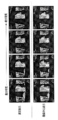
図14、図15に例示するように、動画再生に際して常に関心部位を含む断面画像が表示され、しかも関心部位の像が画面の特定位置に固定される。それにより全ての断面画像上で関心部位を好適に視認することができ、また視線移動が少なくなり、腫瘍の癒着などの診断に効果的である。
図7は第1の断面自動設定モードの説明図である。第1の断面自動決定モードでは、Z軸を基準軸として、基準軸に対して直交するXY面が断面として設定される。第1の断面自動設定モードの起動下では断面画像発生部115は一連のボリュームデータファイルから特定の単一のボリュームデータファイルを対象として例えばXY面に平行な原点を通る初期候補に関する断面画像を発生する。特定の単一のボリュームデータファイルとしては典型的には一連のボリュームデータファイルの中の中央時刻に最も近いボリュームデータファイルである。操作者は図示しない入力デバイスを介して候補断面をZ軸に沿って移動させながら関心部位の像が最も好適に映る断面を探索し、その断面画像上に当該関心部位内の点を指定する。
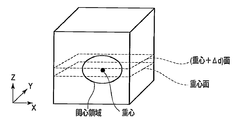
断面位置決定部125は、指定点の画素値又は指定点を中心とした局所範囲内の複数の画素に関する平均値又は中央値を閾値として、他のボリュームデータファイル各々から閾値処理により3次元の関心領域を抽出する。断面位置決定部125は、抽出された関心領域各々の内部に関心点を設定する。関心点には様々なバリアーションがある。関心点の一例は、図16に示すように、重心点、または重心点からZ軸方向に所定距離Δdだけ離れた点である。関心点の他の例は、図17に示すように、重心を通り、Z軸に平行であって、両端が関心領域エッジ上にある線分を所定の距離割合で分割する点である。関心点のさらに他の例は、図18に示すように、関心領域内の最大CT値又は最小CT値を有する画素の中心点に設定される。初期的には重心が設定されるが、操作者はこれら関心点から任意の一を選択することができる。なお、図16-図18で説明した関心点の設定方法は、図9-図11の血管や気管支に対する指定点の指定方法にも適用することができる。
関心点が設定された以後の断面決定及び動画再生処理は上述した手動設定モードで説明した処理と同じである。各ボリュームデータファイルに対して設定された関心点を含み、かつXY面に平行な断面(Z軸(基準軸)に直交する断面)が決定される。決定された断面に従ってボリュームデータファイルからMPR処理により断面画像が生成される。同様に、全てのボリュームデータファイルに対して断面画像が生成される。複数の断面画像は、再生コントローラ118による読み出し制御のもとで順方向再生と逆方向再生とが交互に繰り返される。
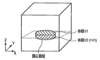
なお、関心点に代えて、図19に示すように、抽出された関心領域の体積を2等分するXY面を探索し、そのXY面(断面)に従ってボリュームデータファイルから断面画像を生成するようにしてもよい。
この第1の断面自動設定モードは手動設定モードと同様に関心部位が腫瘍等の一塊形状であるときに好適である。
図8は第2の断面自動設定モードの説明図である。第2の断面自動決定モードは、Z軸を基準軸として、基準軸に対して斜めに交差するオブリーク面を断面として設定することを許容する。第2の断面自動設定モードは対象が気管支や血管等の管状部位であるときに好適である。断面位置決定部125により一連のボリュームデータファイル各々から閾値処理により例えば血管領域が抽出される。抽出された血管領域に対して図9に示すように狭窄等を含む関心区間がその両端の2点を操作者が指定することにより設定される。断面位置決定部125により、指定された2点を通る、抽出された血管領域の血管芯線が特定される。指定された2点間の血管芯線を包含するように、断面位置、XYZ各軸に対するオブリーク角、さらに断面厚が断面位置決定部125により複数のボリュームデータファイルそれぞれについて個々に決定される。
断面決定以後の断面画像発生処理及び動画再生処理は上述した手動設定モードで説明した処理に略等価である。本モードでは、断面に垂直な方向(レイ)に沿って複数のボクセル値を積分し又は同一レイ上の複数のボクセル値から最大値を抽出する等により断面画像が発生される。複数のボリュームデータファイルそれぞれ対して決定された断面に従って複数の断面画像が生成される。複数の断面画像は、再生コントローラ118による読み出し制御のもとで順方向再生と逆方向再生とが交互に繰り返される。
この第2の断面自動設定モードでは、心臓の冠状動脈などの複雑に屈曲した血管等の関心区間全体を常に画面上で視認することができる。
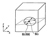
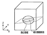
オブリーク断面を規定する第2の断面自動設定モードは、一塊形状を有する腫瘍等に対しても適用可能である。この場合、オブリーク断面は、図20に示すように、抽出された関心領域の重心を通り、両端が関心領域エッジ上にある線分の距離(直径)のうち、例えば最大径と最小径、又は最大径と2番目に長い径を示す2つの線分により規定される面に設定される。他の例では、オブリーク断面は、図21に示すように、抽出された関心領域の断面積が最大を示す断面に設定される。
図10は第3の断面自動設定モードの説明図である。第3の断面自動設定モードもその対象が気管支や血管等の管状部位であるときに好適である。断面位置決定部125により一連のボリュームデータファイル各々から閾値処理により例えば血管領域が抽出される。抽出された血管領域に対して図11に示すように狭窄等を含む関心区間がその両端の2点を操作者が指定することにより設定される。なお、血管の例えば末梢側の1点を操作者が指定し、血管上部まで自動的にトレースし、血管末梢と血管上部との間に関心区間を設定するようにしても良い。
断面位置決定部125により、指定された2点を通る、抽出された血管領域の血管芯線が特定される。指定された2点間の血管芯線のXY面への投影像に沿って、XY面に垂直な断面を、XY面に垂直な状態を維持したままで湾曲する。それにより複数のボリュームデータファイルそれぞれについて個々に断面(湾曲断面)決定される。
断面決定以後の断面画像発生処理及び動画再生処理は上述した手動設定モードで説明した処理に同様である。複数のボリュームデータファイルそれぞれ対して決定された湾曲断面に従って複数のボリュームデータファイルにそれぞれ対応する複数の断面画像が生成され、再生コントローラ118による読み出し制御のもとで順方向再生と逆方向再生とが交互に繰り返される。
この第3の断面自動設定モードでは、第2の断面自動設定モードのそれよりもより詳細な状態で複雑に屈曲した血管等の関心区間全体を常に画面上で視認することができる。
なお、第2、第3の断面自動設定モードで発生される断面画像上で複雑に走行する血管の像が図12に示すように直線的になるように断面画像発生部115により座標変換により変形するようにしてもよい。座標変換の一例としては、図13に示すように、血管芯線に対して中心で直交する複数の線分を配置し、複数の線分上の複数の画素列を直交座標系に再配置する。
本発明のいくつかの実施形態を説明したが、これらの実施形態は、例として提示したものであり、発明の範囲を限定することは意図していない。これら実施形態は、その他の様々な形態で実施されることが可能であり、発明の要旨を逸脱しない範囲で、種々の省略、置き換え、変更を行うことができる。これら実施形態やその変形は、発明の範囲や要旨に含まれると同様に、特許請求の範囲に記載された発明とその均等の範囲に含まれるものである。
100…架台部、101…X線管、102…回転フレーム、103…2次元検出器、104…データ収集装置、106…前処理装置、107…架台駆動部、109…高電圧発生器、110…ホストコントローラ、112…投影データ記憶部、113…ボリュームデータファイル記憶部、115…断面画像発生部、116…コーンビーム再構成処理部、117…表示部(ディスプレイ)、118…再生コントローラ、120…呼吸センサ、121…呼吸波形記憶部、123…最大値/最小値特定部、125…断面位置決定部。
Claims (19)
- 被検体の3次元領域に関する一連のボリュームデータファイルを記憶する記憶部と、
前記一連のボリュームデータファイルから一連の断面画像を発生する画像発生部と、
前記断面画像にそれぞれ対応する複数の断面を、前記複数のボリュームデータファイルに含まれる同一部位の位置に基づいて個々に決定する断面決定部とを具備する医用画像処理装置。 - 前記断面決定部は、前記複数のボリュームデータファイルから抽出した関心領域に基づいて前記複数の断面を決定する請求項1記載の医用画像処理装置。
- 前記複数の断面は基準軸に対して直交する請求項1記載の医用画像処理装置。
- 前記断面決定部は、前記ボリュームデータファイルから抽出した関心領域の重心を含む面を前記断面として決定する請求項1記載の医用画像処理装置。
- 前記断面決定部は、前記ボリュームデータファイルから抽出した関心領域の重心から所定方向に所定距離だけ離れた点を含む面を前記断面として決定する請求項1記載の医用画像処理装置。
- 前記断面決定部は、前記ボリュームデータファイルから抽出した関心領域内の最大画素値又は最小画素値を示す画素を含む面を前記断面として決定する請求項1記載の医用画像処理装置。
- 前記断面決定部は、前記ボリュームデータファイルから抽出した関心領域を体積等分する面を前記断面として決定する請求項1記載の医用画像処理装置。
- 前記複数の断面は基準軸に対してオブリークに設定される請求項1記載の医用画像処理装置。
- 前記断面決定部は、前記各ボリュームデータファイルから抽出した管状領域の芯線を含む面を前記断面として決定する請求項1記載の医用画像処理装置。
- 前記断面決定部は、前記各ボリュームデータファイルから抽出した管状領域の芯線を含むように前記断面の位置、方向及び断面厚を決定する請求項1記載の医用画像処理装置。
- 前記断面決定部は、前記ボリュームデータファイルから抽出した関心領域を体積等分する面を前記断面として決定する請求項1記載の医用画像処理装置。
- 前記断面決定部は、前記ボリュームデータファイルから抽出した関心領域の最大断面積を示す面を前記断面として決定する請求項1記載の医用画像処理装置。
- 前記断面決定部は、前記各ボリュームデータファイルから抽出した管状領域の芯線に従って湾曲面を前記断面として決定する請求項1記載の医用画像処理装置。
- 前記断面は、前記複数のボリュームデータファイルそれぞれに対して個々に手動で設定される請求項1記載の医用画像処理装置。
- 前記断面は、前記複数のボリュームデータファイルの中の少なくとも2のボリュームデータファイルに対して手動で設定された断面の位置に基づいて補間処理により決定される請求項1記載の医用画像処理装置。
- 前記被検体の3次元領域を対象として第1周期で繰り返し収集されたデータを記憶するデータ記憶部と、
前記収集されたデータに基づいて前記第1周期より短い第2周期で前記一連のボリュームデータファイルを発生するボリュームデータ発生部とをさらに備える請求項1記載の医用画像処理装置。 - 前記一連の断面画像を動画として順方向と逆方向とで交互に再生表示する表示部をさらに備える請求項1記載の医用画像処理装置。
- 前記表示される一連の断面画像は、操作者により指定された関心領域部位の位置を表示画面の同一位置に固定するために前記2次元画像の表示位置を個々に制御する請求項1記載の医用画像処理装置。
- 被検体の3次元領域に関する投影データを繰り返し収集する収集部と、
前記投影データから一連のボリュームデータファイルを再構成する再構成部と、
前記再構成された一連のボリュームデータファイルから一連の断面画像を発生する画像発生部と、
前記断面画像にそれぞれ対応する複数の断面を、前記複数のボリュームデータファイルに含まれる同一部位の位置に基づいて個々に決定する断面決定部とを具備するX線コンピュータ断層撮影装置。
Priority Applications (2)
| Application Number | Priority Date | Filing Date | Title |
|---|---|---|---|
| CN201180002863.7A CN102573642B (zh) | 2010-10-15 | 2011-10-13 | 医用图像处理装置以及x射线计算机断层摄影装置 |
| US13/323,866 US8798227B2 (en) | 2010-10-15 | 2011-12-13 | Medical image processing apparatus and X-ray computed tomography apparatus |
Applications Claiming Priority (2)
| Application Number | Priority Date | Filing Date | Title |
|---|---|---|---|
| JP2010232826 | 2010-10-15 | ||
| JP2010-232826 | 2010-10-15 |
Related Child Applications (1)
| Application Number | Title | Priority Date | Filing Date |
|---|---|---|---|
| US13/323,866 Continuation US8798227B2 (en) | 2010-10-15 | 2011-12-13 | Medical image processing apparatus and X-ray computed tomography apparatus |
Publications (1)
| Publication Number | Publication Date |
|---|---|
| WO2012050166A1 true WO2012050166A1 (ja) | 2012-04-19 |
Family
ID=45938390
Family Applications (1)
| Application Number | Title | Priority Date | Filing Date |
|---|---|---|---|
| PCT/JP2011/073556 Ceased WO2012050166A1 (ja) | 2010-10-15 | 2011-10-13 | 医用画像処理装置及びx線コンピュータ断層撮影装置 |
Country Status (3)
| Country | Link |
|---|---|
| JP (1) | JP5984237B2 (ja) |
| CN (1) | CN102573642B (ja) |
| WO (1) | WO2012050166A1 (ja) |
Families Citing this family (2)
| Publication number | Priority date | Publication date | Assignee | Title |
|---|---|---|---|---|
| JP2015150325A (ja) * | 2014-02-18 | 2015-08-24 | 株式会社東芝 | 医用画像処理装置及び医用画像処理方法 |
| JP6528386B2 (ja) * | 2014-11-04 | 2019-06-12 | 富士通株式会社 | 画像処理装置、画像処理方法及び画像処理プログラム |
Citations (10)
| Publication number | Priority date | Publication date | Assignee | Title |
|---|---|---|---|---|
| JPH11328433A (ja) * | 1996-01-31 | 1999-11-30 | Mitsubishi Electric Corp | 動画アンカ―設定装置およびその装置を用いた動画ハイパ―メディア装置と動画提供システム |
| JP2000201921A (ja) * | 1999-01-13 | 2000-07-25 | Toshiba Corp | X線コンピュ―タ断層撮影装置 |
| JP2005204959A (ja) * | 2004-01-23 | 2005-08-04 | Canon Inc | 連続フレーム画像表示装置 |
| JP2006068350A (ja) * | 2004-09-03 | 2006-03-16 | Toshiba Corp | 医用画像表示方法、医用画像表示装置及び医用画像表示のためのプログラム |
| JP2007260391A (ja) * | 2006-03-01 | 2007-10-11 | Toshiba Corp | 画像処理装置 |
| JP2007282945A (ja) * | 2006-04-19 | 2007-11-01 | Toshiba Corp | 画像処理装置 |
| JP2009000153A (ja) * | 2007-06-19 | 2009-01-08 | Fujifilm Corp | 画像診断支援装置、方法及びプログラム |
| WO2009096290A1 (ja) * | 2008-01-31 | 2009-08-06 | Hitachi Medical Corporation | 医用画像診断装置及び方法 |
| JP2009207541A (ja) * | 2008-02-29 | 2009-09-17 | Toshiba Corp | 医用画像読影支援装置 |
| JP2011120825A (ja) * | 2009-12-14 | 2011-06-23 | Fujifilm Corp | 医用画像表示装置および方法並びにプログラム |
Family Cites Families (12)
| Publication number | Priority date | Publication date | Assignee | Title |
|---|---|---|---|---|
| US5970504A (en) * | 1996-01-31 | 1999-10-19 | Mitsubishi Denki Kabushiki Kaisha | Moving image anchoring apparatus and hypermedia apparatus which estimate the movement of an anchor based on the movement of the object with which the anchor is associated |
| US6363134B1 (en) * | 1999-01-13 | 2002-03-26 | Kabushiki Kaisha Toshiba | X-ray computed tomography apparatus |
| EP1188148A2 (en) * | 2000-01-27 | 2002-03-20 | Koninklijke Philips Electronics N.V. | Method and system for extracting spine geometrical data |
| JP4564233B2 (ja) * | 2003-01-31 | 2010-10-20 | 株式会社東芝 | 画像処理装置、画像データ処理方法、及びプログラム |
| JP4421203B2 (ja) * | 2003-03-20 | 2010-02-24 | 株式会社東芝 | 管腔状構造体の解析処理装置 |
| JP4629415B2 (ja) * | 2004-11-26 | 2011-02-09 | 株式会社日立メディコ | 画像表示システム、画像表示方法及び画像表示プログラム |
| JP4703193B2 (ja) * | 2005-01-14 | 2011-06-15 | 株式会社東芝 | 画像処理装置 |
| US8731367B2 (en) * | 2006-03-01 | 2014-05-20 | Kabushiki Kaisha Toshiba | Image processing apparatus |
| US8107701B2 (en) * | 2006-03-29 | 2012-01-31 | Hitachi Medical Corporation | Medical image display system and medical image display program |
| JP5591440B2 (ja) * | 2007-01-17 | 2014-09-17 | 株式会社東芝 | 医用画像表示装置 |
| JP5364334B2 (ja) * | 2008-10-24 | 2013-12-11 | 株式会社東芝 | 医用画像処理装置 |
| JP5414249B2 (ja) * | 2008-11-25 | 2014-02-12 | 株式会社東芝 | 画像表示装置 |
-
2011
- 2011-10-13 CN CN201180002863.7A patent/CN102573642B/zh active Active
- 2011-10-13 WO PCT/JP2011/073556 patent/WO2012050166A1/ja not_active Ceased
- 2011-10-13 JP JP2011225405A patent/JP5984237B2/ja active Active
Patent Citations (10)
| Publication number | Priority date | Publication date | Assignee | Title |
|---|---|---|---|---|
| JPH11328433A (ja) * | 1996-01-31 | 1999-11-30 | Mitsubishi Electric Corp | 動画アンカ―設定装置およびその装置を用いた動画ハイパ―メディア装置と動画提供システム |
| JP2000201921A (ja) * | 1999-01-13 | 2000-07-25 | Toshiba Corp | X線コンピュ―タ断層撮影装置 |
| JP2005204959A (ja) * | 2004-01-23 | 2005-08-04 | Canon Inc | 連続フレーム画像表示装置 |
| JP2006068350A (ja) * | 2004-09-03 | 2006-03-16 | Toshiba Corp | 医用画像表示方法、医用画像表示装置及び医用画像表示のためのプログラム |
| JP2007260391A (ja) * | 2006-03-01 | 2007-10-11 | Toshiba Corp | 画像処理装置 |
| JP2007282945A (ja) * | 2006-04-19 | 2007-11-01 | Toshiba Corp | 画像処理装置 |
| JP2009000153A (ja) * | 2007-06-19 | 2009-01-08 | Fujifilm Corp | 画像診断支援装置、方法及びプログラム |
| WO2009096290A1 (ja) * | 2008-01-31 | 2009-08-06 | Hitachi Medical Corporation | 医用画像診断装置及び方法 |
| JP2009207541A (ja) * | 2008-02-29 | 2009-09-17 | Toshiba Corp | 医用画像読影支援装置 |
| JP2011120825A (ja) * | 2009-12-14 | 2011-06-23 | Fujifilm Corp | 医用画像表示装置および方法並びにプログラム |
Also Published As
| Publication number | Publication date |
|---|---|
| CN102573642B (zh) | 2015-08-19 |
| JP2012101045A (ja) | 2012-05-31 |
| CN102573642A (zh) | 2012-07-11 |
| JP5984237B2 (ja) | 2016-09-06 |
Similar Documents
| Publication | Publication Date | Title |
|---|---|---|
| US8798227B2 (en) | Medical image processing apparatus and X-ray computed tomography apparatus | |
| JP5897273B2 (ja) | 医用画像表示装置及びx線コンピュータ断層撮影装置 | |
| CN1915170B (zh) | 对生物的运动身体部位产生图像的方法和放射线诊断装置 | |
| JP4346297B2 (ja) | X線コンピュータ断層撮影装置、画像処理装置及び画像処理方法 | |
| JP4495109B2 (ja) | X線ct装置 | |
| JP5390132B2 (ja) | X線ct装置 | |
| JP5317580B2 (ja) | X線ct装置 | |
| JP5777317B2 (ja) | 医用画像表示装置 | |
| US8731367B2 (en) | Image processing apparatus | |
| US10238355B2 (en) | Tomography apparatus and method of reconstructing tomography image thereof | |
| US20120099776A1 (en) | Medical image processing apparatus | |
| JP4928739B2 (ja) | X線診断装置及びx線撮像方法 | |
| JP5743445B2 (ja) | 放射線コンピュータ断層撮影装置、医用画像発生装置及び呼吸位相計測装置 | |
| WO2004071301A1 (ja) | X線ct装置 | |
| JP5984237B2 (ja) | 医用画像処理装置及びx線コンピュータ断層撮影装置 | |
| CN103284749B (zh) | 医用图像处理装置 | |
| JP6933498B2 (ja) | 医用情報処理装置、x線ct装置及び医用情報処理プログラム | |
| CN103284748A (zh) | 医用图像处理装置 | |
| JP4266422B2 (ja) | 放射線断層撮影方法および装置 | |
| JP2024121393A (ja) | X線コンピュータ断層撮影装置 | |
| JP6068177B2 (ja) | 医用画像診断装置、医用画像処理装置及び医用画像処理方法 | |
| JP5689925B2 (ja) | X線ct装置 | |
| JP7191235B2 (ja) | 適応型ヘリカルコンピュータ断層撮影 | |
| JP2007135668A (ja) | X線ct装置 | |
| KR20160072004A (ko) | 단층 촬영 장치 및 그에 따른 단층 영상 복원 방법 |
Legal Events
| Date | Code | Title | Description |
|---|---|---|---|
| WWE | Wipo information: entry into national phase |
Ref document number: 201180002863.7 Country of ref document: CN |
|
| 121 | Ep: the epo has been informed by wipo that ep was designated in this application |
Ref document number: 11832597 Country of ref document: EP Kind code of ref document: A1 |
|
| NENP | Non-entry into the national phase |
Ref country code: DE |
|
| 122 | Ep: pct application non-entry in european phase |
Ref document number: 11832597 Country of ref document: EP Kind code of ref document: A1 |