WO2012046398A1 - ドーム型カメラおよび絞り制御方法 - Google Patents
ドーム型カメラおよび絞り制御方法 Download PDFInfo
- Publication number
- WO2012046398A1 WO2012046398A1 PCT/JP2011/005275 JP2011005275W WO2012046398A1 WO 2012046398 A1 WO2012046398 A1 WO 2012046398A1 JP 2011005275 W JP2011005275 W JP 2011005275W WO 2012046398 A1 WO2012046398 A1 WO 2012046398A1
- Authority
- WO
- WIPO (PCT)
- Prior art keywords
- dome
- camera lens
- camera
- value
- reference value
- Prior art date
- Legal status (The legal status is an assumption and is not a legal conclusion. Google has not performed a legal analysis and makes no representation as to the accuracy of the status listed.)
- Ceased
Links
Images


Classifications
-
- G—PHYSICS
- G03—PHOTOGRAPHY; CINEMATOGRAPHY; ANALOGOUS TECHNIQUES USING WAVES OTHER THAN OPTICAL WAVES; ELECTROGRAPHY; HOLOGRAPHY
- G03B—APPARATUS OR ARRANGEMENTS FOR TAKING PHOTOGRAPHS OR FOR PROJECTING OR VIEWING THEM; APPARATUS OR ARRANGEMENTS EMPLOYING ANALOGOUS TECHNIQUES USING WAVES OTHER THAN OPTICAL WAVES; ACCESSORIES THEREFOR
- G03B7/00—Control of exposure by setting shutters, diaphragms or filters, separately or conjointly
- G03B7/08—Control effected solely on the basis of the response, to the intensity of the light received by the camera, of a built-in light-sensitive device
- G03B7/091—Digital circuits
- G03B7/095—Digital circuits for control of aperture
-
- G—PHYSICS
- G03—PHOTOGRAPHY; CINEMATOGRAPHY; ANALOGOUS TECHNIQUES USING WAVES OTHER THAN OPTICAL WAVES; ELECTROGRAPHY; HOLOGRAPHY
- G03B—APPARATUS OR ARRANGEMENTS FOR TAKING PHOTOGRAPHS OR FOR PROJECTING OR VIEWING THEM; APPARATUS OR ARRANGEMENTS EMPLOYING ANALOGOUS TECHNIQUES USING WAVES OTHER THAN OPTICAL WAVES; ACCESSORIES THEREFOR
- G03B37/00—Panoramic or wide-screen photography; Photographing extended surfaces, e.g. for surveying; Photographing internal surfaces, e.g. of pipe
- G03B37/02—Panoramic or wide-screen photography; Photographing extended surfaces, e.g. for surveying; Photographing internal surfaces, e.g. of pipe with scanning movement of lens or cameras
-
- H—ELECTRICITY
- H04—ELECTRIC COMMUNICATION TECHNIQUE
- H04N—PICTORIAL COMMUNICATION, e.g. TELEVISION
- H04N23/00—Cameras or camera modules comprising electronic image sensors; Control thereof
- H04N23/50—Constructional details
-
- H—ELECTRICITY
- H04—ELECTRIC COMMUNICATION TECHNIQUE
- H04N—PICTORIAL COMMUNICATION, e.g. TELEVISION
- H04N23/00—Cameras or camera modules comprising electronic image sensors; Control thereof
- H04N23/60—Control of cameras or camera modules
- H04N23/695—Control of camera direction for changing a field of view, e.g. pan, tilt or based on tracking of objects
-
- H—ELECTRICITY
- H04—ELECTRIC COMMUNICATION TECHNIQUE
- H04N—PICTORIAL COMMUNICATION, e.g. TELEVISION
- H04N23/00—Cameras or camera modules comprising electronic image sensors; Control thereof
- H04N23/70—Circuitry for compensating brightness variation in the scene
- H04N23/75—Circuitry for compensating brightness variation in the scene by influencing optical camera components
Definitions
- the present invention relates to a technique for improving image quality in a dome type camera.
- dome cameras also referred to as megapixel dome cameras
- megapixel dome cameras having megapixel (1280 ⁇ 960 pixel) class image quality
- megapixel dome camera even a slight defocus that is not a problem with a conventional VGA dome camera is a problem of image quality degradation. Therefore, conventionally, development of technology for improving image quality in megapixel dome cameras has been desired.
- An object of the present invention is to provide a dome type camera that can obtain a high-quality image even with a megapixel dome camera.
- the dome type camera includes a camera lens that can be rotated in a tilt direction, a dome cover that covers the camera lens, and a diaphragm control unit that controls a diaphragm amount of the camera lens, and is used as a reference for the diaphragm amount.
- the reference value is set so that the angle in the tilt direction of the camera lens decreases from the open value to the close value as the angle of the camera lens decreases from the zenith direction to the horizontal direction.
- Another aspect of the present invention is a diaphragm control method.
- This diaphragm control method is used in a dome type camera including a camera lens that can rotate in a tilt direction, a dome cover that covers the camera lens, and a diaphragm control unit that controls a diaphragm amount of the camera lens.
- the angle of the tilt direction is detected, and the aperture amount is controlled so that it decreases from the open value to the close value as the tilt direction angle decreases from the zenith direction of the dome cover toward the horizontal direction. .
- FIG. 1 is a block diagram of a dome type camera according to an embodiment of the present invention.
- FIG. 2 is a schematic diagram of a dome type camera (high tilt angle state) in the embodiment of the present invention.
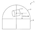
- FIG. 3 is a schematic diagram of a dome type camera (low tilt angle state) in the embodiment of the present invention.
- FIG. 4 is a diagram showing the relationship between the tilt angle and the aperture amount (first reference value) in the embodiment of the present invention.
- FIG. 5 is a diagram showing the relationship between the zoom magnification and the aperture amount (second reference value) in the embodiment of the present invention.
- FIG. 6 is a diagram showing the relationship between the illuminance and the aperture amount (third reference value) in the embodiment of the present invention.
- FIG. 7 is a diagram showing the relationship between the offset amount and the tilt angle in the embodiment of the present invention.
- this dome type camera has an aperture control, this function may be realized by a program stored in a memory or the like of the dome type camera.
- a dome type camera of the present invention is a dome type camera comprising a camera lens that can be rotated in a tilt direction, a dome cover that covers the camera lens, and an aperture control unit that controls an aperture amount of the camera lens,
- the first reference value used as a reference for the aperture amount decreases from the open value to the closed value as the tilt angle of the camera lens decreases from the zenith direction to the horizontal direction of the dome cover. It has the structure set to.
- the dome type camera of the present invention further includes a zoom control unit that controls the zoom magnification of the camera lens, and the second reference value used as a reference for the aperture amount is an open value as the zoom magnification increases.
- the aperture value may be set so as to decrease toward the close value, and the aperture amount may be set using the first reference value and the second reference value.
- the diaphragm amount of the camera lens is controlled to be decreased accordingly.
- the defocus due to the uneven thickness of the dome cover becomes more prominent.
- the defocus can be reduced by reducing the aberration by reducing the aperture of the camera lens. Can be reduced.
- the aperture amount of the camera lens is set to the smaller one of the first reference value set based on the tilt angle and the second reference value set based on the zoom magnification, the aperture amount Can be suppressed from becoming excessively small.
- the dome type camera of the present invention further includes an illuminance measuring unit that measures the illuminance of incident light of the camera lens, and the third reference value used as a reference for the aperture amount is closed as the illuminance decreases.
- the aperture value is set so as to increase toward the open value, and the aperture amount is compared with the value set using the first reference value and the second reference value and the third reference value, whichever is larger You may have the structure set to a value.
- the aperture amount of the camera lens is controlled to increase accordingly. Thereby, it can suppress that the amount of diaphragms becomes too small. Therefore, a highly sensitive image can be obtained even in a shooting environment with low illuminance (dark shooting environment).
- the camera lens can offset the optical axis of the camera lens from the center position of the dome cover in the zenith direction, and the offset amount of the camera lens is the zenith of the dome cover. It may have a configuration that is set to increase from the center position of the dome cover toward the zenith direction as it decreases from the direction toward the horizontal direction.
- the diaphragm control method of the present invention is a diaphragm used in a dome type camera including a camera lens that can be rotated in a tilt direction, a dome cover that covers the camera lens, and a diaphragm control unit that controls a diaphragm amount of the camera lens.
- the control method detects the angle of the camera lens in the tilt direction, and the aperture amount is changed from the open value to the close value as the tilt direction angle decreases from the zenith direction of the dome cover toward the horizontal direction. Control to become smaller.
- the amount of defocusing can be reduced by reducing the aberration by reducing the aperture amount of the camera lens. Therefore, even with a megapixel dome camera, it is possible to obtain a good low tilt angle image with reduced out-of-focus.
- dome type camera According to an embodiment of the present invention, a case of a high-quality camera of a megapixel (1280 ⁇ 960 pixels) class, which is a dome type camera used for a surveillance camera or the like is illustrated.
- FIG. 1 is a block diagram showing a main configuration of the dome type camera of the present embodiment
- FIGS. 2 and 3 are schematic views schematically showing the dome type camera.
- the dome type camera 1 includes a lens unit 2 that can be rotated in a pan direction and a tilt direction, a dome cover 3 that covers the lens unit 2, a CPU, a microcomputer, and the like. Part 4 is provided.
- the lens unit 2 includes an image sensor 5 such as a CCD or CMOS, a camera lens 6 disposed on the front side (left side in FIG. 1) of the image sensor 5, and an optical path of the camera lens 6.
- the aperture mechanism 7 is provided.
- the lens unit 2 includes a pan / tilt mechanism for rotating the lens unit 2 in the pan direction and the tilt direction, and the lens unit 2 facing the zenith direction of the dome cover 3.
- An offset mechanism for offsetting is provided.
- the dome cover 3 is attached to the base portion 8 so as to cover the lens unit 2.
- the dome cover 3 is made of a transparent plastic such as polycarbonate and has sufficient strength and light resistance.
- the shape of the dome cover 3 is a hemisphere, and the center (sphere center) of the dome cover 3 and the optical axis coincide with each other.
- the lens unit 2 is disposed at the center of the dome cover 3 without being offset (see FIG. 2).
- the lens unit 2 is offset, the lens unit 2 is displaced from the center position of the dome cover 3 in the zenith direction (see FIG. 3).
- the amount of deviation (the amount of deviation from the center position) is referred to as an offset amount.
- the angle (tilt angle) in the tilt direction of the camera lens 6 is an angle formed by the horizontal direction of the dome cover 3 and the optical axis of the camera lens 6. Therefore, when the lens unit 2 (camera lens 6) is oriented in the horizontal direction, the tilt angle is 0 degree, and when the lens unit 2 (camera lens 6) is oriented in the zenith direction, the tilt angle is 90 degrees. Degree (see FIG. 2).
- the control unit 4 includes an aperture control unit 9 that controls the aperture amount of the camera lens 6, a zoom control unit 10 that controls the zoom magnification of the camera lens 6, and the illuminance of incident light from the camera lens 6.
- An illuminance measuring unit 11 that measures the above is provided.
- the aperture control unit 9 has a function of controlling the aperture amount of the camera lens 6 by adjusting the aperture amount of the aperture mechanism 7.
- the zoom control unit 10 has a function of controlling the zoom magnification of the camera lens 6 by moving the camera lens 6 back and forth along the optical axis direction.
- the illuminance measurement unit 11 has a function of measuring illuminance based on an output signal from the image sensor 5.
- control unit 4 includes a tilt control unit 12 that controls the rotation of the lens unit 2 in the tilt direction, and an offset control unit 13 that controls the offset movement of the lens unit 2 in the zenith direction.
- the tilt control unit 12 has a function of rotating the lens unit 2 in the tilt direction by controlling the pan / tilt mechanism.
- the offset control unit 13 has a function of offsetting the lens unit 2 toward the zenith direction of the dome cover 3 by controlling the offset mechanism.
- the aperture amount is set based on three reference values (first reference value, second reference value, and third reference value).
- the first reference value of the aperture amount is set based on the tilt angle of the lens unit 2 (tilt angle of the camera lens 6).
- the tilt angle is detected by the tilt control unit 12.
- FIG. 4 is a diagram illustrating the relationship between the tilt angle and the first reference value of the aperture amount.
- the first reference value of the aperture amount is set so as to decrease from the open value (100%) toward the close value (0%) as the tilt angle decreases. For example, in the example of FIG. 4, when the tilt angle is between 90 degrees and 45 degrees, the aperture amount is set to 100%, and when the tilt angle is between 45 degrees and 0 degrees, the aperture amount is between 100% and 50%. When the tilt angle is smaller than 0 degrees, the aperture amount is set to 50%.
- the tilt angle range (the tilt angle range where the aperture amount decreases) is limited to this. Absent.
- the case has been described in which the aperture amount changes linearly (linear function) from 100% to 50% when the tilt angle is 45 ° to 0 °. This is not limited to this.
- the second reference value of the aperture amount is set based on the zoom magnification of the camera lens 6.
- the zoom magnification is detected by the zoom control unit 10.
- FIG. 5 is a diagram illustrating a relationship between the zoom magnification and the second reference value of the aperture amount.
- the second reference value of the aperture amount is set so as to decrease from the open value (100%) to the close value (0%) as the zoom magnification increases.
- the aperture amount is set to 100% when the zoom magnification is 1 to 9 times, and the aperture amount is 100% to 50 when the zoom magnification is 9 to 15 times.
- the aperture amount is set to 50%.
- the zoom magnification range zoom magnification range in which the aperture amount decreases
- Absent In the example of FIG. 5, the case has been described where the aperture amount changes linearly (linear function) from 100% to 50% while the zoom magnification is from 1 to 9 times. This is not limited to this.
- the third reference value of the aperture amount is set based on the illuminance of the incident light from the camera lens 6.
- the illuminance is measured by the illuminance measurement unit 11.
- FIG. 6 is a diagram illustrating the relationship between the illuminance and the third reference value of the aperture amount.
- the third reference value of the aperture amount is set so as to increase from the close value (0%) to the open value (100%) as the illuminance decreases. For example, in the example of FIG. 6, when the illuminance is 10 lux to 1 lux, the aperture amount is set to 50%, and when the illuminance is 1 lux to 0.1 lux, the aperture amount is 50% to 100%. Set to gradually increase to%.
- the aperture amount decreases when the illuminance range is 1 lux to 0.1 lux, but the illuminance range (the illuminance range where the aperture amount decreases) is not limited thereto. . Further, in the example of FIG. 6, a case has been described in which the aperture amount changes linearly (linear function) from 50% to 100% while the illuminance is from 1 lux to 0.1 lux. The way of change is not limited to this.
- the aperture amount is set based on these three reference values (first reference value, second reference value, and third reference value). Specifically, the smaller one of the first reference value and the second reference value is compared with the third reference value, and the larger value is set. For example, when the first reference value is 75%, the second reference value is 50%, and the third reference value is 90%, the aperture amount is the smaller of the first reference value and the second reference value. The value (50%) and the third reference value (90%) are compared, and the larger value (90%) is set.
- the aperture amount may be set based on two reference values (for example, a first reference value and a second reference value).
- the first reference value and the second reference value are compared and set to the smaller value.
- the aperture amount is reduced to a smaller value (50%) by comparing the first reference value and the second reference value. Is set.
- the aperture amount may be set based on one reference value (for example, only the first reference value).
- FIG. 7 is a diagram illustrating the relationship between the tilt angle and the offset amount.
- the offset amount is set to increase from the center position (0 mm) of the dome cover 3 toward the zenith direction as the tilt angle decreases.
- the offset amount is set to 0 mm when the tilt angle is 90 degrees to 30 degrees
- the offset amount is set to 0 mm to 30 mm when the tilt angle is 30 degrees to ⁇ 30 degrees. It is set to increase gradually.
- the tilt angle range (the tilt angle range where the offset amount decreases) is limited to this. I can't.
- the case where the offset amount changes linearly (linear function) from 0 mm to 30 mm while the tilt angle is between 30 degrees and ⁇ 30 degrees has been described. The way is not limited to this.
- dome type camera 1 of the embodiment of the present invention as described above, a good low tilt angle image with reduced out-of-focus can be obtained even with a megapixel dome camera.
- the aperture amount of the camera lens 6 is controlled to be reduced accordingly.
- the focus is reduced by reducing the aberration by reducing the aperture amount of the camera lens 6.
- Blur can be reduced. In this way, even with a megapixel dome camera, it is possible to obtain a good low tilt angle image with reduced out-of-focus.
- the diaphragm amount of the camera lens 6 is controlled to be decreased accordingly.
- the zoom magnification increases, the blur due to the non-uniformity of the thickness of the dome cover 3 becomes more prominent.
- the focus is reduced by reducing the aberration by reducing the aperture amount of the camera lens 6.
- Blur can be reduced. In this way, even with a megapixel dome camera, it is possible to obtain a good low tilt angle image with reduced out-of-focus.
- the aperture amount of the camera lens 6 is set to the smaller one of the first reference value set based on the tilt angle and the second reference value set based on the zoom magnification. Therefore, it is possible to prevent the aperture amount from becoming excessively small.
- the aperture amount of the camera lens 6 is controlled to be increased accordingly. Therefore, it can suppress that the amount of diaphragms becomes too small. Therefore, a highly sensitive image can be obtained even in a shooting environment with low illuminance (dark shooting environment).
- the aperture amount is set to the smaller one of the first reference value and the second reference value.
- the aperture amount may be set to the larger one of the first reference value and the second reference value.
- the dome-type camera according to the present invention has the effect of being able to obtain a good low tilt angle image with reduced out-of-focus even with a megapixel dome camera, and is useful as a surveillance camera or the like. .
Landscapes
- Engineering & Computer Science (AREA)
- Multimedia (AREA)
- Signal Processing (AREA)
- Physics & Mathematics (AREA)
- General Physics & Mathematics (AREA)
- Studio Devices (AREA)
- Accessories Of Cameras (AREA)
- Exposure Control For Cameras (AREA)
Priority Applications (3)
| Application Number | Priority Date | Filing Date | Title |
|---|---|---|---|
| EP11830332.0A EP2605063B1 (en) | 2010-10-08 | 2011-09-20 | Dome-type camera and aperture control method |
| US13/821,336 US9014549B2 (en) | 2010-10-08 | 2011-09-20 | Dome-type camera and aperture control method |
| CN2011900007782U CN203241687U (zh) | 2010-10-08 | 2011-09-20 | 穹顶型照相机 |
Applications Claiming Priority (2)
| Application Number | Priority Date | Filing Date | Title |
|---|---|---|---|
| JP2010228306A JP5834170B2 (ja) | 2010-10-08 | 2010-10-08 | ドーム型カメラおよび絞り制御方法 |
| JP2010-228306 | 2010-10-08 |
Publications (1)
| Publication Number | Publication Date |
|---|---|
| WO2012046398A1 true WO2012046398A1 (ja) | 2012-04-12 |
Family
ID=45927406
Family Applications (1)
| Application Number | Title | Priority Date | Filing Date |
|---|---|---|---|
| PCT/JP2011/005275 Ceased WO2012046398A1 (ja) | 2010-10-08 | 2011-09-20 | ドーム型カメラおよび絞り制御方法 |
Country Status (5)
| Country | Link |
|---|---|
| US (1) | US9014549B2 (https=) |
| EP (1) | EP2605063B1 (https=) |
| JP (1) | JP5834170B2 (https=) |
| CN (1) | CN203241687U (https=) |
| WO (1) | WO2012046398A1 (https=) |
Families Citing this family (7)
| Publication number | Priority date | Publication date | Assignee | Title |
|---|---|---|---|---|
| US9291880B2 (en) * | 2013-01-30 | 2016-03-22 | Spark Facter Design | Mobile device light meter attachment |
| JP6283909B2 (ja) * | 2013-03-01 | 2018-02-28 | パナソニックIpマネジメント株式会社 | カメラ装置及びカメラ装置の制御方法 |
| JP6211417B2 (ja) | 2013-12-27 | 2017-10-11 | 株式会社エーエスシー | 監視カメラ装置 |
| JP2015180044A (ja) * | 2014-02-28 | 2015-10-08 | パナソニックIpマネジメント株式会社 | ドームカメラ |
| JP6468744B2 (ja) | 2014-07-23 | 2019-02-13 | キヤノン株式会社 | 撮像装置、画像処理装置、撮像装置の画像処理方法、並びにプログラム |
| US10044932B2 (en) * | 2015-03-13 | 2018-08-07 | Sensormatic Electronics, LLC | Wide angle fisheye security camera having offset lens and image sensor |
| JP6080065B1 (ja) * | 2016-03-07 | 2017-02-15 | パナソニックIpマネジメント株式会社 | カメラ装置 |
Citations (6)
| Publication number | Priority date | Publication date | Assignee | Title |
|---|---|---|---|---|
| JPH08256288A (ja) * | 1995-03-17 | 1996-10-01 | Canon Inc | 撮像装置 |
| JPH0983841A (ja) * | 1995-09-06 | 1997-03-28 | Nisca Corp | テレビカメラ用の雲台構造、及び、パンチルトカメラ |
| JP2005300659A (ja) | 2004-04-07 | 2005-10-27 | Matsushita Electric Ind Co Ltd | ドーム型カメラおよびドームカバー |
| JP2009003010A (ja) * | 2007-06-19 | 2009-01-08 | Canon Inc | 雲台式カメラ装置 |
| JP2010008498A (ja) * | 2008-06-24 | 2010-01-14 | Canon Inc | 撮像装置 |
| JP2010048841A (ja) * | 2008-08-19 | 2010-03-04 | Olympus Corp | 顕微鏡対物レンズおよび拡大撮像装置 |
Family Cites Families (9)
| Publication number | Priority date | Publication date | Assignee | Title |
|---|---|---|---|---|
| US4833534A (en) * | 1988-02-19 | 1989-05-23 | Sensormatic Electronics Corporation | Surveillance assembly having enhanced shielding and reduced size |
| US6707500B1 (en) | 1995-03-17 | 2004-03-16 | Canon Kabushiki Kaisha | Image pickup apparatus with correction of held exposure parameters and lens spherical aberration correction |
| JP2004320526A (ja) * | 2003-04-17 | 2004-11-11 | Minolta Co Ltd | 撮像装置、撮像システム、及びプログラム |
| JP4284208B2 (ja) * | 2004-02-23 | 2009-06-24 | パナソニック株式会社 | チルト式カメラ装置 |
| KR100760544B1 (ko) * | 2005-04-18 | 2007-09-20 | 엘지전자 주식회사 | 기계적 조리개 및 셔터를 구비한 초소형 카메라 모듈 |
| JP4979285B2 (ja) * | 2006-07-07 | 2012-07-18 | パナソニック株式会社 | ドーム型監視カメラ装置 |
| JP4845931B2 (ja) * | 2008-06-13 | 2011-12-28 | 三菱電機株式会社 | ドーム型カメラ及びドームカバーの製造方法 |
| JP5223597B2 (ja) * | 2008-10-30 | 2013-06-26 | 株式会社Jvcケンウッド | 監視カメラ装置のチルト機構 |
| JP5431293B2 (ja) * | 2010-11-10 | 2014-03-05 | パナソニック株式会社 | ドーム型カメラ |
-
2010
- 2010-10-08 JP JP2010228306A patent/JP5834170B2/ja active Active
-
2011
- 2011-09-20 CN CN2011900007782U patent/CN203241687U/zh not_active Expired - Fee Related
- 2011-09-20 US US13/821,336 patent/US9014549B2/en active Active
- 2011-09-20 WO PCT/JP2011/005275 patent/WO2012046398A1/ja not_active Ceased
- 2011-09-20 EP EP11830332.0A patent/EP2605063B1/en not_active Not-in-force
Patent Citations (6)
| Publication number | Priority date | Publication date | Assignee | Title |
|---|---|---|---|---|
| JPH08256288A (ja) * | 1995-03-17 | 1996-10-01 | Canon Inc | 撮像装置 |
| JPH0983841A (ja) * | 1995-09-06 | 1997-03-28 | Nisca Corp | テレビカメラ用の雲台構造、及び、パンチルトカメラ |
| JP2005300659A (ja) | 2004-04-07 | 2005-10-27 | Matsushita Electric Ind Co Ltd | ドーム型カメラおよびドームカバー |
| JP2009003010A (ja) * | 2007-06-19 | 2009-01-08 | Canon Inc | 雲台式カメラ装置 |
| JP2010008498A (ja) * | 2008-06-24 | 2010-01-14 | Canon Inc | 撮像装置 |
| JP2010048841A (ja) * | 2008-08-19 | 2010-03-04 | Olympus Corp | 顕微鏡対物レンズおよび拡大撮像装置 |
Non-Patent Citations (1)
| Title |
|---|
| See also references of EP2605063A4 |
Also Published As
| Publication number | Publication date |
|---|---|
| EP2605063A1 (en) | 2013-06-19 |
| JP5834170B2 (ja) | 2015-12-16 |
| US20130272690A1 (en) | 2013-10-17 |
| JP2012083464A (ja) | 2012-04-26 |
| CN203241687U (zh) | 2013-10-16 |
| EP2605063B1 (en) | 2015-04-01 |
| US9014549B2 (en) | 2015-04-21 |
| EP2605063A4 (en) | 2013-09-25 |
Similar Documents
| Publication | Publication Date | Title |
|---|---|---|
| JP5834170B2 (ja) | ドーム型カメラおよび絞り制御方法 | |
| KR102560780B1 (ko) | 복수의 이미지 센서를 포함하는 이미지 처리 시스템 및 그것을 포함하는 전자 장치 | |
| US10244170B2 (en) | Image-shake correction apparatus and control method thereof | |
| TWI720445B (zh) | 攝像機裝置中圖像融合的方法及相關裝置 | |
| US10122911B2 (en) | Image pickup apparatus, control method, and non-transitory computer-readable storage medium with aberration and object information acquisition for correcting automatic focus detection | |
| JP6506517B2 (ja) | 画像処理装置及びその制御方法、及び撮像装置 | |
| US10088671B2 (en) | Transmitted light volume adjusting apparatus and transmitted light volume adjusting method | |
| US11037277B2 (en) | Image processing apparatus, imaging apparatus, lens apparatus, and image processing method | |
| JP2008546294A (ja) | 画像生成装置の光学的及びデジタル的なズーミング | |
| US10291856B2 (en) | Image capturing apparatus having self-image display mode, and control therefor | |
| CN114514737B (zh) | 低光自动对焦方法、计算机可读介质及移动设备 | |
| JP6357646B2 (ja) | 撮像装置 | |
| JP4229053B2 (ja) | 撮像装置、撮像方法及び撮像処理のためのプログラム | |
| US11218637B2 (en) | Image capture apparatus and control method having image stabilization which reduces peripheral light variation | |
| US10943328B2 (en) | Image capturing apparatus, method for controlling same, and storage medium | |
| JP2015095857A (ja) | 撮像装置 | |
| US20060104627A1 (en) | Apparatus and method for excluding vignetting in a digital camera | |
| JP4284223B2 (ja) | ドーム型カメラおよびドームカバー | |
| US9667869B2 (en) | Camera apparatus for automatically maintaining horizontality and method for the same | |
| US10897589B2 (en) | Image pickup apparatus including mechanism for attaching and detaching transparent cover, image processing method thereof, and storage medium | |
| JP2022053998A (ja) | 光学装置、レンズ装置、及び撮像装置 | |
| JP2007306436A (ja) | 撮像装置 | |
| JP2020056854A (ja) | 撮像システムにおける防振時の絞り制御手段 | |
| JP2016051106A (ja) | レンズ鏡筒、及び撮像装置 | |
| JP2012169851A (ja) | 全方位撮影装置及びその撮影条件調整方法 |
Legal Events
| Date | Code | Title | Description |
|---|---|---|---|
| WWE | Wipo information: entry into national phase |
Ref document number: 201190000778.2 Country of ref document: CN |
|
| 121 | Ep: the epo has been informed by wipo that ep was designated in this application |
Ref document number: 11830332 Country of ref document: EP Kind code of ref document: A1 |
|
| DPE2 | Request for preliminary examination filed before expiration of 19th month from priority date (pct application filed from 20040101) | ||
| WWE | Wipo information: entry into national phase |
Ref document number: 13821336 Country of ref document: US |
|
| WWE | Wipo information: entry into national phase |
Ref document number: 2011830332 Country of ref document: EP |
|
| NENP | Non-entry into the national phase |
Ref country code: DE |