WO2012042720A1 - Appareil de codage de vidéo animée, appareil de décodage de vidéo animée, procédé de codage de vidéo animée et procédé de décodage de vidéo animée - Google Patents
Appareil de codage de vidéo animée, appareil de décodage de vidéo animée, procédé de codage de vidéo animée et procédé de décodage de vidéo animée Download PDFInfo
- Publication number
- WO2012042720A1 WO2012042720A1 PCT/JP2011/004122 JP2011004122W WO2012042720A1 WO 2012042720 A1 WO2012042720 A1 WO 2012042720A1 JP 2011004122 W JP2011004122 W JP 2011004122W WO 2012042720 A1 WO2012042720 A1 WO 2012042720A1
- Authority
- WO
- WIPO (PCT)
- Prior art keywords
- prediction
- image
- encoding
- filter
- block
- Prior art date
Links
Images


Classifications
-
- H—ELECTRICITY
- H04—ELECTRIC COMMUNICATION TECHNIQUE
- H04N—PICTORIAL COMMUNICATION, e.g. TELEVISION
- H04N19/00—Methods or arrangements for coding, decoding, compressing or decompressing digital video signals
- H04N19/50—Methods or arrangements for coding, decoding, compressing or decompressing digital video signals using predictive coding
- H04N19/59—Methods or arrangements for coding, decoding, compressing or decompressing digital video signals using predictive coding involving spatial sub-sampling or interpolation, e.g. alteration of picture size or resolution
-
- H—ELECTRICITY
- H04—ELECTRIC COMMUNICATION TECHNIQUE
- H04N—PICTORIAL COMMUNICATION, e.g. TELEVISION
- H04N19/00—Methods or arrangements for coding, decoding, compressing or decompressing digital video signals
- H04N19/10—Methods or arrangements for coding, decoding, compressing or decompressing digital video signals using adaptive coding
- H04N19/102—Methods or arrangements for coding, decoding, compressing or decompressing digital video signals using adaptive coding characterised by the element, parameter or selection affected or controlled by the adaptive coding
- H04N19/103—Selection of coding mode or of prediction mode
- H04N19/105—Selection of the reference unit for prediction within a chosen coding or prediction mode, e.g. adaptive choice of position and number of pixels used for prediction
-
- H—ELECTRICITY
- H04—ELECTRIC COMMUNICATION TECHNIQUE
- H04N—PICTORIAL COMMUNICATION, e.g. TELEVISION
- H04N19/00—Methods or arrangements for coding, decoding, compressing or decompressing digital video signals
- H04N19/10—Methods or arrangements for coding, decoding, compressing or decompressing digital video signals using adaptive coding
- H04N19/102—Methods or arrangements for coding, decoding, compressing or decompressing digital video signals using adaptive coding characterised by the element, parameter or selection affected or controlled by the adaptive coding
- H04N19/117—Filters, e.g. for pre-processing or post-processing
-
- H—ELECTRICITY
- H04—ELECTRIC COMMUNICATION TECHNIQUE
- H04N—PICTORIAL COMMUNICATION, e.g. TELEVISION
- H04N19/00—Methods or arrangements for coding, decoding, compressing or decompressing digital video signals
- H04N19/10—Methods or arrangements for coding, decoding, compressing or decompressing digital video signals using adaptive coding
- H04N19/134—Methods or arrangements for coding, decoding, compressing or decompressing digital video signals using adaptive coding characterised by the element, parameter or criterion affecting or controlling the adaptive coding
- H04N19/136—Incoming video signal characteristics or properties
-
- H—ELECTRICITY
- H04—ELECTRIC COMMUNICATION TECHNIQUE
- H04N—PICTORIAL COMMUNICATION, e.g. TELEVISION
- H04N19/00—Methods or arrangements for coding, decoding, compressing or decompressing digital video signals
- H04N19/10—Methods or arrangements for coding, decoding, compressing or decompressing digital video signals using adaptive coding
- H04N19/134—Methods or arrangements for coding, decoding, compressing or decompressing digital video signals using adaptive coding characterised by the element, parameter or criterion affecting or controlling the adaptive coding
- H04N19/146—Data rate or code amount at the encoder output
- H04N19/147—Data rate or code amount at the encoder output according to rate distortion criteria
-
- H—ELECTRICITY
- H04—ELECTRIC COMMUNICATION TECHNIQUE
- H04N—PICTORIAL COMMUNICATION, e.g. TELEVISION
- H04N19/00—Methods or arrangements for coding, decoding, compressing or decompressing digital video signals
- H04N19/10—Methods or arrangements for coding, decoding, compressing or decompressing digital video signals using adaptive coding
- H04N19/134—Methods or arrangements for coding, decoding, compressing or decompressing digital video signals using adaptive coding characterised by the element, parameter or criterion affecting or controlling the adaptive coding
- H04N19/157—Assigned coding mode, i.e. the coding mode being predefined or preselected to be further used for selection of another element or parameter
- H04N19/159—Prediction type, e.g. intra-frame, inter-frame or bidirectional frame prediction
-
- H—ELECTRICITY
- H04—ELECTRIC COMMUNICATION TECHNIQUE
- H04N—PICTORIAL COMMUNICATION, e.g. TELEVISION
- H04N19/00—Methods or arrangements for coding, decoding, compressing or decompressing digital video signals
- H04N19/10—Methods or arrangements for coding, decoding, compressing or decompressing digital video signals using adaptive coding
- H04N19/169—Methods or arrangements for coding, decoding, compressing or decompressing digital video signals using adaptive coding characterised by the coding unit, i.e. the structural portion or semantic portion of the video signal being the object or the subject of the adaptive coding
- H04N19/17—Methods or arrangements for coding, decoding, compressing or decompressing digital video signals using adaptive coding characterised by the coding unit, i.e. the structural portion or semantic portion of the video signal being the object or the subject of the adaptive coding the unit being an image region, e.g. an object
- H04N19/176—Methods or arrangements for coding, decoding, compressing or decompressing digital video signals using adaptive coding characterised by the coding unit, i.e. the structural portion or semantic portion of the video signal being the object or the subject of the adaptive coding the unit being an image region, e.g. an object the region being a block, e.g. a macroblock
-
- H—ELECTRICITY
- H04—ELECTRIC COMMUNICATION TECHNIQUE
- H04N—PICTORIAL COMMUNICATION, e.g. TELEVISION
- H04N19/00—Methods or arrangements for coding, decoding, compressing or decompressing digital video signals
- H04N19/10—Methods or arrangements for coding, decoding, compressing or decompressing digital video signals using adaptive coding
- H04N19/169—Methods or arrangements for coding, decoding, compressing or decompressing digital video signals using adaptive coding characterised by the coding unit, i.e. the structural portion or semantic portion of the video signal being the object or the subject of the adaptive coding
- H04N19/182—Methods or arrangements for coding, decoding, compressing or decompressing digital video signals using adaptive coding characterised by the coding unit, i.e. the structural portion or semantic portion of the video signal being the object or the subject of the adaptive coding the unit being a pixel
-
- H—ELECTRICITY
- H04—ELECTRIC COMMUNICATION TECHNIQUE
- H04N—PICTORIAL COMMUNICATION, e.g. TELEVISION
- H04N19/00—Methods or arrangements for coding, decoding, compressing or decompressing digital video signals
- H04N19/50—Methods or arrangements for coding, decoding, compressing or decompressing digital video signals using predictive coding
- H04N19/593—Methods or arrangements for coding, decoding, compressing or decompressing digital video signals using predictive coding involving spatial prediction techniques
-
- H—ELECTRICITY
- H04—ELECTRIC COMMUNICATION TECHNIQUE
- H04N—PICTORIAL COMMUNICATION, e.g. TELEVISION
- H04N19/00—Methods or arrangements for coding, decoding, compressing or decompressing digital video signals
- H04N19/80—Details of filtering operations specially adapted for video compression, e.g. for pixel interpolation
- H04N19/82—Details of filtering operations specially adapted for video compression, e.g. for pixel interpolation involving filtering within a prediction loop
-
- H—ELECTRICITY
- H04—ELECTRIC COMMUNICATION TECHNIQUE
- H04N—PICTORIAL COMMUNICATION, e.g. TELEVISION
- H04N19/00—Methods or arrangements for coding, decoding, compressing or decompressing digital video signals
- H04N19/60—Methods or arrangements for coding, decoding, compressing or decompressing digital video signals using transform coding
- H04N19/61—Methods or arrangements for coding, decoding, compressing or decompressing digital video signals using transform coding in combination with predictive coding
Definitions
- the present invention relates to a moving image encoding apparatus and moving image encoding method for encoding a moving image with high efficiency, a moving image decoding apparatus and a moving image decoding method for decoding a moving image encoded with high efficiency, and It is about.
- an input video frame is divided into rectangular blocks (encoding target blocks), and the encoding target block is divided.
- a prediction image is generated by performing a prediction process using an encoded image signal, and a prediction error signal, which is a difference between the encoding target block and the prediction image, is orthogonally transformed or quantized on a block basis. By doing this, information compression is performed.
- AVC / H. H.264 (ISO / IEC 14496-10
- FIG. 10 is an explanatory diagram illustrating an intra prediction mode when the luminance block size is 4 ⁇ 4 pixels.
- white circles are pixels in the block to be encoded.
- a black circle is a pixel used for prediction, and is a pixel in an encoded adjacent block.
- mode 2 is a mode in which average value prediction is performed, and is an average value of adjacent pixels in the upper and left blocks. Predict the pixels in the target block.
- Modes other than mode 2 are modes in which directionality prediction is performed.
- Mode 0 is prediction in the vertical direction, and a prediction image is generated by repeating adjacent pixels in the upper block in the vertical direction. For example, mode 0 is selected for a vertical stripe pattern.
- Mode 1 is horizontal prediction, and a predicted image is generated by repeating adjacent pixels in the left block in the horizontal direction. For example, mode 1 is selected for a horizontal stripe pattern.
- mode 3 to mode 8 an interpolated pixel is generated in a predetermined direction (the direction indicated by the arrow) using adjacent pixels in the upper or left block to generate a predicted image.
- the luminance block size to which intra prediction is applied can be selected from 4 ⁇ 4 pixels, 8 ⁇ 8 pixels, and 16 ⁇ 16 pixels. In the case of 8 ⁇ 8 pixels, the case of 4 ⁇ 4 pixels and Similarly, nine intra prediction modes are defined. In the case of 16 ⁇ 16 pixels, four intra prediction modes (average value prediction, vertical direction prediction, horizontal direction prediction, plane prediction) are defined. Planar prediction is a mode in which a pixel generated by interpolating an adjacent pixel of the upper block and an adjacent pixel of the left block in an oblique direction is used as a predicted value.
- the prediction efficiency increases and the amount of codes can be reduced.
- the prediction efficiency increases and the amount of codes can be reduced.
- a large prediction error may occur locally, and the prediction efficiency may be extremely reduced.
- smoothing is performed by applying a smoothing filter to a coded adjacent pixel as a reference image used when generating a predicted image.
- a predicted image is generated, and a prediction error that occurs when a slight shift in the prediction direction or a slight distortion occurs in the edge is reduced.
- Non-Patent Document 1 Since the conventional image coding apparatus is configured as described above, if a smoothed prediction image is generated by performing filter processing, a slight shift in the prediction direction and a slight distortion in the edge occur. However, the generated prediction error can be reduced. However, in Non-Patent Document 1, no filter processing is performed other than the 8 ⁇ 8 pixel block, and there is only one filter used for the 8 ⁇ 8 pixel block. Actually, even in a block having a size other than 8 ⁇ 8 pixels, even if the pattern of the predicted image and the image to be encoded are similar, a large prediction error occurs locally due to a slight mismatch of edges, There has been a problem that the prediction efficiency may be significantly reduced.
- the present invention has been made to solve the above-described problems, and is a moving image encoding device, a moving image decoding device, and a moving image capable of reducing locally generated prediction errors and improving image quality. It is an object to obtain an encoding method and a moving image decoding method.
- the moving image encoding apparatus is prepared in advance when the intra prediction means generates a predicted image by performing an intra-frame prediction process using an encoded image signal in a frame. From the above filters, a filter is selected according to the state of various parameters related to the encoding of the block to be filtered, and the filter process is performed on the predicted image using the filter, and the predicted image after the filter process is performed. Are output to the difference image generation means.
- the intra prediction unit when the intra prediction unit generates a predicted image by performing the intra-frame prediction process using the encoded image signal in the frame, the intra prediction unit includes one or more filters prepared in advance. Then, a filter is selected according to the state of various parameters related to the encoding of the filter processing target block, and the filter process is performed on the prediction image using the filter, and the prediction image after the filter processing is converted into a difference image generation unit. Therefore, it is possible to reduce the prediction error that occurs locally and to improve the image quality.
- (A) shows the distribution of the partitions after the division
- (b) is an explanatory diagram showing a situation in which the encoding mode m (B n ) is assigned to the partition after the hierarchy division as a quadtree graph. It is an explanatory view showing an example of a selectable intra prediction parameters in each partition P i n the coded block B n (intra prediction mode).
- positioning in case of N 5. It is explanatory drawing which shows intra prediction mode in case the block size of a brightness
- luminance is 4x4 pixel.
- each frame image of a video is input, a prediction image is generated by performing intra prediction processing from an encoded neighboring pixel or motion compensation prediction processing between adjacent frames, and the prediction image
- a video encoding device that generates a bitstream by performing variable-length coding after compression processing by orthogonal transform / quantization is performed on a prediction error signal that is a difference image between a video and a frame image, and the video
- a moving picture decoding apparatus for decoding a bitstream output from an encoding apparatus will be described.
- the moving picture coding apparatus adapts to local changes in the spatial and temporal directions of a video signal, divides the video signal into regions of various sizes, and performs intraframe / interframe adaptive coding. It is characterized by performing.
- a video signal has a characteristic that the complexity of the signal changes locally in space and time.
- there are patterns with uniform signal characteristics in a relatively large image area such as the sky and walls, and small images such as people and paintings with fine textures.
- a pattern having a complicated texture pattern may be mixed in the region.
- the sky and the wall have small changes in the pattern in the time direction locally, but the moving person or object has a rigid or non-rigid motion in time, so the temporal change does not occur. large.
- the encoding process reduces the overall code amount by generating a prediction error signal with low signal power and entropy through temporal and spatial prediction, but the prediction parameters are made uniform in the image signal area as large as possible. If applicable, the code amount of the parameter can be reduced. On the other hand, if the same prediction parameter is applied to an image signal pattern having a large temporal and spatial change, the number of prediction error signals cannot be reduced because the prediction error increases. Therefore, for image signal patterns with large temporal and spatial changes, the prediction error signal power and entropy are reduced even if the prediction target area is reduced and the amount of parameter data for prediction is increased. Is preferable.
- the moving picture coding apparatus of the first embodiment divides the video signal area hierarchically from a predetermined maximum block size, Prediction processing and prediction error encoding processing are performed for each divided region.
- the video signal to be processed by the moving image coding apparatus is a color in an arbitrary color space such as a YUV signal composed of a luminance signal and two color difference signals, or an RGB signal output from a digital image sensor.
- the video frame is an arbitrary video signal such as a monochrome image signal or an infrared image signal, in which the video frame is composed of a horizontal and vertical two-dimensional digital sample (pixel) sequence.
- the gradation of each pixel may be 8 bits, or may be gradation such as 10 bits or 12 bits.
- the input video signal is a YUV signal unless otherwise specified.
- picture The processing data unit corresponding to each frame of the video is referred to as “picture”.
- “picture” is described as a signal of a video frame that has been sequentially scanned (progressive scan).
- the “picture” may be a field image signal which is a unit constituting a video frame.
- an encoding control unit 1 determines the maximum size of an encoding block that is a processing unit when intra prediction processing (intraframe prediction processing) or motion compensation prediction processing (interframe prediction processing) is performed. Then, a process of determining the upper limit number of layers when the encoding block of the maximum size is hierarchically divided is performed. In addition, the encoding control unit 1 assigns each encoding block divided hierarchically from one or more available encoding modes (one or more intra encoding modes and one or more inter encoding modes). A process of selecting a suitable encoding mode is performed.
- the encoding control unit 1 determines the quantization parameter and transform block size used when the difference image is compressed for each encoding block, and intra prediction used when the prediction process is performed. A process of determining a parameter or an inter prediction parameter is performed.
- the quantization parameter and the transform block size are included in the prediction error coding parameter and output to the transform / quantization unit 7, the inverse quantization / inverse transform unit 8, the variable length coding unit 13, and the like.
- the encoding control unit 1 constitutes an encoding control unit.
- the block dividing unit 2 divides the input image indicated by the video signal into encoded blocks of the maximum size determined by the encoding control unit 1 and determined by the encoding control unit 1. The process of dividing the encoded block hierarchically is performed until the upper limit number of hierarchies is reached.
- the block dividing unit 2 constitutes block dividing means. If the coding mode selected by the coding control unit 1 is the intra coding mode, the changeover switch 3 outputs the coding block divided by the block dividing unit 2 to the intra prediction unit 4, and the coding control unit 1 If the coding mode selected by (2) is the inter coding mode, a process of outputting the coding block divided by the block dividing unit 2 to the motion compensation prediction unit 5 is performed.
- the intra prediction unit 4 When the intra prediction unit 4 receives the encoded block divided by the block dividing unit 2 from the changeover switch 3, the intra prediction unit 4 converts the intra prediction parameter output from the encoding control unit 1 using the encoded image signal in the frame. Based on this, a process for generating a predicted image is performed by performing an intra-frame prediction process for the encoded block. However, after the intra prediction unit 4 generates the predicted image, the intra prediction unit 4 selects a filter from one or more filters prepared in advance according to the state of various parameters related to the encoding of the filter processing target block, Using the filter, filter processing is performed on the prediction image, and the prediction image after the filter processing is output to the subtraction unit 6 and the addition unit 9. The filter is selected in consideration of at least one of the following four parameters.
- the intra prediction means is composed of the changeover switch 3 and the intra prediction unit 4.
- the motion compensated prediction unit 5 is stored by the motion compensated prediction frame memory 12. Based on the inter prediction parameter output from the encoding control unit 1, using a reference image of one or more frames, a process for generating a predicted image is performed by performing a motion compensation prediction process for the encoded block .
- the changeover switch 3 and the motion compensation prediction unit 5 constitute a motion compensation prediction means.
- the process to generate is performed.
- the subtracting unit 6 constitutes a difference image generating unit.
- the transform / quantization unit 7 transforms the difference image generated by the subtraction unit 6 (for example, DCT (discrete) in units of transform block size included in the prediction error coding parameter output from the coding control unit 1.
- the transform / quantization unit 7 constitutes an image compression unit.
- the inverse quantization / inverse transform unit 8 performs inverse quantization on the compressed data output from the transform / quantization unit 7 using the quantization parameter included in the prediction error encoding parameter output from the encoding control unit 1.
- Inverse transform processing for example, inverse DCT (Inverse Discrete Cosine Transform), inverse KL transform, etc.
- the process of outputting the compressed data after the inverse transform process as a local decoded prediction error signal is performed.
- the adding unit 9 adds the local decoded prediction error signal output from the inverse quantization / inverse transform unit 8 and the prediction signal indicating the prediction image generated by the intra prediction unit 4 or the motion compensated prediction unit 5, thereby performing local decoding. A process of generating a locally decoded image signal indicating an image is performed.
- the intra prediction memory 10 is a recording medium such as a RAM that stores a local decoded image indicated by the local decoded image signal generated by the adding unit 9 as an image used in the next intra prediction process by the intra prediction unit 4.
- the loop filter unit 11 compensates for the coding distortion included in the locally decoded image signal generated by the adder 9, and performs motion compensation prediction using the locally decoded image indicated by the locally decoded image signal after the coding distortion compensation as a reference image.
- a process of outputting to the frame memory 12 is performed.
- the motion compensated prediction frame memory 12 is a recording medium such as a RAM that stores a locally decoded image after the filtering process by the loop filter unit 11 as a reference image used in the next motion compensated prediction process by the motion compensated prediction unit 5.
- the variable length encoding unit 13 includes the compressed data output from the transform / quantization unit 7, the encoding mode and prediction error encoding parameter output from the encoding control unit 1, and the intra output from the intra prediction unit 4.
- the prediction parameter or the inter prediction parameter output from the motion compensation prediction unit 5 is variable-length encoded, and the compressed data, the encoding mode, the prediction error encoding parameter, and the intra prediction parameter / inter prediction parameter encoded data are multiplexed. A process for generating a converted bitstream is performed.
- the variable length encoding unit 13 constitutes variable length encoding means.
- a variable-length decoding unit 51 includes compressed data, encoding mode, prediction error encoding parameter, intra, and the like related to each encoding block hierarchically divided from encoded data multiplexed in a bitstream.
- the prediction parameter / inter prediction parameter is variable-length decoded, and the compressed data and the prediction error coding parameter are output to the inverse quantization / inverse transform unit 55, and the coding mode and the intra prediction parameter / inter prediction parameter are switched. Processing to output to the switch 52 is performed.
- the variable length decoding unit 51 constitutes variable length decoding means.
- the changeover switch 52 outputs the intra prediction parameter output from the variable length decoding unit 51 to the intra prediction unit 53 when the coding mode related to the coding block output from the variable length decoding unit 51 is the intra coding mode.
- the coding mode is the inter coding mode
- a process of outputting the inter prediction parameter output from the variable length decoding unit 51 to the motion compensation prediction unit 54 is performed.
- the intra prediction unit 53 uses the decoded image signal in the frame to generate a prediction image by performing the intra-frame prediction process on the encoded block based on the intra prediction parameter output from the changeover switch 52. To implement. However, the intra prediction unit 53 selects the filter according to the state of various parameters related to the decoding of the filter processing target block from the one or more filters prepared in advance after generating the predicted image, The filter process is performed on the predicted image using a filter, and the predicted image after the filter process is output to the adding unit 56. The filter is selected in consideration of at least one of the following four parameters.
- Block size parameter of the predicted image (2) Quantization parameter / parameter (3) variable length decoded by the variable length decoding unit 51 Distance / parameter (4) between the decoded image signal in the frame used for generating the prediction image and the pixel to be filtered
- Intra Prediction Parameters Variable Length Decoded by Variable Length Decoding Unit 51
- the intra prediction means is composed of the changeover switch 52 and the intra prediction unit 53.
- the motion compensation prediction unit 54 performs motion compensation prediction processing for the encoded block based on the inter prediction parameter output from the changeover switch 52 using one or more reference images stored in the motion compensation prediction frame memory 59.
- generates an estimated image is implemented by implementing.
- the changeover switch 52 and the motion compensation prediction unit 54 constitute a motion compensation prediction unit.
- the inverse quantization / inverse transform unit 55 uses the quantization parameter included in the prediction error coding parameter output from the variable length decoding unit 51 to compress the coding block output from the variable length decoding unit 51.
- Data is inversely quantized, and inverse transform processing (for example, inverse DCT (Inverse Discrete Cosine Transform) or inverse KL transform) is performed on the transform block size unit included in the prediction error coding parameter. (Inverse transform process) is performed to output the compressed data after the inverse transform process as a decoded prediction error signal (a signal indicating a difference image before compression).
- the inverse quantization / inverse conversion unit 55 constitutes a difference image generation unit.
- the addition unit 56 adds the decoded prediction error signal output from the inverse quantization / inverse conversion unit 55 and the prediction signal indicating the prediction image generated by the intra prediction unit 53 or the motion compensated prediction unit 54, thereby obtaining a decoded image.
- generates the decoded image signal shown is implemented.
- the adding unit 56 constitutes a decoded image generating unit.
- the intra prediction memory 57 is a recording medium such as a RAM that stores a decoded image indicated by the decoded image signal generated by the adding unit 56 as an image used by the intra prediction unit 53 in the next intra prediction process.
- the loop filter unit 58 compensates for the coding distortion included in the decoded picture signal generated by the adder 56, and uses the decoded picture indicated by the decoded picture signal after the coding distortion compensation as a reference picture as a motion compensated prediction frame memory 59. Execute the process to output to.
- the motion compensated prediction frame memory 59 is a recording medium such as a RAM that stores a decoded image after the filtering process by the loop filter unit 58 as a reference image to be used by the motion compensation prediction unit 54 in the next motion compensation prediction process.
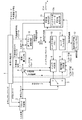
- FIG. 1 a coding control unit 1, a block division unit 2, a changeover switch 3, an intra prediction unit 4, a motion compensation prediction unit 5, a subtraction unit 6, and a transform / quantization unit 7, which are components of the moving image coding apparatus.
- the inverse quantization / inverse transform unit 8, the adder unit 9, the loop filter unit 11 and the variable length coding unit 13 each have dedicated hardware (for example, a semiconductor integrated circuit on which a CPU is mounted, or a one-chip microcomputer)
- a program describing the processing contents of the prediction unit 5, subtraction unit 6, transformation / quantization unit 7, inverse quantization / inverse transformation unit 8, addition unit 9, loop filter unit 11, and variable length coding unit 13 Computer Stored in the memory, CPU of the computer may execute a program stored in the memory.
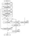
- FIG. 3 is a flowchart showing the processing contents of the moving picture coding apparatus
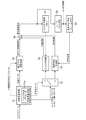
- a variable length decoding unit 51, a changeover switch 52, an intra prediction unit 53, a motion compensation prediction unit 54, an inverse quantization / inverse transformation unit 55, an addition unit 56, and a loop filter unit which are components of the moving image decoding apparatus.
- 58 is assumed to be configured by dedicated hardware (for example, a semiconductor integrated circuit on which a CPU is mounted, or a one-chip microcomputer), but the moving image decoding apparatus is configured by a computer.
- a program describing the processing contents of the variable length decoding unit 51, the changeover switch 52, the intra prediction unit 53, the motion compensation prediction unit 54, the inverse quantization / inverse transformation unit 55, the addition unit 56, and the loop filter unit 58. May be stored in the memory of the computer, and the CPU of the computer may execute the program stored in the memory.
- FIG. 4 is a flowchart showing the processing contents of the video decoding apparatus according to Embodiment 1 of the present invention.
- the encoding control unit 1 determines the maximum size of an encoding block that is a processing unit when intra prediction processing (intraframe prediction processing) or motion compensation prediction processing (interframe prediction processing) is performed, The upper limit number of layers when the coding block of the maximum size is divided hierarchically is determined (step ST1 in FIG. 3).
- a method of determining the maximum size of the encoded block for example, a method of determining a size corresponding to the resolution of the input image for all the pictures can be considered.
- the difference in complexity of local motion of the input image is quantified as a parameter, and the maximum size is determined to be a small value for pictures with intense motion, and the maximum size is determined to be a large value for pictures with little motion. Etc. are considered.
- the upper limit of the number of hierarchies is set so that, for example, the more the input image moves, the deeper the number of hierarchies, so that finer motion can be detected, and the less the input image moves, the lower the number of hierarchies. A way to do this is conceivable.
- the encoding control unit 1 includes each encoding block divided hierarchically from one or more available encoding modes (M types of intra encoding modes and N types of inter encoding modes). Is selected (step ST2). Since the encoding mode selection method by the encoding control unit 1 is a known technique, detailed description thereof is omitted. For example, encoding processing is performed on the encoding block using any available encoding mode. Then, there is a method of verifying the encoding efficiency and selecting an encoding mode having the highest encoding efficiency among a plurality of available encoding modes.
- the encoding control unit 1 determines a quantization parameter and a transform block size that are used when the difference image is compressed for each encoding block, and an intra that is used when the prediction process is performed. A prediction parameter or an inter prediction parameter is determined.
- the encoding control unit 1 outputs the prediction error encoding parameter including the quantization parameter and the transform block size to the transform / quantization unit 7, the inverse quantization / inverse transform unit 8, and the variable length coding unit 13. Further, the prediction error coding parameter is output to the intra prediction unit 4 as necessary.
- FIG. 5 is an explanatory diagram showing a state in which a coding block of the maximum size is hierarchically divided into a plurality of coding blocks.
- the coding block of the maximum size is the coding block B 0 of the 0th layer, and has a size of (L 0 , M 0 ) as a luminance component.
- the encoding block B n is obtained by performing hierarchical division to a predetermined depth determined separately in a quadtree structure with the encoding block B 0 having the maximum size as a starting point. Yes.
- the coding block B n is an image area of size (L n , M n ).
- the size of the encoded block B n is defined as the size of the luminance component of the encoded block B n (L n, M n ).
- the encoding mode m (B n ) may be configured to use an individual mode for each color component, but hereinafter, unless otherwise specified, YUV The description will be made on the assumption that it indicates the coding mode for the luminance component of the coding block of the signal 4: 2: 0 format.
- the coding mode m (B n ) includes one or more intra coding modes (collectively “INTRA”), one or more inter coding modes (collectively “INTER”), As described above, the encoding control unit 1 selects an encoding mode having the highest encoding efficiency for the encoding block B n from all the encoding modes available for the picture or a subset thereof. .
- the coding block B n is further divided into one or more prediction processing units (partitions).
- the partition belonging to the coding block B n is denoted as P i n (i: the partition number in the nth layer). How the partition P i n belonging to the coding block B n is divided is included as information in the coding mode m (B n ). All partitions P i n are subjected to prediction processing according to the coding mode m (B n ), but individual prediction parameters can be selected for each partition P i n .
- the encoding control unit 1 generates a block division state as shown in FIG. 6 for the encoding block of the maximum size, and specifies the encoding block Bn .
- 6A shows the distribution of the partitions after the division
- FIG. 6B shows a situation where the encoding mode m (B n ) is assigned to the partition after the hierarchy division in the quadtree graph. Is shown.
- nodes surrounded by squares indicate nodes (encoded blocks B n ) to which the encoding mode m (B n ) is assigned.
- the encoding control unit 1 selects the optimal coding mode m (B n) for the partition P i n in each of the coding blocks B n, the encoding mode m (B n) is If it is the intra coding mode (step ST3), the partition P i n of the coding block B n divided by the block dividing unit 2 is output to the intra prediction unit 4. On the other hand, if the coding mode m (B n ) is the inter coding mode (step ST 3), the partition P i n of the coding block B n divided by the block dividing unit 2 is output to the motion compensation prediction unit 5. To do.
- the intra prediction unit 4 When the intra prediction unit 4 receives the partition P i n of the coding block B n from the changeover switch 3, the intra prediction unit 4 uses the coded image signal in the frame as the intra prediction parameter output from the coding control unit 1. Based on this, intra-prediction processing for the partition P i n of the coding block B n is performed to generate an intra prediction image P i n (step ST4). However, the intra prediction unit 4, after generating the intra prediction image P i n in the above, from among one or more filters prepared in advance, depending on the state of various parameters relating to the encoding of the filter processing target block select a filter, using the filter, carrying out the filtering processing for the intra prediction image P i n.
- Intra prediction unit 4 when carrying out filter processing of the intra prediction image P i n, but outputs the intra prediction image P i n after filtering the subtraction unit 6 and the addition section 9, even in the video decoding apparatus of FIG. 2 to be able to generate the same intra prediction image P i n, and outputs the intra prediction parameters in variable length coding unit 13.
- the outline of the processing content of the intra prediction unit 4 is as described above, but the detailed processing content will be described later.
- the motion compensation prediction unit 5 When the motion compensation prediction unit 5 receives the partition P i n of the coding block B n from the changeover switch 3, the motion compensation prediction unit 5 uses the reference image of one or more frames stored in the motion compensation prediction frame memory 12 to use the coding control unit. based on the inter prediction parameter output from the 1, it generates an inter prediction image P i n by performing motion compensation prediction processing on partition P i n in the coded blocks B n (step ST5).
- generates a prediction image by implementing a motion compensation prediction process is a well-known technique, detailed description is abbreviate
- the subtraction unit 6 encodes the encoded block B n divided by the block division unit 2.
- a difference image is generated by subtracting a prediction image (intra prediction image P i n , inter prediction image P i n ) generated by the intra prediction unit 4 or the motion compensated prediction unit 5 from the partition P i n of a prediction error signal e i n representing a difference image is output to the transform and quantization unit 7 (step ST6).
- the transform / quantization unit 7 When the transform / quantization unit 7 receives the prediction error signal e i n indicating the difference image from the subtraction unit 6, the transform / quantization unit 7 performs the transform block size unit included in the prediction error coding parameter output from the coding control unit 1.
- the difference image conversion process for example, DCT (Discrete Cosine Transform) or orthogonal conversion process such as KL conversion in which a base design is made in advance for a specific learning sequence
- the prediction error encoding is performed.
- the quantization coefficient included in the parameter is used to quantize the transform coefficient of the difference image, so that the quantized transform coefficient is converted into the compressed data of the difference image and the inverse quantization / inverse transform unit 8 and the variable length It outputs to the encoding part 13 (step ST7).
- the inverse quantization / inverse transform unit 8 uses the quantization parameter included in the prediction error coding parameter output from the coding control unit 1. Then, the compressed data of the difference image is inversely quantized, and inverse transform processing of the compressed data of inverse quantization (for example, inverse DCT (inverse discrete cosine transform) is performed in the unit of transform block size included in the prediction error encoding parameter.
- inverse transform processing of the compressed data of inverse quantization for example, inverse DCT (inverse discrete cosine transform) is performed in the unit of transform block size included in the prediction error encoding parameter.
- the adder 9 Upon receiving the local decoded prediction error signal e i n hat from the inverse quantization / inverse transform unit 8, the adder 9 receives the local decoded prediction error signal e i n hat and the intra prediction unit 4 or the motion compensation prediction unit 5. By adding a prediction signal indicating the generated prediction image (intra prediction image P i n , inter prediction image P i n ), a local decoded partition image P i n hat or a local decoded encoded block image as a collection thereof is used. A local decoded image is generated (step ST9). When generating the locally decoded image, the adding unit 9 stores the locally decoded image signal indicating the locally decoded image in the intra prediction memory 10 and outputs the locally decoded image signal to the loop filter unit 11.
- steps ST3 to ST9 are repeatedly performed until the processes for all the encoded blocks Bn divided hierarchically are completed, and when the processes for all the encoded blocks Bn are completed, the process proceeds to the process of step ST12. (Steps ST10 and ST11).
- the variable length encoding unit 13 includes the compressed data output from the transform / quantization unit 7, the encoding mode output from the encoding control unit 1 (including information indicating the division state of the encoded block), and a prediction error.
- the encoding parameter and the intra prediction parameter output from the intra prediction unit 4 or the inter prediction parameter output from the motion compensation prediction unit 5 are entropy encoded.
- the variable length encoding unit 13 multiplexes the compressed data, the encoding mode, the prediction error encoding parameter, and the intra prediction parameter / inter prediction parameter encoded data, which are the encoding results of entropy encoding, to generate a bitstream. (Step ST12).
- the loop filter unit 11 compensates for the encoding distortion included in the locally decoded image signal, and the locally decoded image indicated by the locally decoded image signal after the encoding distortion compensation Is stored in the motion compensated prediction frame memory 12 as a reference image (step ST13).
- the filtering process by the loop filter unit 11 may be performed on the maximum encoded block of the locally decoded image signal output from the adder 9 or on an individual encoded block basis, or on a unit of a plurality of maximum encoded blocks. Or after one local decoded image signal for one picture has been output.
- FIG. 7 is an explanatory diagram showing an example of intra prediction parameters (intra prediction modes) that can be selected in each partition P i n in the coding block B n .
- intra prediction modes intra prediction parameters
- the intra prediction mode and the prediction direction vector indicated by the intra prediction mode are represented, and the relative angle between the prediction direction vectors decreases as the number of selectable intra prediction modes increases. is doing.
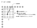
- the intra prediction unit 4 performs an intra prediction process for the partition P i n based on an intra prediction parameter for the partition P i n and a selection parameter of a filter used for generating the intra predicted image P i n .
- intra prediction parameters intra prediction mode
- P i n described intra process of generating an intra prediction signal of the luminance signal.
- the number of pixels used for prediction may be more or less than the pixels shown in FIG.
- pixels for one adjacent row or one column are used for prediction, but two or two or more pixels may be used for prediction.
- the index value of the intra prediction mode for the partition P i n 2 (average value prediction)
- the average value of the adjacent pixels of the upper partition and the adjacent pixels of the left partition is used as the predicted value of the pixels in the partition P i n .
- a prediction image is generated.
- the position of the reference pixel used for prediction is the intersection of A and the adjacent pixel shown below.
- the integer pixel When the reference pixel is at the integer pixel position, the integer pixel is set as the prediction value of the prediction target pixel. On the other hand, when the reference pixel is not located at the integer pixel position, an interpolation pixel generated from the integer pixel adjacent to the reference pixel is set as the predicted value. In the example of FIG. 8, since the reference pixel is not located at the integer pixel position, the prediction value is calculated by interpolating from two pixels adjacent to the reference pixel. However, the predicted value is not limited to two adjacent pixels, and an interpolation pixel may be generated from two or more adjacent pixels as the predicted value.
- a filter to be used is selected from at least one or more filters prepared in advance by a method described later, and filter processing is performed on each pixel of the intermediate predicted image according to the following equation (1).
- s (p n ) represents the luminance value of each reference pixel, and s hat (p 0 ) represents the luminance value after filtering in the pixel to be filtered p 0 .
- the filter coefficients may be configured that there is no offset coefficient a N.
- N is an arbitrary number of reference pixels.
- the filtering process When performing the filtering process, as the size of the partition P i n (l i n ⁇ m i n) is large, non-straight edges such as is likely to exist in the input image, the predicted direction of the intermediate prediction image Since the deviation is likely to occur, it is preferable to smooth the intermediate predicted image. Furthermore, the larger the quantized value of the prediction error, quantization distortion generated in the decoded image is increased, because the prediction accuracy of the intermediate predicted image generated from encoded pixels adjacent to the partition P i n is lower it is preferable to prepare a predicted image such smoothed to roughly represent the partition P i n.
- the misalignment of the edge or the like between the intermediate predicted image and the input image Since it is likely to occur, it is better to smooth the prediction image so as to suppress a sudden increase in prediction error when a deviation occurs.
- the reference pixels are appropriately arranged according to the prediction direction of the intermediate prediction image, and the pattern such as the edge of the intermediate prediction image is unnaturally distorted. It is necessary not to.
- the filter selection process is configured to select a filter in consideration of the following four parameters (1) to (4).
- the filter strength and the reference pixel arrangement in consideration of the prediction direction of the intra prediction mode so that the filter with stronger smoothing strength is used as the distance from the encoded pixel group used when generating an intermediate prediction image increases.
- adaptive selection of a filter according to the above parameters is realized by associating an appropriate filter from a group of filters prepared in advance with each of the above parameter combinations.
- the number of types of filter strengths is not limited as long as it is two or more, and the weakest filter may be defined as processing equivalent to no filter processing as an expression of filter strength. Therefore, the filter process may be configured such that only a specific pixel in the intermediate prediction image is filtered and the other pixels are the weakest filter process, that is, no filter process is performed. In the above description, it is assumed that a necessary number of filters are prepared in advance. However, the filter is selected so that the filter is calculated according to the value of the filter selection parameter. It may be defined and used as a function.
- the configuration is shown in which the filter is selected in consideration of the four parameters (1) to (4), but at least the four parameters (1) to (4) are selected.
- the filter may be selected in consideration of one or more parameters.
- the distance from the pixel used for prediction of each pixel to be filtered according to the prediction direction of the intra prediction mode (example in FIG. 8).
- a configuration in which a stronger filter is selected as a distance from a “reference pixel” adjacent to the upper end of the block increases.
- the four parameters (1) to (4) are parameters already known on the moving image decoding apparatus side, no additional information to be encoded is generated by performing the above filter processing.
- Intra prediction parameters used to generate the intra prediction image P i n outputs to the variable length coding unit 13 for multiplexing the bitstream.
- the intra-prediction of the color difference signal may be configured so that the filtering process described above is performed in the same manner as the luminance signal, or may not be performed.
- variable length decoding unit 51 receives the bit stream output from the image encoding device in FIG. 1, the variable length decoding unit 51 performs a variable length decoding process on the bit stream and performs a sequence unit or a picture composed of one or more frames.
- the frame size information is decoded in units (step ST21 in FIG. 4).
- the variable length decoding unit 51 is a unit of processing when intra prediction processing (intraframe prediction processing) or motion compensation prediction processing (interframe prediction processing) is performed in the same procedure as the coding control unit 1 in FIG. Is determined, and the upper limit number of layers when the maximum size encoded block is hierarchically divided is determined (step ST22).
- the maximum size of the encoded block is determined according to the resolution of the input image, the maximum size of the encoded block is determined based on the previously decoded frame size information. .
- the information decoded from the bit stream is referred to.
- variable The long decoding unit 51 decodes the encoding mode m (B 0 ) of the maximum size encoding block B 0 multiplexed in the bitstream, and each encoding block B n divided hierarchically. Is specified (step ST23).
- the variable length decoding unit 51 identifies each coding block B n
- the variable length decoding unit 51 decodes the coding mode m (B n ) of the coding block B n and belongs to the coding mode m (B n ).
- variable length decoding unit 51 based on the information of the partition P i n, identifies the partition P i n that belong to coded blocks B n.
- the variable length decoding unit 51 compresses the compressed data, the coding mode, the prediction error coding parameter, the intra prediction parameter / inter prediction for each partition P i n.
- the parameter is decoded (step ST24).
- the intra prediction parameter is decoded for each partition P i n belonging to the coding block.
- the coding mode m (B n ) assigned to the coding block B n is the inter coding mode
- the inter prediction parameter is decoded for each partition P i n belonging to the coding block.
- the partition serving as the prediction processing unit is further divided into one or a plurality of partitions serving as the transform processing unit based on the transform block size information included in the prediction error encoding parameter, and compressed data (for each partition serving as the transform processing unit ( (Transform coefficient after transform / quantization) is decoded.
- the changeover switch 52 is the variable length decoding unit (step ST25).
- the intra prediction parameter output from 51 is output to the intra prediction unit 53.
- the coding mode m (B n ) of the partition P i n is the inter coding mode (step ST25)
- the inter prediction parameter output from the variable length decoding unit 51 is output to the motion compensation prediction unit 54.
- the intra prediction unit 53 When receiving the intra prediction parameter from the changeover switch 52, the intra prediction unit 53 uses the decoded image signal in the frame and encodes it based on the intra prediction parameter, as in the case of the intra prediction unit 4 in FIG.
- An intra-prediction image P i n is generated by performing intra-frame prediction processing on the partition P i n of the block B n (step ST26).
- the intra prediction unit 53 when generating an intra prediction image P i n, from among one or more filters prepared in advance by the intra prediction unit 4 and the same procedure of FIG.
- the decoding of the filter processing target block select a filter according to the state of various parameters relating to, using the filter, and out the filter processing for the intra prediction image P i n, final intra intra prediction image P i n after filtering It is a predicted image.
- the filters are calculated according to the parameter states used by the intra prediction unit 4 in FIG. 1 for filter selection.
- the intra prediction unit 53 similarly sets the filter so that the filter is calculated according to the state of various parameters related to the decoding of the filter processing target block. You may comprise so that it may define as a function of.
- the motion compensation prediction unit 54 uses one or more reference images stored in the motion compensation prediction frame memory 59, and based on the inter prediction parameter, encodes a coding block.
- An inter-predicted image P i n is generated by performing motion compensation prediction processing for the partition P i n of B n (step ST27).
- the inverse quantization / inverse transform unit 55 uses the quantization parameter included in the prediction error coding parameter output from the variable length decoding unit 51, and relates to the coding block output from the variable length decoding unit 51.
- the compressed data is inversely quantized, and the inverse quantization processing (for example, inverse DCT (inverse discrete cosine transform) or inverse KL transform) is performed on the basis of the transform block size included in the prediction error coding parameter.
- the inverse quantization processing for example, inverse DCT (inverse discrete cosine transform) or inverse KL transform
- the compressed data after the inverse transformation process is output to the adding unit 56 as a decoded prediction error signal (a signal indicating a difference image before compression) (step ST28).
- the adding unit 56 Upon receiving the decoded prediction error signal from the inverse quantization / inverse transform unit 55, the adding unit 56 adds the decoded prediction error signal and a prediction signal indicating the prediction image generated by the intra prediction unit 53 or the motion compensated prediction unit 54 Thus, a decoded image is generated, and a decoded image signal indicating the decoded image is stored in the intra prediction memory 57, and the decoded image signal is output to the loop filter unit 58 (step ST29).
- steps ST23 to ST29 are repeatedly performed until the processes for all the hierarchically divided coding blocks Bn are completed (step ST30).
- the loop filter unit 58 compensates for the encoding distortion included in the decoded image signal, and uses the decoded image indicated by the decoded image signal after the encoding distortion compensation as a reference image. It stores in the motion compensation prediction frame memory 59 (step ST31).
- the filtering process by the loop filter unit 58 may be performed in units of maximum encoded blocks or individual encoded blocks of the decoded image signal output from the adder 56, or a decoded image signal corresponding to a macroblock for one screen. May be performed for one screen at a time after is output.
- the intra prediction unit 4 of the video encoding device performs intra-frame prediction processing using an intra-frame encoded image signal, thereby allowing intra-frame prediction processing.
- a filter is selected from one or more filters prepared in advance according to the state of various parameters related to the encoding of the filter processing target block, and the filter is used to generate the prediction image. Since the configuration is such that the filtering process is performed, an effect of reducing the prediction error that occurs locally and improving the image quality is achieved.
- a quantum intra prediction unit 4 is included (1) the size of the partition P i n (l i n ⁇ m i n), (2) the prediction error encoding parameters (3) the distance between the encoded pixel group used when generating the intermediate prediction image and the pixel to be filtered, and (4) the index value of the intra prediction mode when generating the intermediate prediction image, at least Since the filter is selected in consideration of one or more parameters, the intermediate prediction image having a high correlation with the encoding target image is between the edge direction and the prediction direction of the encoding target image. An effect of suppressing a local prediction error that occurs when there is a slight shift or a slight distortion at the edge is obtained, and the effect of improving the prediction efficiency is achieved.
- the intra prediction unit 53 of the video decoding device prepares in advance when generating an intra predicted image by performing an intra frame prediction process using a decoded image signal in a frame. Since the filter is selected according to the state of various parameters related to the decoding of the filter processing target block from the one or more filters that are being processed, and the filter process is performed on the prediction image using the filter. In addition, it is possible to reduce the locally generated prediction error and to generate the same intra-predicted image as the intra-predicted image generated on the video encoding device side on the video decoding device side.
- a quantum intra prediction unit 53 is included (1) the size of the partition P i n (l i n ⁇ m i n), (2) the prediction error encoding parameters (3) the distance between the encoded pixel group used when generating the intermediate prediction image and the pixel to be filtered, and (4) the index value of the intra prediction mode when generating the intermediate prediction image, at least Since the filter is selected in consideration of one or more parameters, the intermediate prediction image having a high correlation with the encoding target image is between the edge direction and the prediction direction of the encoding target image.
- Embodiment 2 when the intra prediction unit 4 generates an intra predicted image by performing an intra frame prediction process using an encoded image signal in a frame, one or more prepared in advance.
- the filter is selected according to the state of various parameters related to the encoding of the block to be filtered, and the filter processing is performed on the prediction image using the filter. Designing a Wiener filter that minimizes the sum of square errors between a block and a predicted image, and using the Wiener filter rather than using a filter selected from one or more filters prepared in advance However, if the degree of reduction of the prediction error is high, the Wiener filter is used instead of the selected filter to Filtering of the may be performed.
- the processing contents will be specifically described below.
- the intra prediction units 4 and 53 select a filter from one or more prepared filters according to the state of various parameters related to the encoding of the filter processing target block. ing.
- a filter in consideration of the four parameters (1) to (4), it is possible to select an appropriate filter from the selection candidates, but there is an optimum filter other than the selection candidates. In this case, “optimal filter processing” cannot be performed.
- an optimal filter is designed and filtered on the moving picture encoding device side for each picture, and the filter coefficients of the filter are encoded. The filter processing using the filter is performed by decoding the filter coefficient or the like.
- the intra prediction unit 4 of the video encoding device generates an intra predicted image P i n by performing intra-frame prediction processing on the partition P i n of the encoded block B n as in the first embodiment. .
- the intra prediction unit 4 uses the same method as in the first embodiment to filter out one or more filters prepared in advance according to the state of various parameters related to the encoding of the filter processing target block. selected, it performs a filtering process to the intra prediction image P i n using this filter.
- the intra prediction unit 4 After the intra prediction parameters have been determined for all the coding blocks Bn in the picture, the intra prediction unit 4 performs an intra-region for each region (region having the same filter index) in which the same filter is used in the picture. Design a Wiener filter that minimizes the sum of square errors between the input image and the intra-predicted image (mean square error in the target region).
- the Wiener filter uses the autocorrelation matrix R s ′ s ′ of the intermediate predicted image signal s ′ and the cross-correlation matrix R ss ′ of the input image signal s and the intermediate predicted image signal s ′ to filter coefficients from the following equation (4). w can be obtained.
- the sizes of the matrices R s ′s ′ and R ss ′ correspond to the number of filter taps to be obtained.
- the intra prediction unit 4 sets the square error sum in the filter design target area when the filter process is performed using the Wiener filter to D1, and information related to the Wiener filter (for example, filter The code amount when the coefficient is encoded is R1, and the square error sum in the filter design target area when the filter processing is performed using the filter selected by the same method as in the first embodiment is D2. Then, it is confirmed whether or not the following formula (5) is established. D1 + ⁇ ⁇ R1 ⁇ D2 (5) Where ⁇ is a constant.
- the intra prediction unit 4 performs the filter process using the Wiener filter instead of the filter selected by the same method as in the first embodiment.
- the filter process is performed using the filter selected by the same method as in the first embodiment.
- the evaluation is performed using the square error sums D1 and D2, but the present invention is not limited to this. Instead of the square error sums D1 and D2, other prediction distortions such as the sum of absolute values of errors are used. You may make it evaluate using the scale to represent.
- the filter coefficient of the Wiener filter and filter update information indicating which index filter is replaced with the Wiener filter are required. Specifically, when the number of filters that can be selected by the filter processing using the filter selection parameter is L and an index of 0 to L-1 is assigned to each filter, the Wiener filter designed for each index is used. It is necessary to encode a value of “1” when using the filter update information and a value of “0” when using a filter prepared in advance as filter update information.
- the variable length encoding unit 13 performs variable length encoding on the filter update information output from the intra prediction unit 4, and multiplexes the encoded data of the filter update information into a bit stream.
- a Wiener filter that minimizes the mean square error between the input image and the predicted image in the area has been shown.
- a Wiener filter that minimizes the mean square error between the input image and the predicted image in the area may be designed for each area where the same filter is used. The filter design is performed only when a specific picture is designed or when a specific condition is met (for example, a scene change detection function is added and a scene change is detected). You may do it.
- the variable length decoding unit 51 of the video decoding device performs variable length decoding of the filter update information from the encoded data multiplexed in the bit stream.
- the intra prediction unit 53 generates an intra-predicted image P i n by performing intra-frame prediction processing on the partition P i n of the encoded block B n as in the first embodiment.
- the intra prediction unit 53 receives the filter update information from the variable length decoding unit 51, the intra prediction unit 53 refers to the filter update information and confirms whether there is an update in the filter of the corresponding index.
- the intra prediction unit 53 reads the filter coefficient of the Wiener filter included in the filter update information when the filter of a certain region is replaced with the Wiener filter, and the Wiener filter identify, using the Wiener filter performs a filtering of the intra prediction image P i n.
- the intra prediction unit 53 reads the filter coefficient of the Wiener filter included in the filter update information when the filter of a certain region is replaced with the Wiener filter, and the Wiener filter identify, using the Wiener filter performs a filtering of the intra prediction image P i n.
- the areas not replaced by Wiener filter select the filter in the same manner as in the first embodiment, by using the filter, carrying out the filtering of the intra prediction image P i n.
- a Wiener filter that minimizes the sum of square errors between a block to be encoded and a predicted image is designed, and one or more filters prepared in advance are used. If the degree of reduction in prediction error is higher when using the Wiener filter than using the filter selected from among them, using the Wiener filter instead of the selected filter, the predicted image Since the filter processing is performed, the prediction error occurring locally can be reduced more than in the first embodiment.
- the intra prediction unit uses the encoded image signal in the frame
- a filter is selected from among one or more filters prepared in advance according to the state of various parameters related to the encoding of the filter processing target block, Since the filter is used to perform the filtering process on the predicted image and the predicted image after the filter process is output to the difference image generating unit, the moving image encoding apparatus that encodes the moving image with high efficiency And a moving picture coding method, a moving picture decoding apparatus that decodes a moving picture coded with high efficiency, a moving picture decoding method, and the like.
- Encoding control unit encoding control unit
- Block division unit block division unit
- Changeover switch Intra prediction unit, motion compensation prediction unit
- Intra prediction unit Intra prediction unit
- Motion compensation prediction. Part motion compensation prediction means
- 6 subtraction part difference image generation means
- 7 transformation / quantization part image compression means
- 8 inverse quantization / inverse transformation part 9 addition part, 10 intra prediction memory, 11 Loop filter unit, 12 motion compensated prediction frame memory, 13 variable length coding unit (variable length coding unit), 51 variable length decoding unit (variable length decoding unit), 52 changeover switch (intra prediction unit, motion compensation prediction unit)
- Intra prediction unit Intra prediction unit
- Motion compensation prediction unit motion compensation prediction unit
- Inverse quantization / inverse transform unit difference image generator
- 56 adder unit decoded image generating means
- 57 intra prediction memory 58 a loop filter unit
- 59 motion-compensated prediction frame memory motion-compensated prediction frame memory.
Landscapes
- Engineering & Computer Science (AREA)
- Multimedia (AREA)
- Signal Processing (AREA)
- Compression Or Coding Systems Of Tv Signals (AREA)
Abstract
Priority Applications (27)
| Application Number | Priority Date | Filing Date | Title |
|---|---|---|---|
| MX2013003696A MX2013003696A (es) | 2010-09-30 | 2011-07-21 | Dispositivo de codificacion de imagen en movimiento, dispositivo de decodificacion de imagen en movimiento, metodo de codificacion de imagen en movimiento y metodo de decodificacion de imagen en movimiento. |
| KR1020147020864A KR101563835B1 (ko) | 2010-09-30 | 2011-07-21 | 화상 복호 장치, 화상 복호 방법, 화상 부호화 장치 및 화상 부호화 방법 |
| EP11828289.6A EP2624563A4 (fr) | 2010-09-30 | 2011-07-21 | Appareil de codage de vidéo animée, appareil de décodage de vidéo animée, procédé de codage de vidéo animée et procédé de décodage de vidéo animée |
| CN201180047243.5A CN103141106B (zh) | 2010-09-30 | 2011-07-21 | 运动图像编码装置、运动图像解码装置、运动图像编码方法以及运动图像解码方法 |
| KR1020157035466A KR101669388B1 (ko) | 2010-09-30 | 2011-07-21 | 부호화 데이터가 기록된 기록 매체 |
| CA2812201A CA2812201C (fr) | 2010-09-30 | 2011-07-21 | Appareil de codage de video animee, appareil de decodage de video animee, procede de codage de video animee et procede de decodage de video animee |
| RU2013119934/08A RU2544799C2 (ru) | 2010-09-30 | 2011-07-21 | Устройство кодирования движущихся изображений, устройство декодирования движущихся изображений, способ кодирования движущихся изображений и способ декодирования движущихся изображений |
| BR112013006501-0A BR112013006501B1 (pt) | 2010-09-30 | 2011-07-21 | Dispositivo de decodificação de imagem, e, dispositivo de codificação de imagem |
| KR1020147020862A KR101563834B1 (ko) | 2010-09-30 | 2011-07-21 | 화상 복호 장치, 화상 복호 방법, 화상 부호화 장치 및 화상 부호화 방법 |
| EP20150124.4A EP3661213A1 (fr) | 2010-09-30 | 2011-07-21 | Dispositif de codage d'images en mouvement, dispositif de décodage d'images en mouvement, procédé de codage d'images en mouvement et procédé de décodage d'images en mouvement |
| JP2012536150A JP5503747B2 (ja) | 2010-09-30 | 2011-07-21 | 画像符号化装置、画像復号装置、画像符号化方法及び画像復号方法 |
| MX2014009677A MX338462B (es) | 2010-09-30 | 2011-07-21 | Dispositivo de codificacion de imagen en movimiento, dispositivo de decodificacion de imagen en movimiento, metodo de codificacion de imagen en movimiento y metodo de decodificacion de imagen en movimiento. |
| KR1020137010924A KR101580021B1 (ko) | 2010-09-30 | 2011-07-21 | 화상 복호 장치, 화상 부호화 장치, 화상 부호화 방법 및 화상 복호 방법 |
| KR1020147020850A KR101563833B1 (ko) | 2010-09-30 | 2011-07-21 | 화상 복호 장치, 화상 복호 방법, 화상 부호화 장치 및 화상 부호화 방법 |
| KR1020147020866A KR101578318B1 (ko) | 2010-09-30 | 2011-07-21 | 화상 복호 장치, 화상 복호 방법, 화상 부호화 장치 및 화상 부호화 방법 |
| US13/822,887 US10291939B2 (en) | 2010-09-30 | 2011-07-21 | Moving image encoding device, moving image decoding device, moving image coding method, and moving image decoding method |
| SG2013021928A SG189076A1 (en) | 2010-09-30 | 2011-07-21 | Moving image encoding device, moving image decoding device, moving image coding method, and moving image decoding method |
| TW105123725A TWI603612B (zh) | 2010-09-30 | 2011-09-14 | 畫像編碼裝置、畫像解碼裝置、畫像編碼方法、畫像解碼方法及資料結構 |
| TW100132970A TWI472229B (zh) | 2010-09-30 | 2011-09-14 | 動畫像編碼裝置、動畫像解碼裝置、動畫像編碼方法及動畫像解碼方法 |
| TW103145688A TWI566588B (zh) | 2010-09-30 | 2011-09-14 | 畫像編碼裝置、畫像解碼裝置、畫像編碼方法、畫像解碼方法及資料結構 |
| TW105123731A TWI606720B (zh) | 2010-09-30 | 2011-09-14 | 畫像編碼裝置、畫像解碼裝置、畫像編碼方法、畫像解碼方法及記錄媒體 |
| TW105123734A TWI606721B (zh) | 2010-09-30 | 2011-09-14 | 畫像編碼裝置、畫像解碼裝置、畫像編碼方法、畫像解碼方法及記錄媒體 |
| HK13109293.0A HK1182244A1 (zh) | 2010-09-30 | 2013-08-08 | 運動圖像編碼裝置、運動圖像解碼裝置、運動圖像編碼方法以及運動圖像解碼方法 |
| US14/634,550 US10244233B2 (en) | 2010-09-30 | 2015-02-27 | Moving image encoding device, moving image decoding device, moving image coding method, and moving image decoding method |
| US14/634,485 US10237551B2 (en) | 2010-09-30 | 2015-02-27 | Moving image encoding device, moving image decoding device, moving image coding method, and moving image decoding method |
| US14/634,453 US10237550B2 (en) | 2010-09-30 | 2015-02-27 | Moving image encoding device, moving image decoding device, moving image coding method, and moving image decoding method |
| US14/634,561 US10244264B2 (en) | 2010-09-30 | 2015-02-27 | Moving image encoding device, moving image decoding device, moving image coding method, and moving image decoding method |
Applications Claiming Priority (2)
| Application Number | Priority Date | Filing Date | Title |
|---|---|---|---|
| JP2010-221471 | 2010-09-30 | ||
| JP2010221471 | 2010-09-30 |
Related Child Applications (5)
| Application Number | Title | Priority Date | Filing Date |
|---|---|---|---|
| US13/822,887 A-371-Of-International US10291939B2 (en) | 2010-09-30 | 2011-07-21 | Moving image encoding device, moving image decoding device, moving image coding method, and moving image decoding method |
| US14/634,485 Division US10237551B2 (en) | 2010-09-30 | 2015-02-27 | Moving image encoding device, moving image decoding device, moving image coding method, and moving image decoding method |
| US14/634,561 Division US10244264B2 (en) | 2010-09-30 | 2015-02-27 | Moving image encoding device, moving image decoding device, moving image coding method, and moving image decoding method |
| US14/634,453 Division US10237550B2 (en) | 2010-09-30 | 2015-02-27 | Moving image encoding device, moving image decoding device, moving image coding method, and moving image decoding method |
| US14/634,550 Division US10244233B2 (en) | 2010-09-30 | 2015-02-27 | Moving image encoding device, moving image decoding device, moving image coding method, and moving image decoding method |
Publications (1)
| Publication Number | Publication Date |
|---|---|
| WO2012042720A1 true WO2012042720A1 (fr) | 2012-04-05 |
Family
ID=45892218
Family Applications (1)
| Application Number | Title | Priority Date | Filing Date |
|---|---|---|---|
| PCT/JP2011/004122 WO2012042720A1 (fr) | 2010-09-30 | 2011-07-21 | Appareil de codage de vidéo animée, appareil de décodage de vidéo animée, procédé de codage de vidéo animée et procédé de décodage de vidéo animée |
Country Status (13)
| Country | Link |
|---|---|
| US (5) | US10291939B2 (fr) |
| EP (2) | EP3661213A1 (fr) |
| JP (5) | JP5503747B2 (fr) |
| KR (6) | KR101563834B1 (fr) |
| CN (5) | CN105516722B (fr) |
| BR (1) | BR112013006501B1 (fr) |
| CA (5) | CA3000366C (fr) |
| HK (3) | HK1219594A1 (fr) |
| MX (2) | MX338462B (fr) |
| RU (5) | RU2608674C2 (fr) |
| SG (5) | SG10201911999WA (fr) |
| TW (5) | TWI566588B (fr) |
| WO (1) | WO2012042720A1 (fr) |
Cited By (5)
| Publication number | Priority date | Publication date | Assignee | Title |
|---|---|---|---|---|
| JP2013012895A (ja) * | 2011-06-29 | 2013-01-17 | Nippon Telegr & Teleph Corp <Ntt> | 画像符号化装置、画像復号装置、画像符号化方法、画像復号方法、画像符号化プログラム及び画像復号プログラム |
| US9299133B2 (en) | 2011-01-12 | 2016-03-29 | Mitsubishi Electric Corporation | Image encoding device, image decoding device, image encoding method, and image decoding method for generating a prediction image |
| WO2016129185A1 (fr) * | 2015-02-09 | 2016-08-18 | Kddi株式会社 | Dispositif de codage d'image animée, dispositif de décodage d'image animée, système de traitement d'image animée, procédé de codage d'image animée, procédé de décodage d'image animée, et programme |
| JP2017005506A (ja) * | 2015-06-10 | 2017-01-05 | 日本電信電話株式会社 | イントラ予測処理装置、イントラ予測処理方法、イントラ予測処理プログラム、画像符号化装置及び画像復号装置 |
| US9723316B2 (en) | 2011-06-24 | 2017-08-01 | Mitsubishi Electric Corporation | Image encoding device, image decoding device, image encoding method, image decoding method, and image prediction device |
Families Citing this family (24)
| Publication number | Priority date | Publication date | Assignee | Title |
|---|---|---|---|---|
| CN105516722B (zh) * | 2010-09-30 | 2018-12-07 | 三菱电机株式会社 | 运动图像编码装置及方法、运动图像解码装置及方法 |
| PL2744204T3 (pl) * | 2011-09-14 | 2019-03-29 | Samsung Electronics Co., Ltd. | Sposób dekodowania jednostki predykcji (pu) w oparciu o jej rozmiar |
| WO2013081085A1 (fr) * | 2011-11-28 | 2013-06-06 | Canon Kabushiki Kaisha | Appareil de codage d'images animées, procédé de commande de celui-ci et programme informatique |
| CN105981389B (zh) * | 2014-02-03 | 2019-03-01 | 三菱电机株式会社 | 图像编码装置、图像解码装置、编码流变换装置、图像编码方法以及图像解码方法 |
| JP6221820B2 (ja) * | 2014-02-25 | 2017-11-01 | 株式会社Jvcケンウッド | 符号化装置、符号化方法および符号化プログラム |
| CN111885379B (zh) * | 2015-03-23 | 2023-10-27 | Lg 电子株式会社 | 在内预测模式的基础上处理图像的方法及其装置 |
| CN105049846B (zh) * | 2015-08-14 | 2019-05-21 | 广东中星微电子有限公司 | 图像和视频编解码的方法和设备 |
| EP3340621B1 (fr) * | 2015-08-20 | 2023-01-25 | Nippon Hoso Kyokai | Dispositif d'encodage d'image, dispositif de décodage d'image, et programmes associés |
| CN105872538B (zh) * | 2016-04-18 | 2020-12-29 | 广东中星微电子有限公司 | 时域滤波方法和时域滤波装置 |
| CN114745547A (zh) * | 2016-05-27 | 2022-07-12 | 松下电器(美国)知识产权公司 | 编码装置及解码装置 |
| CN114286091A (zh) * | 2016-09-05 | 2022-04-05 | Lg电子株式会社 | 图像编码和解码方法、比特流存储介质及数据传输方法 |
| KR102471207B1 (ko) | 2016-10-04 | 2022-11-25 | 주식회사 케이티 | 비디오 신호 처리 방법 및 장치 |
| US10681354B2 (en) * | 2016-12-05 | 2020-06-09 | Lg Electronics Inc. | Image encoding/decoding method and apparatus therefor |
| CN110290384A (zh) * | 2018-03-19 | 2019-09-27 | 华为技术有限公司 | 图像滤波方法、装置及视频编解码器 |
| CN110650349B (zh) | 2018-06-26 | 2024-02-13 | 中兴通讯股份有限公司 | 一种图像编码方法、解码方法、编码器、解码器及存储介质 |
| WO2020249124A1 (fr) * | 2019-06-14 | 2020-12-17 | Beijing Bytedance Network Technology Co., Ltd. | Manipulation de limites d'unité vidéo et de limites virtuelles sur la base d'un format de couleur |
| CN117478878A (zh) | 2019-07-09 | 2024-01-30 | 北京字节跳动网络技术有限公司 | 用于自适应环路滤波的样点确定 |
| JP7291845B2 (ja) | 2019-07-11 | 2023-06-15 | 北京字節跳動網絡技術有限公司 | 適応ループフィルタリングにおけるサンプルパディング |
| WO2021008546A1 (fr) | 2019-07-15 | 2021-01-21 | Beijing Bytedance Network Technology Co., Ltd. | Accès à des échantillons dans des limites d'unité vidéo dans un filtrage de boucle adaptatif |
| CN114503594B (zh) | 2019-09-22 | 2024-04-05 | 北京字节跳动网络技术有限公司 | 自适应环路滤波中样点填充的选择性应用 |
| EP4022910A4 (fr) | 2019-09-27 | 2022-11-16 | Beijing Bytedance Network Technology Co., Ltd. | Filtrage en boucle adaptatif entre différentes unités vidéo |
| WO2021068906A1 (fr) | 2019-10-10 | 2021-04-15 | Beijing Bytedance Network Technology Co., Ltd. | Procédé de remplissage à des emplacements d'échantillons indisponibles dans un filtrage en boucle adaptatif |
| CN114424549A (zh) * | 2019-10-31 | 2022-04-29 | 株式会社索思未来 | 运动图像编码方法、编码处理方法、运动图像编码装置及编码处理装置 |
| US20220060702A1 (en) * | 2020-08-21 | 2022-02-24 | Alibaba Group Holding Limited | Systems and methods for intra prediction smoothing filter |
Citations (4)
| Publication number | Priority date | Publication date | Assignee | Title |
|---|---|---|---|---|
| JP2006229411A (ja) * | 2005-02-16 | 2006-08-31 | Matsushita Electric Ind Co Ltd | 画像復号化装置及び画像復号化方法 |
| WO2009120040A2 (fr) * | 2008-03-27 | 2009-10-01 | Lg Electronics Inc. | Procédé et appareil de codage ou décodage d'un signal vidéo |
| WO2010064675A1 (fr) * | 2008-12-03 | 2010-06-10 | ソニー株式会社 | Appareil de traitement d'image, procédé de traitement d'image et programme |
| JP2010183162A (ja) * | 2009-02-03 | 2010-08-19 | Mitsubishi Electric Corp | 動画像符号化装置 |
Family Cites Families (53)
| Publication number | Priority date | Publication date | Assignee | Title |
|---|---|---|---|---|
| US103475A (en) * | 1870-05-24 | Improvement in water-wheels | ||
| DE10158658A1 (de) | 2001-11-30 | 2003-06-12 | Bosch Gmbh Robert | Verfahren zur gerichteten Prädiktion eines Bildblockes |
| US7167522B2 (en) * | 2003-02-27 | 2007-01-23 | Texas Instruments Incorporated | Video deblocking filter |
| MXPA05011010A (es) | 2003-04-14 | 2005-12-12 | Gencell Corp | Aparato y metodo para la adicion de electrolito a celdas energeticas. |
| JP4617644B2 (ja) * | 2003-07-18 | 2011-01-26 | ソニー株式会社 | 符号化装置及び方法 |
| JP4699685B2 (ja) * | 2003-08-21 | 2011-06-15 | パナソニック株式会社 | 信号処理装置及びそれを用いた電子機器 |
| WO2005083253A1 (fr) * | 2004-02-27 | 2005-09-09 | Yamaha Hatsudoki Kabushiki Kaisha | Pièce de composant de moteur et procédé de production de celle-ci |
| KR100616164B1 (ko) * | 2004-05-12 | 2006-08-25 | 주식회사 대우일렉트로닉스 | 메디안 필터를 이용한 적응적인 영상 디인터레이스 장치및 그 방법 |
| KR100813958B1 (ko) * | 2004-06-07 | 2008-03-14 | 세종대학교산학협력단 | 동영상의 무손실 인코딩 및 디코딩 방법, 그 장치 |
| KR20070026515A (ko) * | 2004-06-14 | 2007-03-08 | 모노리스 컴퍼니 리미티드 | 동영상 부호화 방법 및 동영상 복호 방법 |
| JP2006032999A (ja) | 2004-07-12 | 2006-02-02 | Sharp Corp | 画像復号装置及び画像復号方法 |
| US7283634B2 (en) | 2004-08-31 | 2007-10-16 | Dts, Inc. | Method of mixing audio channels using correlated outputs |
| JP2006157481A (ja) * | 2004-11-30 | 2006-06-15 | Canon Inc | 画像符号化装置及びその方法 |
| JP2006254232A (ja) * | 2005-03-11 | 2006-09-21 | Toshiba Corp | 情報処理装置およびプログラム |
| WO2007003836A2 (fr) * | 2005-06-30 | 2007-01-11 | France Telecom | Procede et dispositif de codage video |
| US20090123066A1 (en) * | 2005-07-22 | 2009-05-14 | Mitsubishi Electric Corporation | Image encoding device, image decoding device, image encoding method, image decoding method, image encoding program, image decoding program, computer readable recording medium having image encoding program recorded therein, |
| WO2007055445A1 (fr) | 2005-11-11 | 2007-05-18 | Daegu Gyeongbuk Institute Of Science And Technology | Procede de previsualisation de plusieurs films ou filmets dans un appareil multimedia |
| JP5044415B2 (ja) * | 2005-11-30 | 2012-10-10 | 株式会社東芝 | 画像符号化/画像復号化方法及び画像符号化/画像復号化装置 |
| CN101502124B (zh) * | 2006-07-28 | 2011-02-23 | 株式会社东芝 | 图像编码和解码的方法以及装置 |
| TW200808067A (en) * | 2006-07-31 | 2008-02-01 | Univ Nat Cheng Kung | Prediction module |
| US9001899B2 (en) | 2006-09-15 | 2015-04-07 | Freescale Semiconductor, Inc. | Video information processing system with selective chroma deblock filtering |
| JP2010507335A (ja) | 2006-10-18 | 2010-03-04 | トムソン ライセンシング | 予測データ精緻化を使用してビデオを符号化する方法及び装置 |
| JP4571955B2 (ja) * | 2007-02-07 | 2010-10-27 | 日本電信電話株式会社 | 適応デブロッキング処理方法,装置および適応デブロッキング処理プログラム並びにコンピュータ読み取り可能な記録媒体 |
| US8422803B2 (en) * | 2007-06-28 | 2013-04-16 | Mitsubishi Electric Corporation | Image encoding device, image decoding device, image encoding method and image decoding method |
| US8184711B2 (en) * | 2007-09-12 | 2012-05-22 | Sony Corporation | Image processing device and image processing method |
| EP2048886A1 (fr) * | 2007-10-11 | 2009-04-15 | Panasonic Corporation | Codage de coefficients de filtre d'interpolation adaptatifs |
| KR101460608B1 (ko) | 2008-03-04 | 2014-11-14 | 삼성전자주식회사 | 필터링된 예측 블록을 이용한 영상 부호화, 복호화 방법 및장치 |
| PL2288163T3 (pl) * | 2008-05-07 | 2015-11-30 | Lg Electronics Inc | Sposób i urządzenie do dekodowania sygnału wideo |
| JP5137687B2 (ja) * | 2008-05-23 | 2013-02-06 | キヤノン株式会社 | 復号装置及び復号方法、プログラム |
| JP2009284298A (ja) * | 2008-05-23 | 2009-12-03 | Hitachi Ltd | 動画像符号化装置、動画像復号化装置、動画像符号化方法及び動画像復号化方法 |
| KR101517768B1 (ko) * | 2008-07-02 | 2015-05-06 | 삼성전자주식회사 | 영상의 부호화 방법 및 장치, 그 복호화 방법 및 장치 |
| EP2141927A1 (fr) * | 2008-07-03 | 2010-01-06 | Panasonic Corporation | Filtres pour codage vidéo |
| US20100008603A1 (en) * | 2008-07-09 | 2010-01-14 | Julie Rossing Smith | Sealable repulpable valve bag and method of assembling |
| US8326075B2 (en) | 2008-09-11 | 2012-12-04 | Google Inc. | System and method for video encoding using adaptive loop filter |
| WO2010041858A2 (fr) * | 2008-10-06 | 2010-04-15 | Lg Electronics Inc. | Procédé et appareil pour décodage d'un signal vidéo |
| KR101590500B1 (ko) | 2008-10-23 | 2016-02-01 | 에스케이텔레콤 주식회사 | 동영상 부호화/복호화 장치, 이를 위한 인트라 예측 방향에기반한 디블록킹 필터링 장치 및 필터링 방법, 및 기록 매체 |
| WO2010095916A1 (fr) | 2009-02-20 | 2010-08-26 | Bogamedov Gazimagomed Abulovich | Matériau d’isolation « rizolin » |
| KR20100095992A (ko) | 2009-02-23 | 2010-09-01 | 한국과학기술원 | 비디오 부호화에서의 분할 블록 부호화 방법, 비디오 복호화에서의 분할 블록 복호화 방법 및 이를 구현하는 기록매체 |
| EP3195929B1 (fr) | 2009-02-27 | 2019-09-25 | Inventys Thermal Technologies Inc. | Structure de contacteur de fluide de passage parallèle |
| JP5326828B2 (ja) * | 2009-06-03 | 2013-10-30 | 富士通株式会社 | 動画像符号化装置及び動画像符号化方法 |
| KR101510108B1 (ko) * | 2009-08-17 | 2015-04-10 | 삼성전자주식회사 | 영상의 부호화 방법 및 장치, 그 복호화 방법 및 장치 |
| CN101715135B (zh) * | 2009-09-30 | 2013-01-09 | 武汉大学 | 基于匹配模板的自适应帧内预测滤波编码方法 |
| BR112012008988B1 (pt) * | 2009-10-14 | 2022-07-12 | Dolby International Ab | Método, meio legível não transitório e aparelho para processamento de mapa de profundidade |
| KR101457418B1 (ko) | 2009-10-23 | 2014-11-04 | 삼성전자주식회사 | 계층적 부호화 단위의 크기에 따른 비디오 부호화 방법과 그 장치, 및 비디오 복호화 방법과 그 장치 |
| JP4983908B2 (ja) | 2009-12-28 | 2012-07-25 | ソニー株式会社 | 復号装置及び方法 |
| JP2011166326A (ja) * | 2010-02-05 | 2011-08-25 | Sony Corp | 画像処理装置および方法 |
| KR20110113561A (ko) | 2010-04-09 | 2011-10-17 | 한국전자통신연구원 | 적응적인 필터를 이용한 인트라 예측 부호화/복호화 방법 및 그 장치 |
| CN102948144B (zh) * | 2010-04-26 | 2018-09-21 | 太阳专利托管公司 | 用于从周围块的统计推断出针对帧内预测的滤波模式 |
| CN101848394B (zh) * | 2010-05-25 | 2012-01-18 | 宁波中科集成电路设计中心有限公司 | 一种无线视频传感器的avs编码功耗模型优化方法 |
| KR20120012385A (ko) | 2010-07-31 | 2012-02-09 | 오수미 | 인트라 예측 부호화 장치 |
| CN105516722B (zh) * | 2010-09-30 | 2018-12-07 | 三菱电机株式会社 | 运动图像编码装置及方法、运动图像解码装置及方法 |
| US9258573B2 (en) * | 2010-12-07 | 2016-02-09 | Panasonic Intellectual Property Corporation Of America | Pixel adaptive intra smoothing |
| JP2014520894A (ja) * | 2011-07-19 | 2014-08-25 | エジソン ファーマシューティカルズ, インコーポレイテッド | 非アルファトコトリエノールの存在下でのアルファトコトリエノールの選択的酸化のための方法 |
-
2011
- 2011-07-21 CN CN201610087675.3A patent/CN105516722B/zh active Active
- 2011-07-21 CN CN201610088037.3A patent/CN105516723B/zh active Active
- 2011-07-21 CN CN201180047243.5A patent/CN103141106B/zh active Active
- 2011-07-21 SG SG10201911999WA patent/SG10201911999WA/en unknown
- 2011-07-21 CA CA3000366A patent/CA3000366C/fr active Active
- 2011-07-21 KR KR1020147020862A patent/KR101563834B1/ko active IP Right Grant
- 2011-07-21 CA CA3188026A patent/CA3188026A1/fr active Pending
- 2011-07-21 SG SG10201912003RA patent/SG10201912003RA/en unknown
- 2011-07-21 KR KR1020147020866A patent/KR101578318B1/ko active IP Right Grant
- 2011-07-21 MX MX2014009677A patent/MX338462B/es unknown
- 2011-07-21 CA CA2812201A patent/CA2812201C/fr active Active
- 2011-07-21 EP EP20150124.4A patent/EP3661213A1/fr not_active Withdrawn
- 2011-07-21 SG SG10201507816SA patent/SG10201507816SA/en unknown
- 2011-07-21 CN CN201610088366.8A patent/CN105657423B/zh active Active
- 2011-07-21 EP EP11828289.6A patent/EP2624563A4/fr not_active Ceased
- 2011-07-21 RU RU2015102755A patent/RU2608674C2/ru active
- 2011-07-21 CA CA3052614A patent/CA3052614C/fr active Active
- 2011-07-21 KR KR1020147020850A patent/KR101563833B1/ko active IP Right Grant
- 2011-07-21 KR KR1020157035466A patent/KR101669388B1/ko active IP Right Grant
- 2011-07-21 CN CN201610087695.0A patent/CN105744274B/zh active Active
- 2011-07-21 SG SG10201912001PA patent/SG10201912001PA/en unknown
- 2011-07-21 SG SG2013021928A patent/SG189076A1/en unknown
- 2011-07-21 CA CA3105771A patent/CA3105771C/fr active Active
- 2011-07-21 US US13/822,887 patent/US10291939B2/en active Active
- 2011-07-21 KR KR1020137010924A patent/KR101580021B1/ko active IP Right Grant
- 2011-07-21 BR BR112013006501-0A patent/BR112013006501B1/pt active IP Right Grant
- 2011-07-21 RU RU2013119934/08A patent/RU2544799C2/ru active
- 2011-07-21 KR KR1020147020864A patent/KR101563835B1/ko active IP Right Grant
- 2011-07-21 JP JP2012536150A patent/JP5503747B2/ja active Active
- 2011-07-21 WO PCT/JP2011/004122 patent/WO2012042720A1/fr active Application Filing
- 2011-07-21 MX MX2013003696A patent/MX2013003696A/es active IP Right Grant
- 2011-09-14 TW TW103145688A patent/TWI566588B/zh active
- 2011-09-14 TW TW105123731A patent/TWI606720B/zh active
- 2011-09-14 TW TW105123734A patent/TWI606721B/zh active
- 2011-09-14 TW TW105123725A patent/TWI603612B/zh active
- 2011-09-14 TW TW100132970A patent/TWI472229B/zh active
-
2013
- 2013-08-08 HK HK16107127.3A patent/HK1219594A1/zh unknown
- 2013-08-08 HK HK16107126.4A patent/HK1219593A1/zh unknown
- 2013-08-08 HK HK13109293.0A patent/HK1182244A1/zh unknown
-
2014
- 2014-03-14 JP JP2014052273A patent/JP6005087B2/ja active Active
-
2015
- 2015-02-27 US US14/634,485 patent/US10237551B2/en active Active
- 2015-02-27 US US14/634,561 patent/US10244264B2/en active Active
- 2015-02-27 US US14/634,453 patent/US10237550B2/en active Active
- 2015-02-27 US US14/634,550 patent/US10244233B2/en active Active
-
2016
- 2016-09-06 JP JP2016173530A patent/JP6675289B2/ja active Active
-
2017
- 2017-01-10 RU RU2017100246A patent/RU2642356C1/ru active
-
2018
- 2018-01-11 RU RU2018100616A patent/RU2674306C1/ru active
- 2018-03-15 JP JP2018048033A patent/JP6775539B2/ja active Active
- 2018-11-20 RU RU2018140835A patent/RU2693910C1/ru active
-
2019
- 2019-06-17 JP JP2019112121A patent/JP6851429B2/ja active Active
Patent Citations (4)
| Publication number | Priority date | Publication date | Assignee | Title |
|---|---|---|---|---|
| JP2006229411A (ja) * | 2005-02-16 | 2006-08-31 | Matsushita Electric Ind Co Ltd | 画像復号化装置及び画像復号化方法 |
| WO2009120040A2 (fr) * | 2008-03-27 | 2009-10-01 | Lg Electronics Inc. | Procédé et appareil de codage ou décodage d'un signal vidéo |
| WO2010064675A1 (fr) * | 2008-12-03 | 2010-06-10 | ソニー株式会社 | Appareil de traitement d'image, procédé de traitement d'image et programme |
| JP2010183162A (ja) * | 2009-02-03 | 2010-08-19 | Mitsubishi Electric Corp | 動画像符号化装置 |
Non-Patent Citations (1)
| Title |
|---|
| See also references of EP2624563A4 * |
Cited By (16)
| Publication number | Priority date | Publication date | Assignee | Title |
|---|---|---|---|---|
| US10931946B2 (en) | 2011-01-12 | 2021-02-23 | Mitsubishi Electric Corporation | Image encoding device, image decoding device, image encoding method, and image decoding method for generating a prediction image |
| US9628797B2 (en) | 2011-01-12 | 2017-04-18 | Mitsubishi Electric Corporation | Image encoding device, image decoding device, image encoding method, and image decoding method for generating a prediction image |
| US9414073B2 (en) | 2011-01-12 | 2016-08-09 | Mitsubishi Electric Corporation | Image encoding device, image decoding device, image encoding method, and image decoding method for generating a prediction image |
| US10205944B2 (en) | 2011-01-12 | 2019-02-12 | Mistubishi Electric Corporation | Image encoding device, image decoding device, image encoding method, and image decoding method for generating a prediction image |
| US9736478B2 (en) | 2011-01-12 | 2017-08-15 | Mitsubishi Electric Corporation | Image encoding device, image decoding device, image encoding method, and image decoding method for generating a prediction image |
| US9609326B2 (en) | 2011-01-12 | 2017-03-28 | Mitsubishi Electric Corporation | Image encoding device, image decoding device, image encoding method, and image decoding method for generating a prediction image |
| US9299133B2 (en) | 2011-01-12 | 2016-03-29 | Mitsubishi Electric Corporation | Image encoding device, image decoding device, image encoding method, and image decoding method for generating a prediction image |
| US9723316B2 (en) | 2011-06-24 | 2017-08-01 | Mitsubishi Electric Corporation | Image encoding device, image decoding device, image encoding method, image decoding method, and image prediction device |
| US10237560B2 (en) | 2011-06-24 | 2019-03-19 | Mitsubishi Electric Corporation | Image encoding device, image decoding device, image encoding method, image decoding method, and image prediction device |
| US10511840B2 (en) | 2011-06-24 | 2019-12-17 | Mitsubishi Electric Corporation | Image encoding device, image decoding device, image encoding method, image decoding method, and image prediction device |
| US11006125B2 (en) | 2011-06-24 | 2021-05-11 | Mitsubishi Electric Corporation | Image encoding device, image decoding device, image encoding method, image decoding method, and image prediction device |
| US11632556B2 (en) | 2011-06-24 | 2023-04-18 | Mitsubishi Electric Corporation | Image encoding device, image decoding device, image encoding method, image decoding method, and image prediction device |
| US11876979B2 (en) | 2011-06-24 | 2024-01-16 | Mitsubishi Electric Corporation | Image encoding device, image decoding device, image encoding method, image decoding method, and image prediction device |
| JP2013012895A (ja) * | 2011-06-29 | 2013-01-17 | Nippon Telegr & Teleph Corp <Ntt> | 画像符号化装置、画像復号装置、画像符号化方法、画像復号方法、画像符号化プログラム及び画像復号プログラム |
| WO2016129185A1 (fr) * | 2015-02-09 | 2016-08-18 | Kddi株式会社 | Dispositif de codage d'image animée, dispositif de décodage d'image animée, système de traitement d'image animée, procédé de codage d'image animée, procédé de décodage d'image animée, et programme |
| JP2017005506A (ja) * | 2015-06-10 | 2017-01-05 | 日本電信電話株式会社 | イントラ予測処理装置、イントラ予測処理方法、イントラ予測処理プログラム、画像符号化装置及び画像復号装置 |
Also Published As
Similar Documents
| Publication | Publication Date | Title |
|---|---|---|
| JP6851429B2 (ja) | 画像復号装置、画像復号方法、画像符号化装置及び画像符号化方法 | |
| JP6091584B2 (ja) | 画像符号化装置、画像復号装置、画像符号化方法、画像復号方法および符号化データ | |
| JP6667609B2 (ja) | 画像符号化装置、画像符号化方法、画像復号装置および画像復号方法 | |
| JP6469048B2 (ja) | 動画像符号化装置、動画像符号化方法、動画像復号装置、動画像復号方法、動画像符号化データ及び記録媒体 | |
| WO2013108684A1 (fr) | Dispositif de décodage d'image vidéo, dispositif de codage d'image vidéo, procédé de décodage d'image vidéo et procédé de codage d'image vidéo | |
| WO2014163200A1 (fr) | Appareil de codage d'image en couleur, appareil de décodage d'image en couleur, procédé de codage d'image en couleur, et procédé de décodage d'image en couleur | |
| JP2013098713A (ja) | 動画像符号化装置、動画像復号装置、動画像符号化方法及び動画像復号方法 |
Legal Events
| Date | Code | Title | Description |
|---|---|---|---|
| WWE | Wipo information: entry into national phase |
Ref document number: 201180047243.5 Country of ref document: CN |
|
| 121 | Ep: the epo has been informed by wipo that ep was designated in this application |
Ref document number: 11828289 Country of ref document: EP Kind code of ref document: A1 |
|
| WWE | Wipo information: entry into national phase |
Ref document number: 2012536150 Country of ref document: JP |
|
| WWE | Wipo information: entry into national phase |
Ref document number: 13822887 Country of ref document: US |
|
| ENP | Entry into the national phase |
Ref document number: 2812201 Country of ref document: CA |
|
| WWE | Wipo information: entry into national phase |
Ref document number: MX/A/2013/003696 Country of ref document: MX |
|
| NENP | Non-entry into the national phase |
Ref country code: DE |
|
| WWE | Wipo information: entry into national phase |
Ref document number: 2011828289 Country of ref document: EP |
|
| ENP | Entry into the national phase |
Ref document number: 20137010924 Country of ref document: KR Kind code of ref document: A |
|
| ENP | Entry into the national phase |
Ref document number: 2013119934 Country of ref document: RU Kind code of ref document: A |
|
| REG | Reference to national code |
Ref country code: BR Ref legal event code: B01A Ref document number: 112013006501 Country of ref document: BR |
|
| ENP | Entry into the national phase |
Ref document number: 112013006501 Country of ref document: BR Kind code of ref document: A2 Effective date: 20130322 |