WO2012042700A1 - ろ過材の積層方法に特徴を有する上向きろ過装置 - Google Patents
ろ過材の積層方法に特徴を有する上向きろ過装置 Download PDFInfo
- Publication number
- WO2012042700A1 WO2012042700A1 PCT/JP2011/002115 JP2011002115W WO2012042700A1 WO 2012042700 A1 WO2012042700 A1 WO 2012042700A1 JP 2011002115 W JP2011002115 W JP 2011002115W WO 2012042700 A1 WO2012042700 A1 WO 2012042700A1
- Authority
- WO
- WIPO (PCT)
- Prior art keywords
- water
- filtered
- upward
- filtration
- pressure vessel
- Prior art date
Links
- 238000001914 filtration Methods 0.000 title claims abstract description 236
- 239000000463 material Substances 0.000 title claims abstract description 17
- 238000000034 method Methods 0.000 title description 5
- XLYOFNOQVPJJNP-UHFFFAOYSA-N water Substances O XLYOFNOQVPJJNP-UHFFFAOYSA-N 0.000 claims abstract description 263
- 239000002245 particle Substances 0.000 claims abstract description 85
- 239000004576 sand Substances 0.000 claims abstract description 32
- 238000004140 cleaning Methods 0.000 claims abstract description 19
- 230000002265 prevention Effects 0.000 claims abstract description 13
- 238000003825 pressing Methods 0.000 claims abstract description 8
- 238000005406 washing Methods 0.000 claims description 21
- 230000000630 rising effect Effects 0.000 abstract description 5
- NLXLAEXVIDQMFP-UHFFFAOYSA-N Ammonia chloride Chemical compound [NH4+].[Cl-] NLXLAEXVIDQMFP-UHFFFAOYSA-N 0.000 abstract 2
- 235000019270 ammonium chloride Nutrition 0.000 abstract 1
- VYPSYNLAJGMNEJ-UHFFFAOYSA-N Silicium dioxide Chemical compound O=[Si]=O VYPSYNLAJGMNEJ-UHFFFAOYSA-N 0.000 description 28
- 241000223935 Cryptosporidium Species 0.000 description 13
- 239000008213 purified water Substances 0.000 description 12
- 239000000126 substance Substances 0.000 description 8
- 230000000694 effects Effects 0.000 description 6
- 230000007423 decrease Effects 0.000 description 5
- 239000002351 wastewater Substances 0.000 description 5
- 239000005708 Sodium hypochlorite Substances 0.000 description 4
- 238000011001 backwashing Methods 0.000 description 4
- 239000000919 ceramic Substances 0.000 description 4
- 244000005700 microbiome Species 0.000 description 4
- SUKJFIGYRHOWBL-UHFFFAOYSA-N sodium hypochlorite Chemical compound [Na+].Cl[O-] SUKJFIGYRHOWBL-UHFFFAOYSA-N 0.000 description 4
- QVGXLLKOCUKJST-UHFFFAOYSA-N atomic oxygen Chemical compound [O] QVGXLLKOCUKJST-UHFFFAOYSA-N 0.000 description 3
- 239000005416 organic matter Substances 0.000 description 3
- 239000001301 oxygen Substances 0.000 description 3
- 229910052760 oxygen Inorganic materials 0.000 description 3
- 238000004062 sedimentation Methods 0.000 description 3
- ZAMOUSCENKQFHK-UHFFFAOYSA-N Chlorine atom Chemical compound [Cl] ZAMOUSCENKQFHK-UHFFFAOYSA-N 0.000 description 2
- 239000005909 Kieselgur Substances 0.000 description 2
- 241001148470 aerobic bacillus Species 0.000 description 2
- 239000000460 chlorine Substances 0.000 description 2
- 229910052801 chlorine Inorganic materials 0.000 description 2
- 238000004891 communication Methods 0.000 description 2
- 238000012423 maintenance Methods 0.000 description 2
- 239000000047 product Substances 0.000 description 2
- 238000011144 upstream manufacturing Methods 0.000 description 2
- 206010012735 Diarrhoea Diseases 0.000 description 1
- 229910000831 Steel Inorganic materials 0.000 description 1
- 230000000844 anti-bacterial effect Effects 0.000 description 1
- 239000003899 bactericide agent Substances 0.000 description 1
- 239000012141 concentrate Substances 0.000 description 1
- 238000010586 diagram Methods 0.000 description 1
- 238000007599 discharging Methods 0.000 description 1
- 230000003203 everyday effect Effects 0.000 description 1
- 238000002474 experimental method Methods 0.000 description 1
- 239000000706 filtrate Substances 0.000 description 1
- -1 for example Substances 0.000 description 1
- 239000011521 glass Substances 0.000 description 1
- 230000005484 gravity Effects 0.000 description 1
- 238000010030 laminating Methods 0.000 description 1
- 238000003475 lamination Methods 0.000 description 1
- 239000012528 membrane Substances 0.000 description 1
- 229910052751 metal Inorganic materials 0.000 description 1
- 239000002184 metal Substances 0.000 description 1
- 239000008239 natural water Substances 0.000 description 1
- 239000011148 porous material Substances 0.000 description 1
- 239000000843 powder Substances 0.000 description 1
- 238000012545 processing Methods 0.000 description 1
- 238000000746 purification Methods 0.000 description 1
- 239000010959 steel Substances 0.000 description 1
- 230000001954 sterilising effect Effects 0.000 description 1
- 238000004659 sterilization and disinfection Methods 0.000 description 1
- 239000008399 tap water Substances 0.000 description 1
- 235000020679 tap water Nutrition 0.000 description 1
- 238000012360 testing method Methods 0.000 description 1
Images


Classifications
-
- C—CHEMISTRY; METALLURGY
- C02—TREATMENT OF WATER, WASTE WATER, SEWAGE, OR SLUDGE
- C02F—TREATMENT OF WATER, WASTE WATER, SEWAGE, OR SLUDGE
- C02F1/00—Treatment of water, waste water, or sewage
- C02F1/001—Processes for the treatment of water whereby the filtration technique is of importance
- C02F1/004—Processes for the treatment of water whereby the filtration technique is of importance using large scale industrial sized filters
-
- B—PERFORMING OPERATIONS; TRANSPORTING
- B01—PHYSICAL OR CHEMICAL PROCESSES OR APPARATUS IN GENERAL
- B01D—SEPARATION
- B01D24/00—Filters comprising loose filtering material, i.e. filtering material without any binder between the individual particles or fibres thereof
- B01D24/02—Filters comprising loose filtering material, i.e. filtering material without any binder between the individual particles or fibres thereof with the filter bed stationary during the filtration
- B01D24/10—Filters comprising loose filtering material, i.e. filtering material without any binder between the individual particles or fibres thereof with the filter bed stationary during the filtration the filtering material being held in a closed container
- B01D24/16—Upward filtration
-
- B—PERFORMING OPERATIONS; TRANSPORTING
- B01—PHYSICAL OR CHEMICAL PROCESSES OR APPARATUS IN GENERAL
- B01D—SEPARATION
- B01D24/00—Filters comprising loose filtering material, i.e. filtering material without any binder between the individual particles or fibres thereof
- B01D24/46—Regenerating the filtering material in the filter
-
- B—PERFORMING OPERATIONS; TRANSPORTING
- B01—PHYSICAL OR CHEMICAL PROCESSES OR APPARATUS IN GENERAL
- B01D—SEPARATION
- B01D29/00—Filters with filtering elements stationary during filtration, e.g. pressure or suction filters, not covered by groups B01D24/00 - B01D27/00; Filtering elements therefor
- B01D29/62—Regenerating the filter material in the filter
- B01D29/66—Regenerating the filter material in the filter by flushing, e.g. counter-current air-bumps
-
- B—PERFORMING OPERATIONS; TRANSPORTING
- B01—PHYSICAL OR CHEMICAL PROCESSES OR APPARATUS IN GENERAL
- B01D—SEPARATION
- B01D39/00—Filtering material for liquid or gaseous fluids
- B01D39/02—Loose filtering material, e.g. loose fibres
-
- B—PERFORMING OPERATIONS; TRANSPORTING
- B01—PHYSICAL OR CHEMICAL PROCESSES OR APPARATUS IN GENERAL
- B01D—SEPARATION
- B01D24/00—Filters comprising loose filtering material, i.e. filtering material without any binder between the individual particles or fibres thereof
- B01D24/02—Filters comprising loose filtering material, i.e. filtering material without any binder between the individual particles or fibres thereof with the filter bed stationary during the filtration
- B01D24/10—Filters comprising loose filtering material, i.e. filtering material without any binder between the individual particles or fibres thereof with the filter bed stationary during the filtration the filtering material being held in a closed container
- B01D24/16—Upward filtration
- B01D24/165—Upward filtration the filtering material being supported by pervious surfaces
-
- C—CHEMISTRY; METALLURGY
- C02—TREATMENT OF WATER, WASTE WATER, SEWAGE, OR SLUDGE
- C02F—TREATMENT OF WATER, WASTE WATER, SEWAGE, OR SLUDGE
- C02F1/00—Treatment of water, waste water, or sewage
- C02F1/28—Treatment of water, waste water, or sewage by sorption
- C02F1/281—Treatment of water, waste water, or sewage by sorption using inorganic sorbents
-
- C—CHEMISTRY; METALLURGY
- C02—TREATMENT OF WATER, WASTE WATER, SEWAGE, OR SLUDGE
- C02F—TREATMENT OF WATER, WASTE WATER, SEWAGE, OR SLUDGE
- C02F1/00—Treatment of water, waste water, or sewage
- C02F1/72—Treatment of water, waste water, or sewage by oxidation
- C02F1/722—Oxidation by peroxides
-
- C—CHEMISTRY; METALLURGY
- C02—TREATMENT OF WATER, WASTE WATER, SEWAGE, OR SLUDGE
- C02F—TREATMENT OF WATER, WASTE WATER, SEWAGE, OR SLUDGE
- C02F2303/00—Specific treatment goals
- C02F2303/16—Regeneration of sorbents, filters
-
- C—CHEMISTRY; METALLURGY
- C02—TREATMENT OF WATER, WASTE WATER, SEWAGE, OR SLUDGE
- C02F—TREATMENT OF WATER, WASTE WATER, SEWAGE, OR SLUDGE
- C02F3/00—Biological treatment of water, waste water, or sewage
- C02F3/02—Aerobic processes
-
- Y—GENERAL TAGGING OF NEW TECHNOLOGICAL DEVELOPMENTS; GENERAL TAGGING OF CROSS-SECTIONAL TECHNOLOGIES SPANNING OVER SEVERAL SECTIONS OF THE IPC; TECHNICAL SUBJECTS COVERED BY FORMER USPC CROSS-REFERENCE ART COLLECTIONS [XRACs] AND DIGESTS
- Y02—TECHNOLOGIES OR APPLICATIONS FOR MITIGATION OR ADAPTATION AGAINST CLIMATE CHANGE
- Y02W—CLIMATE CHANGE MITIGATION TECHNOLOGIES RELATED TO WASTEWATER TREATMENT OR WASTE MANAGEMENT
- Y02W10/00—Technologies for wastewater treatment
- Y02W10/10—Biological treatment of water, waste water, or sewage
Definitions
- the present invention relates to a filtration device for filtering water to be filtered containing turbidity, and is not limited, but is a turbidity having a relatively large particle size from raw water taken from rivers, lakes, dams, etc.
- the present invention relates to a filtration device suitable as a filtration device that removes fine turbidity such as Cryptosporidium from treated water treated in a slow filtration pond, a rapid filtration pond, or the like.
- Filter media for filtering turbidity are provided in filtration ponds and filtration devices that filter filtered water containing turbidity. Some filter media are relatively expensive, such as membranes and dedicated filter elements, but filter media made of gravel, filter sand, etc. are inexpensive and can be used repeatedly if washed. Filter media made of gravel, filter sand, etc. are provided in the rapid filtration basin and slow filtration pond provided in the water purification plant.
- the filter material of the rapid filtration basin consists of a gravel layer laminated so that the particle size becomes smaller upward, and a filter having an average particle size of 0.45 to 0.7 mm laminated on this gravel layer. It consists of a layer of sand. The raw water taken from rivers, lakes, dams, etc.
- the filter medium of the slow filtration basin also has a gravel layer laminated so that the particle size becomes smaller upward, and an average particle size of 0.3 to 0.45 mm laminated on the gravel layer. It consists of a layer of filter sand. In the slow filtration basin, the raw water is filtered downward as in the rapid filtration basin, but the sedimentation basin is unnecessary and sodium hypochlorite, chlorine, etc. are not injected.
- the filter medium of the upward filtration apparatus is composed of a gravel layer laminated so that the particle size becomes smaller upward, and a filter sand layer laminated on this gravel layer. It is designed to be filtered upward in the filter medium.
- the slow filtration pond can obtain delicious purified water by the biofilm, and the rapid filtration pond can efficiently filter the purified water.
- the upward filtration device is excellent because it can efficiently catch turbidity.
- problems with these filter basins and upward filtration devices For slow filtration basins and rapid filtration basins, the filter layer of the smallest particle is provided in the uppermost layer of the filter medium, and the filtered water is filtered downward. To focus on. If it does so, there exists a problem that it is easy to clog early. In order to eliminate clogging, it is necessary to manually scrape off the clogged uppermost filter sand in the slow filtration pond, which increases maintenance costs.
- the filtered water is filtered upward in the filter media laminated so that the particle size becomes smaller upward, so that turbid matters having different particle sizes are captured in each layer. . Therefore, it is relatively difficult to clog and is excellent in this respect.
- the filtration rate is increased, the uppermost filter sand layer rises, so the filtration rate cannot be increased. In other words, it cannot be said that the filtration efficiency is high.
- cleaning a filter medium it is necessary to make it not change the order of lamination
- these filter basins and upward filtration devices also have a problem that Cryptosporidium cannot be removed reliably. Cryptosporidium is a protozoan that causes diarrhea when mixed with purified water and is drunk, but its size is as small as 3 to 8 ⁇ m, and it cannot be reliably filtered off by the filter sand layer.
- the object of the present invention is to provide a filtration device that solves the problems as described above. Specifically, it is possible to efficiently filter a large amount of water to be filtered in spite of being an inexpensive device, and the filter medium is not easily clogged and can be easily washed even when clogged. It aims to provide a filtration device.
- the purpose of the present invention is to make this filter device applicable as a filter device for various uses by appropriately selecting a filter medium. In other words, it can be applied as a filtration device that efficiently removes only relatively large turbidity from raw water taken from rivers, lakes, dams, etc. It can be applied as a filtration device for complete removal. It is also an object of the invention to enable efficient cleaning of the filter medium when the filter medium is clogged. Furthermore, the purpose of this filtration apparatus is to enable a biofilm to be efficiently formed in the filter medium, to decompose organic substances efficiently, and to obtain delicious purified water.
- the present invention comprises a filtration device comprising a pressure vessel and a filter medium comprising gravel, filter sand and particles contained in the pressure vessel, and the water to be filtered is disposed under the pressure vessel. If it supplies from and it filters upwards, it will comprise as an upward filtration apparatus with which filtered water is obtained from the upper part of the said pressure vessel.
- the filter medium is laminated so that the particle diameter is gradually reduced from the bottom to the top, and the filter medium is laminated on the filtration part so that the particle diameter is sequentially increased from the bottom to the top. It consists of a sand sand spill prevention part. Such a filter medium is filled so as to reach the ceiling of the pressure vessel.
- the filter medium is forcibly pressed downward from above by a pressing member or a weight to suppress the filter medium from being lifted by water pressure.
- to-be-filtered water is comprised so that it may supply in a pressure vessel with the water pressure of 0.05 Mpa or more.
- the air to be filtered is appropriately mixed with air bubbles having a diameter of 80 ⁇ m or less and supplied to the pressure vessel.
- the invention according to claim 1 is composed of a pressure vessel and a filter medium made of gravel, filter sand and particles contained in the pressure vessel, and the water to be filtered is supplied to the pressure vessel.
- a filter medium made of gravel, filter sand and particles contained in the pressure vessel, and the water to be filtered is supplied to the pressure vessel.
- the water to be filtered is supplied into the pressure vessel at a water pressure of 0.05 MPa or more, and is configured as an upward filtration device.
- the invention according to claim 2 is composed of a pressure vessel and a filter medium made of gravel, filter sand and particles contained in the pressure vessel, and feeds water to be filtered from the lower portion of the pressure vessel upward.
- the filtration unit is an upward filtration device in which filtered water can be obtained from the upper part of the pressure vessel when the filter is filtered, and the filter medium is laminated so that the particle size gradually decreases from the bottom to the top And a filter sand outflow prevention part that is laminated on the filtration part so that the particle diameter increases sequentially from below to above, and the water to be filtered is at a pressure of 0.05 MPa or more.
- the upward filter device is characterized in that it is supplied into a container, and the filter medium is forced downward from above by a pressing member or a weight to suppress lifting due to water pressure. Configured as.
- the minimum particle layer of the filtration part is a layer of filter sand having a particle size of 0.1 to 0.5 mm. It is comprised as an upward filtration apparatus characterized by.
- the upward filtration apparatus according to the first or second aspect wherein the minimum particle layer of the filtration unit is composed of a particle layer having a particle diameter of 1 to 50 ⁇ m. Configured as a filtration device.
- the water to be filtered is mixed with air bubbles having a diameter of 80 ⁇ m or less and supplied to the pressure vessel. It is comprised as an upward filtration apparatus characterized by being adapted.
- a sixth aspect of the present invention is the upward filtration apparatus according to any one of the first to fifth aspects, wherein a filtered water supply pipe having a supply pipe valve interposed at a lower portion of the pressure vessel, A drain pipe having a pipe valve interposed therein, a water pipe having a water pipe valve interposed at the top of the pressure vessel, and adjacent to the filtration unit below the minimum particle layer.
- a washing pipe having a large number of holes is embedded, the supply pipe valve and the water supply pipe valve are opened, the drain pipe valve is closed, and the filtered water is supplied from the filtered water supply pipe.
- the filter medium When supplied, the filtered water filtered by the filter medium is supplied to the outside from the water pipe, the supply pipe valve and the water pipe valve are closed, the drain pipe valve is opened, and the water to be filtered is supplied from the washing pipe. Then, the filter medium is washed with filtered water and drained from the drain pipe.
- the invention according to claim 7 is a filtration device in which the first and second upward filters comprising the upward filtration device according to any one of claims 1 to 5 are combined, wherein the first, 2 upward filtration device, when filtered water is supplied from the upper part, the filter medium is backwashed and the washing water is drained from the lower part.
- a first filtered water supply pipe provided with a first supply pipe valve and a first drain pipe provided with a first drain pipe valve are provided, and a first water pipe is provided above the first drain pipe.
- the second upward filter is provided with a second filtered water supply pipe having a second supply pipe valve interposed therebetween and a second drain pipe valve in the lower part of the second upward filter.
- a second drain pipe, and a second water pipe is provided on the second drain pipe.
- the filtered water is 0.02 from the first and second filtered water supply pipes.
- the first and second water supply pipes are connected to each other and connected to a water supply main pipe provided with a water supply main valve. Configured as a filtering device.
- the present invention is composed of a pressure vessel and a filter medium made of gravel, filter sand and particles contained in the pressure vessel, and supplies water to be filtered from the lower part of the pressure vessel to perform upward filtration. Then, it is comprised as an upward filtration apparatus from which filtered water is obtained from the upper part of a pressure vessel.
- the filter medium is laminated so that the particle diameter is gradually reduced from the bottom to the top, and the filter medium is laminated on the filtration part so that the particle diameter is sequentially increased from the bottom to the top. It consists of a sand sand spill prevention part.
- filtered water containing turbidity when filtered water containing turbidity is filtered in the filtration section, it is first filtered through a layer having a large particle size, and then sequentially filtered through a layer having a small particle size. And is filtered efficiently using the entire filtration unit.
- the filter medium is filled so as to reach the ceiling of the pressure vessel, and the water to be filtered is supplied into the pressure vessel at a water pressure of 0.05 MPa or more. Therefore, since the to-be-filtered water is supplied at high pressure, not only can the filtration rate be increased, but even if turbidity accumulates in the filter medium, it can be stably filtered. That is, a large amount of filtered water can be obtained over a long period of time.
- the filter medium is forcibly pressed down from above by a pressing member or a weight to suppress lifting due to water pressure, so that the filter medium is filled so as to reach the ceiling of the pressure vessel.
- the filter medium does not float in water and can be filtered stably.
- the minimum particle layer of the filtration unit is configured to be a layer of filter sand having a particle diameter of 0.1 to 0.5 mm. ing. If it does so, the raw water taken from the river, the lake, or the dam can be filtered directly, and it can be applied as an upward filtration device that filters out turbidity having a relatively large particle size. If it filters with such an upward filtration apparatus, even if it is raw water with comparatively much turbidity, for example, filtered water with a turbidity of around 10 degrees can be obtained. This not only replaces the conventional sedimentation basin, but also removes turbidity sufficiently.
- the smallest particle layer of the filtration part is constituted by a particle layer having a particle diameter of 1 to 50 ⁇ m.
- fine turbidity can be removed, and Cryptosporidium can be substantially completely removed.
- a filtered water supply pipe having a supply pipe valve interposed at a lower portion of the pressure vessel, and a drain pipe valve.
- An intervening drain pipe, an upper part of the pressure vessel is provided with a water pipe intervening a water pipe valve, and a layer adjacent to the layer of the smallest particles in the filtration section.
- Still another invention is a filtration device in which the first and second upward filters comprising the upward filtration device according to any one of claims 1 to 5 are combined, and the first and second upward filtrations When the filtered water is supplied from the upper part, the filter medium is back-washed and the washing water is drained from the lower part.
- the first upward filter has a first supply pipe valve at the lower part. Is provided with a first filtered water supply pipe and a first drain pipe provided with a first drain pipe valve, and a first water pipe is provided above the first drain pipe.
- the upward filter has a second filtered water supply pipe in which a second supply pipe valve is interposed and a second drain pipe in which a second drain pipe valve is interposed in the lower part of the upward filter.
- a second water supply pipe is provided on the upper part, and the water to be filtered is supplied from the first and second filtered water supply pipes at a water pressure of 0.05 MPa or more. It has become so that, water mains water mains valve is interposed along with the water pipe of the first and second are in communication with each other are connected.
- the filtered water can be filtered using the first and second upward filters at the same time, or the other upward filter is filtered by the filtered water filtered by one upward filter. Can be backwashed. At this time, it is possible to obtain an effect that it is not necessary to store clean water for backwashing or to use a backwashing pump.
- FIG. 6 is a diagram schematically illustrating the operation of an upward filtration device according to another embodiment of the present invention, and (A) to (C) are side sectional views showing various operation methods.
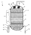
- the upward filtration device 1 includes a hollow pressure vessel 2 having a predetermined shape, a filter medium 3 provided in the pressure vessel 2, and the like.
- the pressure vessel 2 is made of a steel plate having a predetermined thickness, and has a cylindrical barrel portion 5, a dome-like head portion 6 that is liquid-tightly attached to the upper portion of the barrel portion 5, and a barrel portion as well. 5 and a dome-shaped bottom portion 7 that is liquid-tightly attached to the lower portion of 5. Since it is formed in such a shape, the pressure vessel 2 has high resistance to the internal pressure. Moreover, since the pressure vessel 2 can be easily disassembled, the filter medium 3 can be maintained and the internal members can be replaced.
- the upward filtration device 1 is characterized by a method of laminating the filter media 3.
- the lower filtration part 9 which filters the to-be-filtered water, and the particle
- the filtration part 3 is comprised from the several layer laminated
- the sand filter outflow prevention part 10 is laminated
- the filter media 3 stacked in this way are filled so as to reach the ceiling of the pressure vessel 2, that is, the head unit 6.
- the filter medium 3 since the filtration part 3 is comprised, even if a predetermined water pressure is applied to to-be-filtered water, the filter medium 3 is prevented from rising or rising. Moreover, in the upward filtration apparatus 1 which concerns on this Embodiment, the filter medium 3 does not soar not only at the time of filtration but at the time of washing
- the pressure vessel 2 has, at its lower end 13, a to-be-filtered water supply pipe 14 for supplying the to-be-filtered water into the pressure vessel 2, and a discharge pipe 15 for discharging the washing waste water when the filter medium 3 is washed to the outside.
- these pipes 14 and 15 are combined into a common pipe line, and the common pipe line is connected to the lower end portion 13 of the pressure vessel 2.
- a pump 16 for supplying filtered water with a water pressure of 0.05 MPa or more and a supply pipe valve 17 are interposed in the filtered water supply pipe 14.
- a drain pipe valve 18 is interposed in the drain pipe 15.
- a water supply pipe 21 for sending filtrate to the outside is connected to the upper end portion 20 of the pressure vessel 2.
- the supply pipe valve 17 is opened and the drain pipe valve 18 is closed.
- the pump 16 is driven to supply filtered water at a water pressure of 0.05 MPa or more. If it does so, to-be-filtered water will be supplied from the lower part of the pressure vessel 2, and will flow through the inside of the filtration part 9 of the filter medium 3 upward.
- the turbidity contained in the water to be filtered is filtered out in each layer of the filtration unit 9 according to the size of the particle size. Therefore, the to-be-filtered water will be filtered by the whole filtration part 9, and a turbidity will not concentrate only on a part of layer.
- the filtered water flows upward through the filtered sand outflow prevention unit 10 and is fed to the outside from the upper portion of the pressure vessel 2 through the water feeding pipe 21. Since the to-be-filtered water is pumped by the pump 16, even if turbidity accumulates in the filtration part 9, it can filter stably. When a large amount of turbidity accumulates in the filter medium 3, the filter medium 3 is washed. Specifically, the pump 16 is stopped and the supply pipe valve 17 is closed. Open the drain valve 18. In this way, purified water is pumped in the reverse direction from the water pipe 21. Then, the purified water flows downward in the filter medium 3.
- the turbidity is washed down by the purified water, the turbidity generally has a higher specific gravity than water, so the turbidity flows smoothly downward. That is, the filter medium 3 is washed. Water containing turbidity is drained through the drain pipe 15.
- the upward filtration device 1 can be applied to various uses, and the filter medium 3 is appropriately selected according to the use.
- the filter medium 3 is appropriately selected according to the use.
- the uppermost layer of the filtration unit 9 that is, the smallest particle
- the layer 11 is configured to be a filter sand layer having a particle size of 0.1 to 0.5 mm. If it filters with the filter medium 3 provided with such a filtration part 9, even if the turbidity of raw
- the upward filtration apparatus 1 can also be applied as an upward filtration apparatus that removes Cryptosporidium.
- a particle layer having a particle diameter of 1 to 50 ⁇ m is provided as the smallest particle layer 11 of the filtration unit 9.
- particles for example, ceramic particles, metal powder, glass particles and the like can be employed.
- the Cryptosporidium can be surely removed by constituting the filter medium 3 in this way, it is applied as an upward filtration device 1 for further processing water filtered by other filtration devices, slow filtration ponds, rapid filtration ponds, etc. can do. Furthermore, the upward filtration device 1 can be applied as a filtration device that can effectively decompose organic matter.
- the minimum particle layer 11 of the filtration unit 9 is made of diatomaceous earth. The particles constituting diatomaceous earth have a feature that the surface area is large because fine pores are formed. If it does so, aerobic bacteria will propagate easily, the organic substance in to-be-filtered water will be decomposed
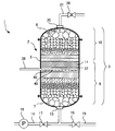
- FIG. 2 shows an upward filtration device 1 ′ according to the second embodiment.
- the upward filtration device 1 ′ according to the second embodiment is a filtration device obtained by modifying the upward filtration device 1 according to the previous embodiment, and members having the same functions are denoted by the same reference numerals and description thereof is omitted. To do.
- the upward filtration device 1 ′ according to the second embodiment is different from the upward filtration device 1 according to the previous embodiment in the following points.
- the first difference is that the filter medium 3 is not filled so as to reach the ceiling of the pressure vessel 2.
- a pressing plate 26 is provided on the filter medium 3, and the pressing plate 26 is biased downward by springs 25, 25. As a result, the filter medium 3 is pressed downward.
- the holding plate 26 has a large number of holes so that filtered water can pass therethrough, but the gravel constituting the uppermost layer of the filtered sand outflow portion 10 cannot pass therethrough.
- the water to be filtered is pumped into the pressure vessel 2 with a water pressure of 0.05 MPa or more, but the lifting of the filter medium 3 is suppressed by the press plate 26.
- the second difference is that the to-be-filtered water supply pipe 14 and the discharge pipe 15 are separately drawn into the pressure vessel 2 and embedded in the lower layer of the filtration unit 9. These pipes 14 and 15 are provided with a number of holes through which water to be filtered and drainage are passed.
- the upward filtration device 1 ′ according to the second embodiment also has the same effect as the upward filtration device 1 according to the previous embodiment.
- the filter medium 3 is pressed downward by the pressing plate 26 urged by the springs 25, 25, but the filter medium 3 is pressed downward by a predetermined weight. You may make it press on. Any member may be used as long as it is a member that can suppress the rising of the filter medium 3 against the water pressure of the supplied water to be filtered.
- the filtered water to be supplied can be modified. That is, a bactericide such as sodium hypochlorite may be injected into the water to be filtered supplied to the upward filtration device 1, or chemicals may not be injected.
- a bactericide such as sodium hypochlorite
- sodium hypochlorite When sodium hypochlorite is injected and the water to be filtered is supplied to the upward filtration device 1, microorganisms do not propagate on the filter medium 3, so that the effect of preventing clogging over a long period is obtained.
- water to be filtered is supplied to the upward filtration device 1 without injecting chemicals, microorganisms propagate in the filter medium 3 to form a biofilm.
- FIG. 3 shows an upward filtration device 1 that exhibits such an action.
- a fine bubble generating tank 28 is provided on the upstream side of the upward filtration device 1, and a fine bubble generating device 29 that generates air bubbles of 80 ⁇ m or less is placed in the fine bubble generating tank 28. .
- a swirling fine bubble generating device described in Japanese Patent No. 3397154 JP3397154
- a pump 16 that pumps filtered water to the filtered water supply pipe 14 is also placed in the fine bubble generating tank 28.
- the water to be filtered is once put in the fine bubble generating tank 28 and mixed by the fine bubble generating device 29 so that air bubbles of 10 to 80 ⁇ m become 200 bubbles / mL or more.
- the water to be filtered containing fine bubbles is supplied to the upward filtration device 1 via the pump 16 and the water to be filtered supply pipe 14. Since the air bubbles are sufficiently fine, the air bubbles flow through the filter medium 3 together with the water to be filtered and do not hinder the filtration. Since the water to be filtered contains sufficient oxygen, a thick biofilm made of aerobic bacteria is formed in the filter medium 3. If it does so, the organic substance in to-be-filtered water will be decomposed
- FIG. 1 An example to be described first is a filtration device in which two upward filtration devices 1a and 1b according to the present embodiment are combined, and is shown in FIG.
- “a” is added to members belonging to the first upward filtration device 1a
- “b” is added to members belonging to the second upward filtration device 2b.
- the first and second to-be-filtered water supply pipes 14a and 14b for supplying the to-be-filtered water to the first upward filtration devices 1a and 1b are branched from the to-be-filtered water supply main pipe 31 that is one pipe line.
- the pump 16 is interposed in the filtered water supply main pipe 31.
- first and second filtered water supply pipes 14a and 14b are respectively provided with first and second supply pipe valves 17a and 17b.
- the first and second drain pipes 15a and 15b connected to the first and second upward filtration devices 1a and 1b are respectively provided with first and second drain pipe valves 18a and 18b. Downstream, it joins the drainage main pipe 32.
- the first and second water supply pipes 21 a and 21 b connected to the first and second upward filtration devices 1 a and 1 b are in communication with each other and connected to the water supply main pipe 33.
- a water supply main valve 34 is interposed in the water supply main pipe 33.
- a filtration device composed of a combination of two upward filtration devices 1a and 1b
- the first and second supply pipe valves 17a and 17b and the water supply main valve 34 are opened, and the first and second drain pipe valves 18a and 18b are closed.
- the open valve is shown in white, and the closed valve is shown in black.
- the pump 16 is driven.
- the filtered water is supplied from the first and second filtered water supply pipes 14a and 14b to the first and second upward filtering devices 1a and 1b.
- the filtered water is filtered upward through the filter media 3a and 3b, and the filtered water flows from the first and second water supply pipes 21a and 21b to the water supply main pipe 33 and is supplied to the outside.
- the filtration time reaches a predetermined time
- one of the first and second upward filtration devices 1a and 1b is back-washed to wash the filter media 3a and 3b.
- the second upward filtration device 1b is washed, as shown in FIG. 5B, the first supply pipe valve 17a and the second drain pipe valve 18b are opened and the second supply pipe valve is opened. 17b, the first drain pipe valve 18a and the water main pipe valve 34 are closed. Then, the filtered water is supplied from the first filtered water supply pipe 14a to the first upward filtration device 1a and filtered, and the filtered water is fed from the first water feeding pipe 21a to the second water feeding pipe 21b.
- the filtered water sent is supplied to the second upward filtration device 1b and flows downward through the filter medium 3b. That is, the filter medium 3b is backwashed.
- the suspended matter accumulated in the filter medium 3b flows downward together with the filtered water, is discharged from the second drain pipe 15b, and is discharged to the outside through the drain main pipe 32.
- the second supply pipe valve 17b and the first drain pipe valve 18a are opened to supply the first supply.
- the pipe valve 17a, the second drain pipe valve 18b, and the water supply main valve 34 are closed.
- to-be-filtered water will be supplied to the 2nd upward filtration apparatus 1b from the 2nd supply pipe valve 17b, and will be filtered, and filtered water will be sent to the 1st water supply pipe 21a from the 2nd water supply pipe 21b.
- the filter medium 3a of the first upward filtration device 1a is back-washed by the fed filtered water, and the wash water is discharged from the first drain pipe 15a and discharged outside via the drain main pipe 32.
- the first and second supply pipe valves 17a and 17b and the water supply main valve 34 are opened, and the first and second drain pipe valves 18a and 18b are closed.
- the pump 16 When the pump 16 is driven, it can be filtered again.
- each valve 17a, 17b, 18a,... Is driven by a predetermined controller equipped with a timer, it can be backwashed automatically and periodically. In this way, when the first and second upward filtration devices 1a and 1b are combined, not only cleaning can be easily performed, but it is not necessary to store clean water for cleaning.
- an upward filtration device 1c according to a third embodiment that can wash the filter material 3 with filtered water will be described.
- the upward filtration device 1c according to the third embodiment is also configured similarly to the upward filtration device 1 according to the present embodiment, and as shown in FIG. 6, the upward filtration device 1 according to the present embodiment
- the same reference numerals are given to members having the same action.
- a cleaning pipe 38 for supplying filtered water for cleaning is embedded in the filtering unit 9 of the filter medium 3. More specifically, a cleaning tube 38 is embedded in a layer 37 adjacent to the smallest particle layer 11 below the smallest particle layer 11 of the filtration unit 9.
- a large number of small-diameter holes 40, 40,... are formed in the washing tube 38, and water to be filtered is ejected into the filter medium 3 from the holes, but the particles constituting the layer 37. Are not allowed to enter the cleaning tube 38 through the holes 40, 40,.
- a water pipe valve 36 is interposed in the water pipe 21.
- the supply pipe valve 17 and the water supply pipe valve 36 are opened as shown in FIG. Then, the drain pipe valve 18 is closed.
- the pump 16 is driven. If it does so, to-be-filtered water will be supplied to the pressure vessel 2 with the water pressure of 0.05 Mpa or more from the to-be-filtered water supply pipe
- FIG. The to-be-filtered water flows upward in the filter medium 3 and is filtered, and the filtered water is sent to the outside through the water pipe 21. If turbidity accumulates in the filter medium 3, the efficiency of filtration decreases.
- the filter medium 3 is washed as follows.
- the pump 16 is stopped and the supply pipe valve 17 and the water supply pipe valve 36 are closed as shown in FIG. Then, the drain pipe valve 18 is opened.
- water to be filtered is supplied from the cleaning pipe 38 at a predetermined water pressure, for example, 0.05 MPa or more. If it does so, the to-be-filtered water supplied from the washing pipe
- a predetermined amount of filtered water filtered by the upward filtration device 1c is stored in an external tank or the like.
- the pump 16 is stopped and the supply pipe valve 17 is closed as shown in FIG. Then, the water pipe valve 36 and the drain pipe valve 18 are opened.
- the stored filtered water is supplied from the water supply pipe 21 into the pressure vessel 2 at a predetermined water pressure. If it does so, filtered water will flow through the inside of the filter medium 3, and the turbidity in the filter medium 3 will also be pushed down together at this time. That is, the filter medium 3 can be washed. The washed waste water after washing is drained to the outside through the discharge pipe 15.
- the water pressure to be filtered was set to 0.05 MPa, and the others were tested under the same conditions as in Example 1.
Landscapes
- Chemical & Material Sciences (AREA)
- Chemical Kinetics & Catalysis (AREA)
- Life Sciences & Earth Sciences (AREA)
- Hydrology & Water Resources (AREA)
- Engineering & Computer Science (AREA)
- Environmental & Geological Engineering (AREA)
- Water Supply & Treatment (AREA)
- Organic Chemistry (AREA)
- Filtration Of Liquid (AREA)
- Filtering Materials (AREA)
Abstract
Description
請求項2に記載の発明は、圧力容器と、該圧力容器に入れられている砂利、ろ砂および粒子からなるろ過材とから構成され、被ろ過水を前記圧力容器の下部から供給して上向きにろ過すると前記圧力容器の上部からろ過水が得られるようになっている上向きろ過装置であって前記ろ過材は、下方から上方に向かって粒径が順次小さくなるように積層されているろ過部と、該ろ過部の上に下方から上方に向かって粒径が順次大きくなるように積層されているろ砂流出防止部とから構成され、前記被ろ過水は0.05MPa以上の水圧で前記圧力容器内に供給されるようになっており、前記ろ過材は、押さえ部材あるいはおもりによって上方から強制的に下に押し付けられて水圧による浮き上がりが抑制されていることを特徴とする上向きろ過装置として構成される。
請求項4に記載の発明は、請求項1または2に記載の上向きろ過装置において、前記ろ過部の最小の粒子の層は、粒径1~50μmの粒子の層からなることを特徴とする上向きろ過装置として構成される。
請求項5に記載の発明は、請求項1~4のいずれかの項に記載の上向きろ過装置において、前記被ろ過水は、80μm以下の径の空気の気泡が混入されて前記圧力容器に供給されるようになっていることを特徴とする上向きろ過装置として構成される。
請求項7に記載の発明は、請求項1~5のいずれかの項に記載の上向きろ過装置からなる第1、2の上向きろ過器が組み合わされているろ過装置であって、前記第1、2の上向きろ過装置は、ろ過水を上部から供給すると前記ろ過材が逆洗されて下部から洗浄水が排水されるようになっており、前記第1の上向きろ過器には、その下部に、第1の供給管弁が介装された第1の被ろ過水供給管と、第1の排水管弁が介装された第1の排水管とが設けられ、その上部に第1の送水管が設けられ、前記第2の上向きろ過器には、その下部に、第2の供給管弁が介装された第2の被ろ過水供給管と、第2の排水管弁が介装された第2の排水管とが設けられ、その上部に第2の送水管が設けられ、被ろ過水は、前記第1、2の被ろ過水供給管から0.05MPa以上の水圧で供給されるようになっており、前記第1、2の送水管は互いに連通していると共に送水本管弁が介装された送水本管が接続されていることを特徴とするろ過装置として構成される。
A.条件:
(1)圧力容器2の形状:半径4cmの円形
断面積:半径4cm×4cm×3.14=50.24cm2
(2)最小の粒子の層11:厚さ10mm:粒径1~50μmのセラミックス粒子。セラミックス粒子として、有限会社竹折砿業所の商品セラミックサンドを使用した。
(3)被ろ過水の水圧:0.1MPa
B.実験:
実験用の水槽に水道水を入れ、クリプトスポリジウムの疑似粒子を所定量添加して十分に攪拌した。次いで、水槽の水をポンプ16により加圧して上向きろ過装置1に圧送し、ろ過した。クリプトスポリジウムの疑似粒子には、日本光研工業株式会社および財団法人水道技術研究センターの商品「クリプトレーサー」(登録商標)を使用した。
C.結果:
(1)ろ過された水を調べたところ、クリプトスポリジウムの疑似粒子は発見されなかった。クリプトスポリジウムを完全に除去できることが確認できた。
(2)このとき、6分間で7,573cm3ろ過された。ろ過速度は7,573cm3/50.24cm2/6分=25cm/分であった。従って、ろ過速度は次のようになる。
25cm/分=15m/h=360m/日
C.結果:
(ア)クリプトスポリジウムの疑似粒子は発見されなかった。
(イ)毎時間当たり、あるいは毎日当たりのろ過速度は次の通りであった。
168m/日
最小の粒子の層11が、粒径1~50μmの粒子からなる上向きろ過装置1において、被ろ過水が確実にろ過されること、およびクリプトスポリジウムが確実に除去されることを確認することができた。
3 ろ過材 5 胴部
6 ヘッド部 7 ボトム部
9 ろ過部 10 ろ砂流出防止部
11 最小の粒子の層 14 被ろ過水供給管
15 排水管 16 ポンプ
17 供給管弁 18 排水管弁
21 送水管 26 押さえ板
28 微細気泡発生槽 29 微細気泡発生装置
38 洗浄管
Claims (7)
- 圧力容器と、該圧力容器に入れられている砂利、ろ砂および粒子からなるろ過材とから構成され、被ろ過水を前記圧力容器の下部から供給して上向きにろ過すると前記圧力容器の上部からろ過水が得られるようになっている上向きろ過装置であって、
前記ろ過材は、下方から上方に向かって粒径が順次小さくなるように積層されているろ過部と、該ろ過部の上に下方から上方に向かって粒径が順次大きくなるように積層されているろ砂流出防止部とから構成され、そして前記圧力容器の天井に達するように充填され、
前記被ろ過水は0.05MPa以上の水圧で前記圧力容器内に供給されるようになっていることを特徴とする上向きろ過装置。 - 圧力容器と、該圧力容器に入れられている砂利、ろ砂および粒子からなるろ過材とから構成され、被ろ過水を前記圧力容器の下部から供給して上向きにろ過すると前記圧力容器の上部からろ過水が得られるようになっている上向きろ過装置であって
前記ろ過材は、下方から上方に向かって粒径が順次小さくなるように積層されているろ過部と、該ろ過部の上に下方から上方に向かって粒径が順次大きくなるように積層されているろ砂流出防止部とから構成され、
前記被ろ過水は0.05MPa以上の水圧で前記圧力容器内に供給されるようになっており、
前記ろ過材は、押さえ部材あるいはおもりによって上方から強制的に下に押し付けられて水圧による浮き上がりが抑制されていることを特徴とする上向きろ過装置。 - 請求項1または2に記載の上向きろ過装置において、前記ろ過部の最小の粒子の層は、粒径0.1~0.5mmのろ砂の層からなることを特徴とする上向きろ過装置。
- 請求項1または2に記載の上向きろ過装置において、前記ろ過部の最小の粒子の層は、粒径1~50μmの粒子の層からなることを特徴とする上向きろ過装置。
- 請求項1~4のいずれかの項に記載の上向きろ過装置において、前記被ろ過水は、80μm以下の径の空気の気泡が混入されて前記圧力容器に供給されるようになっていることを特徴とする上向きろ過装置。
- 請求項1~5のいずれかの項に記載の上向きろ過装置において、前記圧力容器の下部には供給管弁が介装された被ろ過水供給管と、排水管弁が介装された排水管とが設けられ、前記圧力容器の上部には送水管弁が介装された送水管が設けられ、そして前記ろ過部の前記最小の粒子の層の下に隣接している層には、多数の孔が明けられた洗浄管が埋設され、
前記供給管弁と前記送水管弁を開けると共に前記排水管弁を閉じ、前記被ろ過水供給管から被ろ過水を供給すると、前記ろ過材によってろ過されたろ過水が前記送水管から外部に供給され、
前記供給管弁と前記送水管弁を閉じると共に前記排水管弁を開け、前記洗浄管から被ろ過水を供給すると、被ろ過水によって前記ろ過材が洗浄されて前記排水管から排水されるようになっていることを特徴とする上向きろ過装置。 - 請求項1~5のいずれかの項に記載の上向きろ過装置からなる第1、2の上向きろ過器が組み合わされているろ過装置であって、
前記第1、2の上向きろ過装置は、ろ過水を上部から供給すると前記ろ過材が逆洗されて下部から洗浄水が排水されるようになっており、
前記第1の上向きろ過器には、その下部に、第1の供給管弁が介装された第1の被ろ過水供給管と、第1の排水管弁が介装された第1の排水管とが設けられ、その上部に第1の送水管が設けられ、
前記第2の上向きろ過器には、その下部に、第2の供給管弁が介装された第2の被ろ過水供給管と、第2の排水管弁が介装された第2の排水管とが設けられ、その上部に第2の送水管が設けられ、
被ろ過水は、前記第1、2の被ろ過水供給管から0.05MPa以上の水圧で供給されるようになっており、前記第1、2の送水管は互いに連通していると共に送水本管弁が介装された送水本管が接続されていることを特徴とするろ過装置。
Priority Applications (6)
| Application Number | Priority Date | Filing Date | Title |
|---|---|---|---|
| EP11828270.6A EP2609977A1 (en) | 2010-09-28 | 2011-04-11 | Up-flow filtration device characterized by method for stacking filter materials |
| US13/264,038 US8864989B2 (en) | 2010-09-28 | 2011-04-11 | Upward-type filtering apparatus characterized in laminating method of filtering material |
| SG2013023759A SG188665A1 (en) | 2010-09-28 | 2011-04-11 | Up-flow filtration device characterized by method for stacking filter materials |
| CA 2810635 CA2810635A1 (en) | 2010-09-28 | 2011-04-11 | Upward-type filtering apparatus characterized in laminating method of filtering material |
| CN201180004770.8A CN102781535B (zh) | 2010-09-28 | 2011-04-11 | 在过滤基材积层方法上具有独特性的上流式过滤装置 |
| KR20137010440A KR20130079557A (ko) | 2010-09-28 | 2011-04-11 | 여과재 적층방법에 특징으로 가지는 상향 여과 장치 |
Applications Claiming Priority (4)
| Application Number | Priority Date | Filing Date | Title |
|---|---|---|---|
| JP2010006423U JP3164640U (ja) | 2010-09-28 | 2010-09-28 | 微細な濁質除去用のろ過装置 |
| JP2010-006423U | 2010-09-28 | ||
| JP2010272106A JP4803685B1 (ja) | 2010-12-07 | 2010-12-07 | 濁質除去用のろ過装置 |
| JP2010-272106 | 2010-12-07 |
Publications (1)
| Publication Number | Publication Date |
|---|---|
| WO2012042700A1 true WO2012042700A1 (ja) | 2012-04-05 |
Family
ID=45892199
Family Applications (1)
| Application Number | Title | Priority Date | Filing Date |
|---|---|---|---|
| PCT/JP2011/002115 WO2012042700A1 (ja) | 2010-09-28 | 2011-04-11 | ろ過材の積層方法に特徴を有する上向きろ過装置 |
Country Status (8)
| Country | Link |
|---|---|
| US (1) | US8864989B2 (ja) |
| EP (1) | EP2609977A1 (ja) |
| KR (1) | KR20130079557A (ja) |
| CN (1) | CN102781535B (ja) |
| CA (1) | CA2810635A1 (ja) |
| SG (1) | SG188665A1 (ja) |
| TW (1) | TWI473641B (ja) |
| WO (1) | WO2012042700A1 (ja) |
Cited By (5)
| Publication number | Priority date | Publication date | Assignee | Title |
|---|---|---|---|---|
| JP5698881B1 (ja) * | 2014-08-08 | 2015-04-08 | 和典 小石 | ろ過方法およびろ過装置 |
| JP2016019941A (ja) * | 2014-07-14 | 2016-02-04 | 東京都下水道サービス株式会社 | 流路洗浄装置及び流路洗浄装置を備えたフィルタ洗浄設備 |
| CN105817064A (zh) * | 2016-05-06 | 2016-08-03 | 淄博格瑞水处理工程有限公司 | 一种集成微滤装置 |
| TWI558313B (zh) * | 2014-03-07 | 2016-11-21 | tian-wang Xiao | Method for manufacturing microbial culture filter |
| CN107935120A (zh) * | 2017-12-25 | 2018-04-20 | 天津珑源新材料科技有限公司 | 一种前置预处理的碟管式反渗透膜一体化膜分离装置及pH敏感型导流盘 |
Families Citing this family (8)
| Publication number | Priority date | Publication date | Assignee | Title |
|---|---|---|---|---|
| CN105879441B (zh) * | 2016-05-23 | 2018-08-31 | 鄂尔多斯市紫荆低碳生产力促进中心有限公司 | 一种基于模块化分离组件的集成过滤净水系统 |
| US10913667B2 (en) * | 2017-12-08 | 2021-02-09 | Westech Engineering, Inc. | Multi-media clarification systems and methods |
| FR3081728A1 (fr) * | 2018-05-29 | 2019-12-06 | Veolia Water Solutions & Technologies Support | Reacteur pour la decantation et la filtration d'une eau a traiter, procede de traitement et de lavage correspondants et installation le comprenant |
| CN108840510B (zh) * | 2018-06-12 | 2020-12-01 | 江南大学 | 一种短流程含油废水中烷烃类物质的处理方法 |
| CN112121479A (zh) * | 2019-06-24 | 2020-12-25 | 吉林嘉德蓝天环境技术有限公司 | 一种延长滤料使用寿命的高效承托层结构 |
| US11589563B2 (en) * | 2019-07-24 | 2023-02-28 | Verily Life Sciences Llc | Pupae transfer device |
| RU2749272C2 (ru) * | 2020-02-18 | 2021-06-07 | Юрий Алексеевич Ищенко | Способ интенсификации ресурсосберегающим дельта-фильтрованием технологий водоподготовки |
| CN113921152B (zh) * | 2021-09-27 | 2023-12-22 | 中国船舶重工集团公司第七一九研究所 | 一种安全壳卸压排气活度监测系统 |
Citations (6)
| Publication number | Priority date | Publication date | Assignee | Title |
|---|---|---|---|---|
| JPS4422059Y1 (ja) * | 1966-02-04 | 1969-09-18 | ||
| JPS458312Y1 (ja) * | 1966-12-28 | 1970-04-20 | ||
| JPH03119066U (ja) * | 1990-03-15 | 1991-12-09 | ||
| JP2001137616A (ja) * | 1999-11-15 | 2001-05-22 | Japan Organo Co Ltd | ろ過装置 |
| JP3397154B2 (ja) | 1997-12-30 | 2003-04-14 | 博文 大成 | 旋回式微細気泡発生装置 |
| JP3769561B2 (ja) | 2003-09-22 | 2006-04-26 | 岡田産業株式会社 | 上向ろ過装置 |
Family Cites Families (13)
| Publication number | Priority date | Publication date | Assignee | Title |
|---|---|---|---|---|
| US2101961A (en) * | 1934-10-31 | 1937-12-14 | Burgess Lab Inc C F | Treatment of water |
| US4139473A (en) * | 1977-09-12 | 1979-02-13 | Alldredge Robert L | Filter |
| US4246119A (en) * | 1979-02-12 | 1981-01-20 | Alldredge Robert L | Liquid sand filter |
| JPS6075677U (ja) | 1983-10-31 | 1985-05-27 | いすゞ自動車株式会社 | 内燃機関の燃料噴射装置 |
| US4643833A (en) * | 1984-05-04 | 1987-02-17 | Siemens Aktiengesellschaft | Method for separating solid reaction products from silicon produced in an arc furnace |
| JPS62133480A (ja) | 1985-12-04 | 1987-06-16 | コマニー株式会社 | 角度つき旗さし蝶番を用いたドア構造 |
| CN2046764U (zh) * | 1988-11-22 | 1989-11-01 | 许文斌 | 水质净化预处理装置 |
| TW216773B (ja) * | 1991-06-21 | 1993-12-01 | Johnson Filtration Systems | |
| US5750041A (en) * | 1994-08-15 | 1998-05-12 | Hirane; Ken | Method for backwashing water processing systems |
| CN1257000C (zh) * | 2003-06-19 | 2006-05-24 | 清华同方股份有限公司 | 一种上向流可压缩的过滤系统 |
| JP3119066U (ja) | 2005-11-04 | 2006-02-16 | 政実 土本 | 濾過器 |
| JPWO2008010452A1 (ja) * | 2006-07-20 | 2009-12-17 | 日本碍子株式会社 | セラミックフィルタ |
| CN201283252Y (zh) * | 2008-10-21 | 2009-08-05 | 上海乐泽环境工程有限公司 | 高浊度过滤器 |
-
2011
- 2011-04-11 SG SG2013023759A patent/SG188665A1/en unknown
- 2011-04-11 KR KR20137010440A patent/KR20130079557A/ko not_active Application Discontinuation
- 2011-04-11 US US13/264,038 patent/US8864989B2/en not_active Expired - Fee Related
- 2011-04-11 CN CN201180004770.8A patent/CN102781535B/zh not_active Expired - Fee Related
- 2011-04-11 WO PCT/JP2011/002115 patent/WO2012042700A1/ja active Application Filing
- 2011-04-11 EP EP11828270.6A patent/EP2609977A1/en not_active Withdrawn
- 2011-04-11 CA CA 2810635 patent/CA2810635A1/en not_active Abandoned
- 2011-04-18 TW TW100113375A patent/TWI473641B/zh not_active IP Right Cessation
Patent Citations (6)
| Publication number | Priority date | Publication date | Assignee | Title |
|---|---|---|---|---|
| JPS4422059Y1 (ja) * | 1966-02-04 | 1969-09-18 | ||
| JPS458312Y1 (ja) * | 1966-12-28 | 1970-04-20 | ||
| JPH03119066U (ja) * | 1990-03-15 | 1991-12-09 | ||
| JP3397154B2 (ja) | 1997-12-30 | 2003-04-14 | 博文 大成 | 旋回式微細気泡発生装置 |
| JP2001137616A (ja) * | 1999-11-15 | 2001-05-22 | Japan Organo Co Ltd | ろ過装置 |
| JP3769561B2 (ja) | 2003-09-22 | 2006-04-26 | 岡田産業株式会社 | 上向ろ過装置 |
Cited By (6)
| Publication number | Priority date | Publication date | Assignee | Title |
|---|---|---|---|---|
| TWI558313B (zh) * | 2014-03-07 | 2016-11-21 | tian-wang Xiao | Method for manufacturing microbial culture filter |
| JP2016019941A (ja) * | 2014-07-14 | 2016-02-04 | 東京都下水道サービス株式会社 | 流路洗浄装置及び流路洗浄装置を備えたフィルタ洗浄設備 |
| JP5698881B1 (ja) * | 2014-08-08 | 2015-04-08 | 和典 小石 | ろ過方法およびろ過装置 |
| WO2016020957A1 (ja) * | 2014-08-08 | 2016-02-11 | 和典 小石 | ろ過方法およびろ過装置 |
| CN105817064A (zh) * | 2016-05-06 | 2016-08-03 | 淄博格瑞水处理工程有限公司 | 一种集成微滤装置 |
| CN107935120A (zh) * | 2017-12-25 | 2018-04-20 | 天津珑源新材料科技有限公司 | 一种前置预处理的碟管式反渗透膜一体化膜分离装置及pH敏感型导流盘 |
Also Published As
| Publication number | Publication date |
|---|---|
| CN102781535A (zh) | 2012-11-14 |
| TWI473641B (zh) | 2015-02-21 |
| CA2810635A1 (en) | 2012-04-05 |
| KR20130079557A (ko) | 2013-07-10 |
| US20120138524A1 (en) | 2012-06-07 |
| EP2609977A1 (en) | 2013-07-03 |
| TW201212994A (en) | 2012-04-01 |
| SG188665A1 (en) | 2013-05-31 |
| US8864989B2 (en) | 2014-10-21 |
| CN102781535B (zh) | 2014-09-03 |
Similar Documents
| Publication | Publication Date | Title |
|---|---|---|
| WO2012042700A1 (ja) | ろ過材の積層方法に特徴を有する上向きろ過装置 | |
| KR100860079B1 (ko) | 수 처리기의 상향류식 여과 및 역세 방법 및 그 장치 | |
| JP2010264334A (ja) | 水処理装置および水処理装置濾材層の洗浄方法 | |
| JP5989437B2 (ja) | 水処理システムおよび水処理方法 | |
| EP2498891B1 (en) | A method and a plant for the treatment of water and wastewater | |
| JP2007289847A (ja) | 水道原水の浄水処理方法及びその装置 | |
| JP4721239B1 (ja) | ろ過材の積層方法に特徴を有する上向きろ過装置 | |
| JP4803685B1 (ja) | 濁質除去用のろ過装置 | |
| KR101541070B1 (ko) | 고도처리장치 | |
| JP5801249B2 (ja) | 淡水化装置及び淡水化方法 | |
| JP4591678B2 (ja) | 生物処理装置 | |
| JP3164640U (ja) | 微細な濁質除去用のろ過装置 | |
| JP2011110533A (ja) | 上向きろ過装置 | |
| JP4908542B2 (ja) | ろ過方法、ろ過装置およびろ過池 | |
| JP2014018741A (ja) | 微細粒子ろ過材を備えた上向きろ過装置 | |
| JP5698881B1 (ja) | ろ過方法およびろ過装置 | |
| KR200471174Y1 (ko) | 초고속 여과기능과 미세여재의 회수기능을 구비한 여과장치 | |
| JP4335193B2 (ja) | 有機性廃水の処理方法及び装置 | |
| KR101298063B1 (ko) | 하천 및 호소의 조류제거 장치 | |
| JP5754649B2 (ja) | 深層ろ過装置 | |
| JP3173319U (ja) | ろ過装置 | |
| JP4124957B2 (ja) | ろ過体の洗浄方法及び装置 | |
| JP2010207743A (ja) | クリプトスポリジウムの除去方法および除去装置 | |
| KR101543503B1 (ko) | 멤브레인을 결합한 원통형의 용존가압부상 수처리장치 | |
| JP2006255512A (ja) | 排水処理方法およびその設備 |
Legal Events
| Date | Code | Title | Description |
|---|---|---|---|
| WWE | Wipo information: entry into national phase |
Ref document number: 201180004770.8 Country of ref document: CN |
|
| WWE | Wipo information: entry into national phase |
Ref document number: 13264038 Country of ref document: US |
|
| WWE | Wipo information: entry into national phase |
Ref document number: 1201000292 Country of ref document: TH |
|
| 121 | Ep: the epo has been informed by wipo that ep was designated in this application |
Ref document number: 11828270 Country of ref document: EP Kind code of ref document: A1 |
|
| WWE | Wipo information: entry into national phase |
Ref document number: 12013500428 Country of ref document: PH |
|
| ENP | Entry into the national phase |
Ref document number: 2810635 Country of ref document: CA |
|
| WWE | Wipo information: entry into national phase |
Ref document number: 2011828270 Country of ref document: EP |
|
| NENP | Non-entry into the national phase |
Ref country code: DE |
|
| ENP | Entry into the national phase |
Ref document number: 20137010440 Country of ref document: KR Kind code of ref document: A |