WO2012042678A1 - 計算機システム及び計算機システムの管理方法 - Google Patents
計算機システム及び計算機システムの管理方法 Download PDFInfo
- Publication number
- WO2012042678A1 WO2012042678A1 PCT/JP2010/069222 JP2010069222W WO2012042678A1 WO 2012042678 A1 WO2012042678 A1 WO 2012042678A1 JP 2010069222 W JP2010069222 W JP 2010069222W WO 2012042678 A1 WO2012042678 A1 WO 2012042678A1
- Authority
- WO
- WIPO (PCT)
- Prior art keywords
- pool
- volume
- predetermined
- real
- size
- Prior art date
- Legal status (The legal status is an assumption and is not a legal conclusion. Google has not performed a legal analysis and makes no representation as to the accuracy of the status listed.)
- Ceased
Links
Images


Classifications
-
- G—PHYSICS
- G06—COMPUTING OR CALCULATING; COUNTING
- G06F—ELECTRIC DIGITAL DATA PROCESSING
- G06F3/00—Input arrangements for transferring data to be processed into a form capable of being handled by the computer; Output arrangements for transferring data from processing unit to output unit, e.g. interface arrangements
- G06F3/06—Digital input from, or digital output to, record carriers, e.g. RAID, emulated record carriers or networked record carriers
- G06F3/0601—Interfaces specially adapted for storage systems
- G06F3/0628—Interfaces specially adapted for storage systems making use of a particular technique
- G06F3/0638—Organizing or formatting or addressing of data
- G06F3/0644—Management of space entities, e.g. partitions, extents, pools
-
- G—PHYSICS
- G06—COMPUTING OR CALCULATING; COUNTING
- G06F—ELECTRIC DIGITAL DATA PROCESSING
- G06F3/00—Input arrangements for transferring data to be processed into a form capable of being handled by the computer; Output arrangements for transferring data from processing unit to output unit, e.g. interface arrangements
- G06F3/06—Digital input from, or digital output to, record carriers, e.g. RAID, emulated record carriers or networked record carriers
- G06F3/0601—Interfaces specially adapted for storage systems
- G06F3/0602—Interfaces specially adapted for storage systems specifically adapted to achieve a particular effect
- G06F3/0604—Improving or facilitating administration, e.g. storage management
- G06F3/0607—Improving or facilitating administration, e.g. storage management by facilitating the process of upgrading existing storage systems, e.g. for improving compatibility between host and storage device
-
- G—PHYSICS
- G06—COMPUTING OR CALCULATING; COUNTING
- G06F—ELECTRIC DIGITAL DATA PROCESSING
- G06F3/00—Input arrangements for transferring data to be processed into a form capable of being handled by the computer; Output arrangements for transferring data from processing unit to output unit, e.g. interface arrangements
- G06F3/06—Digital input from, or digital output to, record carriers, e.g. RAID, emulated record carriers or networked record carriers
- G06F3/0601—Interfaces specially adapted for storage systems
- G06F3/0628—Interfaces specially adapted for storage systems making use of a particular technique
- G06F3/0629—Configuration or reconfiguration of storage systems
- G06F3/0631—Configuration or reconfiguration of storage systems by allocating resources to storage systems
-
- G—PHYSICS
- G06—COMPUTING OR CALCULATING; COUNTING
- G06F—ELECTRIC DIGITAL DATA PROCESSING
- G06F3/00—Input arrangements for transferring data to be processed into a form capable of being handled by the computer; Output arrangements for transferring data from processing unit to output unit, e.g. interface arrangements
- G06F3/06—Digital input from, or digital output to, record carriers, e.g. RAID, emulated record carriers or networked record carriers
- G06F3/0601—Interfaces specially adapted for storage systems
- G06F3/0668—Interfaces specially adapted for storage systems adopting a particular infrastructure
- G06F3/067—Distributed or networked storage systems, e.g. storage area networks [SAN], network attached storage [NAS]
Definitions
- the present invention relates to a computer system and a computer system management method.
- Large storage is also called a storage subsystem, which not only enables high-speed and large-capacity data storage, but also has advanced data management functions.
- a plurality of physical storage devices such as hard disk drives are mounted in the storage.
- a logical volume which is a logical storage area, is configured using the storage areas in these storage devices.
- the storage apparatus provides a logical volume to the host computer. The host computer reads / writes data from / to the logical volume.
- Thin provisioning technology provides a host with a virtual logical volume (hereinafter referred to as a virtual volume) in place of a conventional logical volume.
- a conventional logical volume requires a physical storage area (real storage area) of a size specified at the time of volume creation.
- a real storage area for storing the data is taken out of the pool and assigned to the virtual volume.
- the thin provisioning technology it is not necessary to allocate a real storage area to a virtual volume until data is actually written, so that the real storage area can be saved.
- the amount of data written to the virtual volume may exceed the size of the real storage area that can be allocated to the virtual volume. If the real storage area to be allocated to the virtual volume is insufficient, an error may occur.
- the thin provisioning technology when used, it is preferable to accurately manage the amount of the real storage area (actual usage amount) that can be allocated to the virtual volume.
- an object of the present invention is to reduce the burden on the administrator and expand the pool size by selecting and executing at least one method from a plurality of methods based on a predetermined selection criterion.
- the object is to provide a computer system and a management method of the computer system.
- a computer system includes a plurality of storage control devices that generate at least one virtual logical volume, at least one host computer that uses a virtual logical volume, and each storage control.
- a computer system including an apparatus and at least one management computer for managing a host computer, wherein each storage control device has a real storage area of a real volume in a pool in response to a write access from the host computer Is assigned to a virtual logical volume, and write data received from the host computer is stored in the allocated real storage area.
- the management computer is read and executed by the microprocessor and the microprocessor.
- Memory for storing a predetermined computer program and each storage control device And a communication interface unit for communicating with the host computer, and the microprocessor reads and executes a predetermined computer program to obtain the use state of each pool, and the obtained use state of each pool And (A) a volume addition method for adding an unused real volume to the predetermined pool when a predetermined pool is detected and whether or not there is a predetermined pool that needs to be expanded. (B) At least one method is selected based on a predetermined selection criterion among data movement methods for moving data of a virtual logical volume to another pool other than the predetermined pool, and according to the selected method Increase the pool size of a given pool.
- the microprocessor can expand the pool size of a given pool within a given time in consideration of the operating status of application programs that use virtual logical volumes. It can also be determined whether or not it is completed.
- the volume addition method may include a first volume addition method for adding an unused first real volume, which is included in a predetermined storage control device to which a predetermined pool belongs among the storage control devices, to the predetermined pool. .
- the volume size of the first real volume, the attribute label preset in the predetermined pool, and the first real volume are preset as the predetermined selection criteria. It is also possible to consider the conformity state with the attribute label being used and the response performance of the predetermined pool when the first real volume is added to the predetermined pool.
- the second real volume of each storage controller other than the predetermined storage controller is connected to the predetermined storage controller, so that the second A second volume addition method for adding an unused real volume to a predetermined pool may be included.
- the third real volume provided in the first other pool of the predetermined storage control device is removed from each storage control device, and the removed third real volume is unused.
- a third volume addition method may be included in which a real volume is added to the predetermined pool.
- the fourth real volume provided in the second other pool of the other storage control device other than the predetermined storage control device is removed, and the removed fourth real volume is removed.
- a fourth volume addition method for adding an unused real volume to a predetermined pool may be included.
- the data movement method may include a first data movement method in which the host computer moves the data of the virtual logical volume to a pool other than the predetermined pool.
- the data movement method may include a second data movement method in which a predetermined storage controller moves data of a virtual logical volume to a pool other than the predetermined pool.
- the present invention can also be understood as a computer program or a recording medium for recording a computer program. Furthermore, the present invention is not limited to the combination of the above-described viewpoints, and can include combinations other than those.
- FIG. 1 is an overall configuration diagram of a computer system according to the present embodiment.
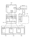
- FIG. 2 is a diagram schematically illustrating a pool size expansion method.
- FIG. 3 is a diagram illustrating information on virtual volumes used by the host.
- FIG. 4 is a diagram showing storage information.
- FIG. 5 is a diagram illustrating pool information.
- FIG. 6 is a diagram showing information on unused volumes.
- FIG. 7 is a diagram illustrating management policy information.
- FIG. 8 is a flowchart of processing for monitoring the usage rate of the pool.
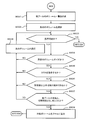
- FIG. 9 is a flowchart of processing for expanding the pool size.
- FIG. 10 is a flowchart showing a process for expanding the pool size in its own storage.
- FIG. 11 is a flowchart of processing for moving a virtual volume.
- FIG. 1 is an overall configuration diagram of a computer system according to the present embodiment.
- FIG. 2 is a diagram schematically illustrating a pool size expansion method.
- FIG. 3 is a diagram
- FIG. 12 is a flowchart showing processing for expanding the pool size using another storage.
- FIG. 13 is a flowchart showing a process for expanding a pool size by diverting a volume used in another pool.
- FIG. 14 is a schematic diagram showing how a real storage area in a pool is allocated to a virtual volume and the effect obtained when the host computer moves the virtual volume.
- Measures may be selected based on the following viewpoints, for example.
- Virtual volumes, real volumes (logical volumes), and pools have attributes (for example, performance, price, department, etc.) according to their configuration or purpose. If these attributes are ignored and the virtual volume is moved to another pool or a real volume is freely added to the pool, the usability and the like may decrease. For example, a virtual volume that requires a high-speed response is moved to a pool with low response performance, or a virtual volume that requires high reliability is moved to a pool with low reliability. Furthermore, for example, when a low-speed logical volume is added to a pool composed of high-speed logical volumes, the response performance of the pool decreases. Therefore, an attribute label (referred to as “category” in the embodiment described later) is set for the virtual volume, logical volume, and pool, and a countermeasure is selected so that the attribute label matches.
- attributes for example, performance, price, department, etc.
- FIG. 1 is an overall configuration diagram of a computer system according to this embodiment.
- the computer system includes, for example, at least one management terminal 10, at least one management computer 20, a plurality of storages 30, at least one host computer 40, a management network 51, and a storage network 52.
- the management terminal 10, the management computer 20, each storage 30 and the host computer 40 are connected by a management network 51 so that bidirectional communication is possible. Furthermore, the management computer 20, each storage 30 and the host computer 40 are connected by a storage network 52 so that bidirectional communication is possible.
- the management network 51 and the storage network 52 are communication lines, and are communication paths for transmitting and receiving data between information processing apparatuses.
- the management network 51 and the storage network 52 are shown as separate communication lines, but both networks 51 and 52 may be configured as a common communication line.
- the management terminal 10 is an information processing apparatus.
- the memory 11 a microprocessor (CPU in the figure) 12, a display device 13, a keyboard 14, a mouse 15, a host interface (hereinafter referred to as an I / O interface).
- I / O interface a host interface
- F and display 16.
- the memory 11 stores data and computer programs.
- a microprocessor (hereinafter referred to as a processor) 12 reads a computer program from the memory 11 and executes it.
- the display device 13 displays data and the like.
- the keyboard 14 receives input by characters from the user.
- the mouse 15 is used to point to an arbitrary point on the screen displayed on the display device.
- the host I / F 16 transmits / receives data to / from the management computer 20 via the management network 51.
- the user interface is not limited to a display device, a keyboard, and a mouse.
- a voice instruction device, an electroencephalogram instruction device, or the like can be used.
- the console program 111 is stored in the memory 11.
- the processor 12 executes the console program 111, a function of exchanging data with the management computer 20 via the host I / F 16 and the management network 51, a function of displaying information on the display device 13, a keyboard 14 and a mouse 15 and a function of accepting an input from the user via 15.
- the management terminal 10 is used as a window for a user (storage administrator) who is involved in storage operation and management to operate and manage the storage 30.
- the management computer 20 is an information processing apparatus, and includes, for example, a memory 21, a processor 22, a SAN I / F 23, and a host I / F 24.
- the memory 21 stores data and computer programs.
- the processor 22 reads a computer program from the memory 21 and executes it. Thereby, each function mentioned later is realized.
- the SAN I / F 23 is a circuit for performing an operation instruction or information inquiry to each storage 30 via the storage network 52.
- the host I / F 24 is a circuit for data communication with the other information processing apparatuses 10, 30, and 40 via the management network 51.
- the management server program 211 is a computer program for managing each storage 30 and is stored in the memory 21.
- the host-volume information 212 is information for managing the configuration and usage of the virtual volume used on the host computer 40.
- the storage information 213 is information for managing the functions installed in each storage 30.
- the pool information 214 is information for managing the configuration and usage status of each pool.
- the unused volume information 215 is information regarding unused volumes in each storage 30.
- the management policy information 216 is information that defines the operation of the management server program 211.
- Host-volume information 212, storage information 213, pool information 214, unused volume information 215, and management policy information 216 are stored in the memory 21. Details of the information 212, 213, 214, 215, 216 will be described later.
- FIG. 1 shows a case where the management computer 20 and the host computer 40 are separately configured, the host computer 40 may be made to realize the function of the management computer instead.
- the computer program 211 and the various management information 212 to 216 of the management computer 20 may be provided in at least one of the plurality of host computers 40.
- Each storage 30 as a “storage control device” is a device for storing information.
- Each storage 30 includes, for example, a storage controller 31 and a disk unit 32.
- the storage controller 31 includes a host I / F 311, a SAN I / F 312, a microprocessor 313, a memory 314, and a disk controller 315.
- the host I / F 311 is a circuit for connecting to the management network 51.
- the SAN I / F 312 is a circuit for connecting to the storage network 52.
- an input / output processing program (I / O program in the figure) 3141 for example, an input / output processing program (I / O program in the figure) 3141, a volume migration program (migration program in the figure) 3142, and a thin provisioning program 3143 are stored.
- the microprocessor 313 reads and executes these computer programs 3141, 3142, 3143.
- the disk controller 315 controls reading and writing of data with respect to the disk drive 321.
- the disk unit 32 includes a plurality of disk drives 321. It is possible to group physical storage areas that each disk drive 321 has, and to set a plurality of logical storage areas in the grouped physical storage areas.
- the logical storage area is called a logical volume 322.
- the disk drive for example, various devices capable of reading and writing data such as a hard disk drive, a semiconductor memory drive, an optical disk drive, and a magneto-optical disk drive can be used.
- FC Fibre Channel
- SCSI Serial Computer System Interface
- SATA Serial Advanced Technology Attachment
- SAS Serial Attached SCSI
- flash memory FeRAM (Ferroelectric Random Access Memory), MRAM (Magnetoresistive Random Access)
- MRAM Magneticoresistive Random Access
- Various storage devices such as “Memory”, phase change memory (Ovonic Unified Memory), and RRAM (Resistance RAM) can also be used.
- the input / output processing program 3141 defines a logical volume in response to a request from the management computer 20. Further, the input / output processing program 3141 reads / writes data from / to the logical volume and virtual volume in response to a request from the host computer 40.
- the volume migration program 3142 migrates the virtual volume to another pool in response to an instruction from the management computer 20. A description of the virtual volume and the pool will be described later with reference to FIG.
- the thin provisioning program 3143 provides, for example, pool configuration management, pool operation management, virtual volume configuration management, virtual volume operation management, data read / write function, and the like.
- the host computer 40 is an information processing apparatus, and includes, for example, a SAN I / F 41, a host I / F 42, a processor 43, and a memory 40.
- the SAN I / F 41 is a circuit for data communication with each storage 30 via the storage network 52.
- the host I / F 42 is a circuit for data communication with the management computer 20 via the management network 51.
- a management agent program 441 for example, a management agent program 441, a migration program (also referred to as a volume migration program) 442, an application program 443, and an OS (operating system) 444 are stored.
- the processor 43 reads and executes each computer program 441, 442, 443.
- the management agent program 441 executes the volume migration program 442 based on an instruction from the management server program 211.
- the volume migration program 442 is a program for migrating data of a logical volume or a virtual volume to another logical volume or another virtual volume.
- the application program 443 is a program for executing business processing on the host computer 40.
- the OS 444 is basic software that is an execution base of the management agent program 441 and the application program 443.
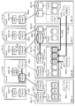
- FIG. 2 is a conceptual diagram showing a logical configuration of an information processing system using the thin provisioning technology and a coping method when the pool capacity is insufficient.
- the storage 30 (1) is a storage specified by an identification name “DKC-A”.
- the storage 30 (1) includes a pool 611 identified by an identification name “POOL-A”.
- the pool 611 includes a plurality of logical volumes 621, 622, and 623. To the pool 611, a virtual volume 631 identified by an identification name “VVOL-A” and a virtual volume 632 identified by an identification name “VVOL-B” belong.
- the virtual volume 631 is a volume 651 specified by the identification name “VOL-A” on the host computer 40 (1).
- the volume 651 is used from the application program 443 (1) specified by the identification name “AP-A”. In such a configuration, when the application program 443 (1) writes data to the volume 651, the following processing is performed.
- the OS 444 that has received a write request for the volume 651 issues a write request to the virtual volume 631 corresponding to the volume 651 to the storage 30 (1).
- the input / output processing program 3141 in the storage 30 (1) that has received the write request notifies the thin provisioning program 3143 that there has been a write request.
- the thin provisioning program 3143 receives the notification, it is determined whether or not the storage area (real page or chunk) in the pool 611 has been allocated to the write target storage area (virtual page) among all the storage areas of the virtual volume 631. Determine.
- the thin provisioning program 3143 determines that the real page is not allocated to the write target virtual page, the thin provision program 3143 selects the real page from the real storage area of each logical volume configuring the pool 611, and Assign to a virtual page.
- the data from the application program 443 (1) is written in the real page assigned to the virtual page.
- the data written from the application program 443 (1) is stored in the assigned real page.
- the above processing is similarly performed for the virtual volume 632 sharing the pool 611, the volume 652 using the same, and further the application program 443 (2).
- An amount of storage area (real storage area) corresponding to the sum of the total number of real pages assigned to the virtual volume 631 and the total number of real pages assigned to the virtual volume 632 is used from the pool 611. .
- the first countermeasure is to expand the pool 612 using an unused volume 642 in the same storage 30 (2) (arrow 691 in FIG. 2).
- the size of the pool 612 can be expanded by adding the volume 642 to the pool 612.
- the second countermeasure is to expand the pool 612 using the unused volume 643 in the other storage 30 (4) (arrow 692 in FIG. 2).
- the condition that the second countermeasure can be used is that the unused volume 643 exists in the other storage 30 (4), and the function in which the storage 30 (2) accesses the volume in the other storage 30 (4). It is to have.
- the function in which one storage 30 (2) accesses the volume 643 in the other storage 30 (4) can be called an external connection function.
- the other storage 30 (4) is an external storage existing outside the one storage 30 (2).
- the volume 643 in the other storage 30 (4) is an external volume existing outside the one storage 30 (1).
- a virtual volume 625 for connecting to the external volume 643 is provided in one storage 30 (1).
- the connection volume 625 can be called an external connection volume.
- the size of the pool 612 can be expanded by adding the external connection volume 625 to the pool 612.
- connection table that defines the connection relationship between the external volume 643 and the external connection volume 625 is provided.
- the connection table is a mapping table showing the correspondence between the storage space of the external connection volume 625 and the storage space of the external volume 643.
- one storage 30 (2) When one storage 30 (2) receives a command from the host computer, it converts the command into a command for transmitting to the other storage 30 (4) using the mapping table. One storage 30 (2) transmits the converted command to the other storage 30 (4). One storage 30 (2) responds to the host computer based on the response from the other storage 30 (4).
- the third countermeasure is to divert the logical volume 627 constituting the pool 614 in the other storage 30 (4) and expand the pool 612 (arrow 693 in FIG. 2).
- the condition that the third countermeasure can be used is that the logical volume 627 can be removed from the pool 614 in the other storage 30 (4) in addition to the condition of the second countermeasure.
- the fourth countermeasure is to migrate the virtual volume 634 to the pool 613 in the other storage 30 (3) using the function of the storage 30 (2) (arrow 694 in FIG. 2).
- the condition that the fourth countermeasure can be used is that the storage 30 (2) has a function of migrating the virtual volume 634 to the other storage 30 (3), and that there is enough capacity to accommodate the virtual volume 634. It exists in the migration destination pool 613.
- To migrate the virtual volume 634 to another pool 613 means to associate the virtual volume 634 with the storage area of the other pool 613.
- the precondition is also included in the conditions for using the fourth countermeasure.
- the fifth countermeasure is to migrate the virtual volume to the pool 611 in the other storage 30 (1) using the function of the host computer 40 (2) (arrow 695 in FIG. 2).
- the condition that the fifth countermeasure can be used is that the host computer 40 (2) has a function of migrating the virtual volume 633 (the migrated virtual volume 632) from the storage 30 (2) to the other storage 30 (3).
- the migration destination pool 611 has a sufficient capacity to accommodate the virtual volume 633.
- the precondition It is necessary to satisfy.
- the virtual volume can be migrated from one pool in the storage 30 (2) to another pool in the storage 30 (2). Furthermore, it is possible to remove a logical volume constituting another pool in the storage 30 (2) and add it to one pool.
- management server program 211 may be configured to stop presenting the selected countermeasure to the user. If the user approves the presented countermeasure, the countermeasure is executed.
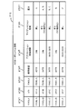
- FIG. 3 shows the data structure and data example of the host-volume information 212 used by the management server program 211.
- the host-volume information 212 holds information for each virtual volume.
- the attribute information includes a virtual volume number (VVOL # in the figure) 2121, an application program number (AP # in the figure) 2122, an assigned pool number (POOL number in the figure) 2123, a use size 2124, and an application program operation period 2125. , Volume migration function (migration function in the figure) 2126 and cost category 2127.
- a name, an identifier, identification information, and a number are information used to distinguish an object from other objects, and can be converted into each other.
- the virtual volume number can be called a virtual volume identifier or a virtual volume name.
- the configuration of each table is not limited to the illustrated example. For example, information necessary in this embodiment can be managed by linking a plurality of tables.
- the virtual volume number 2121 holds the identification name of the virtual volume.
- the application program number 2122 holds the identification name of the application program 443 that uses the virtual volume.
- the affiliation pool number 2123 holds the identification name of the pool to which the virtual volume belongs.
- the used size 2124 holds the size that is actually used among all the volume sizes of the virtual volume, in other words, the size to which pages in the pool are allocated.
- the application program operating period 2125 holds the operating period of the application program 443 that uses the virtual volume.
- the volume migration function 2126 indicates whether or not volume migration is possible on the host computer 40 that uses the virtual volume. If possible, it also indicates whether or not the application program 443 can be migrated. In the example of FIG. 3, “I / O non-stop” indicates that the virtual volume can be migrated while the application program 443 is running.
- the cost category 2127 indicates the cost category of the pool to which the virtual volume belongs.
- the cost category is an identification name.
- the cost classification is set to distinguish the grade of each logical volume constituting the pool or the department to which it belongs.
- ⁇ Grades are classified according to the price range of logical volumes, for example. For example, “A” indicates a volume in a high price range, “B” indicates a volume in a medium price range, and “C” indicates a volume in a low price range.
- the pool in which the cost category “A” is set is configured only from volumes in the high price range.
- the pool in which the cost classification “A, B” is set is configured with a high price range volume and / or a medium price range volume.
- a high price range volume can be called a high reliability volume
- a medium price range volume can be called a medium reliability volume
- a low price range volume can be called a low reliability volume.
- the high reliability volume is composed of a high reliability disk drive.
- the medium reliability volume is composed of medium reliability disk drives.
- the low reliability volume is composed of a low reliability disk drive.
- the department to which the organization belongs is used when the logical volumes that make up the pool are allocated by department. “A” is set for department A, “B” for department B, and “C” for department C. Cost partitioning is used to prevent changes in the nature or positioning of virtual volumes and pools.
- an important virtual volume to be associated with a pool composed of high-priced logical volumes is composed of low-priced logical volumes. Can be prevented from being transferred to the pool.
- the virtual volume used in the department A can be prevented from being migrated to a pool configured with the logical volume of the department B.
- Cost category 2144 may include a plurality of categories as described above. If multiple categories are set, it indicates that both are applicable.
- the host-volume information 212 includes information that can be acquired from the thin provisioning program 3143 in the storage 30, the application program 443 on the host computer 40, the volume migration program 442, and the like, and information input from the administrator. Can be created based on.
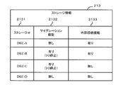
- FIG. 4 shows a data structure and data example of the storage information 213 used by the management server program 211.
- the storage information 213 holds information in units of storage 30.
- the attribute information includes a storage number (storage # in the figure) 2131, a volume migration function (migration function in the figure) 2132, and an access function to volumes in other storages (external connection function in the figure) 2133.
- the storage number 2131 holds the identification name of the storage 30.
- the volume migration function 2132 holds whether or not the storage 30 has a volume migration function. If it has a migration function, it also indicates whether or not migration is possible only when the application program 443 is stopped. For example, “I / O stop” in the example of FIG. 4 indicates that the volume can be migrated only when the application program 443 is stopped and no I / O request is generated.
- the storage information 213 can be created based on information that can be acquired from the input / output program 3141 and the volume migration program 3142 in the storage 30.
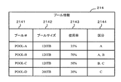
- FIG. 5 shows a data structure and data example of the pool information 214 used by the management server program 211.
- the pool information 214 holds information for each pool.
- the attribute information includes a pool number (pool # in the figure) 2141, a pool size 2142, a usage rate 2143, and a cost category 2144.
- the pool number 2141 holds a pool identification name.
- the pool size 2142 holds the total size of the pool, that is, the total size of real pages that can be allocated to the virtual volume.
- the usage rate 2143 indicates the ratio of the page size allocated to the virtual volume in the pool size 2142. When all pool sizes are assigned to virtual volumes, the usage rate is 100%.
- the cost category 2144 is assigned for the same purpose as the cost category 2127 in the host-volume information 212.
- the cost category 2144 is an identification name for distinguishing the logical volumes constituting the pool.
- the pool information 214 may be created based on the thin provisioning program 3143 in the storage 30 and information directly input from the administrator.
- FIG. 6 shows the data structure and data string of the unused volume information 215 used by the management server program 211.
- the unused volume information 215 holds information in unused volume units.
- the attribute information includes an unused volume number 2151, a storage number 2152, a size 2153, and a cost category 2154.
- the unused volume number 2151 holds the identification name of the unused volume.
- the storage number 2152 holds the identification name of the storage in which the unused volume exists.
- the size 2153 holds the storage size of the unused volume.
- the cost category 2154 holds an identification name indicating the cost category of the unused volume.
- the cost category 2154 may hold a plurality of identification names.
- the unused volume information 215 may be created based on the thin provisioning program 3143 in the storage 30, information that can be acquired from the disk controller 315, information that is directly input from the administrator, and the like.
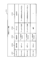
- FIG. 7 shows the data structure and data string of the management policy information 216 used by the management server program 211.
- the management policy information 216 holds information for each management policy.
- the management policy is information indicating a guideline for the management server program 211 to execute various management operations.
- the management policy indicates, for example, a response policy when the pool size is insufficient.
- the attributes of the management policy information 216 are a policy number 2161, an application target 2162, an activation condition 2163, an action 2164, and a success condition 2165.
- the policy number 2161 holds a policy identification name.
- the application target 2162 holds a policy application target. In the example of FIG. 7, “all pools” indicates that the same policy is applied to all pools. When the identification name of a specific pool is specified as an application target, the policy is applied only to the specified pool.
- the activation condition 2163 holds a condition that triggers execution of a specific action.
- the activation condition is defined as a condition regarding the pool usage rate.
- the action 2164 holds the type of action. Examples of action types include “pool size expansion” and “warning”. “Pool size expansion” means, for example, expanding the pool size when the pool size is insufficient. “Warning” means, for example, issuing a warning to the user when the pool size is likely to be insufficient.
- the success condition 2165 holds the condition that is the purpose of the action.
- the action success condition (purpose) is to keep the pool usage rate within a specific range.
- the management policy information 216 may have a configuration prepared in advance by the vendor of the management server program 211, or a configuration that can be manually created by an administrator.
- FIG. 8 is a flowchart showing a process for monitoring the capacity usage rate of the pool.
- step is abbreviated as S.
- the capacity usage rate of the pool is an index for measuring whether the pool size is excessive or insufficient, and the closer the value is to 100%, the more insufficient the size is.
- a threshold value for monitoring is set in advance, and some action is executed when the capacity usage rate of each pool exceeds the threshold value. The specific procedure is shown below.
- the subject of the operation will be described as a management computer. Since the following functions are realized by the microprocessor 22 reading and executing the management server program 211, the microprocessor 22 or the management server program 211 can also be described as an operation subject.
- the management computer 20 refers to the pool information 214 and selects the first pool (S8101).
- the management computer 20 determines whether or not the processing target pool has been selected (S8102). If there is no pool to be selected, the process ends (S8102: NO). If there is a pool to be selected, the following processing is executed.
- the management computer 20 acquires the capacity usage rate of the selected pool (S8103).
- the management computer 20 checks whether or not the capacity usage rate acquired in S8103 has exceeded the threshold defined in the management policy information 216 (S8104). In other words, it is determined whether or not the acquired capacity usage rate matches the activation condition 2163.
- the management computer 20 executes a process of expanding the pool size to cope with the capacity shortage (S8105). Details of the pool size expansion process will be described later with reference to FIG.
- the management computer 20 selects the next pool from the pool information 214 as a new processing target pool (S8106), and returns to S8102.
- S8106 a new processing target pool
- S8102 no selectable pools
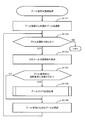
- FIG. 9 is a flowchart of processing for expanding the pool size in order to cope with the shortage of the pool size.
- the flowchart of FIG. 9 is executed in S8105 of FIG. In this process, the appropriateness of each countermeasure when the pool size is insufficient is evaluated in order, and the countermeasure that is evaluated as valid is executed.
- the processing target storage 30 is referred to as a self storage, and is distinguished from other storages other than the processing target storage.
- the management computer 20 determines whether or not the pool expansion is possible in the storage (self-storage) where the capacity is insufficient, and executes it if it is possible (S8201). Details of the process of expanding the pool size in the own storage will be described later with reference to FIG. When the pool capacity shortage is resolved by the execution of S8201 (S8202: YES), this process ends.
- the management computer 20 creates a list of other storages (other storage list) excluding its own storage based on the storage information 213 (S8203). ).
- the configuration may be such that information on other storage is acquired from the storage information 213. In that case, the local storage is not selected in S8204 and S8211.
- the management computer 20 selects one other storage described at the top of the other storage list (S8204). The management computer 20 determines whether another storage subject to processing has been selected (S8205). If another storage could not be selected (S8205: NO), the management computer 20 issues an alert indicating that a method for resolving the pool capacity shortage is not found (S8206), and ends this process.
- the management computer 20 checks the validity of the coping method of expanding the pool size by virtual volume migration, and executes the coping method if it is valid ( S8207).
- a method for expanding the pool size by moving the virtual volume will be described later with reference to FIG.
- S8208: YES As a result of processing S8207, when the pool capacity shortage is resolved, this processing ends (S8208: YES).
- the management computer 20 uses the other storage storage pool size.
- the validity of the coping method of extension of is checked, and if it is valid, the coping method is executed (S8209). Details of S8209 will be described later with reference to FIG.
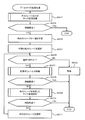
- FIG. 10 is a flowchart showing a process of expanding the pool size in the own storage, and is executed in S8201 of FIG.
- the validity of each unused volume in its own storage is evaluated as to whether it is appropriate as a pool size expansion volume in terms of its size, its cost, and its performance.
- An unused volume that is evaluated as valid is added to a pool of insufficient size, causing the pool to expand in size.
- the management computer 20 creates a list of unused volumes in its own storage (hereinafter also referred to as a candidate volume list for expansion) from the unused volume information 215 (S8301).
- the candidate volume list may be obtained from the unused volume information 215 instead of creating the candidate volume list separately from the unused volume information 215. In that case, in S8302 and S8307, only an unused volume in the own storage is selected.
- the management computer 20 selects the first unused volume from the candidate volume list (S8302). If there is no selectable unused volume (S8303: NO), the process is terminated as the countermeasure is incomplete. If no selectable unused volume is found (S8303: NO), a process (S8600) described later with reference to FIG. 13 may be performed.
- the management computer 20 determines whether or not the size of the unused volume is a predetermined size (S8304).
- the predetermined size is, for example, a size necessary for solving the shortage of the pool size.
- the predetermined size means a size necessary to satisfy the success condition 2165 of the management policy. Thus, whether or not the size of the unused volume matches the purpose can be determined based on the contents of the management policy list 216.
- a policy with a startup condition 2163 of “pool usage rate 70 to 84%” is applied.
- the content of the success condition 2165 regarding the action of the policy is defined as “reducing the pool usage rate to a range of 40-60%”.
- the reason why the lower limit of the usage rate of “40%” is set is to prevent excessive measures. From the current pool size and capacity usage rate, the additional size required to obtain the target capacity usage rate is obtained by the following equation (1).
- an additional size in the range of 25 TB to 87.5 TB is required. If the size of the selected unused volume is within the above range, it can be determined that pool expansion using that volume is appropriate.
- the management computer 20 selects the next unused volume from the candidate volume list (S8307), and proceeds to S8303.
- the management computer 20 evaluates the validity of the cost category of the unused volume (S8305). In the figure, for convenience, the “cost category” is simply expressed as “cost”.
- the content of the cost category set for the selected unused volume (the content of the cost category 2154 of the unused volume information 215) is set in the allocation destination pool. It is determined whether or not it is included in the content of the cost category (the content of the cost category 2144 of the pool information 214).
- “A” is set as the cost category 2154 for the unused volume having the identification name “UVOL-A”.
- “A, B” is set as the cost category 2144 in the pool having the identification name “POOL-B”.
- the cost category of the pool matches the cost category of the unused volume. To do.
- the management computer 20 predicts and evaluates the performance after the pool size is expanded (8306). When the selected unused volume is added to the pool, the management computer 20 determines whether or not the pool can maintain performance of a predetermined value or higher.
- the average response performance of the pool decreases.
- the I / O performance of the virtual volume that uses the pages in the pool also decreases.
- the unused volume to be added may be limited to a logical volume having the same or better performance than the currently used logical volume.
- the degree of performance degradation of the virtual volume may be estimated, and if the degree is within the allowable range, the selected unused volume may be added to the pool.
- the management computer 20 When it is predicted that no performance problem will occur after the volume is added (S8306: YES), the management computer 20 causes the selected unused volume to be expanded (S8308), and the process is terminated. To do.
- the management computer 20 selects the next unused volume from the candidate volume list. (S8307) and the process returns to S8303.
- FIG. 10 describes a case where a shortage of the capacity of the pool can be dealt with by simply adding one unused volume to the pool.
- the present invention is not limited to the configuration in which one unused volume is added, and a configuration in which a plurality of unused volumes are added to the pool to solve the pool capacity shortage may be employed.
- the size check in S8304 it is determined that the size of the unused volume matches the additional purpose except when the size exceeds the upper limit. Then, a list of unused volumes that pass each check of S8305 and S8306 is created, and a plurality of unused volumes whose total size is a predetermined size are extracted from the list, and the plurality of unused volumes are stored in the pool. A configuration may be added.
- a configuration may be adopted in which one unused volume determined to be less than the predetermined size in S8304 is added to the pool.
- a plurality of countermeasures FIGS. 11 and 12 are used together in addition to the countermeasure shown in FIG.
- the usage rate of the pool can be lowered as compared with the case where no unused volume is added. Therefore, even if an unused volume that is less than the predetermined size is added to the pool, the risk of the pool size being depleted can be reduced.
- Such a countermeasure is shown as S8600 in FIG. With reference to FIG. 13, a coping method using another pool in the own storage will be described.
- the management computer 20 creates a list of each logical volume constituting the other pool for one or a plurality of other pools existing in its own storage (S8601). ).
- the management computer 20 selects the first volume from the list of volumes constituting the other pool (S8602). The management computer 20 determines whether or not the selected volume can be diverted to the processing target pool (the own pool whose capacity is insufficient) (S8603).
- the capacity usage rate of the other pool can be equal to or less than a predetermined criterion. This standard is provided in order to prevent the pool of the diversion source from running out of capacity due to the diversion of the logical volume.
- the management computer 20 makes each determination similar to that described in FIG.
- the management computer 20 determines whether or not the logical volume has a predetermined size (S8604).
- the management computer 20 determines whether or not the cost category of the logical volume matches the cost category of the diversion destination pool (own pool) (S8605).
- the management computer 20 predicts whether or not the own pool has a performance equal to or higher than a predetermined value (S8606).
- the management computer 20 can take into consideration that if the logical volume is removed from the other pool, the performance of the other pool may be degraded, and that it takes time to remove the logical volume (S8607).
- any one logical volume may be selected.
- the management computer 20 selects the next volume (S8608) and returns to S8603. When all the determination steps are satisfied, the management computer 20 removes the logical volume in the other pool from the other pool and adds it to the own pool in the capacity shortage state (S8609). Returning to FIG.
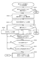
- FIG. 11 is a flowchart showing a process of resolving the pool capacity shortage by moving the virtual volume, and is executed in S8207 of FIG.
- each virtual volume using a pool with insufficient capacity is evaluated in terms of the presence / absence of migration means, volume size, suitability of cost classification, migration completion time, and performance after migration.
- a virtual volume for which it is determined that the movement of another storage to another pool is appropriate is moved to another pool in the other storage. The specific procedure is shown below.
- the management computer 20 creates a list of virtual volumes using a pool with insufficient capacity (S8401). Since the list of virtual volumes indicates a list of virtual volumes that are migration candidates, in the following description, it is referred to as a migration candidate virtual volume list.
- the migration candidate virtual volume list may be created from the virtual volume information 212.
- the migration candidate virtual volume list can be obtained from the virtual volume information 212 instead of being created separately from the virtual volume information 212. In that case, in S8402 and S8409, a virtual volume belonging to a pool with insufficient capacity is selected.
- the management computer 20 selects the first virtual volume from the migration candidate virtual volume list (S8402). If the virtual volume could not be selected (S8403: NO), this process ends as a countermeasure incomplete.
- the management computer 20 checks whether there is a means for moving the virtual volume to the selected other storage 30 (S8404). There are means for moving the virtual volume on the storage 30 side and means for moving the virtual volume on the host computer 40 side.
- Whether or not the storage 30 has means for moving the virtual volume can be determined from the contents of the volume migration function 2132 of the storage information 213. Whether or not the host computer 40 has a means for moving a virtual volume can be determined by the contents of the volume migration function 2126 of the virtual volume information 212.
- the management computer 20 confirms the presence / absence of virtual volume migration means on the storage side and the presence / absence of virtual volume migration means on the host computer side, and has at least one means for migrating the virtual volume to another storage It is determined whether or not to perform (S8404).
- the management computer 20 selects the next virtual volume (S8409) and returns to S8403.
- the management computer 20 determines whether the size of the virtual volume is a predetermined size (S8405). Whether or not the size of the virtual volume matches the purpose of the management policy can be determined based on the contents of the management policy list 216.
- a policy with a startup condition 2163 of “pool usage rate 70 to 84%” is applied.
- the content of the success condition 2165 regarding the action of the policy is defined as “reducing the pool usage rate to a range of 40-60%”. From the current pool size and capacity usage rate, the virtual volume migration size necessary to obtain the target capacity usage rate is obtained by the following equation (2).
- the management computer 20 matches the cost category set for the virtual volume with the cost category set for the other pool of the migration destination. It is determined whether or not (S8406).
- the cost category 2154 of the virtual volume information 212 when the content of the cost category 2154 of the virtual volume information 212 is included in the content of the cost category 2144 of the pool information 214, it can be determined that both cost categories are suitable. For example, a case will be described in which it is evaluated that a virtual volume having an identification name “VVOL-B” shown in FIG. 3 is moved to a pool having an identification name “POOL-A” shown in FIG. As shown in FIG. 3, the cost category 2154 of the virtual volume (VVOL-B) is “A, B”. As shown in FIG. 5, “A” is set in the cost category 2144 of the pool (POOL-A).
- the management computer 20 determines that both cost categories are suitable. If it is determined that the cost category of the virtual volume and the cost category of the migration destination pool do not match, the process advances to step S8409.
- the pool size depletion date and time may be calculated based on, for example, an increase rate per unit time obtained from the past history of the pool capacity usage rate.
- the migration completion date / time is, for example, (a) whether the virtual volume can be migrated while the application program 443 is in operation, (b) the operation period of the application program 443, (c) processing time required for migration of the virtual volume, etc. It may be calculated based on the information.
- (A) can confirm the volume migration program 442 in the host computer 40 by referring to the volume migration function 2126 of the virtual volume information 212.
- the volume migration program 3142 in the storage 30 it can be confirmed by referring to the volume migration function 2132 of the storage information 213.
- (B) can be confirmed by referring to the application program operating period 2125 of the virtual volume information 212.
- (C) is obtained by multiplying the size of the virtual volume by the virtual volume migration time per size.
- the virtual volume migration time per size can be calculated, for example, based on a reference value set in advance, or can be selected from the time taken to migrate the past virtual volume. A reference value is prepared for each performance of each logical volume.
- the method for calculating the movement completion date / time differs depending on the contents of (a). In other words, if the virtual volume can be moved without stopping the application program 443, the current time is the time required for the migration required in (c).
- the migration of the virtual volume may not be completed by the business start time. In order to prevent such a situation from occurring, for example, when the virtual volume cannot be moved while the application program 443 of FIG. If it is after the start time of the program 443, it may be determined that the virtual volume cannot be migrated.
- the pool size depletion date and time and the virtual volume migration completion date and time are both estimated values, so it is preferable to judge with sufficient margin.
- the pool size depletion date and time is, for example, a time earlier than the predicted value by a certain amount.
- the transition completion date and time is a time later than the predicted value by a certain amount.
- the response is relatively urgent.
- it may be configured to always select a countermeasure (for example, pool expansion) with a relatively short processing time until the countermeasure is completed.
- both the virtual volume migration by the volume migration program 442 in the host computer 40 and the virtual volume migration by the volume migration program 3142 in the storage 30 can be performed, one of them is selected by some method. There is a need to.
- the selection criteria may include, for example, the speed of time until processing is completed, the load on the host computer 40, the load on the storage 30, and the like. As shown in FIG. 14, when the volume migration program 442 of the host computer 40 is used, there is an effect that the data transfer size can be relatively reduced and unnecessary data may be removed.
- the file system manages n pieces of data D1, D2, D3 of size SZ1.
- the used size on the file system is SZ1 ⁇ n.
- These data D1, D2, and D3 are written to the virtual volume 720 in a discrete manner.
- n chunks (real pages) C1, C2, and C3 are allocated to store the data D1, D2, and D3.
- the chunk size is SZ2 (SZ2> SZ1). Therefore, the page allocation size to the virtual volume 720 is SZ2 ⁇ n.
- the data transfer amount when the host computer 40 moves the virtual volume is SZ1 ⁇ n
- the data transfer amount when the storage 30 moves the virtual volume is SZ2 ⁇ n, the latter being larger.
- the time required for migration becomes longer than when the host computer 40 moves a virtual volume.
- the difference between the used size (SZ1 ⁇ n) on the file system and the page allocation size (SZ2 ⁇ n) to the virtual volume may be used as a reference for selecting the volume migration means.
- the volume migration program 442 in the host computer 40 has a mechanism for migrating data excluding deleted data.
- the deleted unnecessary data is not stored in the migration destination pool 721. . Therefore, the used size of the pool can be reduced compared to before the migration of the virtual volume.
- the volume migration program 442 in the host computer 40 is preferentially executed. You may do it.
- the management computer 20 predicts and evaluates the performance of the virtual volume after the virtual volume migration (S8408). That is, the management computer 20 determines whether or not the performance of the virtual volume can be maintained even after the migration.
- ⁇ Migrating a virtual volume from a pool in its own storage to a pool in another storage may reduce the I / O performance of the virtual volume. Whether or not the I / O performance of the virtual volume decreases after migration is determined for each of the migration source pool and the migration destination pool, the performance of the logical volumes that make up the pool, the number of logical volumes, the size of the pool load, The determination may be made in consideration of the I / O amount of the migration target virtual volume. If the degree of performance degradation of the virtual volume is within the allowable range, the migration may be recognized as having no particular problem.
- the selected virtual volume is migrated to the selected other storage 30 (S8410), and the process is terminated as the countermeasure is complete.
- the flowchart in FIG. 11 shows a case where the capacity of the migration source pool is expanded only by migrating one virtual volume, but the present invention is not limited to this, and a configuration in which a plurality of virtual volumes are migrated may be used.
- the volume size check in S8405 it is determined that the purpose is to solve the pool capacity shortage except when the virtual volume size is over.
- a list of a plurality of virtual volumes that pass each determination of S8404, S8406, and S8407 is created, and a plurality of virtual volumes are extracted from the list so that the total size of the virtual volumes falls within the required size range. Migrate a plurality of extracted virtual volumes to a plurality of other pools.
- a method of migrating a virtual volume from a pool with insufficient capacity to a pool with sufficient free capacity can be included in the options.
- the size of the virtual volume matches the purpose, or the cost category of the migration destination pool and the cost category of the virtual volume match Whether the pool with insufficient capacity can wait until the migration completion time or whether the performance after the migration is maintained may be evaluated.
- FIG. 12 is a flowchart of a process for expanding the size of the own storage pool using the logical volume of other storage, and is executed in S8209 of FIG. In this process, as described below, it is checked whether or not it is possible to connect to the selected other storage volume (external volume) from its own storage. If connection is possible, the validity of whether the unused volume among the selected volumes in the other storage is appropriate as a volume for pool expansion in terms of volume size, cost category, and performance change To evaluate. If there is an unused external volume that is evaluated as valid, the local storage is connected to the unused external volume, the external volume is allocated to a pool in the local storage, and the pool size is expanded.
- the management computer 20 checks whether or not its own storage has a function (external connection function) for connecting to the volume of the selected other storage (S8501). For this check, the external connection function 2133 of the storage information 213 may be referred to.
- the management computer 20 creates an unused volume list (hereinafter, candidate volume list) in the selected other storage from the unused volume information 215 (S8502).
- candidate volume list an unused volume list
- the configuration may be such that information on unused candidate volumes is read from the unused volume information 215. In that case, in S8503 and S8508, only the unused volume in the selected other storage is selected.
- the management computer 20 selects one leading unused volume from the candidate volume list (S8503).
- the management computer 20 determines whether an unused volume has been selected (S8504). If there is no unused volume that can be selected (S8504: NO), the processing is terminated as the countermeasure is incomplete.
- the management computer 20 determines whether or not the size of the unused volume is a predetermined size (S8505). That is, it is confirmed whether the selected unused volume has an appropriate size for solving the shortage of the capacity of the pool in the own storage. Whether or not the size of the unused volume is a predetermined size may be determined based on the contents of the management policy list 216. The processing content is the same as S8304 in FIG. More specifically, the management computer 20 determines whether or not the size of the unused volume is in a range necessary for achieving the purpose.
- the management computer 20 selects the next unused volume from the candidate volume list (S8508), and returns to S8504.
- the management computer 20 determines whether the cost category of the unused volume matches the cost category of the allocation destination pool (S8506). ).
- the specific processing content is the same as S8305 in FIG.
- the management computer 20 evaluates the performance when the unused volume is added to the pool (S8507).
- the performance evaluation method is the same as S8306 in FIG.
- a change in the performance value of the pool is predicted in consideration of overhead.
- the pool performance can be predicted using the amount of overhead set as a fixed value in advance.
- the input / output processing program 3141 of the storage 30 may be provided with a function for measuring the overhead amount, and the pool performance may be predicted based on the measured value.
- the pool size is expanded using the selected unused volume (S8509). ). This process ends as the countermeasure is completed. If it is predicted that the performance of the pool will decrease by more than the allowable value (S8507: NO), the process moves to S8508.
- the size check in S8505 it is determined that the volume is suitable for the purpose except when the volume size exceeds a predetermined size (predetermined size range). Further, a list of unused volumes that pass each check of S8506 and S8507 is created, and a plurality of unused volumes that have a total size of unused volumes within the required size range are extracted from the list.
- the pool size can also be expanded by adding a plurality of extracted unused volumes to the pool.
- the pool size may be expanded using an unused volume that does not reach the predetermined size. In that case, multiple countermeasures will be implemented. Even when an unused volume for realizing the target capacity usage rate cannot be obtained, the capacity usage rate of the pool can be lowered as compared with the case where no unused volume is added to the pool. Therefore, even if an unused volume of insufficient size is added to the pool, the risk of the pool capacity being depleted can be reduced.
Landscapes
- Engineering & Computer Science (AREA)
- Theoretical Computer Science (AREA)
- Human Computer Interaction (AREA)
- Physics & Mathematics (AREA)
- General Engineering & Computer Science (AREA)
- General Physics & Mathematics (AREA)
- Information Retrieval, Db Structures And Fs Structures Therefor (AREA)
Priority Applications (1)
| Application Number | Priority Date | Filing Date | Title |
|---|---|---|---|
| US13/054,759 US8543786B2 (en) | 2010-09-29 | 2010-10-28 | Computer system and computer system management method for adding an unused real volume to a pool |
Applications Claiming Priority (2)
| Application Number | Priority Date | Filing Date | Title |
|---|---|---|---|
| JP2010218242A JP5602564B2 (ja) | 2010-09-29 | 2010-09-29 | 計算機システム及び計算機システムの管理方法 |
| JP2010-218242 | 2010-09-29 |
Publications (1)
| Publication Number | Publication Date |
|---|---|
| WO2012042678A1 true WO2012042678A1 (ja) | 2012-04-05 |
Family
ID=45892181
Family Applications (1)
| Application Number | Title | Priority Date | Filing Date |
|---|---|---|---|
| PCT/JP2010/069222 Ceased WO2012042678A1 (ja) | 2010-09-29 | 2010-10-28 | 計算機システム及び計算機システムの管理方法 |
Country Status (2)
| Country | Link |
|---|---|
| JP (1) | JP5602564B2 (enExample) |
| WO (1) | WO2012042678A1 (enExample) |
Cited By (1)
| Publication number | Priority date | Publication date | Assignee | Title |
|---|---|---|---|---|
| WO2014041591A1 (ja) * | 2012-09-11 | 2014-03-20 | 株式会社日立製作所 | 管理装置及び管理方法 |
Families Citing this family (4)
| Publication number | Priority date | Publication date | Assignee | Title |
|---|---|---|---|---|
| WO2016129053A1 (ja) * | 2015-02-10 | 2016-08-18 | 株式会社日立製作所 | ストレージ装置の管理計算機 |
| WO2017163322A1 (ja) * | 2016-03-23 | 2017-09-28 | 株式会社日立製作所 | 管理計算機、および計算機システムの管理方法 |
| JP6851350B2 (ja) * | 2018-08-30 | 2021-03-31 | 株式会社日立製作所 | ストレージシステム及び記憶制御方法 |
| JP6853227B2 (ja) | 2018-10-10 | 2021-03-31 | 株式会社日立製作所 | ストレージシステム及びストレージ制御方法 |
Citations (2)
| Publication number | Priority date | Publication date | Assignee | Title |
|---|---|---|---|---|
| JP2005275829A (ja) * | 2004-03-25 | 2005-10-06 | Hitachi Ltd | ストレージシステム |
| JP2010086424A (ja) * | 2008-10-01 | 2010-04-15 | Hitachi Ltd | ストレージ装置の管理装置 |
Family Cites Families (5)
| Publication number | Priority date | Publication date | Assignee | Title |
|---|---|---|---|---|
| JP4890033B2 (ja) * | 2006-01-19 | 2012-03-07 | 株式会社日立製作所 | 記憶装置システム及び記憶制御方法 |
| JP2010079626A (ja) * | 2008-09-26 | 2010-04-08 | Hitachi Ltd | 計算機システムの負荷分散方法及びシステム |
| JP4809413B2 (ja) * | 2008-10-08 | 2011-11-09 | 株式会社日立製作所 | ストレージシステム |
| JP2010170411A (ja) * | 2009-01-23 | 2010-08-05 | Hitachi Ltd | 計算機システム、ストレージプール管理方法 |
| JP5235154B2 (ja) * | 2009-03-31 | 2013-07-10 | 富士通株式会社 | 管理装置および管理プログラム |
-
2010
- 2010-09-29 JP JP2010218242A patent/JP5602564B2/ja not_active Expired - Fee Related
- 2010-10-28 WO PCT/JP2010/069222 patent/WO2012042678A1/ja not_active Ceased
Patent Citations (2)
| Publication number | Priority date | Publication date | Assignee | Title |
|---|---|---|---|---|
| JP2005275829A (ja) * | 2004-03-25 | 2005-10-06 | Hitachi Ltd | ストレージシステム |
| JP2010086424A (ja) * | 2008-10-01 | 2010-04-15 | Hitachi Ltd | ストレージ装置の管理装置 |
Cited By (3)
| Publication number | Priority date | Publication date | Assignee | Title |
|---|---|---|---|---|
| WO2014041591A1 (ja) * | 2012-09-11 | 2014-03-20 | 株式会社日立製作所 | 管理装置及び管理方法 |
| US9043571B2 (en) | 2012-09-11 | 2015-05-26 | Hitachi, Ltd. | Management apparatus and management method |
| JPWO2014041591A1 (ja) * | 2012-09-11 | 2016-08-12 | 株式会社日立製作所 | 管理装置及び管理方法 |
Also Published As
| Publication number | Publication date |
|---|---|
| JP2012073825A (ja) | 2012-04-12 |
| JP5602564B2 (ja) | 2014-10-08 |
Similar Documents
| Publication | Publication Date | Title |
|---|---|---|
| US8543786B2 (en) | Computer system and computer system management method for adding an unused real volume to a pool | |
| JP4749255B2 (ja) | 複数種類の記憶デバイスを備えたストレージシステムの制御装置 | |
| JP5451875B2 (ja) | 計算機システム及びその記憶制御方法 | |
| US6725328B2 (en) | Automated on-line capacity expansion method for storage device | |
| JP5186367B2 (ja) | メモリ・マイグレーションのシステムおよび方法 | |
| CN103250143B (zh) | 数据存储方法和存储设备 | |
| JP5134915B2 (ja) | 記憶領域の構成最適化方法、計算機システム及び管理計算機 | |
| US8694727B2 (en) | First storage control apparatus and storage system management method | |
| US8924659B2 (en) | Performance improvement in flash memory accesses | |
| JP5081498B2 (ja) | 計算機システム、および、その制御方法 | |
| US20100082900A1 (en) | Management device for storage device | |
| JP5149556B2 (ja) | システム情報要素を移行するストレージシステム | |
| US8904121B2 (en) | Computer system and storage management method | |
| US20150378604A1 (en) | Computer system and control method for computer system | |
| US8560801B1 (en) | Tiering aware data defragmentation | |
| JP5602564B2 (ja) | 計算機システム及び計算機システムの管理方法 | |
| US9983806B2 (en) | Storage controlling apparatus, information processing apparatus, and computer-readable recording medium having stored therein storage controlling program | |
| WO2015198441A1 (ja) | 計算機システム、管理計算機、および管理方法 | |
| US8572347B2 (en) | Storage apparatus and method of controlling storage apparatus | |
| WO2015001620A1 (ja) | ストレージシステム、記憶制御方法、及び計算機システム | |
| JP2008299559A (ja) | ストレージシステム及びストレージシステムにおけるデータ移行方法 | |
| US9740420B2 (en) | Storage system and data management method | |
| JP2007122268A (ja) | 計算機システム、記憶領域割当方法及び管理計算機 | |
| US11550489B2 (en) | Storage system and processing migration method | |
| WO2016006072A1 (ja) | 管理計算機およびストレージシステム |
Legal Events
| Date | Code | Title | Description |
|---|---|---|---|
| WWE | Wipo information: entry into national phase |
Ref document number: 13054759 Country of ref document: US |
|
| 121 | Ep: the epo has been informed by wipo that ep was designated in this application |
Ref document number: 10857891 Country of ref document: EP Kind code of ref document: A1 |
|
| NENP | Non-entry into the national phase |
Ref country code: DE |
|
| 122 | Ep: pct application non-entry in european phase |
Ref document number: 10857891 Country of ref document: EP Kind code of ref document: A1 |