WO2012036056A1 - 立体画像表示装置、立体画像表示方法、立体画像表示方法をコンピュータに実行させるためのプログラム、及びそのプログラムを記録した記録媒体 - Google Patents
立体画像表示装置、立体画像表示方法、立体画像表示方法をコンピュータに実行させるためのプログラム、及びそのプログラムを記録した記録媒体 Download PDFInfo
- Publication number
- WO2012036056A1 WO2012036056A1 PCT/JP2011/070441 JP2011070441W WO2012036056A1 WO 2012036056 A1 WO2012036056 A1 WO 2012036056A1 JP 2011070441 W JP2011070441 W JP 2011070441W WO 2012036056 A1 WO2012036056 A1 WO 2012036056A1
- Authority
- WO
- WIPO (PCT)
- Prior art keywords
- image
- parallax
- eye
- adjustment
- stereoscopic
- Prior art date
- Legal status (The legal status is an assumption and is not a legal conclusion. Google has not performed a legal analysis and makes no representation as to the accuracy of the status listed.)
- Ceased
Links
Images




Classifications
-
- H—ELECTRICITY
- H04—ELECTRIC COMMUNICATION TECHNIQUE
- H04N—PICTORIAL COMMUNICATION, e.g. TELEVISION
- H04N13/00—Stereoscopic video systems; Multi-view video systems; Details thereof
- H04N13/30—Image reproducers
- H04N13/398—Synchronisation thereof; Control thereof
-
- H—ELECTRICITY
- H04—ELECTRIC COMMUNICATION TECHNIQUE
- H04N—PICTORIAL COMMUNICATION, e.g. TELEVISION
- H04N13/00—Stereoscopic video systems; Multi-view video systems; Details thereof
- H04N13/10—Processing, recording or transmission of stereoscopic or multi-view image signals
- H04N13/106—Processing image signals
- H04N13/128—Adjusting depth or disparity
Definitions
- the present invention relates to an apparatus for displaying a stereoscopic image, and more particularly to a display method for adjusting the stereoscopic effect of a stereoscopic image, a stereoscopic image display program, and a computer-readable recording medium on which the recording method is recorded.
- stereoscopic images Humans have the ability to grasp the space from the difference in images obtained by two eyes with a fixed interval.
- the shift of the corresponding points in the image obtained from different viewpoints by the left and right eyes is called parallax, and the positional relationship of the target is grasped three-dimensionally using parallax as one of the cues.
- a means for displaying a right eye image and a left eye image on the right eye is provided, and stereoscopic images can be displayed by presenting parallax images as the right eye image and the left eye image. It is known to be possible.
- a plurality of images provided with parallax for the purpose of stereoscopic viewing are referred to as stereoscopic images.
- extreme parallax also causes an unnatural positional relationship on the short distance side, and an extreme crossing is forced on the viewer, making it impossible to perform comfortable stereoscopic viewing.
- stereoscopic viewing can be comfortably performed within a certain range of the parallax amount of the stereoscopic image.
- the parallax amount is large, the images of both eyes are not fused and stereoscopic viewing is impossible.
- the parallax is adjusted by shifting the display position of the left and right images to the left and right so that the stereoscopic image can be easily viewed.
- the method is shown in Patent Document 1 below.
- Patent Document 2 a method of creating an interpolation image with a small parallax and displaying the parallax gradually when displaying two stereoscopic images in succession is disclosed in Patent Document 2 below.
- parallax adjustment is performed by shifting the display positions of the left and right images, and the depth position of the displayed object is moved back and forth as a whole, so that the displayed objects can be easily fused. it can.
- the display position is shifted to the left or right with the left and right images displayed, the display position in the depth direction of the displayed image will change, and stereoscopic viewing will not be possible at the moment of changing the parallax amount, or even if it can be displayed causess the viewer to feel a sudden movement in the front-rear direction, creating a sense of incongruity.
- An object of the present invention is to provide a stereoscopic image display device, a stereoscopic image display method, and a stereoscopic image display method that achieve comfortable stereoscopic viewing while avoiding an uncomfortable feeling and 3D sickness of an observer with respect to image position fluctuation in the depth direction when adjusting parallax.
- a program for causing a computer to execute the method and a recording medium recording the program are provided.
- a stereoscopic image including a right-eye image and a left-eye image is displayed, and stereoscopic viewing is possible by presenting the right-eye image to the right eye and the left-eye image to the left eye
- a parallax adjustment unit that adjusts parallax by applying processing based on the parallax amount adjustment information to at least one of the right-eye image and the left-eye image that constitutes data, and the stereoscopic image data
- the right-eye image and the left-eye image are presented to the right eye and the left eye, respectively, and a display unit that displays a stereoscopic image and the parallax adjustment unit are based on the parallax amount adjustment information input from the input unit.
- an image conversion processing unit that displays a different image from the image whose current amount of parallax is being adjusted between the display screen before adjustment and the display screen after adjustment.
- a stereoscopic image display device characterized by this is provided. Thereby, a depth position can be adjusted without a sense of incongruity.
- the other image may be displayed so as to cover part of the image.
- the image conversion processing unit preferably displays a uniform image without a pattern as the another image. In this way, it can be realized with simple hardware.
- the image conversion processing unit preferably displays an image having a uniform parallax as the another image.
- the convergence angle of the observer during the image conversion can be set to an intended angle.
- the image conversion processing unit displays an image having a parallax value between the parallax of the image before adjustment and the parallax of the image after adjustment as the other image.
- parallax can be changed smoothly.
- the image conversion processing unit displays a plurality of images whose parallax is continuously changed as the another image.
- the vergence angle of the observer during image conversion can be controlled intentionally.
- the portion where the parallax is changed is a part of the screen. Thereby, 3D sickness can be avoided.
- a part where the parallax is changed among the other images including a plurality of images whose parallax is continuously changed is determined based on a characteristic part of the stereoscopic image data.
- the another image composed of a plurality of images whose parallax is continuously changed is preferably selected so that the parallax is continuously changed from the parallax of the image before adjustment to the parallax of the image after adjustment. . Thereby, parallax can be changed smoothly.
- the time for displaying the another image is preferably 0.3 seconds or more. This can prevent video sickness.
- Crossfade processing is performed on at least one of the display screen at the time of switching from the display screen before the adjustment to the other image and the conversion from the other image to the image after the adjustment.
- preferable Thereby, it is possible to weaken the stimulation of the image and reduce fatigue.
- a stereoscopic image including a right-eye image and a left-eye image is displayed, and the stereoscopic image is displayed by presenting the right-eye image to the right eye and the left-eye image to the left eye.
- a method for displaying a stereoscopic image the step of inputting parallax amount adjustment information for changing a parallax amount of stereoscopic image data composed of a right-eye image and a left-eye image, and the stereoscopic image
- the current parallax amount is different between the display screen before the adjustment and the display screen after the adjustment.
- a stereoscopic image display method comprising the step of displaying another image.
- the step of displaying another image different from the image whose parallax amount is currently being adjusted may cover a part of the image.
- the present invention may be a program for causing a computer to execute the stereoscopic image display method described above, or a computer-readable recording medium for recording the program.
- the parallax when adjusting the parallax, it is possible to avoid a sense of incongruity and 3D sickness associated with changing the parallax and realize a comfortable stereoscopic view.
- FIG. 1 is a block diagram illustrating a configuration example of the stereoscopic image display apparatus according to the present embodiment.
- the stereoscopic image display apparatus A processes the input image data with the input unit 10 and generates display data that can be stereoscopically displayed (hereinafter, stereoscopic image data).
- a stereoscopic image processing unit 100 that performs image processing for performing image processing, a parallax adjustment unit 101 that adjusts parallax of the image, a display control unit 102 that controls display by matching an image with the display unit, and a display unit 103 that displays an image
- the system control unit 104 controls the entire system, the user input unit 105 that the user inputs, and the glasses synchronization unit 106 that synchronizes the shutter glasses, and uses the shutter glasses 107 that the user wears separately.
- FIG. 2 is a diagram illustrating a configuration example of the parallax adjustment unit 101.
- the parallax adjustment unit 101 includes a left-eye image shift processing unit 1011 and a right-eye pixel shift processing unit 1012, a left-eye image conversion processing unit 1013, and a right-eye image conversion processing unit 1014, The conversion image recording unit 1015 and the communication / control unit 1016 are included. Next, the operation of each component will be described.
- the image data input via the input unit 10 is expanded into left-eye image data and right-eye image data in the stereoscopic image processing unit 100 according to the input format.
- the additional information is extracted and transmitted to the system control unit 104.
- the input image data may be any data such as data based on broadcast waves, data read electronically from a recording medium, or data transmitted from a network.
- the right-eye image data and the left-eye image data may be created from a single piece of image data. That is, it may be a multi-viewpoint image synthesized from image data and depth data, or a multi-viewpoint image created by estimating depth information.
- the developed left-eye image data and right-eye image data are sent to the parallax adjustment unit 101 to adjust parallax.
- a communication / control unit 1016 communicating with the system control unit 104 controls each component.
- the left-eye image shift processing unit 1011 and the right-eye image shift processing unit 1012 receive an instruction (parallax amount adjustment information) from the system control unit 104 via the communication / control unit 1016, and receive the left-eye image and the right-eye image. Each is shifted left and right to adjust the parallax.
- the left and right eye image data whose parallax has been adjusted are input to the left eye image conversion processing unit 1013 and the right eye 1014, respectively.
- Image data from the converted image recording unit 1015 can be input to the left-eye image conversion processing unit 1013 and the right-eye image conversion processing unit 1014, and an instruction from the system control unit 104 is received via the communication / control unit 1016. In response, the image is converted between the input left and right eye image and another image to be a converted image.
- the left-eye image and right-eye image whose parallax has been adjusted are sent to the display control unit 102.
- the display control unit 102 performs display control in accordance with the display unit 103 and sends a signal to the glasses synchronization unit 106.
- the glasses synchronization unit 106 sends a synchronization signal to the shutter glasses 107 worn by the user, and synchronization processing with the display unit 103 is performed. More specifically, for example, a liquid crystal display panel is used for the display unit 103 to alternately display a left-eye image and a right-eye image, and perform stereoscopic viewing in synchronization with the shutter glasses 107 worn by the observer.
- the display control unit 102 outputs the left-eye image and the right-eye image to the display unit 103 alternately.
- the output frequency is, for example, 120 images for the left eye and for the right eye, each per second.
- the display unit 103 displays the image sent from the display control unit 102 at any time.
- the left-eye image is displayed on the display unit 103
- the left-eye shutter of the shutter glasses 107 is opened and the right-eye shutter is closed.
- the left-eye image is displayed on the left eye, and when the right-eye image is displayed, the left-eye shutter is closed, and the right-eye shutter is opened to display the right-eye image on the right eye.
- the observer uses the user input unit 105 to input parallax amount adjustment data for the screen to be displayed.
- the user input unit 105 can be realized by a remote controller, for example, but can be realized by various means such as a keyboard, a mouse, a touch panel, and a dial, and may be gesture recognition regardless of the format.
- the parallax amount adjustment data input from the user input unit 105 is transmitted to the parallax adjustment unit 101 via the system control unit 104.
- the parallax adjustment unit 101 performs parallax adjustment processing based on the received parallax amount adjustment data. If the parallax amount adjustment data is data indicating no parallax adjustment, the parallax adjustment unit 101 outputs the left and right eye image data as it is without performing the parallax adjustment processing.
- FIG. 3 is a top view of the viewer and the display.
- FIG. 3A shows a normal two-dimensional display state, in which a corresponding point between the right-eye image and the left-eye image is at the same position on the display (display surface) when a stereoscopic image is displayed. In this case, this corresponding point is perceived as being on the display.
- FIG. 3B shows a state where the corresponding points P 2 and P 3 between the right-eye image and the left-eye image are shifted to the right on the display and the left-eye image to the left on the display. In this state, the observer perceives this point behind the display surface (P 4 ).
- FIG. 3C shows a state where the corresponding points P 5 and P 6 of the right-eye image and the left-eye image are shifted to the left on the display and the left-eye image to the right on the display. In this state, the observer perceives this point in front of the display surface (P 7 ).
- FIG. 3D is a diagram summarizing these.
- the corresponding point between the right eye image and the left eye image is displayed with the right eye image shifted to the right and the left eye image shifted to the left, and the distance between the corresponding points is equal to the binocular distance, this point is Although it is perceived at infinity, if the distance between corresponding points exceeds the distance between both eyes, the line of sight does not become a divergent direction and cannot be fused.
- the corresponding points of the right-eye image and the left-eye image on the display are greatly shifted to the left for the right-eye image and to the right for the left-eye image (P 8 , P 9 )
- the line of sight is extremely crossed. It becomes a state and cannot be fused. Accordingly, the depth range in which stereoscopic viewing can be comfortably performed, that is, the comfortable fusion range shown in FIG. 3D is inside the display surface with respect to the fusion range.
- FIG. 4 shows a display example on the display unit 103 in the parallax amount adjustment mode.
- an image and a slide bar 103 a are displayed on the display unit, and the slide bar 103 a displayed on the right side of the screen by operating the user input unit 105 in this state is indicated by an arrow.
- the corresponding parallax adjustment amount can be set.
- the system control unit 104 sets the shift amount of the left and right images to the parallax adjustment unit 101 and instructs the start of parallax adjustment.
- the parallax adjustment unit 101 performs parallax adjustment according to the following three steps.
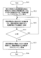
- FIG. 5 is a flowchart showing a flow of suggestion adjustment processing according to the present embodiment.
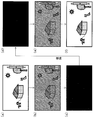
- FIG. 6 is a diagram illustrating a display example along the flow of processing.
- the process is started (Start: Step S1).
- the left-eye and right-eye image conversion processing units 1013 and 1014 cross-fade, that is, gradually darken the current image display shown in FIG. 5 (step S2 in FIG. 5 and (a) to (b) in FIG. 6), finally, a process of “another image” recorded in the converted image recording unit 1015 is performed (step in FIG. 5).
- S3, (c) of FIG. This process is sometimes referred to as dissolve.
- “another image” is preferably an image with little light stimulation, and may be a black screen as an example. In FIG. 6C, a black image is displayed.
- the relationship between convergence and adjustment differs depending on which position on the screen the observer is looking at. More specifically, the adjustment corresponds to the distance from the screen.
- this state there is a convergence according to the parallax of the object being observed and the depth is perceived.
- the screen is changed in this state, the parallax at the position that was viewed on the screen is changed abruptly.
- the line of sight is guided by the displayed parallax image, and is set to a convergence corresponding to the image.
- the change in the parallax before and after the screen change can be performed via the intended state. By guiding, stereoscopic viewing can be facilitated.
- An image that is easy to recognize is preferable, but may be a character, for example.
- the parallax adjustment unit 101 performs a process of holding another image display for 0.3 seconds or longer (step S4 in FIG. 5, (c) to (d) in FIG. 6).
- PES photosensitive seizures
- the parallax adjustment unit 101 crosses the display from “another image” recorded in the converted image recording unit 1015 to the image after parallax adjustment in the left-eye and right-eye image conversion processing units 1013 and 1014. Processing for fading is performed (step S5 in FIG. 5, (d)-(e) in FIG. 6). Next, the image after parallax adjustment is displayed (step S6 in FIG. 5, (f) in FIG. 6), thereby completing the parallax adjustment processing (step S7 in FIG. 5).
- the parallax adjustment unit 101 resets the state of congestion and adjustment of the observer to an intended state, and presents a screen on which further parallax adjustment has been performed to the observer. .
- the observer can perform the parallax adjustment without feeling a sense of incongruity in which the parallax is rapidly adjusted or a sense of movement accompanying the parallax being gradually adjusted.
- the “different image” is better if it is an image having a uniform parallax, and more preferably if it has an intermediate parallax between the pre-adjustment and post-adjustment images.
- the respective images are converted by the cross-fade process.
- This is a process for suppressing the movement of the image and reducing the light stimulus. . Therefore, this process is not limited to the crossfade process, and the object can be achieved by, for example, a wipe process.
- two images are given as the stereoscopic images.
- the number of images is not limited to two, and may be image data for a multi-viewpoint image.
- a time-division type stereoscopic display unit using shutter glasses is shown as a stereoscopic display system.
- the stereoscopic display system is not limited to the time-division type, and uses a parallax barrier or a lenticular lens. Any type of display system capable of stereoscopic viewing, such as a projector, may be used. As described above, a display for multi-viewpoint images may be used.
- the processing unit for inserting “another image” to be a conversion image is configured as the left-eye image conversion processing unit 1013 and the right-eye image conversion processing unit 1014 in the parallax adjustment unit 101. As long as it is performed between the parallax adjustment unit 101 and the display unit 103, it may be executed anywhere.
- the parallax adjustment unit 101 in FIG. 1 performs parallax adjustment according to the following three steps upon receiving an instruction to start parallax adjustment.
- FIG. 7 is a flowchart showing the flow of processing in the present embodiment.
- the parallax adjustment unit 101 records the current display in the converted image recording unit 1015 in the left and right eye image conversion processing units 1013 and 1014.
- a process of crossfading to “another image” is performed (step S12).
- “another image” reads an image corresponding to the current parallax amount setting from among the converted images recorded in the converted image recording unit 1015 (step S12).
- the converted image recording unit 1015 has, for example, a parallax amount corresponding to a settable parallax amount adjustment range, that is, an object at a distance corresponding to infinity on the back side of the screen from the image on which the object is displayed on the near side of the screen.
- a plurality of images in which the parallax continuously changes are recorded up to the image on which is displayed, and an image having a specific parallax can be obtained by reading the specific image.
- the part where the parallax is changed is a part of the image.
- the parallax adjustment unit 101 performs a process of displaying the converted image for 0.3 seconds or more.
- the converted image continuously displays from the converted image having the parallax before the parallax adjustment to the converted image having the parallax after the parallax adjustment, and the parallax continuously before and after the parallax adjustment.
- Processing to connect with the changing image is performed (steps S13 and S14).
- the part where the parallax changes is selected in association with the characteristic part of the stereoscopic image.
- the characteristic part may be a point that is likely to attract attention in the stereoscopic image.
- the parallax adjustment unit 101 performs a fade process of converting an image from a converted image corresponding to the parallax after parallax adjustment to a stereoscopic image after parallax adjustment (step S15). Thereby, the process ends (step S16: end).
- the parallax adjustment unit 101 once sets the observer's state of convergence and adjustment to an intended state, and presents the observer with a screen on which the parallax adjustment has been performed gradually.
- the observer feels that the object is not moving but the object is facing him Get. Thereby, the observer can perform the parallax adjustment without feeling a sense of incongruity in which the parallax is suddenly adjusted or a sense of movement accompanying the parallax being gradually adjusted.
- the converted image is a plurality of images having continuous parallax.
- the image obtained by such processing is used. May be.
- the region where the parallax changes is a part of the image, but the part of the region may be a region having a size that does not allow the observer to feel a sense of movement.
- the parallax of the stereoscopic image is obtained, and a converted image having a parallax corresponding to the parallax before and after the parallax adjustment is displayed, or the gaze point of the stereoscopic image is estimated, and the converted image corresponding to the parallax change of the place is the same It is even better to display it on the place.
- the parallax of the stereoscopic image is obtained from the left and right images, and there are several known methods for obtaining the parallax, such as block matching.
- FIG. 8 is a flowchart showing a flow of parallax amount adjustment processing in the present embodiment
- FIG. 9 is a view showing a display example along the flow of processing.
- the parallax adjustment unit 101 When the process is started (FIG. 8, step S21), as a first step, the parallax adjustment unit 101 superimposes and displays a mask pattern prepared in advance on the current display (FIG. 8: step S22, FIG. 9: (A)-(b)).
- the mask pattern is an image that blocks a partial region R1 of the image, and in the present embodiment, a pattern like a window that transmits only a partial region R2 of the image is adopted.
- the mask pattern may be translucent, but it is desirable that the mask pattern has a pattern and can guide the line of sight to the pattern itself. Here, it is possible to guide the line of sight to the letters “Adjusting”. By guiding the line of sight to the pattern itself, the vergence of the observer can be changed in accordance with the parallax of the pattern. It is preferable to display the mask pattern by performing a process of gradually shielding the mask pattern itself without moving it.
- the parallax adjustment unit 101 performs a process of displaying the mask pattern for 0.3 seconds or longer (step S23 in FIG. 8, (c) to (d) in FIG. 9). During this time, the parallax adjustment unit 101 performs parallax adjustment on the input stereoscopic image in a stepwise manner (step S24 in FIG. 8, (c) to (d) in FIG. 9). That is, it is observed that the parallax of the input stereoscopic image gradually changes from the transmission region R2 of the mask pattern. In FIG. 9D, the slide bar is slid from the back side to the near side.
- the parallax adjustment unit 101 performs display processing for removing the mask pattern (step S25 in FIG. 8, (e) to (f) in FIG. 9). It is preferable to perform a process of removing the mask pattern gradually by crossfade without moving the mask pattern itself.
- the parallax adjustment unit 101 continuously changes the state of congestion and adjustment of the observer while performing parallax adjustment gradually.
- the region that can be observed in the image on which the parallax adjustment is gradually performed is a part of the image, the observer feels not to be moving but to observe the moving object from the window. Thereby, the observer can perform the parallax adjustment without feeling a sense of incongruity in which the parallax is suddenly adjusted or a sense of movement accompanying the parallax being gradually adjusted.
- the size of the area may be a size that does not allow the observer to feel a sense of movement.
- stereoscopic image processing is performed using a personal computer (PC), and stereoscopic display is performed using a display device capable of stereoscopic display.
- PC personal computer
- a user performs a stereoscopic image process by operating a GUI application using an operation device of the PC, such as a mouse, a keyboard, or a touch panel.
- an operation device of the PC such as a mouse, a keyboard, or a touch panel.
- a CPU provided in the PC processes a moving image or a still image according to stereoscopic display application software recorded on a storage device, for example, a hard disk or a CD-ROM, and performs stereoscopic display on the stereoscopic display device.
- FIG. 10 is a diagram for explaining a display screen of the stereoscopic display device according to the fourth embodiment.
- the stereoscopic display device 210 is provided with a display unit 203, and the display unit 203 displays an image display 203a and a GUI display unit 203b.
- an operation unit 205 for playing, stopping, rewinding, fast-forwarding, a depth adjustment tab 211, and a slide bar 215 are displayed.
- a screen by a stereoscopic image display application is displayed on the image display unit 203a.
- the user can process a stereoscopic image by operating the setting buttons 211a to 211e and the slide bar 215 on the GUI display unit using an operation device such as a mouse or a keyboard.
- an operation device such as a mouse or a keyboard.
- display is performed according to any of the procedures in the above embodiments.
- a program for realizing the functions described in the present embodiment is recorded on a computer-readable recording medium, and the program recorded on the recording medium is read into a computer system and executed to execute processing of each unit. May be performed.
- the “computer system” here includes an OS and hardware such as peripheral devices.
- the “computer system” includes a homepage providing environment (or display environment) if a WWW system is used.
- the “computer-readable recording medium” means a storage device such as a flexible disk, a magneto-optical disk, a portable medium such as a ROM and a CD-ROM, and a hard disk incorporated in a computer system. Furthermore, the “computer-readable recording medium” dynamically holds a program for a short time like a communication line when transmitting a program via a network such as the Internet or a communication line such as a telephone line. In this case, a volatile memory in a computer system serving as a server or a client in that case, and a program that holds a program for a certain period of time are also included.
- the program may be a program for realizing a part of the above-described functions, or may be a program that can realize the above-described functions in combination with a program already recorded in a computer system.
- the present invention can be used for 3D television receivers and the like.
Landscapes
- Engineering & Computer Science (AREA)
- Multimedia (AREA)
- Signal Processing (AREA)
- Testing, Inspecting, Measuring Of Stereoscopic Televisions And Televisions (AREA)
- Controls And Circuits For Display Device (AREA)
Abstract
右目用画像と左目用画像とからなる立体視用画像を表示し、右目用画像を右目に、左目用画像を左目に呈示することにより立体視を可能とする立体視画像表示装置であって、右目用画像と左目用画像とからなる立体視用画像データの視差量を変化させるための視差量調整情報を入力する入力部と、立体視用画像データを構成する、右目用画像と左目用画像とのうち少なくともいずれか一方に処理を加え、視差を調整する視差調整部と、立体視用画像データの右目用画像及び左目用画像をそれぞれ右目及び左目に呈示し、立体画像を表示する表示手段と、視差調整部が、入力部から入力された視差量調整情報に基づき、立体視用画像データの視差量を調整する際に、調整前の表示画面と調整後の表示画面の間に、画像の一部を覆い隠すように、現在視差量を調整中の画像とは異なる別の画像を表示する画像転換処理部を有する。これにより視差の調整を行う際、奥行き方向の画像位置変動に対して観察者の違和感や3D酔いを避け、快適な立体視を実現することができる。
Description
本発明は、立体画像を表示する装置に関し、特に立体画像の立体感を調整する際の表示方法、立体画像表示プログラム、及びこれを記録したコンピュータ読み取り可能な記録媒体に関するものである。
人間は一定の間隔を持つ2つの目により得られる画像の違いから空間を把握する能力を持つ。左右の眼による異なる視点から得られる画像中の対応点のずれを視差と呼び、視差を手掛かりの一つとして対象物の位置関係を立体的に把握している。このことを利用して、右目用画像を右目に表示し、左目用画像を左目に表示する手段を設けて、右目用画像、左目用画像として視差を設けた画像を提示することにより立体視が可能であることが知られている。ここでは、立体視を意図して視差を設けた複数の画像のことを立体画像と称する。
立体視において、人間は視差に応じた両眼の光軸のなす角度、すなわち輻輳の大きさを対象物までの距離に対応付けていると言われている。よって、右目用画像を右に、左目用画像を左に相対的にずらし、視差を付けた画像を見せると、実際の表示面より遠くに表示物を知覚させることができる。しかし、このときに視差をつけすぎ、観察者の目の間隔、正確には無限遠を見ている時の瞳孔間の距離を超えた視差とすると、自然界では起き得ない状態となり、立体視が不可能となる。同様に、近距離側でも極端な視差は不自然な位置関係を生じ、また、極度な寄り目を観察者に強いることとなり、快適な立体視ができなくなる。このように、立体画像の視差量がある一定の範囲では快適に立体視が可能であるが、視差量が大きくなると両目の画像が融合しなくなり、立体視が不可能となる。
そこで、視差量が大きすぎて立体視しにくい、あるいは立体視が不可能な立体画像を表示する際に、左右画像の表示位置を左右にずらすことで視差を調整し、立体画像を見やすく表示する方法が、以下の特許文献1に示されている。
また、2つの立体画像を連続して表示する際、視差の小さな補間画像を作って、徐々に視差を変更するように表示する方法が、以下の特許文献2に示されている。
特許文献1の方法によれば、左右画像の表示位置をずらすことによって視差調整を行い、表示している物体の奥行き位置を全体的に前後させ、表示している物体を融合しやすくすることができる。しかしながら、左右画像を表示したまま表示位置を左右にずらすと、表示している画像の奥行き方向の表示位置が変化し、視差量切り替えの瞬間に立体視ができなくなるか、できたとしても表示物が観察者に対して急激に前後方向に移動した感覚を起こさせ、違和感を生じさせる。
そこで、特許文献2の方法に従い、視差調整を行う際、視差量を徐々に変更するような処理を行うと、観察者は連続して立体視を続けることができる。しかしながら、特に観察者の視界に占める表示画面の大きさが大きい場合や、集中して画面を観察している場合には、観察者は視差量の変化に伴い、あたかも奥行き方向、すなわち観察者にとっては前後方向に移動したかのような感覚を得る。移動を伴わないにもかかわらず移動した感覚があると、感覚の不一致(Sensory Conflict)として違和感を覚え、条件によっては乗り物酔いに近い状態である映像酔い、特に立体視に固有の奥行き方向の移動に関しての問題である、いわゆる3D酔いを生ずることがある。
3D酔いを避けるために、視差調整を人間に知覚できないほどゆっくり行う方法がある。しかしながら、一般的に船酔いの起きやすい振動周期は6秒といわれる。映像酔いと乗り物酔いは必ずしも同じメカニズムによるものとはいえないが、仮にこの6秒周期より十分に長い周期で、移動を知覚できないほどゆっくりと視差調整を行うとすると、かなりの長時間が必要となってしまう。
本発明の目的は、視差の調整を行う際、奥行き方向の画像位置変動に対して観察者の違和感や3D酔いを避け、快適な立体視を実現する立体画像表示装置、立体画像表示方法、その方法をコンピュータに実行させるためのプログラム及びそのプログラムを記録した記録媒体を提供することである。
本発明の一観点によれば、右目用画像と左目用画像とからなる立体視用画像を表示し、前記右目用画像を右目に、前記左目用画像を左目に呈示することにより立体視を可能とする立体視画像表示装置であって、右目用画像と左目用画像とからなる立体視用画像データの視差量を変化させるための視差量調整情報を入力する入力部と、前記立体視用画像データを構成する、前記右目用画像と前記左目用画像とのうち少なくともいずれか一方に前記視差量調整情報に基づく処理を加え、視差を調整する視差調整部と、前記立体視用画像データの前記右目用画像及び前記左目用画像をそれぞれ右目及び左目に呈示し、立体画像を表示する表示部と、前記視差調整部が、前記入力部から入力された視差量調整情報に基づき、前記立体視用画像データの視差量を調整する際に、調整前の表示画面と調整後の表示画面の表示の間に、現在視差量を調整中の画像とは異なる別の画像を表示する画像転換処理部と、を有することを特徴とする立体画像表示装置が提供される。これにより、違和感なく奥行き位置を調整することができる。
前記別の画像を、画像の一部を覆い隠すように表示させるようにしても良い。
前記画像転換処理部は、前記別の画像として、模様のない一様な画像を表示させることが好ましい。このようにすると、簡単なハードウエアで実現することができる。
前記画像転換処理部は、前記別の画像として、一様な視差を持つ画像を表示させることが好ましい。画像転換中の観察者の輻輳角を意図した角度に設定できる。
前記画像転換処理部は、前記別の画像として、調整前の画像の視差と調整後の画像の視差の間の値の視差を有する画像を表示させることが好ましい。これにより、視差をスムーズに変更することができる。
前記画像転換処理部は、前記別の画像として、連続的に視差が変更される複数の画像を表示させることが好ましい。これにより、画像転換中の観察者の輻輳角を意図的に制御することができる。
連続的に視差が変更される複数の画像からなる前記別の画像は、視差が変更される部分が画面の一部であることが好ましい。これにより、3D酔いを避けることができる。
連続的に視差が変更される複数の画像からなる前記別の画像のうち、視差が変更される部分は、前記立体視用画像データの特徴的な部分に基づいて決定されることが好ましい。これにより、視差を違和感なく変更することができる。
連続的に視差が変更される複数の画像からなる前記別の画像は、調整前の画像の視差から調整後の画像の視差へと連続的に視差が変更されるように選択されることが好ましい。これにより、視差をスムーズに変更することができる。
前記別の画像を表示する時間は、0.3秒以上であることが好ましい。これにより、映像酔いを防ぐことができる。
前記調整前の表示画面から前記別の画像への転換時、及び、前記別の画像から前記調整後の画像への転換時の表示画面のうち、少なくともいずれか一方にクロスフェード処理を施すことが好ましい。これにより、映像の刺激を弱め、疲労を軽減することができる。
前記調整前の表示画面から前記別の画像への転換時、及び前記別の画像から前記調整後の画像への転換時の表示画面のうち、少なくともいずれか一方にワイプ処理を施すことが好ましい。これにより、映像の刺激を弱め、疲労を軽減することができる。
前記調整前の表示画面から前記別の画像への転換時、及び前記別の画像から前記調整後の画像への転換時の表示画面のうち、少なくともいずれか一方にワイプ処理を施すことが好ましい。これにより、映像の刺激を弱め、疲労を軽減することができる。
本発明の他の観点によれば、右目用画像と左目用画像とからなる立体視用画像を表示し、前記右目用画像を右目に、前記左目用画像を左目に呈示することにより立体視を可能とする立体視画像表示方法であって、右目用画像と左目用画像とからなる立体視用画像データの視差量を変化させるための視差量調整情報を入力するステップと、前記立体視用画像データを構成する、前記右目用画像と前記左目用画像とのうち少なくともいずれか一方に前記視差量調整情報に基づく処理を加え、視差を調整する視差調整ステップと、前記立体視用画像データの前記右目用画像及び前記左目用画像をそれぞれ右目及び左目に呈示し、立体画像を表示する表示ステップと、を有し、前記視差調整ステップにおいて、前記入力するステップにより入力された視差量調整情報に基づき、前記立体視用画像データの視差量を調整する際に、調整前の表示画面と調整後の表示画面の表示の間に、現在視差量を調整中の画像とは異なる別の画像を表示するステップを有することを特徴とする立体画像表示方法が提供される。
前記視差調整ステップにおいて、現在視差量を調整中の画像とは異なる別の画像を表示するステップは、画像の一部を覆い隠すようにしても良い。
本発明は、コンピュータに、上記に記載の立体画像表示方法を実行させるためのプログラムであっても良く、当該プログラムを記録するコンピュータ読み取り可能な記録媒体であっても良い。
本明細書は本願の優先権の基礎である日本国特許出願2010-207056号の明細書および/または図面に記載される内容を包含する。
本発明によれば、視差の調整を行う際、視差を変更することに伴う違和感や3D酔いを避け、快適な立体視を実現することができる。
<第1の実施形態>
以下に、本発明の第1の実施形態による立体画像表示装置について、図面を参照して説明する。図1は、本実施形態による立体画像表示装置の構成例を示すブロック図である。図1が示すように、本実施形態による立体画像表示装置Aは、入力部10と、入力された画像データを処理し、立体表示が可能な表示データ(以下、立体視用画像データ)を生成するための画像処理を行う立体画像処理部100と、画像の視差を調整する視差調整部101と、画像を表示部に合わせ表示制御を行う表示制御部102と、画像を表示する表示部103と、システム全体を制御するシステム制御部104と、ユーザが入力を行うユーザ入力部105と、シャッタメガネの同期を行うメガネ同期部106と、から構成され、別途、ユーザが装着するシャッタメガネ107を用いる。
以下に、本発明の第1の実施形態による立体画像表示装置について、図面を参照して説明する。図1は、本実施形態による立体画像表示装置の構成例を示すブロック図である。図1が示すように、本実施形態による立体画像表示装置Aは、入力部10と、入力された画像データを処理し、立体表示が可能な表示データ(以下、立体視用画像データ)を生成するための画像処理を行う立体画像処理部100と、画像の視差を調整する視差調整部101と、画像を表示部に合わせ表示制御を行う表示制御部102と、画像を表示する表示部103と、システム全体を制御するシステム制御部104と、ユーザが入力を行うユーザ入力部105と、シャッタメガネの同期を行うメガネ同期部106と、から構成され、別途、ユーザが装着するシャッタメガネ107を用いる。
図2は、視差調整部101の構成例を示す図である。図2に示すように、視差調整部101は、左目用の画像ずらし処理部1011及び右目用の画素ずらし処理部1012と、左目用の画像転換処理部1013及び右目用の画像転換処理部1014と、転換画像記録部1015と、通信・制御部1016と、を有して構成される。 次に、各構成部の動作について説明する。
立体画像表示装置Aにおいて、入力部10を経由して入力された画像データは、立体画像処理部100において、入力形式に合わせて、左目用画像データと右目用画像データとに展開される。同時に、入力された画像データに付加情報がある場合は付加情報を抽出し、システム制御部104に伝送する。ここで、入力される画像データは、放送波によるもの、記録メディアから電子的に読みだされたもの、ネットワークから伝送されたものなど、どのようなものでも構わない。また、右目用画像データ、左目用画像データは、1枚の画像データから作成されたものでも良い。すなわち、画像データと奥行きデータから合成された複数視点画像、奥行き情報を推定して作成された複数視点画像であってもよい。
展開された左目用画像データと右目用画像データとは、視差調整部101に送られ、視差を調整される。視差調整部101の内部では、システム制御部104と通信する通信・制御部1016が各構成部を制御している。左目用画像ずらし処理部1011及び右目用画像ずらし処理部1012は、システム制御部104の指示(視差量調整情報)を、通信・制御部1016を経由して受け、左目用画像及び右目用画像をそれぞれ左右にずらす処理を行い、視差を調整する。視差が調整された左右目用画像データは、それぞれ左目用画像転換処理部1013及び右目用1014に入力される。左目用画像転換処理部1013及び右目用画像転換処理部1014には、転換画像記録部1015からの画像データも入力可能であり、通信・制御部1016を経由してシステム制御部104からの指示を受け、入力された左右目用画像及び転換画像となる別の画像との間で画像を転換する処理を行う。
視差が調整された左目用画像と右目用画像とは、表示制御部102に送られる。表示制御部102は、表示部103に合わせた表示制御をするとともに、メガネ同期部106に対し信号を送る。メガネ同期部106は、ユーザの装着するシャッタメガネ107に対し同期信号を送り、表示部103と同期処理が行われる。より具体的には、例えば、表示部103に液晶表示パネルを用い、左目用画像と右目用画像とを交互に表示し、観察者の装着したシャッタメガネ107と同期して立体視を行う方式の場合、表示制御部102は表示部103に対し、左目用画像と右目用画像とを交互に出力する。出力の頻度は、例えば左目用画像と右目用画像をそれぞれ毎秒120枚とする。表示部103は、表示制御部102から送られる画像を随時表示するが、表示部103に左目用画像が表示されているときはシャッタメガネ107の左目用シャッタを開にし、右目用シャッタを閉とすることにより左目用画像を左目に表示し、右目用画像が表示されているときには左目用シャッタを閉にし、右目用シャッタを開とすることにより右目用画像を右目に表示して、立体視を実現する。
観察者は、ユーザ入力部105を用いて、表示する画面の視差量調整用データを入力する。ユーザ入力部105は、例えばリモコンなどで実現できるが、キーボードやマウス、タッチパネル、ダイヤルなど、いろいろな手段により実現することができ、その形式を問わず、ジェスチャ認識などであっても良い。ユーザ入力部105より入力された視差量調整用データは、システム制御部104を経由して視差調整部101に伝達される。視差調整部101では、受け取った視差量調整用データに基づき、視差調整処理を行う。視差量調整用データが視差調整なしを表すデータであった場合には、視差調整部101では視差調整処理を行わず、そのまま左右目用画像データを出力する。
次に、視差と奥行き表示との関係を図3に示す。図3は観察者とディスプレイを上から見た図である。図3(a)は、通常の2次元表示状態であり、立体画像表示時には、右目用画像と左目用画像の対応点がディスプレイ(表示面)上で同じ位置にある状態である。この場合、この対応点はディスプレイ上にあるように知覚される。図3(b)は、ディスプレイ上で、右目用画像と左目用画像との対応点P2、P3が、右目用画像は右に、左目用画像は左にずれた状態である。この状態では、観察者にはこの点はディスプレイ面よりも奥に知覚される(P4)。
図3(c)は、ディスプレイ上で、右目用画像と左目用画像の対応点P5、P6が、右目用画像は左に、左目用画像は右にずれた状態である。この状態では、観察者にはこの点はディスプレイ面よりも手前に知覚される(P7)。
図3(d)は、これらをまとめた図である。前述したとおり、右目用画像と左目用画像の対応点が、右目用画像が右、左目用画像が左にずれて表示され、かつ対応点間の距離が両眼距離に等しい場合、この点は無限遠に知覚されるが、対応点間の距離が両眼距離を超えた場合、視線は開散方向にはならず、融合できなくなる。同様に、ディスプレイ上で、右目用画像と左目用画像の対応点が、右目用画像は左に、左目用画像は右に大きくずれた状態では(P8、P9)、視線は極端な寄り目状態となり、融合できなくなる。従って、快適に立体視できる奥行きの範囲、すなわち、図3(d)に示した快適融合範囲は、これらの融合範囲よりもディスプレイ面に対し内側となる。
これらの原理を応用し、左右目用画像を相対的に左右にずらすことによって、立体画像の奥行き感を全体的に奥や手前に移動することができる。
ここで、観察者の実際の操作例を示す。観察者は、ユーザ入力部105を操作して、視差量を調整するモードに入る。図4に視差量調整モードにおける表示部103における表示例を示す。図4に示す状態では、表示部には画像と、スライドバー103aとが表示されており、この状態でユーザ入力部105を操作することにより画面右に表示されているスライドバー103aを矢印のように移動させ、対応する視差調整量を設定することができる。
観察者による上記の操作により、システム制御部104は視差調整部101に左右画像のずらし量を設定するとともに、視差調整の開始を指示する。視差調整部101は、視差調整開始の指示を受けると、以下の3ステップに従って視差調整を行う。
図5は、本実施の形態による示唆調整処理に流れを示すフローチャート図である。図6は、処理の流れに沿った表示例を示す図である。
処理を開始し(Start:ステップS1)、第1ステップとして、左目用及び右目用の画像転換処理部1013及び1014において、図4に示す現在の画像表示を、クロスフェード、すなわち、徐々に暗くしていき(図5のステップS2、図6の(a)から(b))、最終的には、転換画像記録部1015に記録された「別の画像」とする処理を行う(図5のステップS3、図6の(c))。この処理はディゾルブ等と称されることもある。ここで、「別の画像」は光刺激の少ないものが好ましく、一例として黒画面でもよい。図6(c)では、黒画像を表示させている。
また、「別の画像」によって、意図的に輻輳と調節の状態を意図した状態に設定し直すことも可能であり、それに合わせた画像を用意しておくとよい。
例えば、奥行きを持つ立体画像を観察している時、観察者は画面上のどの位置を見ているかによって輻輳と調節の関係が異なり、より具体的には、調節は画面との距離に対応している状態で、観察している物体の視差に合わせた輻輳をもち、奥行きを知覚している状態にある。この状態で画面が転換されると、画面上の見ていた位置の視差は急激に転換されることになる。この現象を避けるために、例えば模様のない一様な背景画面の小領域に意図した視差の画像を表示すると、視線は表示した視差画像に誘導され、画像に合わせた輻輳に設定される。この状態で次の画面に転換すれば、画面の転換前後の視差変化を意図した状態を経由して行うことができ、例えば転換後の画像のうち、融像しやすい視差のない領域に視線を誘導することにより立体視を容易にすることができる。
画像としては認識しやすいものが好ましいが、例えば文字などでもよい。
次に、第2ステップとして、視差調整部101は、別の画像の表示を0.3秒以上保持する処理を行う(図5のステップS4、図6の(c)-(d))。
人間は、光の明滅など、強い光刺激を受けると光感受性発作(PSS)を起こすことがある。光感受性発作を避ける目的で、強い光刺激となりうる1秒間に3回以上の明滅を避けるよう勧告されている。また、一般的に人間が物体に対しピントを調節するのにおよそ0.2秒かかると言われている。従って、立体視により輻輳とピント位置の調節が不一致の状態から、輻輳と調節が一致した状態に一旦戻すのにも同程度かかると推測される。これらのことから、第2ステップの継続時間は0.3秒以上とするのが望ましい。
第3ステップとして、視差調整部101は、左目用及び右目用の画像転換処理部1013及び1014において、表示を転換画像記録部1015に記録された「別の画像」から視差調整後の画像へクロスフェードさせる処理を行う(図5のステップS5、図6の(d)-(e))。次いで、視差調整後の画像を表示させる(図5のステップS6、図6の(f)。これにより、視差調整処理を終了する(図5のステップS7)。
図5、図6に示す処理を行うことにより、視差調整部101は、観察者の輻輳と調節の状態を一旦意図した状態に設定し直し、更に視差調整を行った画面を観察者に呈示する。それにより観察者が、急激に視差が調整される違和感や、徐々に視差が調整されることに伴う移動の感覚を感じることなく、視差調整を行うことができる。上記の理由で、「別の画像」は、一様な視差を持つ画像であるとよりよく、さらに調整前と調整後の画像の持つ視差の中間の視差を持つとなお良い。
尚、上記の第1のステップと第3のステップとでは、それぞれの画像をクロスフェード処理で転換しているが、これは画像の移動を抑え、かつ、光刺激を低減させるための処理である。従って、この処理はクロスフェード処理に限定されるものではなく、例えばワイプ処理などでも目的を果たすことができる。
また、上記の例では、立体画像として右目用画像と左目用画像との2つを挙げたが、画像は2つに限定されるものではなく、多視点画像用の画像データであっても良い。また、立体視可能な表示システムとしてシャッタメガネを用いた時分割方式の立体表示手段を示したが、立体表示システムは時分割方式に限定するものではなく、パララクスバリアによるもの、レンチキュラレンズを用いるもの、プロジェクタによるものなど、立体視が可能な表示システムなら形式を問わない。前述のとおり、多視点画像を対象としたディスプレイであっても良い。
さらに、転換画像となる「別の画像」を挿入する処理部を、視差調整部101の中に左目用画像転換処理部1013及び右目用画像転換処理部1014として構成したが、転換画像挿入処理は、視差調整部101と表示部103の間で行われればどこで実行されても良い。
以上に説明したように、本実施の形態によれば、視差量を調整する際に、光刺激の少ない「別の画像」を所定時間だけ表示させることにより、視差を変更することに伴う違和感や3D酔いを避け、快適な立体視を簡単に実現することができる。
<第2の実施形態>
以下に、本発明の第2の実施形態による立体画像表示装置について説明する。第2の実施形態においては、第1の実施形態の中の視差調整のステップの内容のみが第1の実施形態の内容と異なる。それ以外のハードウエア構成やユーザインタフェースの実現の仕方は第1の実施形態において説明したもので実現可能であり、その詳細な説明を省略する。
以下に、本発明の第2の実施形態による立体画像表示装置について説明する。第2の実施形態においては、第1の実施形態の中の視差調整のステップの内容のみが第1の実施形態の内容と異なる。それ以外のハードウエア構成やユーザインタフェースの実現の仕方は第1の実施形態において説明したもので実現可能であり、その詳細な説明を省略する。
本実施の形態においては、図1の視差調整部101は、視差調整開始の指示を受けると、以下の3ステップに従って視差調整を行う。図7は、本実施の形態における処理の流れを示すフローチャート図である。
処理を開始すると、(Start:ステップS11)、第1のステップとして、視差調整部101は、左右目用画像転換処理部1013及び1014において、現在の表示を転換画像記録部1015に記録された「別の画像」にクロスフェードする処理を行う(ステップS12)。この際、「別の画像」は、転換画像記録部1015に記録された転換画像のうち、現在の視差量設定に対応する画像を読み出す(ステップS12)。
尚、転換画像記録部1015には、例えば、設定可能な視差量調整範囲に対応した視差量、すなわち画面手前側に物体が表示されている画像から画面奥側の無限遠に対応する距離に物体が表示されている画像まで、視差が連続的に変化する複数の画像が記録されており、特定の画像を読み出すことにより特定の視差を持つ画像を得ることができる。また、記録された転換画像の中で、視差を変化させる部分は画像の一部であることとする。
第2のステップとして、視差調整部101は、転換画像を0.3秒以上表示する処理を行う。この際、転換画像は、視差が変化する部分が視差調整前の視差を持つ転換画像から視差調整後の視差を持つ転換画像までを連続的に表示し、視差調整の前後を連続的に視差が変化する画像でつなぐ処理を行う(ステップS13、S14)。なお、この際、視差が変化する部分は立体視画像の特徴的な部分と対応付けて選択されるようにするとなお良い。特徴的な部分とは、具体的には、立体視画像の中で注目を集めそうな点であるとよい。
第3のステップとして、視差調整部101は、視差調整後の視差に対応する転換画像から、視差調整後の立体画像へ画像を転換するフェード処理を行う(ステップS15)。これにより処理が終了する(ステップS16:end)。
以上の3ステップで、視差調整部101は、観察者の輻輳と調節の状態を一旦意図した状態に設定し、徐々に視差調整を行った画面を観察者に呈示する。ここで、徐々に視差調整を行う転換画像のうち視差量が変化する領域は画像の一部であることから、観察者は自分が移動しているのではなく、物体が自分に向かってくる感覚を得る。それにより観察者は、急激に視差が調整される違和感や、徐々に視差が調整されることに伴う移動の感覚を感じることなく、視差調整を行うことができる。
尚、上記の例では、転換画像は連続する視差を持つ複数の画像としたが、視差調整処理や立体画像合成処理により同様の画像が得られる場合はそのような処理によって得られた画像を用いても良い。また、視差が変化する領域は画像の一部としたが、その一部の領域とは、観察者が移動感覚を感じない程度の大きさの領域であればよい。また、立体画像の視差を求めて、視差調整前後の視差に対応した視差を持つ転換画像を表示したり、立体画像の注視点を推定して、その場所の視差変化に対応した転換画像を同じ場所に表示したりするとなお良い。この場合、立体画像の視差は左右画像から得られ、視差を得る方法はブロックマッチングなど、いくつかの公知の方法がある。
<第3の実施形態>
以下に、本発明の第3の実施形態による立体画像表示装置について説明する。第3の実施形態においては、第1の実施形態の中の視差調整のステップの内容のみが第1の実施形態の内容と異なる。それ以外のハードウエア構成やユーザインタフェースの実現の仕方は第1の実施形態において説明したもので実現可能であり、その詳細な説明を省略する。図8は、本実施の形態における視差量調整処理の流れを示すフローチャート図であり、図9は、処理の流れに沿った表示例を示す図である。
以下に、本発明の第3の実施形態による立体画像表示装置について説明する。第3の実施形態においては、第1の実施形態の中の視差調整のステップの内容のみが第1の実施形態の内容と異なる。それ以外のハードウエア構成やユーザインタフェースの実現の仕方は第1の実施形態において説明したもので実現可能であり、その詳細な説明を省略する。図8は、本実施の形態における視差量調整処理の流れを示すフローチャート図であり、図9は、処理の流れに沿った表示例を示す図である。
図1の視差調整部101は、視差調整開始の指示を受けると、以下の3ステップに従って視差調整を行う。
処理を開始すると(図8、ステップS21)、第1のステップとして、視差調整部101は、現在の表示に、予め用意したマスクパターンを重畳して表示する(図8:ステップS22、図9:(a)-(b))。ここで、マスクパターンとは、画像の一部領域R1を遮蔽する画像であり、本実施形態では、画像の一部の領域R2のみ透過する、窓のようなパターンを採用する。なお、このマスクパターンは、半透明であっても良いが、模様があり、パターン自体に視線を誘導できるものの方が望ましい。ここでは、「調整中です」という文字に視線を誘導できるようにしている。パターン自体に視線を誘導することにより、パターンの持つ視差に合わせて観察者の輻輳を変化させることができる。マスクパターンの表示は、マスクパターン自体を動かさず、かつ徐々に遮蔽するような処理を行った方が好ましい。
第2のステップとして、視差調整部101は、マスクパターンを0.3秒以上表示する処理を行う(図8のステップS23、図9の(c)-(d))。この間に、視差調整部101は、入力された立体画像に段階的に視差調整を施す(図8のステップS24、図9の(c)-(d))。すなわち、マスクパターンの透過領域R2から、入力された立体画像の視差が徐々に変化していくさまが観察されるようにする。図9(d)では、スライドバーが奥側から手前側にスライドされている。
第3のステップとして、視差調整部101は、マスクパターンを取り除く表示処理を行う(図8のステップS25、図9の(e)-(f))。マスクパターン自体を動かさず、かつ徐々にクロスフェードで取り除くような処理を行った方が好ましい。
以上の3ステップにおいて、視差調整部101は、徐々に視差調整を行ないつつ、観察者の輻輳と調節の状態を連続的に変化させる。ここで、徐々に視差調整を行う画像のうち観察できる領域は画像の一部であることから、観察者は自分が移動しているのではなく、窓から動く物体を観察する感覚を得る。それにより観察者は、急激に視差が調整される違和感や、徐々に視差が調整されることに伴う移動の感覚を感じることなく、視差調整を行うことができる。
なお、マスクパターンの透過領域は画像の一部としたが、その領域の大きさは、観察者が移動感覚を感じない程度の大きさであればよい。
<第4の実施形態>
本発明の第4の実施形態においては、パーソナルコンピュータ(PC)を用いて立体画像処理を行い、立体表示可能な表示デバイスを用いて立体表示する。PC上では、ユーザがPCの操作デバイス、例えばマウスやキーボード、タッチパネル等を用いて、GUIアプリケーションを操作して立体画像処理を行う。すなわち、PCに供えられたCPUが記憶装置、例えばハードディスクやCD-ROMに記録されている立体表示アプリケーションソフトウェアに従って、動画や静止画に対し処理を行い、立体表示デバイスに立体表示をする。
本発明の第4の実施形態においては、パーソナルコンピュータ(PC)を用いて立体画像処理を行い、立体表示可能な表示デバイスを用いて立体表示する。PC上では、ユーザがPCの操作デバイス、例えばマウスやキーボード、タッチパネル等を用いて、GUIアプリケーションを操作して立体画像処理を行う。すなわち、PCに供えられたCPUが記憶装置、例えばハードディスクやCD-ROMに記録されている立体表示アプリケーションソフトウェアに従って、動画や静止画に対し処理を行い、立体表示デバイスに立体表示をする。
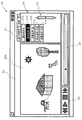
図10は、第4の実施形態による立体表示デバイスの表示画面を説明する図である。立体表示デバイス210には、表示部203が設けられ、表示部203には、画像表示203aと、GUI表示部203bとが表示されている。GUI表示部203bには、再生、停止、巻き戻し、早送りなどをするための操作部205と、奥行き調整タブ211とスライドバー215とが表示さえている。画像表示部203aには、立体画像表示アプリケーションによる画面が表示されている。ユーザはマウスやキーボード等の操作デバイスを用いて、GUI表示部上の設定ボタン211a~211eやスライドバー215を操作することにより、立体画像を処理することができる。ここで視差調整を行う際には、上記の各実施の形態におけるいずれかの手順で表示を行う。
また、上記の実施の形態において、添付図面に図示されている構成等については、これらに限定されるものではなく、本発明の効果を発揮する範囲内で適宜変更することが可能である。その他、本発明の目的の範囲を逸脱しない限りにおいて適宜変更して実施することが可能である。
また、本実施の形態で説明した機能を実現するためのプログラムをコンピュータ読み取り可能な記録媒体に記録して、この記録媒体に記録されたプログラムをコンピュータシステムに読み込ませ、実行することにより各部の処理を行ってもよい。尚、ここでいう「コンピュータシステム」とは、OSや周辺機器等のハードウェアを含むものとする。
また、「コンピュータシステム」は、WWWシステムを利用している場合であれば、ホームページ提供環境(あるいは表示環境)も含むものとする。
また、「コンピュータ読み取り可能な記録媒体」とは、フレキシブルディスク、光磁気ディスク、ROM、CD-ROM等の可搬媒体、コンピュータシステムに内蔵されるハードディスク等の記憶装置のことをいう。さらに「コンピュータ読み取り可能な記録媒体」とは、インターネット等のネットワークや電話回線等の通信回線を介してプログラムを送信する場合の通信線のように、短時間の間、動的にプログラムを保持するもの、その場合のサーバやクライアントとなるコンピュータシステム内部の揮発性メモリのように、一定時間プログラムを保持しているものも含むものとする。また前記プログラムは、前述した機能の一部を実現するためのものであっても良く、さらに前述した機能をコンピュータシステムにすでに記録されているプログラムとの組み合わせで実現できるものであっても良い。
本発明は、3Dテレビジョン受信装置などに利用可能である。
10 入力部
100 立体画像処理部
101 視差調整部
102 表示制御部
103 表示部
104 システム制御部
105 ユーザ入力部
106 メガネ同期部
107 シャッタメガネ
1011 左目用画像ずらし処理部
1012 右目用画像ずらし処理部
1013 左目用画像転換処理部
1014 右目用画像転換処理部
1015 転換画像記録部
1016 通信・制御部
本明細書で引用した全ての刊行物、特許および特許出願をそのまま参考として本明細書にとり入れるものとする。
100 立体画像処理部
101 視差調整部
102 表示制御部
103 表示部
104 システム制御部
105 ユーザ入力部
106 メガネ同期部
107 シャッタメガネ
1011 左目用画像ずらし処理部
1012 右目用画像ずらし処理部
1013 左目用画像転換処理部
1014 右目用画像転換処理部
1015 転換画像記録部
1016 通信・制御部
本明細書で引用した全ての刊行物、特許および特許出願をそのまま参考として本明細書にとり入れるものとする。
Claims (15)
- 右目用画像と左目用画像とからなる立体視用画像を表示し、前記右目用画像を右目に、前記左目用画像を左目に呈示することにより立体視を可能とする立体視画像表示装置であって、
右目用画像と左目用画像とからなる立体視用画像データの視差量を変化させるための視差量調整情報を入力する入力部と、
前記立体視用画像データを構成する、前記右目用画像と前記左目用画像とのうち少なくともいずれか一方に前記視差量調整情報に基づく処理を加え、視差を調整する視差調整部と、
前記立体視用画像データの前記右目用画像及び前記左目用画像をそれぞれ右目及び左目に呈示し、立体画像を表示する表示部と、
前記視差調整部が、前記入力部から入力された視差量調整情報に基づき、前記立体視用画像データの視差量を調整する際に、調整前の表示画像と調整後の表示画像の表示の間に、現在視差量を調整中の画像とは異なる別の画像を表示する画像転換処理部と、を有することを特徴とする立体画像表示装置。 - 前記別の画像を、画像の一部を覆い隠すように表示させることを特徴とする請求項1に記載の立体画像表示装置。
- 前記画像転換処理部は、前記別の画像として、一様な視差を持つ画像を表示させることを特徴とする、請求項1又は2に記載の立体画像表示装置。
- 前記画像転換処理部は、前記別の画像として、調整前の画像の視差と調整後の画像の視差の間の値の視差を有する画像を表示させることを特徴とする、請求項3に記載の立体画像表示装置。
- 前記画像転換処理部は、前記別の画像として、連続的に視差が変更される複数の画像を表示させることを特徴とする、請求項1又は2に記載の立体画像表示装置。
- 連続的に視差が変更される複数の画像からなる前記別の画像は、視差が変更される部分が画面の一部であることを特徴とする、請求項5に記載の立体画像表示装置。
- 連続的に視差が変更される複数の画像からなる前記別の画像のうち、視差が変更される部分は、前記立体視用画像データの特徴的な部分に基づいて決定されることを特徴とする、請求項6に記載の立体画像表示装置。
- 連続的に視差が変更される複数の画像からなる前記別の画像は、調整前の画像の視差から調整後の画像の視差へと連続的に視差が変更されるように選択されることを特徴とする、請求項5に記載の立体画像表示装置。
- 前記別の画像を表示する時間は、生体への影響度に基づいた時間であることを特徴とする、請求項1から8までのいずれか1項に記載の立体画像表示装置。
- 前記調整前の表示画面から前記別の画像への転換時、及び、前記別の画像から前記調整後の画像への転換時の表示画面のうち、少なくともいずれか一方にクロスフェード処理を施すことを特徴とする、請求項1から9までのいずれか1項に記載の立体画像表示装置。
- 前記調整前の表示画面から前記別の画像への転換時、及び前記別の画像から前記調整後の画像への転換時の表示画面のうち、少なくともいずれか一方にワイプ処理を施すことを特徴とする、請求項1から9のいずれか1項に記載の立体画像表示装置。
- 右目用画像と左目用画像とからなる立体視用画像を表示し、前記右目用画像を右目に、前記左目用画像を左目に呈示することにより立体視を可能とする立体視画像表示方法であって、
右目用画像と左目用画像とからなる立体視用画像データの視差量を変化させるための視差量調整情報を入力するステップと、
前記立体視用画像データを構成する、前記右目用画像と前記左目用画像とのうち少なくともいずれか一方に前記視差量調整情報に基づく処理を加え、視差を調整する視差調整ステップと、
前記立体視用画像データの前記右目用画像及び前記左目用画像をそれぞれ右目及び左目に呈示し、立体画像を表示する表示ステップと、を有し、
前記視差調整ステップにおいて、前記入力するステップにより入力された視差量調整情報に基づき、前記立体視用画像データの視差量を調整する際に、調整前の表示画像と調整後の表示画像の表示の間に、現在視差量を調整中の画像とは異なる別の画像を表示するステップを有することを特徴とする立体画像表示方法。 - 前記視差調整ステップにおいて、現在視差量を調整中の画像とは異なる別の画像を表示するステップは、画像の一部を覆い隠すようにするステップを有することを特徴とする請求項12に記載の立体画像表示方法。
- コンピュータに、請求項12又は13に記載の立体画像表示方法を実行させるためのプログラム。
- 請求項14に記載のプログラムを記録するコンピュータ読み取り可能な記録媒体。
Applications Claiming Priority (2)
| Application Number | Priority Date | Filing Date | Title |
|---|---|---|---|
| JP2010-207056 | 2010-09-15 | ||
| JP2010207056A JP2012065111A (ja) | 2010-09-15 | 2010-09-15 | 立体画像表示装置、立体画像表示方法、立体画像表示方法をコンピュータに実行させるためのプログラム、及びそのプログラムを記録した記録媒体 |
Publications (1)
| Publication Number | Publication Date |
|---|---|
| WO2012036056A1 true WO2012036056A1 (ja) | 2012-03-22 |
Family
ID=45831519
Family Applications (1)
| Application Number | Title | Priority Date | Filing Date |
|---|---|---|---|
| PCT/JP2011/070441 Ceased WO2012036056A1 (ja) | 2010-09-15 | 2011-09-08 | 立体画像表示装置、立体画像表示方法、立体画像表示方法をコンピュータに実行させるためのプログラム、及びそのプログラムを記録した記録媒体 |
Country Status (2)
| Country | Link |
|---|---|
| JP (1) | JP2012065111A (ja) |
| WO (1) | WO2012036056A1 (ja) |
Cited By (1)
| Publication number | Priority date | Publication date | Assignee | Title |
|---|---|---|---|---|
| US9118911B2 (en) | 2013-02-07 | 2015-08-25 | Delphi Technologies, Inc. | Variable disparity three-dimensional (3D) display system and method of operating the same |
Citations (3)
| Publication number | Priority date | Publication date | Assignee | Title |
|---|---|---|---|---|
| JP2003209858A (ja) * | 2002-01-17 | 2003-07-25 | Canon Inc | 立体画像生成方法及び記録媒体 |
| JP2006165795A (ja) * | 2004-12-03 | 2006-06-22 | Canon Inc | 画像形成装置およびその方法 |
| JP2010199740A (ja) * | 2009-02-23 | 2010-09-09 | Fujifilm Corp | 立体画像表示装置及び立体画像表示方法 |
Family Cites Families (3)
| Publication number | Priority date | Publication date | Assignee | Title |
|---|---|---|---|---|
| JP2002092656A (ja) * | 2000-09-11 | 2002-03-29 | Canon Inc | 立体画像表示装置及び画像データの表示方法 |
| JP2002232913A (ja) * | 2001-01-31 | 2002-08-16 | Canon Inc | 複眼カメラ及び立体視画像観察システム |
| JP4637942B2 (ja) * | 2008-09-30 | 2011-02-23 | 富士フイルム株式会社 | 3次元表示装置および方法並びにプログラム |
-
2010
- 2010-09-15 JP JP2010207056A patent/JP2012065111A/ja active Pending
-
2011
- 2011-09-08 WO PCT/JP2011/070441 patent/WO2012036056A1/ja not_active Ceased
Patent Citations (3)
| Publication number | Priority date | Publication date | Assignee | Title |
|---|---|---|---|---|
| JP2003209858A (ja) * | 2002-01-17 | 2003-07-25 | Canon Inc | 立体画像生成方法及び記録媒体 |
| JP2006165795A (ja) * | 2004-12-03 | 2006-06-22 | Canon Inc | 画像形成装置およびその方法 |
| JP2010199740A (ja) * | 2009-02-23 | 2010-09-09 | Fujifilm Corp | 立体画像表示装置及び立体画像表示方法 |
Cited By (1)
| Publication number | Priority date | Publication date | Assignee | Title |
|---|---|---|---|---|
| US9118911B2 (en) | 2013-02-07 | 2015-08-25 | Delphi Technologies, Inc. | Variable disparity three-dimensional (3D) display system and method of operating the same |
Also Published As
| Publication number | Publication date |
|---|---|
| JP2012065111A (ja) | 2012-03-29 |
Similar Documents
| Publication | Publication Date | Title |
|---|---|---|
| JP5059922B2 (ja) | 立体画像生成装置、立体画像表示装置、立体画像調整方法、立体画像調整方法をコンピュータに実行させるためのプログラム、及びそのプログラムを記録した記録媒体 | |
| KR101926577B1 (ko) | 확장형 3차원 입체영상 디스플레이 시스템 | |
| WO2010084724A1 (ja) | 画像処理装置、プログラム、画像処理方法、記録方法および記録媒体 | |
| WO2007117471A2 (en) | Vertical surround parallax correction | |
| JP2011188118A (ja) | 表示装置、システム、及びメガネに関する | |
| JP2020137128A (ja) | コンピュータ読取可能な非一過性の記憶媒体、Webサーバ、及び、瞳孔間のキャリブレーション方法 | |
| KR20110080035A (ko) | 3d 글래스 구동 방법 및 이를 이용한 3d 글래스와 3d 디스플레이 장치 | |
| JP2018157331A (ja) | プログラム、記録媒体、画像生成装置、画像生成方法 | |
| CN106293561B (zh) | 显示控制方法和装置、显示设备 | |
| JP5396877B2 (ja) | 画像処理装置、プログラム、画像処理方法、および記録方法 | |
| WO2012063595A1 (ja) | 立体画像表示装置、立体画像表示方法、立体画像表示方法をコンピュータに実行させるためのプログラム、及びそのプログラムを記録した記録媒体 | |
| JP2013005238A (ja) | 3次元画像処理装置及び3次元画像処理方法、表示装置、並びにコンピューター・プログラム | |
| AU2011348147B2 (en) | Method and system for disparity adjustment during stereoscopic zoom | |
| JP5562122B2 (ja) | 画像処理装置及びその制御方法 | |
| JP2012257252A (ja) | 立体画像表示装置、立体画像表示方法、立体画像表示方法をコンピュータに実行させるためのプログラム、及びそのプログラムを記録した記録媒体 | |
| WO2012036056A1 (ja) | 立体画像表示装置、立体画像表示方法、立体画像表示方法をコンピュータに実行させるためのプログラム、及びそのプログラムを記録した記録媒体 | |
| JP2013057697A (ja) | 立体映像表示装置 | |
| JPH09233499A (ja) | 立体画像生成装置 | |
| WO2012147482A1 (ja) | 立体画像表示装置および立体画像表示方法 | |
| JP2007260372A (ja) | 眼力トレーニング用電子画面の表示方法 | |
| JPH10172004A (ja) | 立体画像表示方法 | |
| WO2012060169A1 (ja) | 立体画像表示装置及びその表示調整方法 | |
| JP2011223126A (ja) | 立体映像表示装置および立体映像表示方法 | |
| KR20110062983A (ko) | 3d 영상의 입체감 조절 요소를 설정하는 gui를 표시하는 디스플레이 장치 및 이에 적용되는 gui 제공 방법 | |
| KR100662248B1 (ko) | 주시거리 조절기능을 가지는 입체영상 디스플레이 시스템 |
Legal Events
| Date | Code | Title | Description |
|---|---|---|---|
| 121 | Ep: the epo has been informed by wipo that ep was designated in this application |
Ref document number: 11825059 Country of ref document: EP Kind code of ref document: A1 |
|
| DPE2 | Request for preliminary examination filed before expiration of 19th month from priority date (pct application filed from 20040101) | ||
| NENP | Non-entry into the national phase |
Ref country code: DE |
|
| 122 | Ep: pct application non-entry in european phase |
Ref document number: 11825059 Country of ref document: EP Kind code of ref document: A1 |