WO2012036045A1 - ブルドーザ - Google Patents
ブルドーザ Download PDFInfo
- Publication number
- WO2012036045A1 WO2012036045A1 PCT/JP2011/070386 JP2011070386W WO2012036045A1 WO 2012036045 A1 WO2012036045 A1 WO 2012036045A1 JP 2011070386 W JP2011070386 W JP 2011070386W WO 2012036045 A1 WO2012036045 A1 WO 2012036045A1
- Authority
- WO
- WIPO (PCT)
- Prior art keywords
- ripper
- bulldozer
- control
- ripping
- ripper device
- Prior art date
- Legal status (The legal status is an assumption and is not a legal conclusion. Google has not performed a legal analysis and makes no representation as to the accuracy of the status listed.)
- Ceased
Links
Images






Classifications
-
- E—FIXED CONSTRUCTIONS
- E02—HYDRAULIC ENGINEERING; FOUNDATIONS; SOIL SHIFTING
- E02F—DREDGING; SOIL-SHIFTING
- E02F9/00—Component parts of dredgers or soil-shifting machines, not restricted to one of the kinds covered by groups E02F3/00 - E02F7/00
- E02F9/20—Drives; Control devices
-
- E—FIXED CONSTRUCTIONS
- E02—HYDRAULIC ENGINEERING; FOUNDATIONS; SOIL SHIFTING
- E02F—DREDGING; SOIL-SHIFTING
- E02F3/00—Dredgers; Soil-shifting machines
- E02F3/04—Dredgers; Soil-shifting machines mechanically-driven
- E02F3/76—Graders, bulldozers, or the like with scraper plates or ploughshare-like elements; Levelling scarifying devices
- E02F3/7609—Scraper blade mounted forwardly of the tractor on a pair of pivoting arms which are linked to the sides of the tractor, e.g. bulldozers
-
- E—FIXED CONSTRUCTIONS
- E02—HYDRAULIC ENGINEERING; FOUNDATIONS; SOIL SHIFTING
- E02F—DREDGING; SOIL-SHIFTING
- E02F3/00—Dredgers; Soil-shifting machines
- E02F3/04—Dredgers; Soil-shifting machines mechanically-driven
- E02F3/96—Dredgers; Soil-shifting machines mechanically-driven with arrangements for alternate or simultaneous use of different digging elements
- E02F3/961—Dredgers; Soil-shifting machines mechanically-driven with arrangements for alternate or simultaneous use of different digging elements with several digging elements or tools mounted on one machine
-
- E—FIXED CONSTRUCTIONS
- E02—HYDRAULIC ENGINEERING; FOUNDATIONS; SOIL SHIFTING
- E02F—DREDGING; SOIL-SHIFTING
- E02F5/00—Dredgers or soil-shifting machines for special purposes
- E02F5/30—Auxiliary apparatus, e.g. for thawing, cracking, blowing-up, or other preparatory treatment of the soil
- E02F5/32—Rippers
-
- E—FIXED CONSTRUCTIONS
- E02—HYDRAULIC ENGINEERING; FOUNDATIONS; SOIL SHIFTING
- E02F—DREDGING; SOIL-SHIFTING
- E02F9/00—Component parts of dredgers or soil-shifting machines, not restricted to one of the kinds covered by groups E02F3/00 - E02F7/00
- E02F9/20—Drives; Control devices
- E02F9/2004—Control mechanisms, e.g. control levers
-
- E—FIXED CONSTRUCTIONS
- E02—HYDRAULIC ENGINEERING; FOUNDATIONS; SOIL SHIFTING
- E02F—DREDGING; SOIL-SHIFTING
- E02F9/00—Component parts of dredgers or soil-shifting machines, not restricted to one of the kinds covered by groups E02F3/00 - E02F7/00
- E02F9/20—Drives; Control devices
- E02F9/22—Hydraulic or pneumatic drives
-
- E—FIXED CONSTRUCTIONS
- E02—HYDRAULIC ENGINEERING; FOUNDATIONS; SOIL SHIFTING
- E02F—DREDGING; SOIL-SHIFTING
- E02F9/00—Component parts of dredgers or soil-shifting machines, not restricted to one of the kinds covered by groups E02F3/00 - E02F7/00
- E02F9/26—Indicating devices
Definitions
- the present invention relates to a bulldozer that performs drive control of a ripper device mounted on the rear part of a machine body for performing excavation work or the like.
- Patent Document 1 As an apparatus for automatically controlling the ripping operation of such a ripper apparatus, an apparatus provided with an auto return button that automatically raises the ripper apparatus to a predetermined position when pressed by an operator. Is disclosed.
- the conventional drive control device for the ripper device has the following problems. That is, in the drive control device for the ripper device disclosed in the above publication, since it is necessary for the operator to press the auto return button in order to carry out automatic control, an operation other than the normal operation in the ripping work is involved. For this reason, as an operator, it is necessary to add a new operation to the operation at the time of the normal ripping work, and there is a problem that the ripping work cannot be performed with the same feeling as before.
- a bulldozer is a bulldozer that includes a fuselage and a traveling device, and includes a ripper device, an operation lever, a steering operation lever, and a control unit.
- the ripper device is attached to the rear part of the machine body and performs ripping work.
- the operation lever is provided for operating the ripper device.
- the steering operation lever is provided for operating the traveling by the traveling device.
- certain operations after the ripping work are automated by the first and second controls. ing. That is, in the bulldozer of the present invention, for example, when the end of the ripping operation is detected, for example, when the ripper device is pulled up from the ground, automatic operation for certain operations that are performed until the ripping operation is started again after that is detected. Take control.
- the certain operation includes an operation of lifting the ripper device from the ground and an operation of tilting back the ripper device lifted from the ground.
- the controller may selectively perform the first and second controls, or may perform both the first and second controls. Normally, in such ripping work with a bulldozer, the tip of the ripper device (ripper point) is grounded and moved forward while the rear part of the machine is lifted, so that the ripper device penetrates to a predetermined depth in the ground and advances as it is. By doing so, excavation work such as bedrock and hard soil. In such ripping work, there are many cases where the ripping work is performed many times along the line where the excavation work is performed.
- the bulldozer operator needs to perform the ripping operation while operating the ripper operation lever, and after the ripping operation is completed, it is necessary to repeatedly perform an operation for preparing the next ripping operation. Furthermore, when performing ripping work, it is necessary to operate the two operation levers in conjunction with the operation of the steering lever that steers the bulldozer. There's a problem.
- the operator who performs the ripping work automatically performs all or a part of the operations necessary for preparing the next ripping work from the end of the ripping work without particularly pressing a specific operation button or the like. Can be done. Therefore, from the end of the ripping work to the start of the next ripping work, it is possible to concentrate on the operation of the steering lever that steers the bulldozer. As a result, the burden on the operator during the ripping operation can be greatly reduced as compared with the conventional case.
- the bulldozer according to the second invention is the bulldozer according to the first invention, and the control unit is set to a first mode for selectively executing the first control.
- a bulldozer according to a third aspect of the present invention is the bulldozer according to the first or second aspect of the present invention, wherein the control unit operates the steering operation lever to the reverse side during the ripping operation and raises it by the operation lever of the ripper device.
- the first control is executed.
- the first control for lifting the ripper device from the ground is executed.
- the first control is executed, so that the operation of raising the ripper device is automatically continued. Executed.
- the bulldozer continues to perform the raising operation automatically only by temporarily operating the operation lever to the raising side.
- the operator can concentrate on the operation of moving the bulldozer backward by simply repeating the operation at the time of the normal ripping work, so that the operation burden can be reduced as compared with the conventional case.
- a bulldozer according to a fourth aspect of the present invention is the bulldozer according to any one of the first to third aspects of the present invention, wherein the control unit operates the steering operation lever to the reverse side during the ripping work, and the ripper device.
- the second control is executed. That is, when the operator performs a tilt-back operation of the operation lever of the ripper device, even if the operator subsequently releases the operation lever, the tilt-back operation of the ripper device is automatically continued by executing the second control. And executed.
- a bulldozer according to a fifth aspect is the bulldozer according to the third aspect, wherein the control unit is ⁇ The bulldozer is moving forward or stopped, -The working machine hydraulic pressure in the bulldozer's hydraulic circuit is above the specified relief pressure, ⁇ It was lowered by the operation lever of the ripper device, -The elapse of a predetermined time from the lifting operation of the ripper device, If any one of these is detected, 1st control will be cancelled
- the first control for lifting the ripper device from the ground is released when one of the four release conditions is satisfied.
- the advance of the bulldozer is detected based on, for example, the operating state of the steering lever.
- the fact that the working machine hydraulic pressure in the hydraulic circuit is equal to or higher than a predetermined relief pressure is detected based on the hydraulic pressure of a lift cylinder, a tilt cylinder or the like, for example.
- the lowering operation of the operation lever of the ripper device is detected based on the operation state of the operation lever, for example. That a predetermined time has elapsed since the raising operation of the ripper device is detected by, for example, a timer that measures the time by detecting the raising operation of the operating lever.
- the situation where the next ripping work is expected to start the situation where it is assumed that a work machine such as a blade has been operated to move to another work, and the first control release condition are not functioning effectively.
- the first control can be surely released even when the situation is assumed. As a result, it is possible to reduce the operation burden on the operator during the ripping work and improve safety.
- a bulldozer according to a sixth aspect is the bulldozer according to the fourth aspect, wherein the control unit is ⁇ The bulldozer is moving forward or stopped, -The working machine hydraulic pressure in the bulldozer's hydraulic circuit is above the specified relief pressure, -Tilt-in operation was performed by the operation lever of the ripper device, -A predetermined time has elapsed since the tilt back operation of the ripper device, If any one of these is detected, 2nd control will be cancelled
- the second control for tilting back the ripper device pulled up from the ground is released.
- the advance of the bulldozer is detected based on, for example, the operating state of the steering lever.
- the fact that the working machine hydraulic pressure in the hydraulic circuit is equal to or higher than a predetermined relief pressure is detected based on the hydraulic pressure of a lift cylinder, a tilt cylinder or the like, for example.
- the tilt back operation of the operation lever of the ripper device is detected based on the operation state of the operation lever, for example.
- the elapse of a predetermined time from the tilt back operation of the ripper device is detected by, for example, a timer that detects the tilt back operation of the operation lever and measures the time.
- a bulldozer according to a seventh aspect is the bulldozer according to the second aspect, wherein the control unit interlocks the first and second controls with the second mode in which the first and second controls are executed independently.
- the third mode to be executed is set.
- first mode a mode in which only one of the first and second controls is executed
- second mode a mode in which both are executed independently
- both The operator can select a mode (third mode) to be executed in conjunction with each other.
- a drive control method for a ripper device is a drive control method for a ripper device that controls the movement of a ripper device attached to the rear part of a bulldozer body, wherein the ripper device moves while the bulldozer is moving forward or stopped.
- FIG. 1 is an overall perspective view showing a configuration of a bulldozer according to an embodiment of the present invention.
- the perspective view which shows the structure in the cab mounted in the bulldozer of FIG.
- the block diagram which shows the structure of the control apparatus mounted in the bulldozer of FIG. 1, and its periphery.
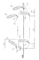
- Explanatory drawing which shows the flow of the ripping operation
- FIGS. 3A to 3C are diagrams showing a monitor installed in the cab of FIG. 2 and a display screen when setting ripper automatic return control.
- (A)-(c) is a figure which shows the mode selection screen of a ripper automatic return control.
- the bulldozer 1 according to an embodiment of the present invention is a construction machine that performs leveling work on rough terrain, and mainly includes a cab 2, a body frame 3, a blade 4, a ripper device 5, and a traveling device 7, as shown in FIG. I have.
- the cab 2 includes an operator seat (driver's seat) 11 on which a driver (operator) is seated, a lever, a pedal, and instruments for various operations (see FIG. 2).
- a working mechanism such as a blade 4 and a ripper device 5 and a traveling device 7 are attached to the body frame 3, and the cab 2 is placed on the upper portion thereof.
- the blade 4 is provided in front of the vehicle body frame 3 and is a working machine for scraping the ground and carrying the earth and sand, and according to an operation of a blade operation lever 31 described later, a hydraulic cylinder (blade lift cylinder 41, It is driven by a blade tilt cylinder 42).
- the ripper device 5 is provided at the rear of the vehicle body frame (airframe) 3 and pierces a rock or the like with a ripper point 5b attached to the tip of a shank 5a protruding substantially vertically downward, and is cut by a traction force by the traveling device 7. Crush. Similarly to the blade 4, the ripper device 5 is driven by a hydraulic cylinder (a ripper lift cylinder 51 and a ripper tilt cylinder 52) in accordance with an operation of a ripper operation lever (operation lever) 32 described later. A method for controlling the ripping work using the ripper device 5 will be described in detail later.
- the traveling device 7 is capable of traveling on rough terrain by rotating a pair of endless crawler belts 7 a provided at the left and right lower portions of the body frame 3.
- the cab 2 of the present embodiment includes an operator seat 11, a right operation device 20, a left operation device 21, a monitor 35, a control device (detection unit, control unit) 40, and the like. Yes.
- the operator seat 11 is a seat on which a driver who gets on and off the cab 2 sits and performs a driving operation, and is installed so as to be slidable back and forth. Further, the operator seat 11 is installed in a rotatable state in order to improve operability when the driver operates the ripper device 5 or the like while looking back. On the left and right sides of the operator seat 11, operating devices such as various operating levers operated by the driver are installed.
- the right operating device 20 is disposed on the right side of the operator seat 11 when viewed from the driver seated on the operator seat 11. Further, a blade operation lever 31, a ripper operation lever (operation lever) 32, and the like are provided on the upper surface of the right operation device 20.
- the blade operation lever 31 is provided at the foremost part on the upper surface of the right operation device 20 and operates a blade lift cylinder 41 and a blade tilt cylinder 42 (see FIGS. 1 and 3) that drive the blade 4.
- the ripper operating lever 32 is provided adjacent to the rear of the blade operating lever 31 on the upper surface of the right operating device 20, and a ripper lift cylinder 51 and a ripper tilt cylinder 52 for driving the ripper device 5 (see FIGS. 1 and 3).
- the ripper operation lever 32 includes a ripper tilt lever 32a and a ripper lift lever 32b (see FIG. 3).
- the ripper tilt lever 32a is an operating tool for tilting in / out the ripper device 5, and operates the ripper tilt cylinder 52.
- the ripper lift lever 32b is an operating tool for raising / lowering the ripper device 5 and operates the ripper lift cylinder 51.
- the left operating device 21 is disposed on the left side of the operator seat 11 when viewed from the driver seated on the operator seat 11.
- a steering operation lever (steering lever) 33, an armrest 34, and the like are provided on the upper surface of the left operation device 21.
- the steering operation lever 33 is swung in the front-rear direction and the left-right direction when the forward direction of the vehicle body is the front, and a steering operation is performed.
- the steering operation lever 33 includes a shift switch 33a and a steering lever 33b (see FIG. 3).
- the shift switch 33a is an operation tool for switching the speed stage of the transmission, and switches the speed stage according to the traveling speed during forward / reverse travel.
- the steering lever 33b is an operation tool that can swing in four directions, front, back, left, and right.
- the steering lever 33b moves forward when it swings forward, moves backward when it swings backward, turns left when it swings left, and turns right
- the direction of travel of the bulldozer 1 is controlled so that it turns right when it is swung.
- the armrest 34 has a bank portion at the left end, and supports the weight of the driver when the center of gravity moves to the left side at the bank portion.
- the monitor 35 is a touch panel type display device arranged on the front side of the operator seat 11, and has an operation panel 35a and touch keys 35b (see FIG. 5A) as shown in FIG. Yes.
- the monitor 35 receives various setting inputs related to the operation of the bulldozer 1 by the operator, and also performs setting inputs related to control of ripping work using the ripper device 5 described later.
- the control device 40 is mounted inside the monitor 35, and controls the operation of the bulldozer 1 during travel and various operations. Further, as shown in FIG. 3, the control device 40 includes a ripper operation lever 32, a steering operation lever 33, a hydraulic pump 36, a hydraulic sensor 36a, a main valve 37, a timer 39, a blade lift cylinder 41, a blade tilt cylinder 42, It is connected to the ripper lift cylinder 51, the hydraulic sensor 51a, the ripper tilt cylinder 52, and the hydraulic sensor 52a, and transmits / receives various signals to / from them.
- control device 40 supplies the discharge amount of the hydraulic pump 36 and the supply from the hydraulic pump 36 in the hydraulic circuit configured in the bulldozer 1 according to the operation of the ripper operation lever 32 and the steering operation lever 33.
- the main valve 37 that determines the supply destination of the pressurized oil
- the hydraulic cylinders 41, 42, 51, 52 that drive the work machine including the blade 4 and the ripper device 5 are operated.
- the ripper automatic return control during the ripping operation by the control device 40 will be described in detail later.
- the operator operates the ripper tilt lever 32a to tilt back the shank 5a, and in this state, grounds the ripper point 5b at the ripping start point. Then, the operator operates the ripper lift lever 32 b to lift the rear part of the bulldozer 1 by the ripper lift cylinder 51.
- the operator depresses the deceleration pedal installed in the cab 2 to reduce the engine speed, and operates the shift switch 33a to set the speed stage to F1. Then, the operator operates the ripper tilt lever 32a to penetrate the ripper point 5b to a desired depth in the ground.
- the engine speed is set to MAX and the bulldozer 1 is advanced by operating the steering lever 33b to perform excavation work. At this time, the operator performs ripping work while operating the ripper tilt lever 32a to tilt the shank 5a.
- the operator advances the bulldozer 1 to a desired position and finishes the ripping operation, the operator operates the ripper lift lever 32b to extract the shank 5a from the bedrock while the bulldozer 1 is moving forward. Thereafter, the operator operates the steering lever 33b to move the bulldozer 1 backward.
- the ripper tilt lever 32a While the bulldozer 1 is moved backward, the operator operates the ripper tilt lever 32a to tilt back the shank 5a.
- the operator holds the ripper operation lever 32 with the right hand and operates the ripper device 5 with the left hand in the cab 2 shown in FIG.
- the front and back of the bulldozer 1 are visually checked while holding the back and forth.
- the operations (4) and (5) described above need to be performed every time as a preparatory work until the next ripping work is performed after the ripping work for one row is performed. These operations require a plurality of operations to be performed at the same time while confirming before and after, so that the operation burden on the operator is large.
- the cab 2 of the bulldozer 1 shown in FIG. 2 is provided with a ripper operation lever 32 on the right side of the operator seat 11 on which the operator sits and a steering operation lever 33 on the left side. It is necessary to make preparations until the next ripping work is performed by visually checking the front and rear while performing separate operations, and the operation burden is very large.
- the ripping return automatic control is set according to the following procedure. That is, when carrying out the ripper automatic return control (ripper auto return), as shown in FIG. 5A, first, the operation panel 35a and the touch key 35b of the monitor 35 provided in the cab 2 are used. Set up. Specifically, when the operator keys on the cab 2, as shown in FIG. 5B, a normal screen 61 is displayed on the operation panel 35a and a touch key screen 62 is displayed on the touch keys 35b.
- the automatic return control starts in the function off state, and the automatic control function display unit 61a in the upper right of the screen displays in a color indicating the function off state (for example, the same blue as the background color of the normal screen 61). Is done.
- the automatic control function display at the upper right of the normal screen 61 is displayed as shown in FIG.
- the part 61a changes to a color indicating function on (for example, green).
- the automatic control function display unit 61a changes to a color (for example, yellow) indicating that the automatic control operation is in progress when the predetermined condition described below is satisfied and the ripper automatic return control is started. Thereby, the operator can recognize that the automatic return control is operating.
- control (first mode) for automating only the operation (lift operation) described above (4), and the operations (4) and (5) described above are independently operated ( Control (automatic operation (second mode) for automatic lift / tilt operation) and control (third mode) for automating operation (4) and (5) described above to operate (lift / tilt interlock operation).
- Three modes are provided.
- the operator selects these three modes in the following procedure. That is, as shown in FIG. 6A, when the operator presses the mode selection button 62b on the touch key screen 62 while the normal screen 61 is displayed on the monitor 35, as shown in FIG. 6B.
- the mode selection screen 63 is displayed on the monitor 35.
- FIG. 6B when the operator selects the ripper auto return button 63a in the mode selection screen 63 and presses the selection button 63b, as shown in FIG.
- An automatic control mode selection screen 64 is displayed on the selection screen 63.
- this automatic control mode selection screen 64 As shown in FIG. 6C, there are four functions OFF button 64a, lift only selection button 64b, lift / tilt independent operation selection button 64c, lift / tilt interlock operation selection button 64d. Two choices are displayed. Therefore, the operator can select the desired operation to be automated, select the desired mode by pressing the selection button 63b, and cause the control device 40 to execute the automatic ripper return control.
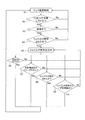
- ⁇ Flow of ripper automatic return control> In the control device 40 mounted on the bulldozer 1 of the present embodiment, when the setting of the above-described automatic return control is completed, when all of the following predetermined conditions (steps S2 to S4) are satisfied, the normal control is changed to the ripper. Switch to automatic return control. On the other hand, after the automatic ripper return control is started, when any one of the following predetermined conditions (steps S6 to S9) is satisfied, the automatic ripper return control is switched to the normal control.
- step S2 it is determined whether or not the ripping operation is being performed. If the ripping operation is being performed, the process proceeds to step S3. Specifically, the determination as to whether or not the ripping operation is in progress is made by determining whether the ripper device 5 has been lowered or tilted in while the bulldozer 1 is being moved forward, or when the bulldozer 1 is stopped. Depending on whether or not there has been a lowering operation. Thereby, for example, it is possible to prevent the automatic ripper return control from being erroneously performed during the earthing work by the blade 4.
- step S3 it is determined whether the bulldozer 1 is moving backward. If the bulldozer 1 is moving backward, the process proceeds to step S4. Here, it is confirmed that the ripping operation is completed and the bulldozer 1 is moving backward.
- step S4 it is determined whether or not the operator has performed a lift (lift) operation with the ripper operation lever 32. If the lift operation has been performed, the process proceeds to step S5. Here, the presence or absence of the ripper raising operation can be detected by the position of the ripper operation lever 32.
- step S5 since the conditions for completing the ripping work and starting the automatic return control in steps S2 to S4 are satisfied, the control device 40 outputs a raising command for the ripper device 5 to raise the ripper device 5. Perform the operation automatically. That is, in this embodiment, when the operator performs a lifting operation with the ripper operation lever 32 even for a moment in a state where the ripping operation is completed in steps S2 and S3, the operator can release the ripper operation lever 32 and then release the hand. The raising operation of the ripper device 5 is automatically continued.
- the operator can automatically perform the subsequent raising operation simply by raising the ripper operation lever 32, as in the normal control, as a trigger for starting the automatic ripper return control. Therefore, the operator can move the bulldozer 1 to the point at which the next ripping operation is started by concentrating on the operation of the steering operation lever 33 when moving backward. As a result, it is possible to reduce the operational burden on the operator by automating some operations after completion of the ripping work while performing the same operation as the normal ripping work without pressing a specific button or the like. it can.
- step S6 it is determined whether or not the bulldozer 1 is moving forward or stopped. This is because when the operator operates the steering operation lever 33 to detect that the bulldozer 1 is going to move backward from the state where the bulldozer 1 is moved backward, the situation where the operator is about to enter the next ripping operation is recognized. This is to cancel the automatic return control.
- step S7 it is determined whether or not the working machine hydraulic pressure is relieved in the hydraulic circuit. This is to stop and interrupt the ripper automatic return control by detecting that the ripper device 5 is fully raised, turning operation, and blade 4 operation.
- the hydraulic pressure sensor 36a that detects the discharge pressure of the hydraulic pump 36
- the hydraulic pressure sensor 51a that detects the discharge pressure to the ripper lift cylinder 51
- the discharge pressure to the ripper tilt cylinder 52 are detected. This is performed based on the detection result in the hydraulic sensor 52a.
- step S8 it is determined whether or not the ripper device 5 has been lowered. That is, when the lowering operation is performed on the ripper operation lever 32, it is assumed that the operator is about to start the next ripping operation, and thus the automatic ripper return control is canceled. This determination may be detected by the lever position of the ripper operation lever 32. It should be noted that automatic control can be effectively canceled by detecting an operation in the opposite direction to the movement of the ripper device 5 by automatic control and giving priority to manual operation of the operator over automatic control. .
- step S9 it is determined by the output from the timer 39 whether or not a predetermined time has elapsed since the output of the ripper raising command from the control device 40.
- This is a release condition set in consideration of safety, assuming that the release is not properly performed according to the release conditions of steps S6 to S8 after the automatic ripper return control is started.
- the ripper automatic return control is started, if any one of the release conditions in steps S6 to S9 is satisfied, the ripper automatic return control is canceled and the normal control is started. And switch.
- step S11 the routine proceeds from the state of the normal ripper control to step S12.
- step S12 it is determined whether or not the ripping operation is in progress. If the ripping operation is in progress, the process proceeds to step S13. Otherwise, the process returns to step S11. Specifically, the determination as to whether or not the ripping operation is in progress is made by determining whether the ripper device 5 has been lowered or tilted in while the bulldozer 1 is being moved forward, or when the bulldozer 1 is stopped. Depending on whether or not there has been a lowering operation. Thereby, for example, it is possible to avoid that the automatic ripper return control is erroneously performed during the earthing work by the blade 4.
- step S13 it is determined whether the bulldozer 1 is moving backward. If the bulldozer 1 is moving backward, the process proceeds to step S14. Here, it is confirmed that the ripping operation is completed and the bulldozer 1 is moving backward.
- step S14 it is determined whether or not the operator has performed a tilt back operation with the ripper operation lever 32. If the tilt back operation has been performed, the process proceeds to step S15. Here, the presence / absence of the tilt back operation can be detected based on the operation status of the ripper operation lever 32 (the ripper tilt lever 32a).
- step S15 since the conditions for completing the ripping operation and starting the automatic return control in steps S12 to S14 are satisfied, the control device 40 outputs the tilt back command of the ripper device 5 to The tilt back operation is performed automatically. That is, in this embodiment, when the operator performs a tilt back operation with the ripper operation lever 32 even for a moment in a state where the ripping work is completed in steps S12 and S13, the hand is released from the ripper operation lever 32 after that. However, the tilt back operation of the ripper device 5 is automatically continued.
- the operator can automatically perform the subsequent tilt back operation only by performing the tilt back operation of the ripper operation lever 32 as in the normal control. . Therefore, the operator can move the bulldozer 1 to the point at which the next ripping operation is started by concentrating on the operation of the steering operation lever 33 when moving backward. As a result, it is possible to reduce the operational burden on the operator by automating some operations after completion of the ripping work while performing the same operation as the normal ripping work without pressing a specific button or the like. it can.
- step S16 it is determined whether or not the bulldozer 1 is moving forward or stopped. This is because when the operator operates the steering operation lever 33 to detect that the bulldozer 1 is going to move backward from the state where the bulldozer 1 is moved backward, the situation where the operator is about to enter the next ripping operation is recognized. This is to cancel the automatic return control.
- step S17 it is determined whether the working machine hydraulic pressure is relieved in the hydraulic circuit. This is to stop and interrupt the ripper automatic return control by detecting that the ripper device 5 is fully raised, turning operation, and blade 4 operation.
- step S18 it is determined whether or not the tilt-in operation of the ripper device 5 has been performed. That is, when the tilt-in operation is performed at the ripper operation lever 32, it is assumed that the operator is about to start the next ripping operation, so the automatic ripper return control is canceled. This determination may be detected by the lever position of the ripper operation lever 32. It should be noted that automatic control can be effectively canceled by detecting an operation in the opposite direction to the movement of the ripper device 5 by automatic control and giving priority to manual operation of the operator over automatic control. .
- step S19 it is determined by the output from the timer 39 whether or not a predetermined time has elapsed since the tilt back command was output from the control device 40.
- This is a release condition set in consideration of safety, assuming that the release is not properly performed by the release conditions in steps S16 to S18 after the automatic ripper return control is started.
- the ripper automatic return control is started, if any one of the release conditions in steps S16 to S19 is satisfied, the ripper automatic return control is canceled and the normal control is started. And switch.
- steps S1 to S9 are the same as the flow of the automatic foot control shown in FIG. That is, when the mode for performing lift / tilt interlocking automatic control (third mode) is set, it is determined whether or not the conditions of steps S2, S3, and S4 are satisfied in order from the normal control state of step S1. If the above condition is satisfied, a lifter raising command is output from the control device 40 in step S5 to automatically perform the lift raising operation.
- step S15 a tilt back command is output from the control device 40, and automatic tilt control is started. That is, in this mode, the tilt automatic control is started on the condition that the lift automatic control is canceled without determining various conditions (steps S12 to S14 in FIG. 8) for performing the tilt back automatic control. .
- the tilt back is automatically performed until the condition for canceling the automatic tilt control is satisfied, and then the control returns to the normal control.
- the operator can select and execute three modes according to his / her preference.
- the automatic tilt control is described with an example in which the automatic tilt / tilt independent operation control (second mode) and the lift / tilt interlock operation control (third mode) are selected.
- second mode automatic tilt / tilt independent operation control
- third mode lift / tilt interlock operation control
- present invention is not limited to this.
- automatic tilt control may also be selectable on the setting screen.
- the bulldozer of the present invention is equipped with a ripper device because the operator's operation burden during ripping work can be greatly reduced compared to the conventional one without pressing down a specific operation button or the like. Widely applicable to work vehicles.
Landscapes
- Engineering & Computer Science (AREA)
- Mining & Mineral Resources (AREA)
- Civil Engineering (AREA)
- General Engineering & Computer Science (AREA)
- Structural Engineering (AREA)
- Mechanical Engineering (AREA)
- Operation Control Of Excavators (AREA)
Abstract
Description
例えば、特許文献1には、このようなリッパ装置のリッピング作業を自動的に制御する装置として、オペレータによって押下されるとリッパ装置を所定の位置まで自動的に上昇させるオートリターンボタンを設けた装置が開示されている。
すなわち、上記公報に開示されたリッパ装置の駆動制御装置では、オペレータが自動制御を実施するためにはオートリターンボタンを押下する必要があるため、リッピング作業における通常の操作以外の操作を伴う。このため、オペレータとしては、通常のリッピング作業時の操作に新たな操作を加える必要があり、従来と同じ感覚でリッピング作業を行うことができないという問題がある。
(課題を解決するための手段)
第1の発明に係るブルドーザは、機体と走行装置とを備えるブルドーザであって、リッパ装置と、操作レバーと、操向操作レバーと、制御部と、を備えている。リッパ装置は、機体の後部に取り付けられており、リッピング作業を行う。操作レバーは、リッパ装置を操作するために設けられている。操向操作レバーは、走行装置による走行を操作するために設けられている。制御部は、操作レバーと操向操作レバーの操作によりリッピング作業が終了したことを検知すると、リッパ装置を地中から引き上げる第1制御と、リッパ装置をチルトバックさせる第2制御と、を実行する。
すなわち、本発明のブルドーザでは、例えば、リッパ装置が地中から引き上げられた等、リッピング作業の終了を検知した場合には、その後で再度リッピング作業を開始するまでに行われる一定の操作について、自動制御を行う。
通常、このようなブルドーザによるリッピング作業では、リッパ装置の先端(リッパポイント)を接地させて機体後部を持ち上げた状態で前進させることで、リッパ装置を地中の所定の深さまで貫入させ、そのまま前進することで岩盤や硬い土等の掘削作業を行う。そして、このようなリッピング作業では、掘削作業を行ったラインに沿って何度もリッピング作業を行うケースが多い。この場合、ブルドーザのオペレータは、リッパ操作レバーを操作しながらリッピング作業を行い、リッピング作業終了後には次のリッピング作業の準備のための操作を繰り返し行う必要がある。さらに、リッピング作業を行う際には、リッパ操作レバーの操作をブルドーザの操向を行うステアリングレバーの操作と連動させて2つの操作レバーを上手く操作する必要があるため、オペレータの操作負担が大きいという問題がある。
そこで、本発明のブルドーザでは、リッピング作業を繰り返し行う際のオペレータの操作負担を軽減するために、リッピング作業が終了したことを検知して、次のリッピング作業の準備を行うまでの一定の操作(リッパ装置の持ち上げおよびリッパ装置のチルトバック)の全部あるいは一部を自動化するように制御を行う。
ここでは、上記開始条件を満たした場合に、リッパ装置を地中から引き上げる第1制御を実行する。
これにより、オペレータはリッピング作業を終えようとする際に操作レバーを一時的に上げ側に操作するだけで、ブルドーザがその後も自動的に上げ操作を継続して実行する。この結果、オペレータは、通常のリッピング作業時の操作を繰り返すだけで、ブルドーザを後進させる操作の方に集中することができるため、従来よりも操作負担を軽減することができる。
すなわち、オペレータによってリッパ装置の操作レバーのチルトバック操作がされると、オペレータがその後で操作レバーを離しても、第2制御が実行されることで、自動的にリッパ装置のチルトバック操作が継続して実行される。
・ブルドーザが前進、あるいは停止していること、
・ブルドーザの油圧回路において作業機油圧が所定のリリーフ圧以上になっていること、
・リッパ装置の操作レバーによって下げ操作されたこと、
・リッパ装置の上げ操作から所定時間以上経過したこと、
のいずれか1つが検知されると、第1制御を解除する。
ここで、上記4つの条件のうち、ブルドーザの前進は、例えば、ステアリングレバーの操作状態に基づいて検知する。また、油圧回路における作業機油圧が所定のリリーフ圧以上になっていることは、例えば、リフトシリンダやチルトシリンダ等の油圧に基づいて検知する。さらに、リッパ装置の操作レバーの下げ操作については、例えば、操作レバーの操作状態に基づいて検知する。リッパ装置の上げ操作から所定時間が経過したことは、例えば、操作レバーの上げ操作を検出して時間を計測するタイマによって検知する。
・ブルドーザが前進、あるいは停止していること、
・ブルドーザの油圧回路において作業機油圧が所定のリリーフ圧以上になっていること、
・リッパ装置の操作レバーによってチルトイン操作されたこと、
・リッパ装置のチルトバック操作から所定時間以上経過したこと、
のいずれか1つが検知されると、第2制御を解除する。
ここで、上記4つの条件のうち、ブルドーザの前進は、例えば、ステアリングレバーの操作状態に基づいて検知する。また、油圧回路における作業機油圧が所定のリリーフ圧以上になっていることは、例えば、リフトシリンダやチルトシリンダ等の油圧に基づいて検知する。さらに、リッパ装置の操作レバーのチルトバック操作については、例えば、操作レバーの操作状態に基づいて検知する。リッパ装置のチルトバック操作から所定時間が経過したことは、例えば、操作レバーのチルトバック操作を検出して時間を計測するタイマによって検知する。
ここでは、所定の条件を満たした場合には、第1・第2制御のうち一方だけを実行するモード(第1モード)と、両方を独立して実行するモード(第2モード)と、両方を連動させて実行するモード(第3モード)と、をオペレータが選択可能である。
これにより、オペレータは、自動化したい操作だけを選択することができるため、オペレータの好みに応じて、効果的にオペレータの操作負担を軽減することができる。
[ブルドーザ1全体の構成]
本実施形態に係るブルドーザ1は、不整地において整地作業を行う建設機械であって、図1に示すように、主として、キャブ2、車体フレーム3、ブレード4、リッパ装置5、および走行装置7を備えている。
車体フレーム3は、ブレード4やリッパ装置5等の作業機構および走行装置7が取り付けられており、その上部にはキャブ2が載置されている。
ブレード4は、車体フレーム3の前方に設けられており、地面を削り取って土砂を押し運ぶための作業機であって、後述するブレード操作レバー31の操作に応じて油圧シリンダ(ブレードリフトシリンダ41、ブレードチルトシリンダ42)によって駆動される。
走行装置7は、車体フレーム3の左右下部にそれぞれ設けられた一対の無端状の履帯7aを回転させることで不整地における走行を可能としている。
本実施形態のキャブ2は、図2に示すように、内部に、オペレータシート11、右側操作装置20、左側操作装置21、モニタ35および制御装置(検知部、制御部)40等を搭載している。
ブレード操作レバー31は、右側操作装置20の上面における最前部に設けられており、ブレード4を駆動するブレードリフトシリンダ41、ブレードチルトシリンダ42(図1,3参照)を動作させる。
操向操作レバー33は、車体の前進方向を前方とした場合の前後方向および左右方向において揺動され、ステアリング操作がなされる。また、操向操作レバー33は、シフトスイッチ33a、ステアリングレバー33b(図3参照)を有している。シフトスイッチ33aは、トランスミッションの速度段を切り換える操作具であって、前進・後進時における走行速度に応じて速度段を切り換える。ステアリングレバー33bは、前後左右の四方向に揺動可能な操作具であって、前方向に揺動させると前進、後方向に揺動させると後進、左方向に揺動させると左折、右方向に揺動させると右折するように、ブルドーザ1の走行方向をコントロールする。
モニタ35は、オペレータシート11の正面側に配置されたタッチパネル式の表示装置であって、図2に示すように、操作パネル35aとタッチキー35b(図5(a)参照)とを有している。そして、モニタ35は、オペレータによってブルドーザ1の操作に関する各種設定入力が行われるとともに、後述するリッパ装置5を用いたリッピング作業の制御に関する設定入力も行われる。
ここで、ブルドーザ1のリッパ装置5を用いたリッピング作業の流れについて、図4を用いて説明すれば以下の通りである。
すなわち、リッパ装置5を用いた一般的なリッピング作業では、オペレータは、図4に示すような手順で各操作を行いながらリッピング作業を行う。なお、以下で説明する(1)~(6)は、図4に示す(1)~(6)における操作に対応している。また、以下の説明において、チルトインとは、シャンク5bを図4における時計回り(リッパポイント5bの指す方向)に回動させることを意味し、チルトバックとは、その逆方向に回動させることを意味している。
(1)オペレータは、リッパチルトレバー32aを操作してシャンク5aをチルトバックさせ、この状態でリッピング開始点にリッパポイント5bを接地させる。そして、オペレータは、リッパリフトレバー32bを操作して、リッパリフトシリンダ51によってブルドーザ1の機体後部を持ち上げる。
(2)オペレータは、キャブ2内に設置された減速ペダルを踏み込んでエンジン回転数を落とし、シフトスイッチ33aを操作して速度段をF1とする。そして、オペレータは、リッパチルトレバー32aを操作して、リッパポイント5bを地中の所望の深さまで貫入させる。
(3)オペレータは、リッパポイント5bを所望の深さまで貫入させると、エンジン回転数をMAXとし、ステアリングレバー33bを操作してブルドーザ1を前進させることで掘削作業を行う。このとき、オペレータは、リッパチルトレバー32aを操作してシャンク5aをチルトさせながらリッピング作業を行う。
(4)オペレータは、ブルドーザ1を所望の位置まで前進させてリッピング作業が終了すると、リッパリフトレバー32bを操作してブルドーザ1が前進している間にシャンク5aを岩盤から抜き取る。その後、オペレータは、ステアリングレバー33bを操作してブルドーザ1を後進させる。
(5)オペレータは、ブルドーザ1を後進させている間に、リッパチルトレバー32aを操作して、シャンク5aをチルトバックさせる。
(6)オペレータは、ブルドーザ1を次のリッピング開始点付近まで後進させると、リッパリフトレバー32bを操作して、リッパポイント5bがリッピング開始点に接地するまでシャンク5aを下げていく。以下、(1)~(6)の操作を繰り返し行う。
ここで、上記(4)、(5)の操作は、一列分のリッピング作業を実施した後、次のリッピング作業を行うまでの準備作業として毎回実施する必要がある。そして、これらの操作は、前後確認をしながら複数の操作を同時に行う必要があるため、オペレータの操作負担が大きい。
本実施形態では、以上のようなリッピング作業時におけるオペレータの操作負担を軽減するために、以下のような手順によりリッピング復帰自動制御の設定を行う。
すなわち、リッパ自動復帰制御(リッパオートリターン)を実施する際には、図5(a)に示すように、まず、キャブ2内に設けられたモニタ35の操作パネル35aおよびタッチキー35bを用いて設定を行う。
具体的には、オペレータがキャブ2内においてキーオンすると、図5(b)に示すように、操作パネル35aに通常画面61、タッチキー35bにタッチキー画面62が表示される。このキーオン直後の通常画面61では、自動復帰制御は機能オフ状態で立ち上がり、画面右上の自動制御機能表示部61aは機能オフ状態を示す色(例えば、通常画面61の背景色と同じ青色)で表示される。
本実施形態では、このリッパ自動復帰制御として、上述した(4)の動作(リフト作動)のみ自動化する制御(第1モード)、上述した(4)、(5)の動作を独立して作動(リフト/チルト独立作動)させるように自動化する制御(第2モード)、上述した(4)、(5)の動作を作動(リフト/チルト連動作動)させるように自動化する制御(第3モード)という、3つのモードを設けている。
すなわち、図6(a)に示すように、モニタ35に通常画面61が表示されている状態において、オペレータがタッチキー画面62のモード選択ボタン62bを押下すると、図6(b)に示すように、モニタ35にモード選択画面63が表示される。
次に、図6(b)に示すように、オペレータが、モード選択画面63中のリッパオートリターンボタン63aを選択して、選択ボタン63bを押下すると、図6(c)に示すように、モード選択画面63上に自動制御モード選択画面64が表示される。
よって、オペレータは、自動化したい作業を選択して、選択ボタン63bを押下することで所望のモードを選択して、制御装置40にリッパ自動復帰制御を実行させることができる。
本実施形態のブルドーザ1に搭載された制御装置40では、上述した自動復帰制御の設定が完了すると、以下のような所定の条件(ステップS2~S4)を全て満たした場合に、通常制御からリッパ自動復帰制御に切り換える。一方、リッパ自動復帰制御が開始された後には、以下のような所定の条件(ステップS6~S9)のいずれか1つを満たした場合に、リッパ自動復帰制御から通常制御へ切り換える。
ここでは、まず、上述したリッピング作業完了後の動作のうち、図4に示す(4)のリッパ装置5のリフト動作を自動化する制御について説明する。
すなわち、上述したモード設定によって、自動制御モード選択画面64においてリフトのみ選択ボタン64bが選択されると、図7に示すように、ステップS1において、リッパ通常制御の状態からステップS2に移行する。
ステップS4では、オペレータによって、リッパ操作レバー32で上げ(リフト)操作がされたか否かを判定し、上げ操作された場合にはステップS5へ進む。ここで、リッパ上げ操作の有無は、リッパ操作レバー32の位置によって検出することができる。
すなわち、本実施形態では、ステップS2,S3においてリッピング作業が完了して後進している状態において、オペレータが一瞬でもリッパ操作レバー32で上げ操作すると、その後、リッパ操作レバー32から手を離しても、自動的にリッパ装置5の上げ操作は継続して行われる。
ステップS6では、ブルドーザ1が前進中、あるいは停止中であるか否かを判定する。これは、オペレータが操向操作レバー33を操作してブルドーザ1を後進させている状態から前進させようとしていることを検知することで、次のリッピング作業に入ろうとしている状況を認識して、リッパ自動復帰制御を解除するためである。
本実施形態では、以上のように、リッパ自動復帰制御が開始されると、ステップS6~S9のいずれか1つの解除条件でも満たした場合には、リッパ自動復帰制御を解除して、通常制御へと切り換える。
次に、上述したリッピング作業完了後の動作のうち、図4に示す(5)のリッパ装置5のチルト動作を自動化する制御について説明する。
すなわち、上述したモード設定によって、自動制御モード選択画面64においてリフト/チルト独立作動選択ボタン64cが選択されると、図7に示すリフト自動制御とは独立して、図8に示すチルト自動制御が実施される。
具体的には、図8に示すように、ステップS11において、リッパ通常制御の状態からステップS12に移行する。
ステップS14では、オペレータによって、リッパ操作レバー32でチルトバック操作がされたか否かを判定し、チルトバック操作された場合にはステップS15へ進む。ここで、チルトバック操作の有無は、リッパ操作レバー32(リッパチルトレバー32a)の操作状況によって検出することができる。
すなわち、本実施形態では、ステップS12,S13においてリッピング作業が完了して後進している状態において、オペレータが一瞬でもリッパ操作レバー32でチルトバック操作すると、その後、リッパ操作レバー32から手を離しても、自動的にリッパ装置5のチルトバック動作は継続して行われる。
ステップS16では、ブルドーザ1が前進中、あるいは停止中であるか否かを判定する。これは、オペレータが操向操作レバー33を操作してブルドーザ1を後進させている状態から前進させようとしていることを検知することで、次のリッピング作業に入ろうとしている状況を認識して、リッパ自動復帰制御を解除するためである。
ステップS18では、リッパ装置5のチルトイン操作がされたか否かを判定する。つまり、リッパ操作レバー32においてチルトイン操作がされたということは、オペレータが次のリッピング作業を開始しようとしていることが想定されるため、リッパ自動復帰制御を解除する。この判定については、リッパ操作レバー32のレバーの位置によって検出すればよい。なお、このように自動制御によるリッパ装置5の動きとは逆方向への操作を検知して、オペレータの手動操作を自動制御よりも優先させることで、効果的に自動制御を解除することができる。
本実施形態では、以上のように、リッパ自動復帰制御が開始されると、ステップS16~S19のいずれか1つの解除条件でも満たした場合には、リッパ自動復帰制御を解除して、通常制御へと切り換える。
なお、図6(c)に示す自動制御モード選択画面64においてリフト/チルト独立作動選択ボタン64cが選択されると、上述したリフト自動制御とは独立して、このチルト自動制御も並行して進められる。
次に、上述したリッピング作業完了後の動作のうち、図4に示す(4)および(5)のリッパ装置5のリフト動作およびチルト動作を連動させて自動化する制御について説明する。
すなわち、上述したモード設定によって、自動制御モード選択画面64においてリフト/チルト連動作動選択ボタン64dが選択されると、上記リフト自動制御とチルト自動制御とを連動させるように制御が行われる。
つまり、リフト/チルト連動自動制御を実施するモード(第3モード)が設定されると、ステップS1の通常制御状態から順に、ステップS2,S3,S4の条件を満たすか否かを判定し、全ての条件を満たした場合には、ステップS5において制御装置40からリッパ上げ指令を出力してリフト上げ動作を自動的に行う。
以上のように、本実施形態では、オペレータが自身の好みに合わせて3つのモードを選択して実行させることができる。
以上、本発明の一実施形態について説明したが、本発明は上記実施形態に限定されるものではなく、発明の要旨を逸脱しない範囲で種々の変更が可能である。
上記実施形態では、リッパ自動復帰制御の開始条件および解除条件について、それぞれ例を挙げて説明した。しかし、本発明はこれに限定されるものではない。
例えば、開始条件および解除条件として、他の条件を追加してもよいし、上述した開始条件および解除条件の一部を削除して実施してもよい。
上記実施形態では、上記チルト自動制御については、リフト/チルト独立作動制御(第2モード)およびリフト/チルト連動作動制御(第3モード)選択時にのみ、実施される例を挙げて説明した。しかし、本発明はこれに限定されるものではない。
例えば、チルト自動制御についても、設定画面において単一で選択可能となっていてもよい。
2 キャブ
3 車体フレーム
4 ブレード
5 リッパ装置
5a シャンク
5b リッパポイント
7 走行装置
7a 履帯
11 オペレータシート(運転席)
20 右側操作装置
21 左側操作装置
31 ブレード操作レバー
32 リッパ操作レバー(操作レバー)
32a リッパチルトレバー
32b リッパリフトレバー
33 操向操作レバー(ステアリングレバー)
33a シフトスイッチ
33b ステアリングレバー
34 アームレスト
35 モニタ
35a 操作パネル
35b タッチキー
36 油圧ポンプ
36a 油圧センサ
37 メインバルブ
39 タイマ
40 制御装置(検知部、制御部)
41 ブレードリフトシリンダ
42 ブレードチルトシリンダ
51 リッパリフトシリンダ
51a 油圧センサ
52 リッパチルトシリンダ
52a 油圧センサ
61 通常画面
61a 自動制御機能表示部
62 タッチキー画面
62a 自動制御機能ON/OFFボタン
62b モード選択ボタン
63 モード選択画面
63a リッパオートリターンボタン
63b 選択ボタン
64 自動制御モード選択画面
64a 機能オフボタン
64b リフトのみ選択ボタン
64c リフト/チルト独立作動選択ボタン
64d リフト/チルト連動作動選択ボタン
Claims (8)
- 機体と走行装置とを備えるブルドーザであって、
前記機体の後部に取り付けられており、リッピング作業を行うリッパ装置と、
前記リッパ装置を操作するための操作レバーと、
前記走行装置による走行を操作するための操向操作レバーと、
前記操作レバーと前記操向操作レバーの操作により前記リッピング作業が終了したことを検知すると、前記リッパ装置を地中から引き上げる第1制御と、前記リッパ装置をチルトバックさせる第2制御と、を実行する制御部と、
を備えているブルドーザ。 - 前記制御部は、前記第1制御を選択的に実行する第1モードが設定される、
請求項1に記載のブルドーザ。 - 前記制御部は、リッピング作業中に前記操向操作レバーが後進側に操作され、かつ前記リッパ装置の操作レバーによって上げ操作をされたことによりリッピング作業が終了したことが検知されると、前記第1制御を実行する、
請求項1または2に記載のブルドーザ。 - 前記制御部は、前記リッピング作業中に前記操向操作レバーが後進側に操作され、かつ前記リッパ装置の操作レバーによってチルトバック操作されたことが検知されると、前記第2制御を実行する、
請求項1から3のいずれか1項に記載のブルドーザ。 - 前記制御部は、前記ブルドーザの油圧回路において作業機油圧が所定のリリーフ圧以上になっていること、前記検知部において、前記ブルドーザが前進あるいは停止していること、前記リッパ装置の操作レバーによって下げ操作されたこと、前記リッパ装置の上げ操作から所定時間以上経過したこと、のいずれか1つが検知されると、前記第1制御を解除する、
請求項3に記載のブルドーザ。 - 前記制御部は、前記ブルドーザの油圧回路において作業機油圧が所定のリリーフ圧以上になっていること、前記検知部において、前記ブルドーザが前進あるいは停止していること、前記リッパ装置の操作レバーによってチルトイン操作されたこと、前記リッパ装置のチルトバック操作から所定時間以上経過したこと、のいずれか1つが検知されると、前記第2制御を解除する、
請求項4に記載のブルドーザ。 - 前記制御部は、前記第1・第2制御を独立して実行する第2モードと、前記第1・第2制御を連動させて実行する第3モードと、が設定される、
請求項2に記載のブルドーザ。 - ブルドーザの機体の後部に取り付けられたリッパ装置の動きを制御するリッパ装置の駆動制御方法であって、
ブルドーザが前進または停止中に前記リッパ装置が操作される第1ステップと、
ブルドーザが後進にされ前記リッパ装置が上げ操作される第2ステップと、
前記リッパ装置を自動的に上げる第3ステップと、
を備えているリッパ装置の駆動制御方法。
Priority Applications (2)
| Application Number | Priority Date | Filing Date | Title |
|---|---|---|---|
| CN201180003481.6A CN102523748B (zh) | 2010-09-14 | 2011-09-07 | 推土机 |
| US13/392,845 US8616297B2 (en) | 2010-09-14 | 2011-09-07 | Bulldozer including controller that performs automatic control of ripper |
Applications Claiming Priority (2)
| Application Number | Priority Date | Filing Date | Title |
|---|---|---|---|
| JP2010205149A JP5132742B2 (ja) | 2010-09-14 | 2010-09-14 | ブルドーザ |
| JP2010-205149 | 2010-09-14 |
Related Child Applications (2)
| Application Number | Title | Priority Date | Filing Date |
|---|---|---|---|
| US13/392,845 A-371-Of-International US8616297B2 (en) | 2010-09-14 | 2011-09-07 | Bulldozer including controller that performs automatic control of ripper |
| US14/063,082 Division US8788157B2 (en) | 2010-09-14 | 2013-10-25 | Control method for driving a ripper |
Publications (1)
| Publication Number | Publication Date |
|---|---|
| WO2012036045A1 true WO2012036045A1 (ja) | 2012-03-22 |
Family
ID=45831512
Family Applications (1)
| Application Number | Title | Priority Date | Filing Date |
|---|---|---|---|
| PCT/JP2011/070386 Ceased WO2012036045A1 (ja) | 2010-09-14 | 2011-09-07 | ブルドーザ |
Country Status (4)
| Country | Link |
|---|---|
| US (2) | US8616297B2 (ja) |
| JP (1) | JP5132742B2 (ja) |
| CN (1) | CN102523748B (ja) |
| WO (1) | WO2012036045A1 (ja) |
Families Citing this family (25)
| Publication number | Priority date | Publication date | Assignee | Title |
|---|---|---|---|---|
| JP5132742B2 (ja) * | 2010-09-14 | 2013-01-30 | 株式会社小松製作所 | ブルドーザ |
| JP2013071840A (ja) * | 2011-09-29 | 2013-04-22 | Toyota Industries Corp | フォークリフト |
| CN103874804B (zh) * | 2013-03-08 | 2015-11-25 | 株式会社小松制作所 | 推土机及推土铲控制方法 |
| EA024772B1 (ru) * | 2013-03-27 | 2016-10-31 | Куттубек Исаков | Бульдозер-погрузчик с трансформирующимся рабочим органом |
| US9033062B2 (en) * | 2013-07-11 | 2015-05-19 | Caterpillar Inc. | Control system for a machine |
| US9388551B2 (en) * | 2014-02-26 | 2016-07-12 | Caterpillar Inc. | Shift logic for ground ripping machine |
| US9297146B1 (en) | 2014-09-09 | 2016-03-29 | Caterpillar Inc. | Automatic ripping pass detection |
| US9663921B2 (en) | 2015-07-09 | 2017-05-30 | Caterpillar Inc. | System and method for controlling operations of a machine |
| US9481977B1 (en) * | 2015-07-24 | 2016-11-01 | Caterpillar Inc. | System and method for controlling a machine |
| WO2016006716A1 (ja) * | 2015-08-07 | 2016-01-14 | 株式会社小松製作所 | 作業車両 |
| US10640952B2 (en) * | 2016-12-09 | 2020-05-05 | Caterpillar Inc. | System and method for modifying a material movement plan |
| US10633826B2 (en) | 2016-12-22 | 2020-04-28 | Cnh Industrial America Llc | System and method for control of a work vehicle |
| JP6946094B2 (ja) * | 2017-07-18 | 2021-10-06 | 株式会社クボタ | 作業機 |
| CN107313475B (zh) * | 2017-08-15 | 2023-02-21 | 山推工程机械股份有限公司 | 一种推土机松土器控制系统及其控制方法 |
| US11001988B2 (en) * | 2018-06-18 | 2021-05-11 | Caterpillar Inc. | Controlling interlocks based on an interlock configuration |
| JP7039406B2 (ja) * | 2018-07-11 | 2022-03-22 | 株式会社クボタ | 作業車両 |
| US11174967B2 (en) * | 2020-02-28 | 2021-11-16 | Trinity Bay Equipment Holdings, LLC | Ripper shank trailer hitch systems and methods |
| JP7669187B2 (ja) * | 2021-05-19 | 2025-04-28 | 株式会社小松製作所 | 積込機械の制御システム及び制御方法 |
| US12195943B2 (en) | 2021-08-06 | 2025-01-14 | Cnh Industrial America Llc | Shoe control system for a dozer blade assembly |
| JP2023059397A (ja) * | 2021-10-15 | 2023-04-27 | 株式会社小松製作所 | 作業機械のための表示システムおよび表示方法 |
| US12351995B2 (en) | 2022-04-28 | 2025-07-08 | Caterpillar Paving Products Inc. | Auto scratch height for work machines |
| JP2024055024A (ja) * | 2022-10-06 | 2024-04-18 | 日立建機株式会社 | 作業機械 |
| CN115573410B (zh) * | 2022-12-09 | 2023-03-14 | 柳工常州机械有限公司 | 推土机及其控制系统 |
| US12584291B2 (en) | 2023-12-21 | 2026-03-24 | Caterpillar Inc. | Control system for ripper operation |
| US20250207370A1 (en) * | 2023-12-22 | 2025-06-26 | Caterpillar Inc. | Control System for Operating a Mobile Machine with a Ripper |
Citations (3)
| Publication number | Priority date | Publication date | Assignee | Title |
|---|---|---|---|---|
| JPH07197486A (ja) * | 1993-12-28 | 1995-08-01 | Hitachi Constr Mach Co Ltd | 建設機械のブレード制御装置 |
| JPH1088614A (ja) * | 1996-09-05 | 1998-04-07 | Caterpillar Inc | ブルドーザリッパーのオートリターン装置 |
| WO2009075210A1 (ja) * | 2007-12-13 | 2009-06-18 | Komatsu Ltd. | リッパの操作装置 |
Family Cites Families (14)
| Publication number | Priority date | Publication date | Assignee | Title |
|---|---|---|---|---|
| IT1011926B (it) * | 1974-06-06 | 1977-02-10 | Gimac Spa | Dispositivo scarificatore applicabi le a trattori ed a veicoli similari |
| US4044838A (en) * | 1975-04-21 | 1977-08-30 | American Tractor Equipment Corporation | Automatic control for ripper tool |
| US5287280A (en) * | 1987-09-14 | 1994-02-15 | Kabushiki Kaisha Komatsu Seisakusho | Method and apparatus for controlling shoe slip of crawler vehicle |
| JPH0830426B2 (ja) * | 1988-08-23 | 1996-03-27 | 株式会社小松製作所 | シュースリップに基づくエンジン出力制御方法 |
| JP2580351B2 (ja) * | 1989-12-28 | 1997-02-12 | 株式会社小松製作所 | 衝撃リッパの自動制御装置 |
| US5999872A (en) * | 1996-02-15 | 1999-12-07 | Kabushiki Kaisha Kobe Seiko Sho | Control apparatus for hydraulic excavator |
| CN2346659Y (zh) * | 1998-02-26 | 1999-11-03 | 山东山推工程机械股份有限公司 | 履带式推土机 |
| US7635045B2 (en) | 2004-07-30 | 2009-12-22 | Caterpillar Inc. | Machine tool control console |
| US7658234B2 (en) * | 2005-12-09 | 2010-02-09 | Caterpillar Inc. | Ripper operation using force vector and track type tractor using same |
| US7913798B2 (en) * | 2008-03-07 | 2011-03-29 | Deere & Company | Armrest mounted grader control |
| US7793740B2 (en) * | 2008-10-31 | 2010-09-14 | Caterpillar Inc | Ride control for motor graders |
| CN102458968B (zh) * | 2009-06-24 | 2015-02-18 | 株式会社小松制作所 | 作业车辆的悬架装置 |
| JP5132742B2 (ja) * | 2010-09-14 | 2013-01-30 | 株式会社小松製作所 | ブルドーザ |
| US8437926B2 (en) * | 2011-01-06 | 2013-05-07 | Komatsu Ltd. | Control device and pitch angle control method |
-
2010
- 2010-09-14 JP JP2010205149A patent/JP5132742B2/ja active Active
-
2011
- 2011-09-07 CN CN201180003481.6A patent/CN102523748B/zh active Active
- 2011-09-07 US US13/392,845 patent/US8616297B2/en active Active
- 2011-09-07 WO PCT/JP2011/070386 patent/WO2012036045A1/ja not_active Ceased
-
2013
- 2013-10-25 US US14/063,082 patent/US8788157B2/en active Active
Patent Citations (3)
| Publication number | Priority date | Publication date | Assignee | Title |
|---|---|---|---|---|
| JPH07197486A (ja) * | 1993-12-28 | 1995-08-01 | Hitachi Constr Mach Co Ltd | 建設機械のブレード制御装置 |
| JPH1088614A (ja) * | 1996-09-05 | 1998-04-07 | Caterpillar Inc | ブルドーザリッパーのオートリターン装置 |
| WO2009075210A1 (ja) * | 2007-12-13 | 2009-06-18 | Komatsu Ltd. | リッパの操作装置 |
Also Published As
| Publication number | Publication date |
|---|---|
| US20120267128A1 (en) | 2012-10-25 |
| CN102523748A (zh) | 2012-06-27 |
| US20140048294A1 (en) | 2014-02-20 |
| US8788157B2 (en) | 2014-07-22 |
| JP5132742B2 (ja) | 2013-01-30 |
| US8616297B2 (en) | 2013-12-31 |
| JP2012062620A (ja) | 2012-03-29 |
| CN102523748B (zh) | 2015-04-01 |
Similar Documents
| Publication | Publication Date | Title |
|---|---|---|
| JP5132742B2 (ja) | ブルドーザ | |
| JP2012062620A5 (ja) | ||
| JP5700613B1 (ja) | 作業車両及び作業車両の制御方法 | |
| US8831797B2 (en) | Wheel loader | |
| US11408148B2 (en) | Working machine with control device to control operation allowable state and operation restriction state | |
| EP2623679B1 (en) | Work machine display system | |
| US20220267998A1 (en) | Construction machine | |
| KR20000022741A (ko) | 작업기의 각도 제어방법 및 그 제어장치 | |
| EP3584374B1 (en) | Work vehicle | |
| US12404880B2 (en) | Boom control system of work machine | |
| EP2894264B1 (en) | A method of operating a material handling machine | |
| WO2021182285A1 (ja) | 操作ガイド装置 | |
| US9617710B2 (en) | Work vehicle and method for controlling work vehicle | |
| US20120315120A1 (en) | Work machine | |
| CN113047366B (zh) | 挖掘装载机控制方法、装置、系统及挖掘装载机 | |
| WO2021182286A1 (ja) | 操作システム | |
| JP4140940B2 (ja) | 掘削積込機械の作業機制御装置 | |
| US20240084557A1 (en) | Display system of work machine | |
| JP5138526B2 (ja) | 作業車両 | |
| JP2010076614A (ja) | 作業車両 | |
| JP4690352B2 (ja) | 建設機械の走行制御装置 | |
| EP4517009A1 (en) | Work machine control method, work machine control program, work machine control system, and work machine | |
| JP5149756B2 (ja) | 作業車両 | |
| KR102885712B1 (ko) | 건설 기계의 구동 방법 | |
| GB2641046A (en) | Controller, working machine and method |
Legal Events
| Date | Code | Title | Description |
|---|---|---|---|
| WWE | Wipo information: entry into national phase |
Ref document number: 201180003481.6 Country of ref document: CN |
|
| WWE | Wipo information: entry into national phase |
Ref document number: 13392845 Country of ref document: US |
|
| 121 | Ep: the epo has been informed by wipo that ep was designated in this application |
Ref document number: 11825051 Country of ref document: EP Kind code of ref document: A1 |
|
| NENP | Non-entry into the national phase |
Ref country code: DE |
|
| 122 | Ep: pct application non-entry in european phase |
Ref document number: 11825051 Country of ref document: EP Kind code of ref document: A1 |