WO2012035795A1 - ワイヤーハーネス配策構造部 - Google Patents
ワイヤーハーネス配策構造部 Download PDFInfo
- Publication number
- WO2012035795A1 WO2012035795A1 PCT/JP2011/054345 JP2011054345W WO2012035795A1 WO 2012035795 A1 WO2012035795 A1 WO 2012035795A1 JP 2011054345 W JP2011054345 W JP 2011054345W WO 2012035795 A1 WO2012035795 A1 WO 2012035795A1
- Authority
- WO
- WIPO (PCT)
- Prior art keywords
- wire harness
- door
- vehicle body
- exterior member
- guide
- Prior art date
- Legal status (The legal status is an assumption and is not a legal conclusion. Google has not performed a legal analysis and makes no representation as to the accuracy of the status listed.)
- Ceased
Links
Images





Classifications
-
- H—ELECTRICITY
- H02—GENERATION; CONVERSION OR DISTRIBUTION OF ELECTRIC POWER
- H02G—INSTALLATION OF ELECTRIC CABLES OR LINES, OR OF COMBINED OPTICAL AND ELECTRIC CABLES OR LINES
- H02G11/00—Arrangements of electric cables or lines between relatively-movable parts
-
- B—PERFORMING OPERATIONS; TRANSPORTING
- B60—VEHICLES IN GENERAL
- B60R—VEHICLES, VEHICLE FITTINGS, OR VEHICLE PARTS, NOT OTHERWISE PROVIDED FOR
- B60R16/00—Electric or fluid circuits specially adapted for vehicles and not otherwise provided for; Arrangement of elements of electric or fluid circuits specially adapted for vehicles and not otherwise provided for
- B60R16/02—Electric or fluid circuits specially adapted for vehicles and not otherwise provided for; Arrangement of elements of electric or fluid circuits specially adapted for vehicles and not otherwise provided for electric constitutive elements
- B60R16/0207—Wire harnesses
- B60R16/0215—Protecting, fastening and routing means therefor
-
- H—ELECTRICITY
- H02—GENERATION; CONVERSION OR DISTRIBUTION OF ELECTRIC POWER
- H02G—INSTALLATION OF ELECTRIC CABLES OR LINES, OR OF COMBINED OPTICAL AND ELECTRIC CABLES OR LINES
- H02G3/00—Installations of electric cables or lines or protective tubing therefor in or on buildings, equivalent structures or vehicles
- H02G3/02—Details
- H02G3/04—Protective tubing or conduits, e.g. cable ladders or cable troughs
- H02G3/0462—Tubings, i.e. having a closed section
- H02G3/0487—Tubings, i.e. having a closed section with a non-circular cross-section
Definitions
- Patent Document 1 discloses a technique for arranging a wire harness indoors from a weather strip.
- the wire harness arrangement structure of Patent Document 1 includes a housing case that has a hollow portion that winds and houses the wire harness and has an opposing insertion port and outlet. Then, the wire harness is fixed to the insertion port, inserted into the housing case, wound inside the housing case, and then pulled out and inserted through the outlet. Further, the housing case is fixed to the door, and the wire harness pulled out from the housing case is arranged on the vehicle body side and locked by a clamp. Thereby, the winding diameter of the wire harness inserted in the inside of the storage case changes according to the door opening / closing operation, and the wire harness is expanded and contracted.
- an object of the present invention is to make the wire harness routed from the vehicle body to the door more smoothly interlocked with the opening / closing operation of the door.
- the wire harness arrangement structure part which concerns on a 1st aspect is a wire harness arrangement structure part which arranges a wire harness from a vehicle body to a door in a vehicle interior side from a weather strip, Comprising: In the said wire harness and the said wire harness The exterior member to be exteriorized, the one end side portion of the exterior member are fixed, the attachment member attachable to the vehicle body, and can be disposed in the door, and extend from the other end of the exterior member.
- the wire harness routing structure according to the second aspect is the wire harness routing structure according to the first aspect, wherein the mounting member and one end of the guide are displaced in the vertical direction of the vehicle body.
- the one end side portion of the guide portion is formed so as to spread at least toward the mounting member in the vertical direction of the vehicle body.
- the wire harness routing structure according to the third aspect is the wire harness routing structure according to the first or second aspect, provided on one end side of the guide part, and on the outer periphery of the exterior member A flexible soundproof member is further provided for inserting the exterior member so as to come into contact.
- a wire harness routing structure is a wire harness routing structure according to any one of the first to third aspects, and the mounting member is formed on the vehicle body. It has a fitting part which can be fitted by pressing against the hole part from one side, and a positioning part which can position the one end side part of the exterior member.
- the wire harness routing structure according to the fifth aspect is the wire harness routing structure according to any one of the first to fourth aspects, and the exterior member is formed in a flat shape, It is provided in a posture that becomes flat along the vertical direction of the vehicle body.
- the exterior member that is sheathed by the wire harness is guided by the guide portion toward the accommodating portion that absorbs the extra length of the wire harness. Furthermore, the guide part is formed so that the one end side part on the opposite side to the accommodating part spreads toward the one end edge part. For this reason, by guiding the exterior member to the guide portion, the wire harness routed from the vehicle body to the door can be more smoothly interlocked with the opening / closing operation of the door.
- the attachment member and one end portion of the guide portion are provided at positions shifted in the vertical direction of the vehicle body. That is, the wire harness in the exterior member that extends between the mounting member and one end of the guide portion is routed with a step in the vertical direction of the vehicle body, and is not only bent and deformed but also twisted when the door is opened and closed. It also deforms in the direction. Thereby, it can suppress that a load is locally applied with respect to a wire harness.
- one end side part of a guide part is formed so that it may spread at least to the attachment member side among the up-and-down directions of the body, it guides the wire harness arranged by being displaced also in the up-and-down direction more smoothly Thus, the door can be opened and closed more smoothly.
- the flexible soundproof member is provided on one end side of the guide portion, and the exterior member is in contact with the outer peripheral portion of the exterior member extending from the one end portion of the guide portion. Therefore, it is possible to suppress noise generated by rubbing the exterior member that advances and retracts into the door when the door is opened and closed with the door inner panel and the trim.
- an attachment member positions the one end side part of the exterior member covered by a wire harness with a positioning part, and presses it from one side with respect to the hole of a vehicle body Therefore, the wire harness can be easily routed to the vehicle body side.
- the exterior member is formed in a flat shape and is provided in a posture that is flat along the vertical direction of the vehicle body, and therefore, between the door inner panel and the trim. Even in the case of a door with a small space, it can be applied.
- This wire harness routing structure 10 routes the wire harness WH from the vehicle body 2 to the door 6.
- the vehicle body 2 includes an interior member such as an instrument panel 3 formed of a resin in addition to a frame portion formed of a metal member.
- the wire harness WH is configured by appropriately bundling a plurality of electric wires for supplying power or transmitting signals to electric devices such as a power window and a door lock mounted on the door 6 corresponding to the routing route. (See FIGS. 2 and 5).
- electric devices such as a power window and a door lock mounted on the door 6 corresponding to the routing route.
- FIGS. 2 and 5 what is routed from the vehicle body 2 to the door 6 in the wire harness WH is a portion where a plurality of electric wires are bundled together.
- the wire harness WH branches in the door 6 and is connected to various electric equipment.
- the door 6 is connected to the vehicle body 2 by a door hinge 5 so that the doorway of the vehicle body 2 can be opened and closed (see FIGS. 1 and 4).
- a door hinge 5 so that the doorway of the vehicle body 2 can be opened and closed (see FIGS. 1 and 4).
- the door 6 is connected to the vehicle body 2 so as to change its posture around an axis along the vertical direction.
- Waterproof weather strips 2w and 6w are attached to the vehicle body 2 and the door 6 along the peripheral edge of the door 6 or the opening edge of the entrance / exit of the vehicle body 2 (opening edge of the frame 4), respectively. (See FIGS. 1, 2, 4, and 5).
- the weather strips 2w and 6w are formed of rubber or the like that can be kept in a watertight state in the vehicle interior and exterior in close contact with the opening edge of the frame 4 of the vehicle body 2 or the peripheral edge of the door 6 with the door 6 closed. It is a member.
- the wire harness WH is routed between the vehicle body 2 and the door 6 from the weather strips 2w, 6w to the vehicle interior side (see FIGS. 1 and 4).
- the wire harness WH is bridged from the side of the instrument panel 3 of the vehicle body 2 to the front side end of the vehicle body 2 of the front side door and routed between the vehicle body 2 and the door 6.
- the instrument panel 3 does not indicate only a portion that covers the instruments, but includes an interior member (also referred to as a dashboard) in the vicinity thereof (in front of the front row seat).
- a vehicle body side hole 3 h for inserting the wire harness WH into the instrument panel 3 is formed on the side of the instrument panel 3 of the vehicle body 2.
- the vehicle body side hole 3h is formed on the vehicle interior side with respect to the weather strips 2w and 6w.
- the door 6 has a door inner panel 7 made of a metal material and a trim 8 as an interior member made of a resin material or the like.
- a door-side recess for inserting the wire harness WH into the door 6 is formed in one or both of the door inner panel 7 and the trim 8 at a portion of the door 6 on the front end side of the vehicle body 2.
- door side recesses 7h, 8h are formed in both the door inner panel 7 and the trim 8.
- the wire harness WH is bridged from the vehicle body 2 side through the vehicle body side hole 3h to the door 6 side, and routed between the door inner panel 7 and the trim 8 through the door side recesses 7h and 8h (FIG. 3, 6 and FIG. 10), and is branched and connected to various electric devices (see FIG. 2 and FIG. 5).
- the portion of the vehicle body 2 in which the vehicle body side hole 3h is formed and the portion of the door 6 in which the door side recesses 7h and 8h are formed face the vehicle body 2 or the door 6 with the door 6 closed. It is difficult to see from the passenger compartment.
- the wire harness arrangement structure part 10 is provided with the exterior member 20, the attachment member 30, the accommodating part 40, the guide part 50, and the flexible sound-insulation member 60 (refer FIG. 1, FIG. 4).
- a portion of the wire harness WH that extends from the vehicle body 2 to the door 6 is provided with an exterior member 20.
- the exterior member 20 is a member that protects the wire harness WH from the outside in a state where the wire harness WH is inserted, and supports the wire harness WH while suppressing dripping between the vehicle body 2 and the door 6.
- the exterior member 20 is formed in a cylindrical shape and protects the wire harness WH while it is inserted. More specifically, the exterior member 20 is a member having flexibility so as to bend between the vehicle body 2 and the door 6 corresponding to the opening / closing operation of the door 6.
- the exterior member 20 is a corrugated tube manufactured by extrusion molding and vacuum molding or blow molding of an elastomer such as synthetic resin or synthetic rubber.
- the exterior member 20 is formed in a flat shape (for example, a flat shape such as a substantially elliptical shape or a substantially rectangular shape in cross section).
- the wire harness WH itself is also bundled in a flat shape, and the exterior member 20 is good to be formed in the flat shape corresponding to the external shape of the wire harness WH.
- the exterior member 20 is not limited to the corrugated tube.
- a protector manufactured in a rectangular tube shape or a cylindrical shape by injection molding resin with a mold may be used as the exterior member.
- one end of the exterior member is attached to the vehicle body side via a hinge so that the exterior member can be operated corresponding to the opening / closing operation of the door 6.
- the exterior member 20 has one end side portion fixed to the vehicle body 2 via the attachment member 30 and the other end portion being a free end.
- the attachment member 30 is a member that attaches one end of the exterior member 20 that is sheathed to the wire harness WH to the vehicle body 2 so as to route the wire harness WH toward the vehicle body 2 side.
- the attachment member 30 is configured such that one end side portion of the exterior member 20 is fixed and can be attached to the vehicle body 2.
- the attachment member 30 is attached to the vehicle body side hole 3h for insertion of the wire harness WH formed on the side of the instrument panel 3. More specifically, the attachment member 30 is configured to be attachable by pressing from one side (here, the door side) against the vehicle body side hole 3h.
- the mounting member 30 includes a fitting portion 32 that can be fitted into the vehicle body side hole 3h, and a positioning portion 38 that can position one end side portion of the exterior member 20 (FIGS. 7 and 8). reference).
- the fitting part 32 has an insertion part 34 and a pressing part 36.
- the insertion portion 34 is formed in a cylindrical shape that can be inserted into the vehicle body side hole portion 3h and that allows the exterior member 20 to be inserted inside.
- the insertion portion 34 is inserted from the door side into the vehicle body side hole portion 3h (hereinafter, this direction is referred to as an insertion direction S).
- a locking portion 35 that can be locked to the vehicle body side hole 3h in a state where the insertion portion 34 is inserted into the vehicle body side hole 3h is provided at the distal end portion of the insertion portion 34.
- the locking portions 35 are formed so as to protrude outward from a plurality of circumferential positions of the insertion portion 34 (here, four locations at equal intervals), and are each inserted in the insertion direction with respect to the peripheral portion of the vehicle body side hole 3h.
- S has a locking surface that can be contacted from the front side. More specifically, the locking portion 35 is formed so that the protruding dimension gradually increases from the distal end side to the proximal end side of the insertion portion 34.
- the insertion portion 34 or the locking portion 35 itself is elastically deformed toward the inner peripheral side of the insertion portion 34, so that the vehicle side hole At the position over the portion 3h, the elastic return to the outer peripheral side is achieved and the peripheral portion of the vehicle body side hole 3h is locked.
- the pressing portion 36 is provided continuously with the proximal end portion of the insertion portion 34, and is formed in a bowl shape protruding to the outer peripheral side thereof.
- the presser portion 36 can come into surface contact with the peripheral portion of the vehicle body side hole 3h from the rear side in the insertion direction S. That is, the outer peripheral shape of the presser portion 36 is formed larger than the vehicle body side hole portion 3h.
- the presser portion 36 When the insertion portion 34 is inserted into the vehicle body side hole 3h, the presser portion 36 is in the state where the locking portion 35 is locked from the front side in the insertion direction S with respect to the peripheral portion of the vehicle body side hole 3h. Surface contact is made from the rear side in the insertion direction S to the peripheral edge of the side hole 3h. As a result, the peripheral edge portion of the vehicle body side hole 3h is sandwiched between the locking portion 35 and the pressing portion 36, and the fitting portion 32 is engaged with the vehicle body side hole 3h.
- the positioning portion 38 is formed so as to protrude in a plate shape toward the rear in the insertion direction S from the inner peripheral portion of the proximal end portion of the fitting portion 32 (the proximal end portion of the pressing portion 36). Then, in a state where the wire harness WH is inserted into the fitting portion 32, the wire harness WH is fastened to the positioning portion 38 with a tape T or a tie band to fix the wire harness WH to the attachment member 30. Fixed against.
- the tie band refers to a member that can change and retain the circumferential dimension of the annular body by selectively locking the locking portion to a plurality of locked portions. In FIG. 8, the form wound with the tape T is shown.
- a protrusion for preventing the tape T or the tie band from being removed may be formed at the tip of the positioning portion 38. That is, a portion that protrudes from the distal end portion of the positioning portion 38 toward the outer peripheral side of the fitting portion 32 may be provided.
- the positioning portion 38 is not limited to a shape protruding toward the rear in the insertion direction S of the fitting portion 32, and is inserted along the route corresponding to the route of the exterior member 20 inserted through the fitting portion 32. You may protrude in the direction inclined with respect to the direction S.
- the mounting member 30 may be integrally formed by injection molding a resin material.
- the attachment member 30 is not limited to the above-described form.
- the attachment member 30 may be configured to be fitted to the outer peripheral portion of the corrugated tube as the exterior member 20 and to be attachable to the vehicle body side hole 3h in this fitted state.
- a pair of blocks having a shape in which the fitting portion 32 of the mounting member 30 is halved are connected to each other by hinges so that the ends can be opened and closed.
- a configuration in which concave and convex surfaces corresponding to the outer peripheral shape of the corrugated tube are continuously formed in the insertion direction S at each inner peripheral portion so as to be fitted to each other can be adopted.
- the corrugated tube can be fitted and positioned by sandwiching the corrugated tube between the pair of blocks, and in this state, the corrugated tube is fitted and attached to the vehicle body side hole 3h.
- the mounting position is adjusted in the subsequent assembly process even if the wire harness WH and the exterior member 20 are not inserted before the vehicle assembly of the wire harness routing structure 10. Can be attached while.
- the attachment member 30 only needs to be attachable to the vehicle body 2 and fix the exterior member 20, and is not limited to the resin molded product as described above, and may be a grommet formed of an elastomer such as synthetic rubber. Good.
- the accommodating portion 40 is configured to be able to accommodate the extra length so that the wire harness WH extending from the other end portion of the exterior member 20 can be detoured (in this case, wound) (see FIGS. 2 and 5).
- the guide part 50 is formed in the groove shape or the cylinder shape extended so that the other end side part made into the free end among the exterior members 20 toward the accommodating part 40 can be inserted and guided.
- the accommodating part 40 and the guide part 50 are shape
- the guide part 50 has an inlet / outlet through which the other end side portion of the wire harness WH can be inserted at one end part, and the other end part is continuous with one end part of the accommodating part 40.
- the housing portion 40 has a housing space in which one end portion is continuous with the guide portion 50 and can be housed by winding a wire harness WH extending from the other end portion of the exterior member 20 inserted into the guide portion 50. It is formed in a shape. That is, the accommodating space of the accommodating portion 40 communicates with the other end side of the internal space of the guide portion 50 extending toward the accommodating portion 40. Further, the accommodating portion 40 is formed with an outlet 42 through which the wound wire harness WH can be drawn into the door 6. That is, the protector P guides the exterior member 20 inserted into the guide portion 50 toward the housing portion 40, and winds the wire harness WH extending from the other end portion of the exterior member 20 in the housing portion 40. Accommodates and extends outward through the outlet 42.
- the guide portion 50 in the closed state of the door 6, the guide portion 50 extends along the front-rear direction of the vehicle body 2 through the door-side recess 7 h, and the guide portion 50 is on the front side of the vehicle body 2 with respect to the housing portion 40. It is arrange
- the protector P is configured to be fixed to the door inner panel 7 at the above position.
- a configuration having a clamp structure that can be fitted to a hole formed in the door inner panel 7 or a configuration having a bracket structure that can be fixed by screwing can be employed.
- the protector P can be applied to both the left and right doors 6 of the automobile by providing a structure that can be fixed to the door inner panel 7 on both sides thereof, and is excellent in versatility and contributes to cost reduction.
- the guide portion 50 is formed in a cylindrical shape (in this case, a rectangular tube having a rectangular cross-sectional view) having an internal space larger than the exterior member 20.
- the guide part 50 should just be able to insert and guide the exterior member 20, and may be formed in the shape of a groove or a cylinder such as a substantially elliptical shape in cross section, a circle, or a polygon other than a rectangle.
- the guide portion 50 is formed so that the one end side portion expands toward the one end edge portion. That is, when the door 6 is opened and closed, the exterior member 20 is interlocked with the door 6 while being bent about a substantially vertical axis of the vehicle body 2 between the vehicle body 2 and the door 6. And the exterior member bent about the axis
- the mounting member 30 and one end of the guide portion 50 are provided at positions shifted substantially in the vertical direction of the vehicle body 2. That is, the exterior member 20 has a height difference between the one end side portion fixed to the mounting member 30 and the other end side portion inserted into the guide portion 50, and a step in the substantially vertical direction of the vehicle body 2 at a position between them. (See FIGS. 2 and 5). For example, the exterior member 20 may be bridged with a step of 30 mm or more. This configuration is for dispersing the force applied to the wire harness WH spanned between the vehicle body 2 and the door 6.
- the exterior member 20 when the exterior member 20 extends on the horizontal plane and is bent on the horizontal plane according to the opening / closing operation of the door 6, it is assumed that a part of the exterior member 20 is bent and bent. In this case, the wire harness WH inside the exterior member is also bent at a part, and there is a fear that a force is applied concentrated on the part.
- the exterior member 20 when the exterior member 20 is configured to extend with a step in the height direction, as shown in FIG. 9, when the door 6 is opened and closed, the exterior member 20 is around the axis of the vehicle body 2 in the substantially vertical direction. When bent to the center, the inner wire harness WH twists around the central axis at a portion extending in the substantially vertical direction of the vehicle body 2.
- the force applied to the wire harness WH inside the exterior member 20 when the door 6 is opened and closed is distributed in the bending direction around the substantially vertical axis of the vehicle body 2 and the twisting direction around the central axis. Further, the force applied in the twisting direction acts in a wider range in the extending direction of the wire harness WH than the force applied in the bending direction. For this reason, in the wire harness WH, the location where force acts is also dispersed. Thereby, the deformation amount of the wire harness WH in the bending direction is reduced, and the load applied to a part can be reduced. In FIG.
- the exterior member 20 in the closed state of the door 6 is shown by a solid line
- the exterior member 20 in the opened state of the door 6 is shown by a two-dot chain line
- the wire harness WH when the door 6 is opened from the closed state is shown.
- the twist direction is indicated by an arrow W.
- the attachment member 30 is provided at a position higher than one end portion of the guide portion 50.
- the vehicle body side hole 3h is provided at a position higher than the door side recesses 7h, 8h.
- the attachment member 30 and the one end part of the guide part 50 may be provided in the same height position, but when it says from a viewpoint which disperse
- the one end side portion of the guide portion 50 is substantially vertical in the vehicle body 2. It is formed so as to spread at least toward the mounting member 30 in the direction. That is, since the exterior member 20 extends in an inclined direction from the guide portion 50 side (here, the lower side) toward the attachment member 30 side (here, the upper side) in the substantially vertical direction of the vehicle body 2, It is preferable to spread in (upper side).
- the guide part 50 is formed in a trumpet shape in which the entire circumferential direction of the one end side portion extends toward the one end edge (see FIGS. 1, 2, 4, and 5).
- the protector P can be applied to both the left and right doors, and can also be applied to a case where one end portion of the guide portion 50 is provided at a higher position than the mounting member 30. Also contribute.
- the one end side part of the guide part 50 has spread so that a smooth curve may be drawn.
- the exterior member 20 is inserted into the guide portion 50 at least when the door 6 is in an open state with one end side portion fixed to an attachment member 30 attached to the vehicle body 2. It is preferable that the extension dimension is set to be as long as possible.
- the guide portion 50 may be set to have a long extension dimension that can accommodate the other end portion of the exterior member 20 entering inward to the other end portion. As described above, the other end portion of the exterior member 20 moves while being guided in the extending direction in the guide portion 50 when the door 6 is opened and closed.
- the forward / backward movement amount of the other end portion of the exterior member 20 with respect to the guide portion 50 varies depending on the opening / closing mode of the door 6 or the like.
- the guide portion 50 may be shorter than the above dimensions, and the other end of the exterior member 20 may protrude into the accommodating portion 40 beyond the other end of the guide portion 50 when the door 6 is closed.
- the wire harness WH extending from the other end of the wire 20 is preferably set so as not to prevent the wire harness WH from being wound in the housing portion 40.
- the accommodating part 40 is formed so that it can be accommodated by winding a wire harness WH entering the accommodating space when the door 6 is closed.
- the wire harness WH can be housed by winding it once.
- the accommodating part 40 is large enough to wind the wire harness WH without bending it in the accommodating space.
- the inner width dimension (inner / outer dimension of the door 6) of the accommodating portion 40 can intersect the wound wire harness WH, that is, larger than twice the diameter of the wire harness WH (here, slightly larger). Is set.
- the accommodating portion 40 and the guide portion 50 are represented by substantially the same width dimension (inside and outside direction dimensions of the door 6), but the guide portion 50 corresponds to the outer shape of the exterior member 20.
- the cross-sectional shape may be formed and may be set to a width dimension smaller than the accommodating portion 40.
- a winding shaft portion 44 is provided in the housing portion 40.
- the winding shaft portion 44 is formed in a columnar shape (here, a columnar shape) extending in the width direction of the housing portion 40.
- the wire harness WH accommodated in the accommodating portion 40 is wound around the winding shaft portion 44. More specifically, the winding shaft part 44 should just be provided in the outer peripheral side with the space
- the outlet 42 of the accommodating part 40 is opened at a position facing the communicating part with the guide part 50 in the accommodating part 40.
- the outlet 42 is formed with an in-door positioning part 43 having a shape in which the opening edge partly extends.
- the wire harness WH pulled out from the outlet 42 is fastened and fixed to the in-door positioning portion 43 with a tape T or a tie band, so that the wire harness WH is placed inside the door 6 outside the housing portion 40. 6 is positioned. For this reason, even if the wire harness WH on the vehicle body 2 side advances and retreats in the housing portion 40 when the door 6 is opened and closed, it is possible to suppress the occurrence of pulling or slacking with respect to the wire harness WH routed in the door 6. . In FIGS. 2 and 5, the tape T is wound.
- the wire harness WH can be fixed to the accommodating portion 40 by fitting the outer fitting member to the annular member while the wire harness WH is inserted through the annular member.
- the protector P having the housing part 40 and the guide part 50 can employ, for example, a configuration in which a concave member and a lid-like member are combined. 2, 3, 5, and 6 show the protector P from which the lid-like member is omitted. Then, the protector P can be obtained by combining the concave member and the lid-like member by pouring a resin material into a mold, injection molding, and combining them. However, the protector P may be formed in a concave shape as a whole and configured so that the opening is closed by the trim 8.
- the accommodating portion 40 and the guide portion 50 are not limited to being formed as a one-piece protector P, and a separate accommodating portion 40 is provided on the other end side of the guide portion 50 to guide the It is only necessary that the exterior member 20 is guided by the portion 50 toward the housing portion 40.
- the protector P is not limited to the above-described configuration, and a configuration like a protector Pa shown in FIG. 11 can also be adopted.
- the protector Pa has a guide portion 50 and a housing portion 40a, and the wire harness WH is inserted from the entrance / exit of the guide portion 50, and the extra length is absorbed in the housing portion 40a, and is opened in a direction substantially orthogonal to the entrance / exit. It can be pulled out into the door 6 through the outlet 42a.
- the accommodating portion 40a has one wall surface formed in a gentle curved surface from the guide portion 50 toward the outlet 42a, and the other wall surface swelled in a direction away from the guide portion 50 and then toward the outlet 42a. is doing.
- the accommodating part 40 can accommodate the accommodated wire harness WH between the path
- the flexible soundproof member 60 is a member for suppressing the generation of noise due to the exterior member 20 inserted between the door inner panel 7 and the trim 8 being rubbed against the door inner panel 7 or the trim 8. That is, the exterior member 20 is inserted into the door 6 (inside the guide portion 50) through the door-side recesses 7h and 8h when the door 6 is opened and closed. There is a risk of coming into contact with the side recesses 7h, 8h. And since these door side recessed parts 7h and 8h are a part of the door inner panel 7 formed with a metal material or the trim 8 formed with a resin material, they are comparatively hard and will contact and rub against the exterior member 20. An abnormal noise occurs.
- the flexible soundproof member 60 is provided on one end side of the guide portion 50, and the exterior member 20 is inserted through the outer periphery of the exterior member 20. That is, the other end portion of the exterior member 20 is inserted into the door 6 through the flexible soundproof member 60.
- the flexible soundproof member 60 is made of a material (here, an elastomer such as synthetic rubber) that is more flexible than the door inner panel 7 and the trim 8. That is, the flexible soundproofing member 60 is formed of a material such that the sound when the exterior member 20 contacts and rubs is smaller than the sound when the door inner panel 7 and the trim 8 contact and rub. For this reason, in terms of soundproof performance, the flexible soundproof member 60 is preferably formed of a more flexible material.
- the flexible sound-insulating member 60 has a slit through which the exterior member 20 can be inserted, and is provided so as to close the door-side recess 8 h of the trim 8.
- the flexible soundproof member 60 is provided in a posture in which the slit extends in the front-rear direction of the vehicle body 2 with the door 6 closed. More specifically, in the flexible soundproofing member 60, the pair of facing pieces facing each other across the slit is easily elastically deformed, and the inserted exterior member 20 can easily push and retract the pair of facing pieces to advance and retreat.
- the pair of opposed pieces may be formed so as to be thin and have a thickness dimension that decreases toward the leading end side facing the pair.
- the flexible soundproof member 60 may have a wide slit so as not to prevent the exterior member 20 from moving back and forth in the guide portion 50 (not caught by the exterior member 20).
- the exterior member 20 is preferably hard (not easily bent) to such an extent that the flexible soundproof member 60 can be pushed away and moved back and forth in the guide portion 50.
- the flexible soundproof member 60 is provided so as to close the door side recess 8h of the trim 8, the door side recess 8h is blocked and the inside of the door 6 is difficult to see, and the appearance of the door 6 in the open state is visible. Will also improve.
- the exterior member 20 is inserted into the guide portion 50 in the door 6 through the slit of the flexible soundproof member 60, and moves in the extension direction in the door 6 (guide portion 50) while moving in the slit when the door 6 is opened and closed. Moved forward and backward.
- the flexible soundproof member 60 is not limited to the shape in which the slit is formed.
- a plurality of substantially triangular portions in which the tip portion located at the one point is a free end are arranged in the circumferential direction by being cut radially with respect to the thin rubber. Shape can be adopted.
- the flexible soundproofing member may be provided on the trim 8 so as to close the door-side recess 8h, and may be provided so as to insert the exterior member 20 by spreading the distal ends of a plurality of substantially triangular portions.
- the flexible soundproofing member may be formed in a brush shape with hair, flexible resin, rubber, or the like, and may be provided so that the exterior member 20 is inserted between the tip portions.
- the flexible soundproof member 60 may be provided in the protector P.
- the protector is provided with an extension portion for attaching a flexible soundproofing member extending to one end side of the guide portion 50, the flexible soundproofing member is provided at the extension portion, and the wire harness WH is inserted into the guide portion 50 through the flexible soundproofing member. You may comprise so that it may insert.
- the flexible soundproofing member is preferably provided at substantially the same position as that when the trim 8 is attached to the door-side recess 8h.
- the door-side recess 8h is disposed inside the trim 8 (the door inner panel 7). It is good to be provided so as to close from the side.
- the wire harness routing structure 10 can modularize the wire harness WH, the exterior member 20, the mounting member 30, and the protector P that are routed from the vehicle body 2 into the door 6, and can be assembled before the vehicle is assembled. . That is, the wire harness WH is disposed in the exterior member 20 and is disposed in the guide portion 50 and the accommodating portion 40 of the protector P and fixed to the in-door positioning portion 43, and one end side portion of the exterior member 20 is attached to the mounting member. It may be inserted into 30 and fixed.
- the flexible soundproof member 60 can also be assembled in a state where the exterior member 20 is inserted before the vehicle is assembled. Moreover, when a flexible soundproof member is provided in a protector, the whole wire harness routing structure part can be modularized more easily.
- the wire harness arrangement structure 10 is not limited to the case where the attachment member 30 is attached to the vehicle body side hole 3h formed on the side of the instrument panel 3.
- a vehicle body side hole 4h may be formed in a part of the frame 4a of the vehicle body 2a, and the attachment member 30 may be attached to the vehicle body side hole 4h. That is, in this case, the wire harness WH is bridged between the frame 4 a of the vehicle body 2 and the door 6.
- the wire harness routing structure portion 10 is applied between the vehicle body 2 and the front side door as the door 6
- the wire harness WH is bridged between the center pillar (the pillar between the front side door and the rear side door) and the rear side door. That is, a vehicle body side hole is formed in the center pillar, and an attachment member is attached here.
- the exterior member 20 that is externally mounted on the wire harness WH is guided by the guide unit 50 toward the housing unit 40 that absorbs the extra length of the wire harness WH. Yes. Furthermore, the guide part 50 is formed so that the one end side part on the opposite side to the accommodating part 40 may spread as it goes to one end edge part. For this reason, by guiding the exterior member 20 to the guide portion 50, the wire harness WH routed between the vehicle body 2 and the door 6 can be more smoothly interlocked with the opening / closing operation of the door 6.
- the mounting member 30 and one end of the guide portion 50 are provided at positions shifted in the substantially vertical direction of the vehicle body 2. That is, the wire harness WH in the exterior member 20 extending between the mounting member 30 and one end of the guide portion 50 is on a plane where both end portions are different in the substantially vertical direction of the vehicle body 2 when the door 6 is opened and closed. Therefore, the portion extending and displaced in the substantially vertical direction of the vehicle body 2 in the meantime is deformed not only in the bending deformation but also in the twisting direction. Thereby, the force applied to the wire harness WH can be dispersed, and local load can be suppressed.
- the one end side part of the guide part 50 is formed so that it may spread at least to the attachment member 30 side among the substantially up-down directions of the vehicle body 2, the wire harness in the exterior member 20 extended and displaced also in a substantially up-down direction. WH can be more smoothly interlocked with the opening / closing operation of the door 6.
- the flexible soundproof member 60 is provided on one end side of the guide portion 50 and is inserted through the exterior member 20 so as to come into contact with the outer peripheral portion of the exterior member 20.
- the exterior member 20 to be rubbed against the door inner panel 7 and the trim 8 (particularly, the door-side recesses 7h and 8h) can be prevented from generating abnormal noise.
- the attachment member 30 is positioned by positioning the one end side portion of the exterior member 20 that is externally mounted on the wire harness WH by the positioning portion 38, and the fitting portion 32 is fitted by simply pressing the vehicle body side hole portion 3h from one side. Since it is comprised so that it may match, wiring harness WH can be easily routed to the vehicle body 2 side.
- the exterior member 20 is formed in a flat shape and is provided in a flat posture along the vertical direction of the vehicle body 2, it can be arranged in a narrow space in the inside and outside of the door 6 and is disposed in the door 6.
- the guide part 50 and the accommodating part 40 to be made can also be made flat, and can be applied even in the case of the door 6 in which the space between the door inner panel 7 and the trim 8 is narrow.
- the member for water-stopping such as a grommet
- omitted a number of parts and assembly man-hours Reduction, cost reduction associated with this, and work efficiency can be improved.
- transformation at the time of transportation and packing can be abbreviate
- the expansion work of the grommet at the time of letting the wire harness WH pass can also be abbreviate
- the wire harness routing structure unit 10 routes the wire harness WH between the door inner panel 7 and the trim 8, it can save the trouble of routing the wire harness WH through the through hole. Assembling work can be performed in the exposed work space, so that assembling performance can be improved and work efficiency can be improved.
- wire harness arrangement structure 10 has been described in detail, but the above description is an example in all aspects, and the present invention is not limited thereto. It is understood that countless variations that are not illustrated can be envisaged without departing from the scope of the present invention.
Landscapes
- Engineering & Computer Science (AREA)
- Mechanical Engineering (AREA)
- Architecture (AREA)
- Civil Engineering (AREA)
- Structural Engineering (AREA)
- Electric Cable Arrangement Between Relatively Moving Parts (AREA)
- Details Of Indoor Wiring (AREA)
Abstract
ワイヤーハーネスをウェザーストリップより車室内側で車体からドアに配策するワイヤーハーネス配策構造部である。ワイヤーハーネスと、ワイヤーハーネスに外装される外装部材と、外装部材の一端側部分が固定されると共に、車体に取り付け可能な取付部材と、ドア内に配設可能で、外装部材の他端部から延出されるワイヤーハーネスWHを迂回させて余長吸収可能に収容する収容部と、ドア内に配設可能で、外装部材を収容部に向けて挿通案内可能に延在する溝状又は筒状に形成され、収容部と反対側の一端側部分が一端縁部に向かうにつれて広がるように形成されている案内部とを備える。
Description
車体からドアにワイヤーハーネスを配策する技術に関する。
自動車のドアに搭載される電気機器に対して電力供給又は信号伝達するために、車体からドアにワイヤーハーネスが配策される。特許文献1には、ワイヤーハーネスを、ウェザーストリップより室内側に配策する技術が開示されている。特許文献1のワイヤーハーネス配策構造は、ワイヤーハーネスを巻いて収容する中空部を有すると共に対向した挿入口と引出口を有する収容ケースを備えている。そして、ワイヤーハーネスを挿入口に固定して収容ケース内に挿入し、収容ケース内部で巻いた後に引出口から引き出して挿通させている。さらに、この収容ケースをドアに固定すると共に、収容ケースから引き出したワイヤーハーネスを車体側に配策してクランプで係止している。これにより、ドア開閉動作に応じて収容ケースの内部に挿通したワイヤーハーネスの巻径が変わってワイヤーハーネスが伸縮される。
しかしながら、特許文献1のワイヤーハーネス配策構造では、ワイヤーハーネスは、チューブ内に通されているものの、インストルメントパネルとドア側に設けられる収容ケースとの間に渡る部分では、車体側からドアパネルと内装部材との間に挿入され、収容ケースの壁部に形成された引出口を通じて収容ケース内に挿入されているだけである。このため、ドアを閉じる際に、ドアの引出口の周辺のドアパネル又は内装部材等に接触して、ワイヤーハーネスが収容ケース内にスムーズに収納されない恐れがある。
そこで、本発明は、車体からドアに配策されるワイヤーハーネスを、よりスムーズにドアの開閉動作に連動させることを目的とする。
第1の態様に係るワイヤーハーネス配策構造部は、ワイヤーハーネスをウェザーストリップより車室内側で車体からドアに配策するワイヤーハーネス配策構造部であって、前記ワイヤーハーネスと、前記ワイヤーハーネスに外装される外装部材と、前記外装部材の一端側部分が固定されると共に、前記車体に取り付け可能な取付部材と、前記ドア内に配設可能で、前記外装部材の他端部から延出される前記ワイヤーハーネスを迂回させて余長吸収可能に収容する収容部と、前記ドア内に配設可能で、前記外装部材を前記収容部に向けて挿通案内可能に延在する溝状又は筒状に形成され、前記収容部と反対側の一端側部分が一端縁部に向かうにつれて広がるように形成されている案内部とを備える。
第2の態様に係るワイヤーハーネス配策構造部は、第1の態様に係るワイヤーハーネス配策構造部であって、前記取付部材と前記案内部の一端部とは、前記車体の上下方向にずれた位置に設けられ、前記案内部の一端側部分は、前記車体の上下方向のうち少なくとも前記取付部材側に広がるように形成されている。
第3の態様に係るワイヤーハーネス配策構造部は、第1又は第2の態様に係るワイヤーハーネス配策構造部であって、前記案内部の一端側に設けられ、前記外装部材の外周部に接触するように前記外装部材を挿通させる柔軟防音部材をさらに備えている。
第4の態様に係るワイヤーハーネス配策構造部は、第1~第3の態様のいずれか一態様に係るワイヤーハーネス配策構造部であって、前記取付部材は、前記車体に形成されている孔部に対して一方側から押し付けることにより嵌合可能な嵌合部と、前記外装部材の一端側部分を位置決め可能な位置決め部とを有する。
第5の態様に係るワイヤーハーネス配策構造部は、第1~第4の態様のいずれか一態様に係るワイヤーハーネス配策構造部であって、前記外装部材は、扁平な形状に形成され、前記車体の上下方向に沿って扁平となる姿勢で設けられる。
第1の態様に係るワイヤーハーネス配策構造部によると、ワイヤーハーネスに外装されている外装部材が、案内部により、ワイヤーハーネスの余長吸収をする収容部に向けて案内されている。さらに、案内部は、収容部と反対側の一端側部分が一端縁部に向かうにつれて広がるように形成されている。このため、外装部材が案内部に案内されることにより、車体からドアに配策されるワイヤーハーネスを、よりスムーズにドアの開閉動作に連動させることができる。
第2の態様に係るワイヤーハーネス配策構造部によると、取付部材と案内部の一端部とが、車体の上下方向にずれた位置に設けられている。すなわち、取付部材と案内部の一端部との間に渡っている外装部材内のワイヤーハーネスは、車体の上下方向に段差を有して配策され、ドアの開閉時に、屈曲変形だけでなくねじれ方向にも変形する。これにより、ワイヤーハーネスに対して局所的に負荷が掛かることを抑制することができる。そして、案内部の一端側部分が、車体の上下方向のうち少なくとも取付部材側に広がるように形成されているため、上下方向にも変位して配策されているワイヤーハーネスを、よりスムーズに案内して、よりスムーズにドアの開閉動作に連動させることができる。
第3の態様に係るワイヤーハーネス配策構造部によると、柔軟防音部材が、案内部の一端側に設けられ、案内部の一端部から延出される外装部材の外周部に接触するように外装部材を挿通させているため、ドアの開閉時にドア内に進退する外装部材がドアインナーパネル、トリムに擦れて発生する異音を抑制することができる。
第4の態様に係るワイヤーハーネス配策構造部によると、取付部材が、位置決め部によりワイヤーハーネスに外装される外装部材の一端側部分を位置決めして、車体の孔部に対して一方側から押し付けるだけで嵌合部が嵌合するように構成されているため、ワイヤーハーネスを容易に車体側に配策することができる。
第5の態様に係るワイヤーハーネス配策構造部によると、外装部材が、扁平な形状に形成され、車体の上下方向に沿って扁平となる姿勢で設けられるため、ドアインナーパネルとトリムとの間のスペースが狭いドアの場合でも適用することができる。
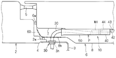
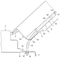
以下、実施形態に係るワイヤーハーネス配策構造部10について説明する(図1、図4参照)。このワイヤーハーネス配策構造部10は、自動車の車体2からドア6にワイヤーハーネスWHを配策するものである。ここで、車体2とは、金属部材で形成されたフレーム部分に加えて樹脂で形成されたインストルメントパネル3等の内装部材も含むものとする。
ワイヤーハーネスWHは、ドア6に搭載されるパワーウインドウ、ドアロック等の電気機器に対して電源供給又は信号伝達するための複数の電線が、配策経路に対応して適宜束ねられて構成されている(図2、図5参照)。ここで、ワイヤーハーネスWHのうち車体2からドア6に配策されるのは、複数の電線が1本に束ねられている部分である。そして、ワイヤーハーネスWHは、ドア6内で分岐して各種電気機器に接続される。
ドア6は、車体2の出入口を開閉可能なように、車体2に対してドアヒンジ5で連結されている(図1、図4参照)。説明の便宜上、ドア6は、垂直方向に沿った軸周りに姿勢変更するように車体2に連結されているものとする。
車体2及びドア6には、それぞれ、ドア6の周縁部又は車体2の出入口の開口縁部(フレーム4の開口縁部)に沿って、防水用のウェザーストリップ2w、6wが取り付けられている(図1、図2、図4、図5参照)。各ウェザーストリップ2w、6wは、ドア6を閉めた状態で、車体2のフレーム4の開口縁部又はドア6の周縁部に密着して車室内外において水密状態を保持できるゴム等で形成された部材である。
そして、ワイヤーハーネスWHは、車体2とドア6との間で各ウェザーストリップ2w、6wより車室内側に配策される(図1、図4参照)。ここでは、ワイヤーハーネスWHが、車体2のインストルメントパネル3の側部からフロントサイドドアの車体2前方側端部に架け渡されて、車体2とドア6との間で配策される例で説明する。なお、インストルメントパネル3とは、計器類を覆う部分のみを指すのではなく、ここではその周辺(前列座席の前方)の内装部材(ダッシュボードとも呼ばれる)も含むものとする。
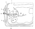
車体2のインストルメントパネル3の側部には、インストルメントパネル3内にワイヤーハーネスWHを挿通するための車体側孔部3hが形成されている。この車体側孔部3hは、上記ウェザーストリップ2w、6wより車室内側に形成されている。また、ドア6は、金属材料で形成されたドアインナーパネル7と樹脂材料等で形成された内装部材としてのトリム8とを有している。ドア6のうち車体2の先端側の部分には、ドアインナーパネル7とトリム8のいずれか一方又は両方に、ワイヤーハーネスWHをドア6内に挿通するためのドア側凹部が形成されている。ここでは、ドアインナーパネル7とトリム8との両方にドア側凹部7h、8hが形成されている。そして、ワイヤーハーネスWHは、車体2側から車体側孔部3hを通じてドア6側に架け渡され、ドア側凹部7h、8hを通じてドアインナーパネル7とトリム8との間に配策され(図3、図6、図10参照)、分岐して各種電気機器に接続される(図2、図5参照)。なお、車体2の車体側孔部3hが形成されている部分とドア6のドア側凹部7h、8hが形成されている部分とは、ドア6を閉めた状態で車体2又はドア6と対向して車室内から見え難くなっている。
ワイヤーハーネス配策構造部10は、外装部材20と、取付部材30と、収容部40と、案内部50と、柔軟防音部材60とを備えている(図1、図4参照)。
ワイヤーハーネスWHのうち車体2からドア6に架け渡される部分には、外装部材20が外装されている。この外装部材20は、ワイヤーハーネスWHを挿通させた状態で外部から保護すると共に、ワイヤーハーネスWHを車体2とドア6との間で垂れ等を抑制して支持する部材である。
外装部材20は、筒状に形成され、ワイヤーハーネスWHを挿通した状態で保護する。より具体的には、外装部材20には、ドア6の開閉動作に対応して車体2とドア6との間で曲がるように可撓性を有する部材が採用される。ここでは、外装部材20は、合成樹脂又は合成ゴム等のエラストマーを、押出成型すると共にバキューム成型或いはブロー成型して製造されたコルゲートチューブである。また、この外装部材20は、扁平な形状(例えば、断面視略楕円形、略長方形等の扁平な形状)に形成されている。なお、ワイヤーハーネスWH自体も扁平な形状に束ねられ、外装部材20がワイヤーハーネスWHの外部形状に対応する扁平な形状に形成されているとよい。
もっとも、外装部材20は、上記コルゲートチューブに限られるものではない。例えば、外装部材は、樹脂を金型で射出成型することにより角筒状又は円筒状等に製造したプロテクタを用いてもよい。この場合、外装部材は、ドア6の開閉動作に対応して動作可能なように一端部がヒンジを介して車体側に取り付けられるとよい。
上記外装部材20は、一端側部分が取付部材30を介して車体2に固定され、他端部が自由端とされる。
取付部材30は、ワイヤーハーネスWHを車体2側に配策するように、ワイヤーハーネスWHに外装されている外装部材20の一端部を車体2に取り付ける部材である。この取付部材30は、外装部材20の一端側部分が固定されると共に、車体2に取り付け可能に構成されている。ここでは、取付部材30は、インストルメントパネル3の側部に形成されているワイヤーハーネスWH挿通用の車体側孔部3hに対して取り付けられる。より具体的には、取付部材30は、車体側孔部3hに対して、一方側(ここではドア側)から押し付けることにより取り付け可能に構成されている。この取付部材30は、車体側孔部3hに対して嵌合可能な嵌合部32と、外装部材20の一端側部分を位置決め可能な位置決め部38とを有している(図7、図8参照)。
嵌合部32は、挿入部34と、押え部36とを有している。挿入部34は、車体側孔部3h内に挿入可能、且つ、内側に外装部材20を挿通可能な筒状に形成されている。この挿入部34は、車体側孔部3hに対してドア側から挿入される(以下、この方向を挿入方向Sという)。挿入部34の先端側部分には、挿入部34を車体側孔部3h内に挿入した状態で車体側孔部3hに係止可能な係止部35が設けられている。この係止部35は、挿入部34の周方向複数位置(ここでは等間隔に4箇所)から外周側に突出するように形成され、それぞれ、車体側孔部3hの周縁部に対して挿入方向S前方側から接触可能な係止面を有している。より具体的には、係止部35は、挿入部34の先端側から基端側に向けて徐々に突出寸法が大きくなるように形成されている。そして、各係止部35は、挿入部34が車体側孔部3hに挿入される際に、挿入部34又は係止部35自身が挿入部34の内周側に弾性変形し、車体側孔部3hを乗り越えた位置で外周側に弾性復帰して車体側孔部3hの周縁部に係止するようになっている。
押え部36は、挿入部34の基端部に連続して設けられ、その外周側に突出する鍔状に形成されている。この押え部36は、車体側孔部3hの周縁部に対して、挿入方向S後方側から面接触可能である。すなわち、押え部36の外周形状は、車体側孔部3hより大きく形成されている。
そして、挿入部34が車体側孔部3hに挿入されると、係止部35が車体側孔部3hの周縁部に対して挿入方向S前方側から係止した状態で、押え部36が車体側孔部3hの周縁部に対して挿入方向S後方側から面接触する。これにより、車体側孔部3hの周縁部が、係止部35と押え部36との間に挟まれて、嵌合部32が車体側孔部3hに対して嵌合した状態となる。
位置決め部38は、嵌合部32の基端部(押え部36の基端部)の内周部から、挿入方向S後方に向けて板状に突出するように形成されている。そして、ワイヤーハーネスWHが嵌合部32内に挿通された状態で、当該ワイヤーハーネスWHを位置決め部38に対してテープT巻き又はタイバンドで締め付け固定することにより、ワイヤーハーネスWHは、取付部材30に対して固定される。なお、タイバンドとは、係止部が複数の被係止部に対して選択的に係止することにより環状体の周方向寸法を変更し保持可能な部材をいう。図8では、テープT巻きした形態を示している。また、位置決め部38の先端部には、テープT又はタイバンドの抜止め用の突起が形成されているとよい。すなわち、位置決め部38の先端部から、嵌合部32の外周側に向けて突起する部分を設ければよい。
なお、位置決め部38は、嵌合部32の挿入方向S後方に向けて突出する形状に限られず、嵌合部32に挿通される外装部材20の経路に対応して、当該経路に沿って挿入方向Sに対して傾斜する方向に突出していてもよい。
上記取付部材30は、樹脂材料を射出成型することにより一体形成されるとよい。
もっとも、取付部材30は、上記形態に限られるものではない。例えば、取付部材30は、外装部材20としてのコルゲートチューブの外周部に対して嵌合可能で、この嵌合状態で車体側孔部3hに取付可能に構成されていてもよい。より具体的には、上記取付部材30の嵌合部32が半割り状にされた形状の一対のブロックが、ヒンジにより一端部同士で開閉可能に連結され、閉状態でコルゲートチューブの外周部に対して嵌合可能なように、各内周部にコルゲートチューブの外周形状に対応した凹凸面が挿入方向Sに連続して形成された構成を採用することができる。すなわち、コルゲートチューブを一対のブロックの内側に挟むことにより嵌合して位置決め可能で、この状態で車体側孔部3hに対して嵌合されて取り付けられる。この取付部材の構成によれば、ワイヤーハーネス配策構造部10の車両組付け前に、ワイヤーハーネスWH及び外装部材20を挿通させておかなくても、後の組付工程で取付位置を調節しながら取り付けることができる。このように、車両組付け工程における取付位置の調節の観点から言うと、取付部材としてヒンジを用いた嵌合構造を採用することが好ましい。
また、取付部材30は、車体2に取付可能で且つ外装部材20を固定可能であればよく、上記のような樹脂成形品に限られず、合成ゴム等のエラストマーで成形されたグロメットであってもよい。
収容部40は、外装部材20の他端部から延出されるワイヤーハーネスWHを迂回させて(ここでは巻いて)余長吸収可能に収容可能に構成されている(図2、図5参照)。また、案内部50は、外装部材20のうち自由端とされた他端側部分を収容部40に向けて挿通案内可能に延在する溝状又は筒状に形成されている。ここでは、収容部40と案内部50とは、一部品のプロテクタPとして成形されている。
より具体的には、案内部50は、一端部にワイヤーハーネスWHの他端側部分を挿入可能な出入口を有し、他端部が収容部40の一端部と連続している。また、収容部40は、一端部が案内部50に連続し、案内部50内に挿入される外装部材20の他端部から延出されるワイヤーハーネスWHを巻いて収容可能な収容空間を有する筐状に形成されている。すなわち、収容部40の収容空間は、収容部40に向けて延在する案内部50の内部空間の他端側に連通している。さらに、収容部40には、巻いたワイヤーハーネスWHをドア6内に引出可能な引出口42が形成されている。つまり、プロテクタPは、案内部50内に挿入される外装部材20を収容部40に向けて案内し、その外装部材20の他端部から延出されるワイヤーハーネスWHを収容部40内で巻いて収容し、引出口42を通じてその外方に延出させる。
そして、プロテクタPは、ドア6の閉状態において、案内部50がドア側凹部7hを通じて車体2の前後方向に沿って延在し、案内部50が収容部40に対して車体2の前方側に位置するように、ドアインナーパネル7とトリム8との間に配設されている。より具体的には、案内部50の一端部の位置は、ドア6を閉めた状態で、車体2の前後方向において車体側孔部3hより後方である。
また、プロテクタPは、上記位置で、ドアインナーパネル7に対して固定可能に構成されている。この構成としては、ドアインナーパネル7に形成される孔部に対して嵌合可能なクランプ構造を有する構成、又は、ネジ止めにより固定可能なブラケット構造を有する構成等を採用することができる。そして、プロテクタPは、その両側方にドアインナーパネル7に対して固定可能な構成を設けることにより、自動車の左右両方のドア6に適用でき、汎用性に優れてコスト削減にも寄与する。
以下、案内部50及び収容部40それぞれの構成について、より詳細に説明する。
案内部50は、外装部材20より大きい内部空間を有する筒状(ここでは、断面視長方形の角筒状)に形成されている。もっとも、案内部50は、外装部材20を挿通案内可能であればよく、溝状でも、断面視略楕円形、円形、長方形以外の多角形等の筒状等に形成されていてもよい。
この案内部50は、一端側部分が一端縁部に向かうにつれて広がるように形成されている。すなわち、外装部材20は、ドア6の開閉時に、車体2とドア6との間で車体2の略上下方向の軸周りに曲げられながらドア6に連動する。そして、案内部50の一端部が幅方向(ここでは、ドア6の内外方向)に広がった形状(図1、図4参照)を採用することにより、略上下方向の軸周りに曲げられる外装部材20を、スムーズに案内部50内に誘い込むことができる。
また、取付部材30と案内部50の一端部とは、車体2の略上下方向にずれた位置に設けられている。すなわち、外装部材20は、取付部材30に固定される一端側部分と、案内部50に挿入される他端側部分との高さが異なり、その間の位置で、車体2の略上下方向に段差を有して延在している(図2、図5参照)。例えば、外装部材20は、30mm以上の段差を有して架け渡されているとよい。この構成は、車体2とドア6との間に架け渡されるワイヤーハーネスWHに加わる力を分散するためのものである。
すなわち、外装部材20が水平面上に延在し、ドア6の開閉動作に応じて水平面上で曲げられる場合、外装部材20のうち一部分で屈曲癖がついて屈曲されることが想定される。この場合、外装部材の内部のワイヤーハーネスWHも一部分で屈曲され、その部分に集中して力が加わる恐れがある。これに対して、外装部材20が高さ方向に段差を有して延在する構成の場合、図9に示すように、ドア6の開閉時に外装部材20が車体2の略上下方向の軸周りに曲げられると、車体2の略上下方向にも延在する部分において、内部のワイヤーハーネスWHが中心軸周りにねじれる。このため、ドア6の開閉時に外装部材20の内部のワイヤーハーネスWHに加わる力は、車体2の略上下方向の軸周りの曲げ方向と中心軸周りのねじり方向とに分散される。また、ねじり方向に加わる力は、曲げ方向に加わる力に比べ、ワイヤーハーネスWHの延在方向において広範囲に作用する。このため、ワイヤーハーネスWHにおいて、力が作用する箇所も分散される。これにより、ワイヤーハーネスWHの曲げ方向の変形量は小さくなり、一部分に掛かる負荷を小さくすることができる。なお、図9では、ドア6が閉状態における外装部材20を実線で示すと共にドア6の開状態における外装部材20を2点鎖線で示し、ドア6が閉状態から開かれる際のワイヤーハーネスWHのねじれ方向を矢印Wで示している。
ここでは、取付部材30が、案内部50の一端部より高い位置に設けられている。換言すると、車体側孔部3hが、ドア側凹部7h、8hより高い位置に設けられているのである。もっとも、取付部材30と案内部50の一端部とが同じ高さ位置に設けられていてもよいが、上記ワイヤーハーネスWHに加わる力を分散する観点から言うと、取付部材30と案内部50の一端部との高さ位置をずらすとよい。
上記のように、取付部材30と案内部50の一端部とが車体2の略上下方向にずらして設けられている構成に対応して、案内部50の一端側部分は、車体2の略上下方向のうち少なくとも取付部材30側に広がるように形成されている。すなわち、外装部材20が、車体2の略上下方向において、案内部50側(ここでは下側)から取付部材30側(ここでは上側)に向けて傾斜して延在するため、取付部材30側(上側)で広がっていることが好ましい。
ここでは、案内部50は、一端側部分の周方向全体が一端縁部に向かうにつれて広がるラッパ状に形成されている(図1、図2、図4、図5参照)。これにより、プロテクタPは、左右いずれのドアにも適用可能であると共に、取付部材30より案内部50の一端部が高い位置に設けられる場合にも適用可能で、汎用性に優れるためコスト削減にも寄与する。また、案内部50の一端側部分は、滑らかな曲線を描くように広がっている。
ここで、案内部50と外装部材20との関係について説明しておく。外装部材20は、一端側部分が車体2に取り付けられた取付部材30に固定された状態で、ドア6が開状態のとき、少なくとも他端側の一部が案内部50内に挿入されている程度に長い延在寸法に設定されているとよい。一方、案内部50は、ドア6が閉状態のとき、内側に進入する外装部材20の他端側部分を他端部まで収容可能な程度に長い延在寸法に設定されているとよい。このように、外装部材20の他端部は、ドア6の開閉時に案内部50内でその延在方向に案内されて移動する。この外装部材20の他端部の案内部50に対する進退移動量はドア6の開閉態様等によって異なるが、例えば100mm移動される場合、案内部50の延在寸法は、100mmより大きく設定される。もっとも、案内部50は、上記寸法より短く、ドア6の閉状態で外装部材20の他端部が案内部50の他端部を越えて収容部40内に突出するものでもよいが、外装部材20の他端部から延出するワイヤーハーネスWHが収容部40内で巻かれるのを妨げない程度に設定されていることが好ましい。
収容部40は、ドア6の閉状態において収容空間内に進入するワイヤーハーネスWHを巻いて収容可能に形成されている。ここでは、ワイヤーハーネスWHを1周巻いて収容可能になっている。好ましくは、収容部40は、ワイヤーハーネスWHを収容空間内で屈曲させずに巻ける程度に大きいとよい。また、収容部40の内側の幅寸法(ドア6の内外方向寸法)は、巻いたワイヤーハーネスWHを交差可能、すなわち、ワイヤーハーネスWHの直径の2倍より大きい(ここでは僅かに大きい)寸法に設定されている。なお、図1及び図4では、収容部40と案内部50とが略同じ幅寸法(ドア6の内外方向寸法)に表されているが、案内部50は、外装部材20の外形状に対応した断面形状に形成され、収容部40より小さい幅寸法に設定されていてもよい。
また、収容部40内には、巻き軸部44が設けられている。この巻き軸部44は、収容部40の幅方向に亘る柱状(ここでは円柱状)に形成されている。収容部40内に収容されるワイヤーハーネスWHは、巻き軸部44周りに巻かれる。より具体的には、巻き軸部44は、外周側に、収容部40の内周部に対してワイヤーハーネスWHを配設可能な間隔をあけて設けられていればよい。
また、収容部40の引出口42は、収容部40のうち案内部50との連通部分に対向する位置に開口している。この引出口42には、その開口縁部が部分的に延出した形状のドア内位置決め部43が形成されている。
そして、引出口42から引き出されるワイヤーハーネスWHをドア内位置決め部43に対してテープT巻き又はタイバンドで締付け固定することにより、ワイヤーハーネスWHが、収容部40の外方のドア6内においてドア6に対して位置決めされる。このため、ドア6の開閉時に収容部40内に車体2側のワイヤーハーネスWHが進退しても、ドア6内に配策されるワイヤーハーネスWHに対して引っ張り又は弛みが発生することを抑制できる。なお、図2、図5では、テープT巻きした形態を示している。
他にも、ワイヤーハーネスWHを収容部40に対して固定する構成としては、径方向内側に向けて突出する複数の爪部が前記径方向に弾性変形可能に設けられた環状部材に対して、外嵌部材を外嵌めすることにより複数の爪部を径方向内側に向けて弾性変形させることが可能な構成を採用することができる。なお、前記環状部材は、引出口42に固定されているとよい。すなわち、環状部材にワイヤーハーネスWHを挿通した状態で、当該環状部材に外嵌部材を外嵌めすることにより、ワイヤーハーネスWHを収容部40に対して固定することができる。
上記収容部40及び案内部50を有するプロテクタPは、例えば、凹状部材と蓋状部材とが合体されて成る構成を採用することができる。なお、図2、図3、図5、図6では、蓋状部材を省略したプロテクタPを示している。そして、プロテクタPは、凹状部材と蓋状部材とを、それぞれ樹脂材料を金型に流し込んで射出成型し、合体させることにより得ることができる。もっとも、プロテクタPは、全体として凹状に形成され、トリム8により開口を塞がれるように構成されていてもよい。
もっとも、収容部40と案内部50とは、一部品のプロテクタPとして形成される場合に限られず、案内部50の他端側に案内部50とは別体の収容部40が設けられ、案内部50により収容部40に向けて外装部材20が案内されていればよい。
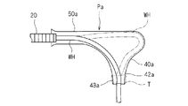
また、プロテクタPは、上記構成に限られるものではなく、図11に示すプロテクタPaのような構成を採用することもできる。プロテクタPaは、案内部50と収容部40aとを有し、ワイヤーハーネスWHを、案内部50の出入口から挿入し、収容部40a内で余長吸収させて、前記出入口と略直交する向きに開口する引出口42aを通じてドア6内に引き出し可能な構成である。この収容部40aは、案内部50から引出口42aに向けてなだらかな曲面に形成された一方の壁面と、案内部50から離間する向きに膨らんでから引出口42aに向かう他方の壁面とを有している。そして、収容部40は、収容したワイヤーハーネスWHを、一方の壁面に沿った経路(図11の実線)と、他方の壁面に沿った経路(図11の二点鎖線)との間で収容可能である。すなわち、収容部40aに収容されるワイヤーハーネスWHは、余長が比較的少ない場合に一方の壁面に沿った経路に近づいた形状で収容され、余長が多くなるにつれて他方の壁面に沿った経路に近づいた形状で収容される。また、この構成においても、ワイヤーハーネスWHを、ドア側位置決め部43aに対してテープT止め、タイバンドにより締付けして、収容部50に対して固定することができる。また、上述した複数の爪部を有する環状部材と外嵌部材との組み合わせによってもワイヤーハーネスWHを収容部50に対して固定することができる。
柔軟防音部材60は、ドアインナーパネル7とトリム8との間に挿入される外装部材20がドアインナーパネル7又はトリム8に擦れて異音が発生するのを抑制するための部材である。すなわち、外装部材20は、ドア6の開閉時にドア側凹部7h、8hを通じてドア6内(案内部50内)に挿入されるため、ドア6の開閉動作に連動してドア6内に進退するとドア側凹部7h、8hに当接する恐れがある。そして、このドア側凹部7h、8hは、金属材料で形成されるドアインナーパネル7又は樹脂材料で形成されるトリム8の一部であるため、比較的硬く、外装部材20と接触して擦れると異音が発生してしまう。
柔軟防音部材60は、案内部50の一端側に設けられ、外装部材20の外周部に接触するように外装部材20を挿通させている。すなわち、外装部材20の他端側部分は、柔軟防音部材60を通じてドア6内に挿入される。
この柔軟防音部材60は、ドアインナーパネル7及びトリム8より柔軟な材料(ここでは、合成ゴム等のエラストマー)により形成されている。すなわち、柔軟防音部材60は、外装部材20が接触して擦れるときの音が、ドアインナーパネル7及びトリム8に接触して擦れたときの音より小さくなるような材料で形成されている。このため、防音性能の観点から言うと、柔軟防音部材60は、より柔軟な材料で形成されているとよい。
ここでは、柔軟防音部材60は、外装部材20を挿通可能なスリットを有し、トリム8のドア側凹部8hを塞ぐように設けられている。そして、柔軟防音部材60は、スリットがドア6の閉状態で車体2の前後方向に延びる姿勢で設けられている。より具体的には、柔軟防音部材60は、スリットを挟んで対向する一対の対向片が弾性変形容易で、挿通された外装部材20が一対の対向片を容易に押し退けて進退可能であるとよい。この一対の対向片は、例えば、薄肉に形成され、さらに対峙する先端側ほど厚さ寸法が小さくなるように形成されているとよい。また、柔軟防音部材60は、外装部材20が案内部50内に進退するのを妨げない(外装部材20に引っ掛からない)ようにスリットが幅広に設定されていてもよい。一方、外装部材20は、柔軟防音部材60を押し退けて案内部50内に進退可能な程度に硬質である(曲がり難い)とよい。上記のように、柔軟防音部材60はトリム8のドア側凹部8hを塞ぐように設けられるため、ドア側凹部8hが塞がれてドア6内部が見え難くなって、ドア6の開状態における見栄えも向上する。
そして、外装部材20は、柔軟防音部材60のスリットを通じてドア6内の案内部50内に挿入され、ドア6の開閉時にスリット内をその延在方向に移動しつつドア6(案内部50)内に進退される。
もっとも、柔軟防音部材60は、スリットが形成された形状に限られるものではない。例えば、柔軟防音部材は、薄肉のゴムに対して一点を中心に放射状に切込みが入れられることにより、前記一点に位置する先端部が自由端となる複数の略三角形状部分が周方向に並んだ形状を採用することができる。そして、この柔軟防音部材を、ドア側凹部8hを塞ぐようにトリム8に設け、複数の略三角形部分の先端部を押し広げて外装部材20を挿通させるように設ければよい。また、柔軟防音部材は、毛、柔軟な樹脂、ゴム等によりブラシ状に形成され、その先端部間に外装部材20を挿通させるように設けられていてもよい。
また、柔軟防音部材60は、プロテクタPに設けられてもよい。例えば、プロテクタに、案内部50の一端側に延びる柔軟防音部材取り付け用の延出部を設け、この延出部に柔軟防音部材を設けて、柔軟防音部材を通じてワイヤーハーネスWHを案内部50内に挿入するように構成してもよい。この場合、柔軟防音部材は、トリム8のドア側凹部8hに取り付けられる場合の位置と略同じ位置に設けられるとよく、具体的には、ドア側凹部8hをトリム8の内側(ドアインナーパネル7側)から塞ぐように設けられるとよい。
上記ワイヤーハーネス配策構造部10は、車体2からドア6内に配策されるワイヤーハーネスWH、外装部材20、取付部材30及びプロテクタPをモジュール化して、車両組み付け前に組み立てておくことができる。すなわち、ワイヤーハーネスWHを外装部材20内に配設すると共にプロテクタPの案内部50及び収容部40内に配設してドア内位置決め部43に固定し、外装部材20の一端側部分を取付部材30に挿通して固定しておけばよい。なお、柔軟防音部材60についても、車両組み付け前に、外装部材20を挿通させた状態に組み付けておくことが可能である。また、柔軟防音部材がプロテクタに設けられる場合には、ワイヤーハーネス配策構造部全体を、より容易にモジュール化することができる。
上記ワイヤーハーネス配策構造部10は、取付部材30が、インストルメントパネル3の側部に形成されている車体側孔部3hに取り付けられる場合に限られない。例えば、図12に示すように、車体2aのフレーム4aの一部に車体側孔部4hが形成され、この車体側孔部4hに取付部材30が取り付けられてもよい。つまり、この場合、ワイヤーハーネスWHは、車体2のフレーム4aとドア6との間に架け渡される。
また、これまで、ワイヤーハーネス配策構造部10を、車体2とドア6としてのフロントサイドドアとの間に適用する例で説明したが、リアサイドドアにも適用可能である。この場合、センターピラー(フロントサイドドアとリアサイドドアとの間のピラー)とリアサイドドアとの間にワイヤーハーネスWHが架け渡される。すなわち、センターピラーに車体側孔部が形成され、ここに取付部材が取り付けられる。
上記構成に係るワイヤーハーネス配策構造部10によると、ワイヤーハーネスWHに外装されている外装部材20が、案内部50により、ワイヤーハーネスWHの余長吸収をする収容部40に向けて案内されている。さらに、案内部50は、収容部40と反対側の一端側部分が一端縁部に向かうにつれて広がるように形成されている。このため、外装部材20が案内部50に案内されることにより、車体2とドア6との間に配策されるワイヤーハーネスWHを、よりスムーズにドア6の開閉動作に連動させることができる。
また、取付部材30と案内部50の一端部とが、車体2の略上下方向にずれた位置に設けられている。すなわち、取付部材30と案内部50の一端部との間に渡っている外装部材20内のワイヤーハーネスWHは、ドア6の開閉時に、両端側部分が車体2の略上下方向において異なる平面上で移動されるため、その間で車体2の略上下方向にも変位して延びる部分が屈曲変形だけでなくねじれ方向にも変形する。これにより、ワイヤーハーネスWHに加わる力を分散して、局部的に負荷が掛かることを抑制することができる。そして、案内部50の一端側部分は、車体2の略上下方向のうち少なくとも取付部材30側に広がるように形成されているため、略上下方向にも変位して延びる外装部材20内のワイヤーハーネスWHを、よりスムーズにドア6の開閉動作に連動させることができる。
また、柔軟防音部材60が、案内部50の一端側に設けられ、外装部材20の外周部に接触するように外装部材20を挿通させているため、ドア6の開閉時に案内部50内に進退する外装部材20がドアインナーパネル7、トリム8(特に、ドア側凹部7h、8h)に擦れて発生する異音を抑制することができる。
また、取付部材30は、位置決め部38によりワイヤーハーネスWHに外装される外装部材20の一端側部分を位置決めして、車体側孔部3hに対して一方側から押し付けるだけで嵌合部32が嵌合するように構成されているため、ワイヤーハーネスWHを容易に車体2側に配策することができる。
また、外装部材20が、扁平な形状に形成され、車体2の上下方向に沿って扁平な姿勢で設けられるため、ドア6の内外方向において狭いスペースに配策できると共に、ドア6内に配設される案内部50及び収容部40も扁平な形状にすることができ、ドアインナーパネル7とトリム8との間のスペースが狭いドア6の場合でも適用することができる。
また、ワイヤーハーネス配策構造部10は、ワイヤーハーネスWHをウェザーストリップ2w、6wより車室内側に配策しているため、グロメット等の止水用の部材を省略して、部品点数及び組立工数の削減、これに伴うコストダウン及び作業の効率化を図ることができる。なお、グロメットを用いない構成によれば、輸送時、梱包時のグロメットの変形を防止するためのカバーを用意することを省略することができる。さらに、盗難防止にも寄与する。また、ドア6側にグロメットで取付する場合と比較して、ワイヤーハーネスWHを通す際のグロメットの拡げ作業も省略することができる。
また、ワイヤーハーネス配策構造部10は、ワイヤーハーネスWHをドアインナーパネル7とトリム8との間に配策しているため、ワイヤーハーネスWHを貫通孔に挿通して配策する手間を省けると共に露出した作業スペースで組み付け作業ができ、組付性の向上及び作業の効率化が図れる。
以上のようにこのワイヤーハーネス配策構造部10は詳細に説明されたが、上記した説明は、全ての局面において例示であって、この発明がそれに限定されるものではない。例示されていない無数の変形例が、この発明の範囲から外れることなく想定され得るものと解される。
2、2a 車体
2w、6w ウェザーストリップ
3h、4h 車体側孔部
6 ドア
10 ワイヤーハーネス配策構造部
20 外装部材
30 取付部材
32 嵌合部
38 位置決め部
40 収容部
50 案内部
60 柔軟防音部材
WH ワイヤーハーネス
2w、6w ウェザーストリップ
3h、4h 車体側孔部
6 ドア
10 ワイヤーハーネス配策構造部
20 外装部材
30 取付部材
32 嵌合部
38 位置決め部
40 収容部
50 案内部
60 柔軟防音部材
WH ワイヤーハーネス
Claims (5)
- ワイヤーハーネスをウェザーストリップより車室内側で車体からドアに配策するワイヤーハーネス配策構造部であって、
前記ワイヤーハーネスと、
前記ワイヤーハーネスに外装される外装部材と、
前記外装部材の一端側部分が固定されると共に、前記車体に取り付け可能な取付部材と、
前記ドア内に配設可能で、前記外装部材の他端部から延出される前記ワイヤーハーネスを迂回させて余長吸収可能に収容する収容部と、
前記ドア内に配設可能で、前記外装部材を前記収容部に向けて挿通案内可能に延在する溝状又は筒状に形成され、前記収容部と反対側の一端側部分が一端縁部に向かうにつれて広がるように形成されている案内部と、
を備える、ワイヤーハーネス配策構造部。 - 請求項1に記載のワイヤーハーネス配策構造部であって、
前記取付部材と前記案内部の一端部とは、前記車体の上下方向にずれた位置に設けられ、
前記案内部の一端側部分は、前記車体の上下方向のうち少なくとも前記取付部材側に広がるように形成されている、ワイヤーハーネス配策構造部。 - 請求項1に記載のワイヤーハーネス配策構造部であって、
前記案内部の一端側に設けられ、前記外装部材の外周部に接触するように前記外装部材を挿通させる柔軟防音部材をさらに備えている、ワイヤーハーネス配策構造部。 - 請求項1に記載のワイヤーハーネス配策構造部であって、
前記取付部材は、前記車体に形成されている孔部に対して一方側から押し付けることにより嵌合可能な嵌合部と、前記外装部材の一端側部分を位置決め可能な位置決め部とを有する、ワイヤーハーネス配策構造部。 - 請求項1に記載のワイヤーハーネス配策構造部であって、
前記外装部材は、扁平な形状に形成され、前記車体の上下方向に沿って扁平となる姿勢で設けられる、ワイヤーハーネス配策構造部。
Applications Claiming Priority (2)
| Application Number | Priority Date | Filing Date | Title |
|---|---|---|---|
| JP2010-206572 | 2010-09-15 | ||
| JP2010206572A JP5445410B2 (ja) | 2010-09-15 | 2010-09-15 | ワイヤーハーネス配策構造部 |
Publications (1)
| Publication Number | Publication Date |
|---|---|
| WO2012035795A1 true WO2012035795A1 (ja) | 2012-03-22 |
Family
ID=45831279
Family Applications (1)
| Application Number | Title | Priority Date | Filing Date |
|---|---|---|---|
| PCT/JP2011/054345 Ceased WO2012035795A1 (ja) | 2010-09-15 | 2011-02-25 | ワイヤーハーネス配策構造部 |
Country Status (2)
| Country | Link |
|---|---|
| JP (1) | JP5445410B2 (ja) |
| WO (1) | WO2012035795A1 (ja) |
Cited By (4)
| Publication number | Priority date | Publication date | Assignee | Title |
|---|---|---|---|---|
| JP2013233870A (ja) * | 2012-05-09 | 2013-11-21 | Sumitomo Wiring Syst Ltd | ワイヤーハーネス配索構造部 |
| JP2016162521A (ja) * | 2015-02-27 | 2016-09-05 | 古河電気工業株式会社 | グロメットインナ及びグロメット |
| CN112208463A (zh) * | 2019-07-09 | 2021-01-12 | 矢崎总业株式会社 | 线束布线结构、线束模块及线束布线方法 |
| WO2025192399A1 (ja) * | 2024-03-14 | 2025-09-18 | 株式会社オートネットワーク技術研究所 | 車両用ドア及び車両用ドアの交換用内装 |
Citations (4)
| Publication number | Priority date | Publication date | Assignee | Title |
|---|---|---|---|---|
| JPS58113566U (ja) * | 1982-01-29 | 1983-08-03 | 日産車体株式会社 | 車両用扉における配線構造 |
| JP2004106606A (ja) * | 2002-09-13 | 2004-04-08 | Sumitomo Wiring Syst Ltd | ワイヤハーネス用スプールプロテクタ |
| JP2007076623A (ja) * | 2005-09-16 | 2007-03-29 | Sumitomo Wiring Syst Ltd | ワイヤハーネスの配索構造 |
| JP2007076622A (ja) * | 2005-09-16 | 2007-03-29 | Sumitomo Wiring Syst Ltd | ワイヤハーネスの配索構造 |
-
2010
- 2010-09-15 JP JP2010206572A patent/JP5445410B2/ja not_active Expired - Fee Related
-
2011
- 2011-02-25 WO PCT/JP2011/054345 patent/WO2012035795A1/ja not_active Ceased
Patent Citations (4)
| Publication number | Priority date | Publication date | Assignee | Title |
|---|---|---|---|---|
| JPS58113566U (ja) * | 1982-01-29 | 1983-08-03 | 日産車体株式会社 | 車両用扉における配線構造 |
| JP2004106606A (ja) * | 2002-09-13 | 2004-04-08 | Sumitomo Wiring Syst Ltd | ワイヤハーネス用スプールプロテクタ |
| JP2007076623A (ja) * | 2005-09-16 | 2007-03-29 | Sumitomo Wiring Syst Ltd | ワイヤハーネスの配索構造 |
| JP2007076622A (ja) * | 2005-09-16 | 2007-03-29 | Sumitomo Wiring Syst Ltd | ワイヤハーネスの配索構造 |
Cited By (6)
| Publication number | Priority date | Publication date | Assignee | Title |
|---|---|---|---|---|
| JP2013233870A (ja) * | 2012-05-09 | 2013-11-21 | Sumitomo Wiring Syst Ltd | ワイヤーハーネス配索構造部 |
| JP2016162521A (ja) * | 2015-02-27 | 2016-09-05 | 古河電気工業株式会社 | グロメットインナ及びグロメット |
| CN112208463A (zh) * | 2019-07-09 | 2021-01-12 | 矢崎总业株式会社 | 线束布线结构、线束模块及线束布线方法 |
| EP3763574A1 (en) * | 2019-07-09 | 2021-01-13 | Yazaki Corporation | Wire harness routing structure for panel, harness module, and wire harness routing method for panel |
| US11285890B2 (en) | 2019-07-09 | 2022-03-29 | Yazaki Corporation | Wire harness routing structure for panel, harness module, and wire harness routing method for panel |
| WO2025192399A1 (ja) * | 2024-03-14 | 2025-09-18 | 株式会社オートネットワーク技術研究所 | 車両用ドア及び車両用ドアの交換用内装 |
Also Published As
| Publication number | Publication date |
|---|---|
| JP5445410B2 (ja) | 2014-03-19 |
| JP2012061924A (ja) | 2012-03-29 |
Similar Documents
| Publication | Publication Date | Title |
|---|---|---|
| WO2012070268A1 (ja) | ワイヤーハーネス配索構造部およびプロテクタ | |
| CN103648846B (zh) | 线束布线结构部 | |
| JP2012176646A (ja) | ワイヤーハーネス配索構造 | |
| WO2013061627A1 (ja) | ワイヤーハーネス配索構造部 | |
| CN103502054B (zh) | 线束配线构造部 | |
| JP5445410B2 (ja) | ワイヤーハーネス配策構造部 | |
| JP5644596B2 (ja) | ワイヤーハーネス配索構造部 | |
| WO2012147223A1 (ja) | ワイヤーハーネス配索構造部 | |
| JP2013247805A (ja) | ワイヤーハーネス配索構造部 | |
| WO2012153436A1 (ja) | ワイヤーハーネス配索構造部 | |
| JP5549558B2 (ja) | ワイヤーハーネス配策構造部 | |
| JP5630307B2 (ja) | ワイヤーハーネス配索構造部 | |
| JP2013226961A (ja) | ワイヤーハーネス配索構造部 | |
| WO2012124200A1 (ja) | ワイヤーハーネス配索構造部 | |
| JP4412150B2 (ja) | グロメットを用いたワイヤハーネスの配索構造 | |
| JP5853932B2 (ja) | ワイヤーハーネス配索構造部 | |
| JP5799937B2 (ja) | グロメット、およびワイヤーハーネス配索構造部 | |
| JP2012178907A (ja) | ワイヤーハーネス配索構造 | |
| WO2012120719A1 (ja) | ワイヤーハーネス配索構造部 | |
| JP2012111401A (ja) | ワイヤーハーネス配索構造部 | |
| JP2012176649A (ja) | ワイヤーハーネス配索構造 | |
| JP2012182964A (ja) | コルゲートチューブ及びドア用配線装置 | |
| WO2012127723A1 (ja) | ドア用配線装置 | |
| JP6078981B2 (ja) | ワイヤーハーネス配索構造部 | |
| JP2012111407A (ja) | ワイヤーハーネス配索構造部 |
Legal Events
| Date | Code | Title | Description |
|---|---|---|---|
| 121 | Ep: the epo has been informed by wipo that ep was designated in this application |
Ref document number: 11824808 Country of ref document: EP Kind code of ref document: A1 |
|
| NENP | Non-entry into the national phase |
Ref country code: DE |
|
| 122 | Ep: pct application non-entry in european phase |
Ref document number: 11824808 Country of ref document: EP Kind code of ref document: A1 |