WO2012029136A1 - 操作診断装置、操作診断方法、操作診断プログラムおよび記録媒体 - Google Patents
操作診断装置、操作診断方法、操作診断プログラムおよび記録媒体 Download PDFInfo
- Publication number
- WO2012029136A1 WO2012029136A1 PCT/JP2010/064845 JP2010064845W WO2012029136A1 WO 2012029136 A1 WO2012029136 A1 WO 2012029136A1 JP 2010064845 W JP2010064845 W JP 2010064845W WO 2012029136 A1 WO2012029136 A1 WO 2012029136A1
- Authority
- WO
- WIPO (PCT)
- Prior art keywords
- pattern
- moving body
- energy saving
- energy
- deceleration
- Prior art date
- Legal status (The legal status is an assumption and is not a legal conclusion. Google has not performed a legal analysis and makes no representation as to the accuracy of the status listed.)
- Ceased
Links
Images





Classifications
-
- F—MECHANICAL ENGINEERING; LIGHTING; HEATING; WEAPONS; BLASTING
- F02—COMBUSTION ENGINES; HOT-GAS OR COMBUSTION-PRODUCT ENGINE PLANTS
- F02D—CONTROLLING COMBUSTION ENGINES
- F02D29/00—Controlling engines, such controlling being peculiar to the devices driven thereby, the devices being other than parts or accessories essential to engine operation, e.g. controlling of engines by signals external thereto
- F02D29/02—Controlling engines, such controlling being peculiar to the devices driven thereby, the devices being other than parts or accessories essential to engine operation, e.g. controlling of engines by signals external thereto peculiar to engines driving vehicles; peculiar to engines driving variable pitch propellers
-
- G—PHYSICS
- G07—CHECKING-DEVICES
- G07C—TIME OR ATTENDANCE REGISTERS; REGISTERING OR INDICATING THE WORKING OF MACHINES; GENERATING RANDOM NUMBERS; VOTING OR LOTTERY APPARATUS; ARRANGEMENTS, SYSTEMS OR APPARATUS FOR CHECKING NOT PROVIDED FOR ELSEWHERE
- G07C5/00—Registering or indicating the working of vehicles
- G07C5/08—Registering or indicating performance data other than driving, working, idle, or waiting time, with or without registering driving, working, idle or waiting time
- G07C5/0808—Diagnosing performance data
Definitions
- the present invention relates to an operation diagnosis apparatus, an operation diagnosis method, an operation diagnosis program, and a recording medium for diagnosing whether or not an operation for saving energy has been performed.
- the use of the present invention is not limited to the operation diagnosis apparatus, the operation diagnosis method, the operation diagnosis program, and the recording medium.
- Patent Document 1 a driving operation evaluation device that evaluates a user's driving operation, and a driving operation evaluation device that improves fuel consumption during traveling is known (for example, see Patent Document 1 below).
- the user's driving operation is evaluated by comparing the fuel consumption during actual traveling with the fuel consumption measured by a vehicle running test.
- Patent Document 2 Also known is an operation state display device that displays a user's operation state, and that allows a user to recognize an operation that reduces energy consumption (see, for example, Patent Document 2 below).
- Patent Document 2 information for scoring the user's accelerator or brake operation based on the speed at the time of traveling, and for allowing the user to recognize the scoring content and the degree of acceleration / deceleration, the driving operation for reducing the energy consumption. It is displayed as.
- the user's driving operation is evaluated on the basis of the fuel consumption measured by the running test. Since the information measured by the driving test is information measured by, for example, a driving operation of a professional driver under the driving environment set for the driving test, it is different from information obtained by a driving operation of a general user. For this reason, when the information measured by the running test is used as comparison data, the comparison accuracy is lowered, and it is difficult to accurately evaluate the user's driving operation.
- the user's driving operation is scored based only on the acceleration / deceleration during traveling. For this reason, if the user's driving operation is, for example, an EV (Electric Vehicle) vehicle, the driving operation was able to regenerate electric power, and if the user's driving operation is a gasoline vehicle, the consumed fuel is reduced (hereinafter referred to as fuel). As an example, there is a problem that it is difficult for the user to recognize whether or not the driving operation can be performed.
- EV Electric Vehicle
- an operation diagnosis apparatus includes an acquisition unit that acquires a traveling pattern when a moving body is decelerated by a user, and at the time of deceleration of the moving body.
- a specifying unit that specifies a travel pattern that maximizes the amount of energy saved (hereinafter referred to as an energy saving amount), and a travel of the travel pattern acquired by the acquiring unit with reference to the travel pattern specified by the specifying unit Diagnostic means for diagnosing the condition.
- An operation diagnosis method is an operation diagnosis method in an operation diagnosis apparatus for diagnosing a method for operating a moving body by a user, and acquires a traveling pattern when the moving body is decelerated by the user.
- An acquisition step a specifying step that specifies a travel pattern that maximizes the amount of energy saved during deceleration of the mobile body (hereinafter referred to as an energy saving amount), a travel pattern acquired by the acquisition step, and the specifying step.
- an operation diagnosis program according to the invention of claim 12 causes a computer to execute the operation diagnosis method according to claim 11.
- a recording medium according to a thirteenth aspect of the invention is characterized in that the operation diagnostic program according to the twelfth aspect is recorded in a computer-readable state.
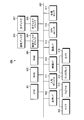
- FIG. 1 is a block diagram illustrating a functional configuration of the operation diagnosis apparatus according to the embodiment.
- FIG. 2 is a flowchart showing a procedure of operation diagnosis processing by the operation diagnosis apparatus.
- FIG. 3 is a block diagram illustrating a hardware configuration of the navigation apparatus.
- FIG. 4 is a flowchart showing the procedure of the operation diagnosis main process by the navigation device.
- FIG. 5 is a flowchart showing another procedure of the operation diagnosis main process by the navigation device.
- FIG. 6 is a flowchart showing the procedure of the travel pattern creation process by the navigation device.
- FIG. 7 is an explanatory diagram showing an optimum pattern of the operation diagnosis main process by the navigation device.
- FIG. 8 is an explanatory diagram showing an example of the optimum pattern by the running pattern creation process by the navigation device.
- FIG. 9 is an explanatory diagram showing another example of the optimum pattern by the running pattern creation process by the navigation device.
- FIG. 1 is a block diagram illustrating a functional configuration of the operation diagnosis apparatus according to the embodiment.
- the operation diagnosis apparatus 100 diagnoses whether or not an operation for saving energy has been performed. Saving energy means regenerating electric power in the case of an EV vehicle, and reducing fuel consumed (hereinafter referred to as fuel cut) in the case of a gasoline vehicle.
- the operation diagnosis apparatus 100 includes an acquisition unit 101, a creation unit 102, a recording unit 103, a specification unit 104, a diagnosis unit 105, an estimation unit 106, a correction unit 107, and a notification unit 108.
- the EV vehicle refers to a moving body that travels using at least electricity as a power source, and includes, for example, an HV (Hybrid Vehicle) vehicle, a PHV (Plug-in Hybrid Vehicle) vehicle, and the like.
- a gasoline vehicle refers to a moving body that travels using fuel as a power source, and includes, for example, a diesel vehicle in addition to a gasoline vehicle.
- the acquisition unit 101 acquires a traveling pattern (hereinafter referred to as a deceleration pattern) when the moving body is decelerated by the user.
- the traveling pattern indicates a transition of information about the moving body that changes as the moving body travels. That is, the deceleration pattern indicates a transition of information regarding the speed at which the moving body starts to decelerate and during deceleration.
- the deceleration pattern indicates the change in speed and acceleration of the moving body only at a predetermined point in time, or the change in speed and acceleration from the start of deceleration to the end of deceleration of the moving body.
- the term “until deceleration of the moving body is completed” refers to until the moving body stops after decelerating or before the moving body is accelerated again after decelerating.
- the speed change and acceleration change of the deceleration pattern may be every predetermined time, every predetermined traveling distance, or whenever the increase or decrease in the energy amount of the moving body becomes the predetermined amount. It may be.
- the acquisition unit 101 acquires information about speed by using, for example, a speed sensor and an acceleration sensor, and information about inclination by using an inclination sensor. Moreover, the acquisition part 101 may acquire the information regarding speed from the information communication network in a moving body.
- the information communication network is an in-vehicle communication network (hereinafter simply referred to as CAN) that is connected to an electronic control unit (ECU: Electronic Control Unit) in a moving body and operates by a communication protocol such as CAN (Controller Area Network).
- the acquisition unit 101 acquires an energy amount (hereinafter referred to as an energy saving amount) that is saved when the moving body is decelerated with the acquired deceleration pattern from the information communication network in the moving body.
- the energy saving amount is the amount of energy regenerated when the moving body is decelerated in the case of an EV vehicle, and is the amount of energy that is fuel cut when the moving body is decelerated in the case of a gasoline vehicle.
- the acquisition unit 101 acquires, from the information communication network in the mobile body, energy consumption actually consumed when the mobile body is decelerated (hereinafter referred to as actual energy consumption).
- the actual energy consumption is an energy amount obtained by subtracting the regenerated energy from the energy consumed when the moving body decelerates in the case of an EV vehicle, and the energy consumed when the moving body decelerates in the case of a gasoline vehicle. .
- the acquisition unit 101 acquires the energy consumption amount estimated by the estimation unit 106 as the actual energy consumption amount, An energy saving amount calculated based on the actual energy consumption amount may be acquired.
- the creation unit 102 creates a travel pattern (hereinafter referred to as an optimal pattern) that maximizes the energy saving amount of the moving body based on the deceleration pattern and the energy saving amount acquired by the acquisition unit 101.
- the optimal pattern is a speed change, acceleration change, and travel distance of the moving body that maximizes the amount of increase in energy saving. It should be noted that the accuracy of calculating the energy saving amount can be further improved by considering the information about the inclination when creating the optimum pattern.
- the creation unit 102 may create a travel pattern in the case where no energy saving amount occurs or in the range where the energy saving amount occurs. Specifically, when the creation unit 102 decelerates from a predetermined deceleration start speed, the creation unit 102 can save energy within the allowable range even when energy cannot be saved at all or even when the energy saving amount does not become the maximum. A driving pattern may also be created when saving can be achieved.
- the creation unit 102 performs a deceleration that does not generate an energy saving amount, a deceleration in a range where the energy saving amount occurs, and a reduction that maximizes the energy saving amount.
- a deceleration change classified as a speed is created as a running pattern.
- the creation unit 102 may create a travel pattern that maximizes the energy saving amount of the moving body based on the energy consumption estimated by the estimation unit 106 and the deceleration pattern acquired by the acquisition unit 101. .
- the creation unit 102 may select an optimum pattern that is most easy for the user to drive.
- the recording unit 103 records the traveling pattern created by the creating unit 102.
- the recording unit 103 records the energy saving amount saved by decelerating the moving body in the traveling pattern created by the creating unit 102 in association with the traveling pattern.
- the recording unit 103 records, for example, a deceleration change for each predetermined deceleration start speed and an energy saving amount corresponding to the deceleration change as one record, and creates a database (DB: DataBase). More specifically, the recording unit 103 creates a DB of the energy saving amount when the vehicle is decelerated at a predetermined deceleration from a predetermined deceleration start speed.
- DB DataBase
- the recording unit 103 may make a DB whether or not the energy saving amount corresponding to the traveling pattern can be generated. Specifically, for example, the recording unit 103 sets “x (impossible)” when the energy saving amount does not occur, and sets “ ⁇ (good, acceptable)” when the energy saving amount occurs within the range where the energy saving amount occurs. When the saving amount is maximized, “ ⁇ (optimum)” is set, and the running pattern is converted to a DB.
- the recording unit 103 may record the energy consumption consumed by the moving body being decelerated in the traveling pattern created by the creating unit 102 in association with the traveling pattern.
- the identifying unit 104 identifies a traveling pattern (optimum pattern) that maximizes the amount of energy saved when the moving body decelerates (energy saving amount). Further, the specifying unit 104 specifies the optimum pattern of the moving body based on the information regarding the speed at the time of starting deceleration and at least one time point during the deceleration traveling of the deceleration pattern acquired by the acquiring unit 101.
- the specifying unit 104 may specify only the deceleration from the plurality of travel patterns recorded by the recording unit 103 based on the deceleration start speed of the moving body, Based on the distance to the planned stop point, the deceleration start speed and the deceleration during the deceleration traveling may be specified from the traveling pattern recorded by the recording unit 103.
- the specifying unit 104 specifies the deceleration from the deceleration start speed Xkm / h when the moving body is decelerating from the speed Xkm / h, for example. Further, for example, when the moving body starts to decelerate from Ym before the planned stop point, the specifying unit 104 specifies the deceleration start speed and the deceleration during deceleration traveling when the moving body stops at a distance of Ym. May be. At this time, the specifying unit 104 may specify a deceleration at one time point during deceleration traveling, or may specify decelerations at a plurality of time points during deceleration traveling.
- the specifying unit 104 may acquire the energy saving amount saved by decelerating the moving body with the specified optimum pattern together with specifying the optimum pattern of the moving body, and energy saving at this time Only the amount may be acquired. Specifically, the specifying unit 104 selects the optimum pattern of the moving body corresponding to the traveling pattern recorded in the recording unit 103 when the moving body travels with the deceleration pattern acquired by the acquiring unit 101. Identify the energy savings corresponding to the pattern.
- the specifying unit 104 starts the deceleration at which the energy saving amount of the moving body is maximized when the moving body is decelerated based on the current position of the moving body, the external situation related to the current position, and the state of the moving body. Specify the point or deceleration start timing.
- the external situation related to the current position is a travel environment of the current position where the mobile body travels, such as a road state where the mobile body travels, weather at that time, and travel conditions of surrounding mobile bodies.
- the state of the moving body includes the number of passengers, the total weight of the moving body including the loaded luggage, the air pressure of the tires, and the presence of attached equipment such as a carrier.
- the external situation relating to the current position and the state of the moving body may be input to an input unit (not shown) by the user, for example, the absolute position of the vehicle from, for example, GPS, or the signal from the DB existing inside and outside the device
- the absolute position such as may be acquired automatically.
- the specifying unit 104 may specify a traveling pattern that can most accumulate energy regenerated by the moving body when the moving body decelerates as the optimum pattern of the moving body. Further, the specifying unit 104 may specify a traveling pattern that can stop the energy supplied to the moving body for the longest time when the moving body is decelerated as the optimum pattern of the moving body.
- the diagnosis unit 105 diagnoses the traveling state of the deceleration pattern acquired by the acquisition unit 101 based on the optimum pattern specified by the specifying unit 104. Specifically, the diagnosis unit 105 determines whether the deceleration pattern of the moving body is a travel pattern that is close to the optimal pattern, a travel pattern that is not a travel pattern that is close to the optimal pattern, but is in a range where an energy saving amount is generated, or energy saving. Diagnose whether the running pattern did not generate a quantity.
- the diagnosis unit 105 may diagnose the traveling state by obtaining an approximation of the energy saving amount acquired by the acquisition unit 101 with the energy saving amount acquired by the specifying unit 104 as a reference.
- the degree of approximation of the energy saving amount is a degree that approximates the reference energy saving amount, and may be a ratio that approximates the reference energy saving amount, or an increase / decrease amount from the reference energy saving amount. There may be.
- the estimation unit 106 is based on a single consumption energy estimation formula composed of first information, second information, and third information having different factors that increase or decrease energy consumption, and unit time during traveling of the mobile object Estimate energy consumption per hit.
- 1st information is the information regarding the energy consumed when the moving body stops in the state where the drive source moved.
- the engine is idled at a low speed to such an extent that no load is applied to the engine of the moving body.
- the stop time of the moving body in a state where the drive source is movable is an idling time.
- the first information is, for example, energy consumption when the vehicle is stopped with the engine running or when it is stopped by a signal or the like. That is, the first information is an energy consumption amount consumed due to a factor not related to the traveling of the moving body. More specifically, the first information is energy consumption by an air conditioner or audio provided in the moving body, and energy consumption consumed by idling in a gasoline vehicle or the like.
- the second information is information related to energy consumed during acceleration / deceleration of the moving body.
- the time of acceleration / deceleration of the moving body is a traveling state in which the speed of the moving body changes with time.
- the time of acceleration / deceleration of the moving body is a traveling state in which the speed of the moving body changes within a predetermined time.
- the third information is information related to energy consumed by the resistance generated when the mobile object is traveling.
- the traveling time of the moving body is a traveling state in which the speed of the moving body is constant within a predetermined time.
- the resistance generated when the mobile body travels is a factor that changes the travel state of the mobile body when the mobile body travels. Specifically, the resistance generated when the mobile body travels is resistance generated in the mobile body due to weather conditions, road conditions, vehicle conditions, and the like.
- the estimation unit 106 estimates the energy consumption amount based on the travel pattern acquired by the acquisition unit 101, and calculates the energy saving amount based on the energy consumption amount. It may be estimated.
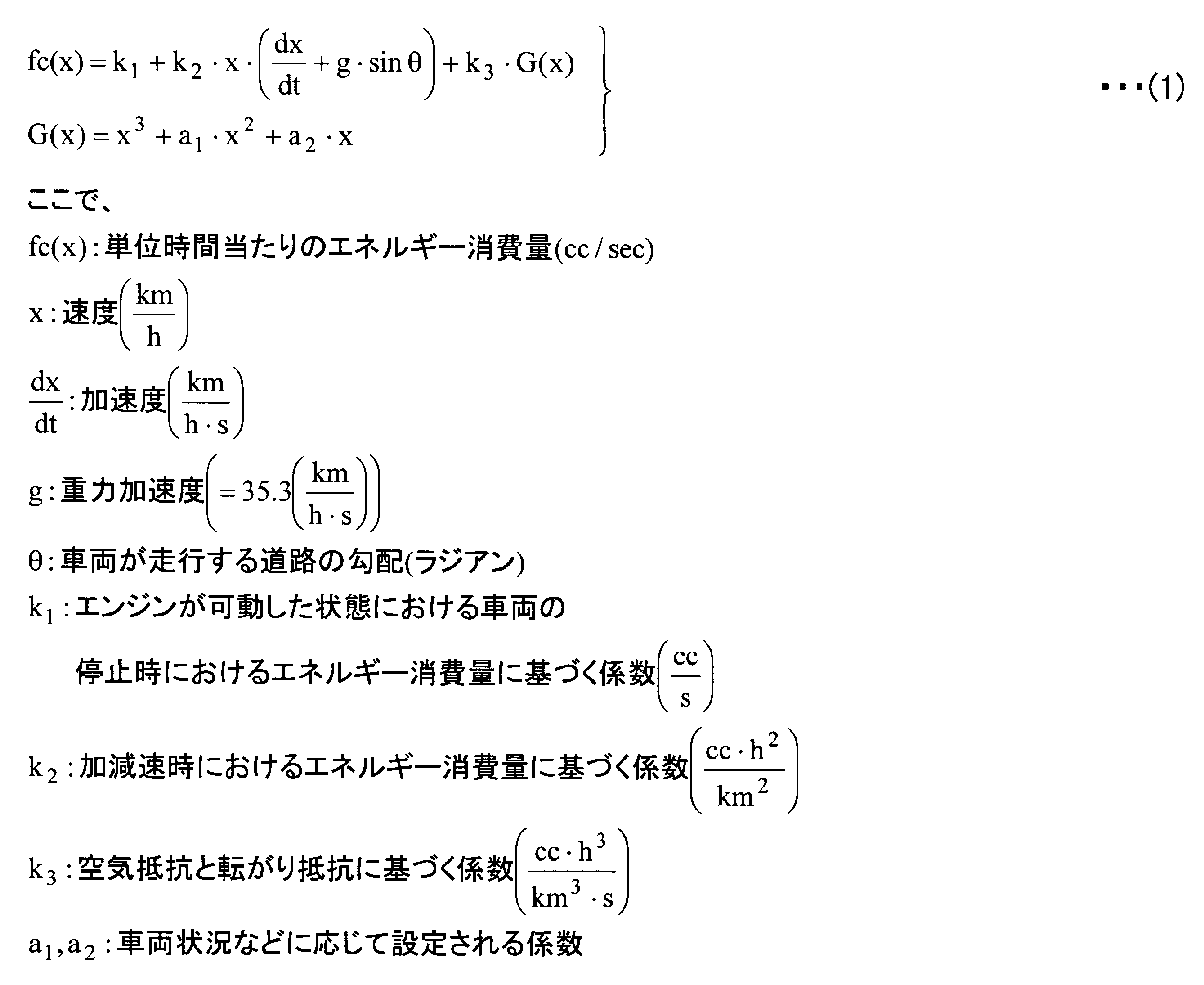
- the estimation unit 106 uses the energy consumption estimation formula shown in the following formula (1) based on the speed and acceleration acquired by the acquisition unit 101 to calculate per unit time during traveling of the moving object. Estimate energy consumption.
- the first term on the right side corresponds to the first information
- the second term on the right side corresponds to the second information
- the third term on the right side corresponds to the third information.
- time (h) and second (s) are mixedly used as a unit representing time, but this employs speed (km / h) as a unit of speed. This is because the second (s) is adopted as the unit time for estimating the fuel consumption. When it is desired to align these units, calculation may be appropriately performed on each numerical value.
- the correction unit 107 corrects information related to the moving body used as a variable of the single energy consumption estimation formula shown in the above-described formula (1).
- the information on the moving body is vehicle information such as the displacement, weight, vehicle width, vehicle height, efficiency, air resistance, rolling resistance, etc. of the moving body.
- the notification unit 108 notifies the user of the diagnosis result diagnosed by the diagnosis unit 105. Further, the notification unit 108 notifies the user of the deceleration start point or the deceleration start timing specified by the specification unit 104. Specifically, the notification unit 108, for example, “We recommend that you decelerate from Ym or more before”, “I showed fuel efficiency performance of X%”, “Updated the highest record of energy savings ”Etc.
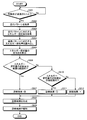
- FIG. 2 is a flowchart showing a procedure of operation diagnosis processing by the operation diagnosis apparatus.
- the operation diagnosis apparatus 100 acquires a traveling pattern (deceleration pattern) of the moving body by the acquisition unit 101 (step S201). At this time, the operation diagnosis apparatus 100 acquires the energy saving amount corresponding to this traveling pattern together with the traveling pattern of the moving body.
- the operation diagnosis apparatus 100 determines whether or not a travel pattern (optimum pattern) that maximizes the energy saving amount has been generated (step S202).
- step S202 When the optimal pattern has been generated (step S202: Yes), the operation diagnosis apparatus 100 specifies the optimal pattern by the specifying unit 104 (step S203). Next, the operation diagnosis apparatus 100 uses the diagnosis unit 105 to diagnose the traveling state of the traveling pattern acquired in step S201 (step S204). Then, the operation diagnosis apparatus 100 notifies the diagnosis result by the notification unit 108 (step S205), and ends the processing according to this flowchart (hereinafter referred to as operation diagnosis main processing).
- step S202 when the optimum pattern has not been generated (step S202: No), the operation diagnosis apparatus 100 creates an optimum pattern by the creation unit 102 (step S206). Then, the operation diagnosis apparatus 100 records the optimum pattern created in step S206 by the recording unit 103 (step S207), and ends the process according to this flowchart (hereinafter referred to as a travel pattern creation process).
- the operation diagnosis apparatus 100 may adjust the diagnosis result notified to the user in step S205 using the technique disclosed in Japanese Patent Application Laid-Open No. 2006-281898. Further, when the operation diagnosis apparatus 100 cannot acquire the energy saving amount in step S201, the operation diagnosis apparatus 100 determines the energy based on the energy consumption estimated using the energy consumption estimation formula shown in the above-described formula (1). A saving amount may be estimated.
- the operation diagnosis apparatus 100 diagnoses the traveling state based on the traveling pattern (deceleration pattern) when the moving body is decelerated by the user. More specifically, the operation diagnosis apparatus 100 creates a travel pattern (optimum pattern) that maximizes the energy saving amount based on the deceleration pattern of the moving object, and saves energy based on the deceleration pattern and the optimal pattern. Diagnose whether or not an operation has been performed. As described above, the operation diagnosis apparatus 100 diagnoses the traveling state based on the information accumulated during actual traveling, and therefore, the energy saving amount as compared with the case where the diagnosis is performed based on the data measured by the traveling test. The user can be notified of an operation for maximizing.
- the operation diagnosis device 100 diagnoses whether or not the driving operation can maximize the energy saving amount, the user's motivation for energy saving can be improved.
- the operation diagnosis apparatus 100 diagnoses whether or not an operation for saving energy has been performed based on an optimum pattern reflecting the actual traveling environment and the state of the moving body, the accuracy of the operation diagnosis can be improved. Can do.
- the operation diagnosis apparatus 100 acquires the data for comparison of the traveling state by the user's operation from the actual traveling data only by the own apparatus, no other apparatus is required. For this reason, the operation diagnosis apparatus 100 has high versatility and can cope with a wide variety of vehicles.
- FIG. 3 is a block diagram illustrating a hardware configuration of the navigation apparatus.
- the navigation apparatus 300 includes a CPU 301, ROM 302, RAM 303, magnetic disk drive 304, magnetic disk 305, optical disk drive 306, optical disk 307, audio I / F (interface) 308, microphone 309, speaker 310, input device 311, A video I / F 312, a display 313, a camera 314, a communication I / F 315, a GPS unit 316, and various sensors 317 are provided.
- Each component 301 to 317 is connected by a bus 320.
- the CPU 301 governs overall control of the navigation device 300.
- the ROM 302 records programs such as a boot program and a data update program.
- the RAM 303 is used as a work area for the CPU 301. That is, the CPU 301 controls the entire navigation device 300 by executing various programs recorded in the ROM 302 while using the RAM 303 as a work area.
- the magnetic disk drive 304 controls the reading / writing of the data with respect to the magnetic disk 305 according to control of CPU301.
- the magnetic disk 305 records data written under the control of the magnetic disk drive 304.
- an HD hard disk
- FD flexible disk
- the optical disk drive 306 controls reading / writing of data with respect to the optical disk 307 according to the control of the CPU 301.
- the optical disk 307 is a detachable recording medium from which data is read according to the control of the optical disk drive 306.
- a writable recording medium can be used as the optical disc 307.
- an MO, a memory card, or the like can be used as a removable recording medium.
- Examples of information recorded on the magnetic disk 305 and the optical disk 307 include map data, a traveling pattern (deceleration pattern) when the vehicle is decelerated, energy saving amount corresponding to the deceleration pattern, energy consumption amount, and energy saving amount.
- the maximum driving pattern (optimum pattern), the energy saving amount corresponding to the optimal pattern, and the like can be mentioned.
- the map data includes background data representing features (features) such as buildings, rivers, and the ground surface, road shape data representing road shapes by links and nodes, and the like.
- the voice I / F 308 is connected to a microphone 309 for voice input and a speaker 310 for voice output.
- the sound received by the microphone 309 is A / D converted in the sound I / F 308.
- the microphone 309 is installed in a dashboard portion of a vehicle, and the number thereof may be one or more. From the speaker 310, a sound obtained by D / A converting a predetermined sound signal in the sound I / F 308 is output.
- the input device 311 includes a remote controller, a keyboard, a touch panel, and the like provided with a plurality of keys for inputting characters, numerical values, various instructions, and the like.
- the input device 311 may be realized by any one form of a remote control, a keyboard, and a touch panel, but can also be realized by a plurality of forms.
- the video I / F 312 is connected to the display 313. Specifically, the video I / F 312 is output from, for example, a graphic controller that controls the entire display 313, a buffer memory such as a VRAM (Video RAM) that temporarily records image information that can be displayed immediately, and a graphic controller. And a control IC for controlling the display 313 based on the image data to be processed.
- a graphic controller that controls the entire display 313, a buffer memory such as a VRAM (Video RAM) that temporarily records image information that can be displayed immediately, and a graphic controller.
- VRAM Video RAM
- the display 313 displays icons, cursors, menus, windows, or various data such as characters and images.
- a TFT liquid crystal display, an organic EL display, or the like can be used as the display 313, for example.
- the camera 314 captures images inside or outside the vehicle.
- the image may be either a still image or a moving image.
- the outside of the vehicle is photographed by the camera 314, and the photographed image is analyzed by the CPU 301, or a recording medium such as the magnetic disk 305 or the optical disk 307 via the video I / F 312. Or output to
- the communication I / F 315 is connected to the network via a wire or wirelessly, and functions as an interface between the navigation device 300 and the CPU 301.
- Communication networks that function as networks include in-vehicle communication networks such as CAN (Controller Area Network) and LIN (Local Interconnect Network), public line networks and mobile phone networks, DSRC (Dedicated Short Range Communication), LAN, and WAN.
- CAN Controller Area Network
- LIN Local Interconnect Network
- public line networks and mobile phone networks public line networks and mobile phone networks
- DSRC Dedicated Short Range Communication
- LAN Local Area Network
- WAN Wide Area Network
- the communication I / F 315 is, for example, a public line connection module, an ETC (non-stop automatic fee payment system) unit, an FM tuner, a VICS (Vehicle Information and Communication System) / beacon receiver, or the like.
- the GPS unit 316 receives radio waves from GPS satellites and outputs information indicating the current position of the vehicle.
- the output information of the GPS unit 316 is used when the CPU 301 calculates the current position of the vehicle together with output values of various sensors 317 described later.
- the information indicating the current position is information for specifying one point on the map data such as latitude / longitude and altitude.
- the various sensors 317 output information for determining the position and behavior of the vehicle, such as a vehicle speed sensor, an acceleration sensor, and an angular velocity sensor.
- the output values of the various sensors 317 are used by the CPU 301 to calculate the current position of the vehicle and the amount of change in speed and direction.
- the CPU 301 executes a predetermined program using programs and data recorded in the RAM 303, the magnetic disk 305, the optical disk 307, etc., and controls each part in the navigation device 300, thereby realizing its function.
- the navigation device 300 estimates the energy consumption amount per unit time while the vehicle on which the device is mounted is traveling. Moreover, the navigation apparatus 300 estimates an energy saving amount based on the estimated energy consumption.
- the navigation apparatus 300 estimates the energy consumption of the vehicle using the following equation (1).
- the first term on the right side is the energy consumption (first information) consumed during idling
- the second term on the right side is the energy consumption (second information) consumed during acceleration / deceleration
- the third term on the right side is the energy consumption (third information) consumed during traveling at a constant speed.
- time (h) and second (s) are mixedly used as a unit representing time, but this employs speed (km / h) as a unit of speed. This is because the second (s) is adopted as the unit time for estimating the fuel consumption. When it is desired to align these units, calculation may be appropriately performed on each numerical value.
- FIG. 4 is a flowchart showing the procedure of the operation diagnosis main process by the navigation device.
- the navigation apparatus 300 first waits until the vehicle is decelerated (step S401: No loop).
- the navigation apparatus 300 acquires a travel pattern (deceleration pattern) from the start of deceleration of the vehicle to the end of deceleration (step S402).
- the navigation device 300 acquires, for example, a deceleration start speed, an acceleration change during deceleration, and the like as the traveling pattern.
- the navigation device 300 reads a travel pattern (optimum pattern) that maximizes the energy saving amount from the travel patterns stored in the storage device (the magnetic disk 305 or the optical disk 307) (step S403).
- the navigation apparatus 300 compares the travel pattern acquired in step S402 with the optimal pattern acquired in step S403 (step S404).
- the navigation device 300 determines whether or not the travel pattern acquired in step S402 is the optimum pattern based on the comparison result in step S404 (step S405).
- the determination as to whether or not the travel pattern is the optimum pattern is made, for example, according to preset conditions, and the determination criteria are not questioned. If the travel pattern is the optimum pattern (step S405: Yes), the navigation apparatus 300 sets the diagnosis result to, for example, “optimum ⁇ ” (step S406).
- the navigation apparatus 300 produces
- the diagnosis result for notifying the user is a message that allows the user to easily recognize the diagnosis result for his / her traveling state, for example, “the highest record of energy saving amount has been updated”.
- the diagnosis result for notifying the user is generated, for example, as character string data or voice data.
- the navigation apparatus 300 notifies the user of the diagnosis result generated in step S407 from the display 313 or the speaker 310 for audio output (step S408), and the process according to this flowchart ends.
- step S405 determines whether or not the vehicle has been decelerated within the range where the energy saving amount is generated (step S409).
- step S409: Yes the navigation device 300 sets the diagnosis result to “Yes” (step S410), for example, proceeds to step S407, and performs the subsequent processing. After the execution, the processing according to this flowchart is terminated.
- step S409 when the vehicle is not decelerated within the range where the energy saving amount is generated (step S409: No), the navigation device 300 sets the diagnosis result to “impossible ⁇ ” (step S411), and proceeds to step S407. After performing the process, the process according to this flowchart is terminated.
- the operation diagnosis main process shown in FIG. 4 can be applied to a vehicle such as a train traveling on a track, for example.
- the navigation apparatus 300 may transmit the optimum pattern together with the energy saving amount, for example, when the energy saving amount is transmitted from the pantograph provided in the vehicle to another vehicle via the overhead line.
- the navigation apparatus 300 can acquire the distance from the current position of the vehicle to the planned stop point, the remaining travel distance to the planned stop point and the planned stop point where the energy saving amount can be maximized. Based on the distance (hereinafter referred to as the deceleration distance), the user may be notified of the deceleration start point.
- the navigation device 300 may diagnose the running state based on the energy saving amount corresponding to the running pattern of the vehicle with the optimum pattern as a reference.
- Navigation device 300 may diagnose the running state of the vehicle based on the degree of approximation of the energy saving amount.
- FIG. 5 is a flowchart showing another procedure of the operation diagnosis main process by the navigation device.
- the navigation device 300 first waits until the vehicle is decelerated (step S501: No loop).
- step S501: Yes the navigation apparatus 300 acquires a travel pattern (deceleration pattern) from the start of deceleration of the vehicle to the end of deceleration (step S502).
- the navigation apparatus 300 acquires an energy saving amount corresponding to the travel pattern acquired in step S502 via an in-vehicle communication network such as CAN (step S503).
- the navigation apparatus 300 reads the energy saving amount corresponding to the optimum pattern among the energy saving amounts stored in the storage device (step S504).
- the navigation apparatus 300 calculates the degree of approximation of the energy saving amount acquired in step S503 based on the energy saving amount read in step S504 (step S505). That is, the navigation apparatus 300 calculates the degree of approximation of the energy saving amount for the deceleration pattern with reference to the energy saving amount for the optimal pattern.
- the navigation apparatus 300 determines whether or not the degree of approximation calculated in step S505 is within an optimal range (step S506).
- the optimum range is, for example, a range equal to or less than a threshold value that maximizes the energy saving amount.
- the navigation apparatus 300 sets the diagnosis result to, for example, “optimal ⁇ ” (step S507).
- the navigation device 300 performs the processing from step S507 to step S509, and notifies the user of the diagnosis result in the same manner as the operation diagnosis main processing shown in FIG. 4 (step S406 to step S408 in FIG. 4). The process by is terminated.
- the navigation device 300 determines whether or not the degree of approximation calculated in step S505 is within an allowable range (step S510).
- the allowable range is, for example, a range that is less than or equal to a threshold at which the energy saving amount is generated, in a range that exceeds a threshold that maximizes the energy saving amount.
- step S510: Yes When the degree of approximation is within an allowable range (step S510: Yes), the navigation apparatus 300 sets the diagnosis result to, for example, “OK” (step S511), proceeds to step S508, and performs the subsequent processing.
- the process according to this flowchart ends.
- step S510 determines whether the degree of approximation is within the allowable range. If the degree of approximation is not within the allowable range (step S510: No), the navigation apparatus 300 sets the diagnosis result to, for example, “impossible ⁇ ” (step S512), proceeds to step S508, and performs the subsequent processing.
- the process according to this flowchart ends.
- FIG. 6 is a flowchart showing the procedure of the travel pattern creation process by the navigation device.
- the navigation apparatus 300 first waits until the vehicle is decelerated (step S601: No loop).
- the navigation apparatus 300 acquires a travel pattern (deceleration pattern) from the start of deceleration to the end of deceleration (step S602).
- the navigation device 300 determines whether or not the vehicle characteristic information has been acquired (step S603).
- the vehicle characteristic information is information for creating conditions for generating regenerative power and conditions for performing fuel cut, and includes vehicle speed, acceleration, inclination, energy savings, energy consumption, and the like.
- step S603 the navigation apparatus 300 determines whether or not the vehicle characteristic information can be acquired via the in-vehicle communication network such as CAN (step S604).
- vehicle characteristic information can be acquired via the in-vehicle communication network (step S604: Yes)
- the vehicle characteristic information is acquired via the in-vehicle communication network (step S605).
- the navigation device 300 calculates a deceleration distance (optimum deceleration distance) that maximizes the energy saving amount based on the vehicle characteristic information (step S606).
- the optimum deceleration distance is a travel distance for the vehicle to reach the planned stop point in a deceleration state in which the energy saving amount is maximized.
- the navigation apparatus 300 creates an optimum pattern based on the optimum deceleration distance (step S607).
- the navigation device 300 writes the optimum pattern to the storage device (step S608), and ends the processing according to this flowchart.
- step S604 when the vehicle characteristic information cannot be acquired via the in-vehicle communication network (step S604: No), the navigation device 300 estimates the vehicle characteristic information based on the consumption energy estimation formula shown in the above-described formula (1) ( The process proceeds to step S609) and step S606, and after the subsequent processing is performed, the processing according to this flowchart is terminated.
- step S603 Yes
- the process proceeds to step S606, and after the subsequent processing is performed, the processing according to this flowchart is terminated.
- the travel pattern creation process may be performed in consideration of other factors (vehicle information, road information, weather, and traveling conditions of surrounding vehicles).
- FIG. 7 is an explanatory diagram showing an optimum pattern of the operation diagnosis main process by the navigation device.
- the explanatory diagram shown in FIG. 7 shows a traveling pattern (inclination with respect to the time axis) from when the vehicle traveling at a speed of 40 km / h (solid line parallel to the time axis) decelerates from the start of deceleration 700 to stop.
- the diagnosis result is notified.
- an EV vehicle will be described as an example, but the same relationship holds in the case of a gasoline vehicle.
- the traveling pattern connecting the deceleration start time 700 and the scheduled stop time 701 is defined as an optimum pattern 711.
- the optimum pattern 711 is a traveling pattern that decelerates and stops at a deceleration of 7 km / h / sec from 40 km / h. At this time, if the deceleration distance of the optimum pattern 711 is about 31 m, for example, the optimum deceleration distance is about 31 m.
- the travel pattern 712 farthest from the optimum pattern 711 is the travel pattern in which the power is not regenerated most.
- the navigation device 300 notifies the user of a message such as “It is effective to start deceleration 10 m ahead”.
- the travel pattern 713 farthest from the optimum pattern 711 is the travel pattern with the least power regeneration amount.
- the navigation device 300 notifies the user of a message such as “It is effective to start deceleration 10 m before”.
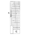
- FIG. 8 is an explanatory diagram showing an example of the optimum pattern by the running pattern creation process by the navigation device.
- the explanatory diagram shown in FIG. 8 is travel pattern data 800 that records the amount of power when the vehicle is decelerated at a predetermined deceleration from a predetermined deceleration start speed.
- the travel pattern data 800 is created by, for example, the navigation device 300 mounted on an EV car.
- the amount of electric power corresponding to the deceleration change of 1 to 7 km / h / sec is recorded in one record at every deceleration start speed of 10 to 50 km / h.
- “x” is recorded when the amount of electric power is not generated, and 1 to 3 W (watts) is recorded when the electric power is regenerated.
- the travel pattern data 800 the travel pattern (the portion indicated by the hatching in FIG. 8) having the power amount of 3 W is the optimum pattern.
- the navigation apparatus 300 has a deceleration of 7 km / h / sec. It is desirable to use a traveling pattern that decelerates as the optimum pattern.
- FIG. 9 is an explanatory diagram showing another example of the optimum pattern by the running pattern creation process by the navigation device.
- the explanatory diagram shown in FIG. 9 is travel pattern data 900 that records the presence or absence of a fuel cut when decelerating at a predetermined deceleration from a predetermined deceleration start speed.
- the travel pattern data 900 is created by, for example, the navigation device 300 mounted on a gasoline vehicle.
- the running pattern data 900 the presence or absence of a fuel cut corresponding to a deceleration change of 1 to 7 km / h / sec is recorded in one record at every deceleration start speed of 10 to 50 km / h. .
- “x” is recorded when the fuel is not cut
- “ ⁇ ” and “ ⁇ ” are recorded when the fuel is cut.
- a running pattern that can last for a long time when the fuel is cut during deceleration is the optimum pattern. That is, in the traveling pattern data 900, the traveling pattern (the portion indicated by ⁇ in FIG. 9) that decelerates at the slowest deceleration among the ⁇ and ⁇ when the fuel is cut is the optimum pattern.
- a fuel cut occurs if the deceleration is 5 km / h / sec or more.
- the navigation device 300 travels at a deceleration of 5 km / h / sec, which can travel for a long time at the slowest deceleration among the decelerations of 5 km / h / sec or more at which a fuel cut occurs. It is desirable to use the pattern as the optimum pattern.
- a travel pattern (optimum pattern) that maximizes the energy saving amount is created based on the deceleration pattern of the moving body, and the energy is calculated based on the deceleration pattern and the optimum pattern. It is diagnosed whether or not an operation for saving is performed.
- the navigation apparatus 300 diagnoses the traveling state based on the information accumulated during actual traveling, the energy saving amount can be reduced as compared with the case where the diagnosis is made based on the data measured by the traveling test. The user can be notified of the operation to maximize.
- the navigation apparatus 300 diagnoses whether or not the driving operation has been able to maximize the energy saving amount, the user's motivation for energy saving can be improved.
- the navigation device 300 diagnoses whether or not an operation for saving energy has been performed based on the optimum pattern reflecting the actual traveling environment and the state of the moving body, the accuracy of the operation diagnosis can be improved. it can.
- the navigation device 300 acquires the data for comparison of the driving state by the user's operation from the actual driving data only by the own device, no other device is required. For this reason, the navigation apparatus 300 has high versatility and can cope with a wide variety of vehicles.
- the operation diagnosis method described in the present embodiment can also be realized by executing a program prepared in advance on a computer such as a personal computer or a workstation.
- This program is recorded on a computer-readable recording medium such as a hard disk, a flexible disk, a CD-ROM, an MO, and a DVD, and is executed by being read from the recording medium by the computer.
- the program may be a transmission medium that can be distributed via a network such as the Internet.
Landscapes
- Engineering & Computer Science (AREA)
- Physics & Mathematics (AREA)
- General Physics & Mathematics (AREA)
- Chemical & Material Sciences (AREA)
- Combustion & Propulsion (AREA)
- Mechanical Engineering (AREA)
- General Engineering & Computer Science (AREA)
- Time Recorders, Dirve Recorders, Access Control (AREA)
- Navigation (AREA)
Abstract
操作診断装置(100)は、エネルギーを節約する操作がなされたか否かを診断する。取得部(101)は、ユーザによって移動体が減速された際の走行パターンを取得する。作成部(102)は、取得部(101)によって取得された減速パターンおよびエネルギー節約量に基づいて、移動体のエネルギー節約量が最大となる走行パターンを作成する。記録部(103)は、作成部102によって作成された走行パターンを記録する。特定部(104)は、移動体の減速時に節約されるエネルギー量(エネルギー節約量)が最大となる走行パターンを特定する。診断部(105)は、特定部(104)によって特定された最適パターンを基準として、取得部(101)によって取得された減速パターンの走行状態を診断する。報知部(108)は、診断部(105)によって診断された診断結果を、ユーザに報知する。
Description
この発明は、エネルギーを節約する操作がなされたか否かを診断する操作診断装置、操作診断方法、操作診断プログラムおよび記録媒体に関する。ただし、この発明の利用は、操作診断装置、操作診断方法、操作診断プログラムおよび記録媒体に限らない。
従来、ユーザの運転操作を評価する運転操作評価装置であって、走行時における燃費を向上させるための運転操作評価装置が知られている(例えば、下記特許文献1参照。)。下記特許文献1では、実際の走行時における燃費と、車両の走行試験により測定された燃費とを比較して、ユーザの運転操作を評価している。
また、ユーザの運転状態を表示する運転状態表示装置であって、エネルギー消費量を低減させる運転操作をユーザに認識させる運転状態表示装置が知られている(例えば、下記特許文献2参照。)。下記特許文献2では、走行時の速度に基づいて、ユーザのアクセルまたはブレーキ操作を採点し、その採点内容や加減速の度合いを、エネルギー消費量を低減させる運転操作をユーザに認識させるための情報として表示している。
しかしながら、上述した引用文献1の技術では、走行試験により測定された燃費を基準として、ユーザの運転操作を評価している。走行試験により測定される情報は、走行試験用に設定された走行環境下で、例えばプロドライバーの運転操作によって計測される情報であるため、一般的なユーザの運転操作によって得られる情報と異なる。このため、走行試験により測定された情報を比較データとして用いる場合、比較精度が低くなり、正確にユーザの運転操作を評価するのが困難であるという問題点が一例として挙げられる。
また、上述した引用文献2の技術では、走行時の加減速度のみに基づいてユーザの運転操作を採点している。このため、ユーザの運転操作が、例えばEV(Electric Vehicle)車の場合、電力を回生することができた運転操作であったか、また、ガソリン車等の場合、消費される燃料を低減(以下、燃料カットという)することができた運転操作であったか否かを、ユーザに認識させることが困難であるという問題点が一例として挙げられる。
上述した課題を解決し、目的を達成するため、請求項1の発明にかかる操作診断装置は、ユーザによって移動体が減速された際の走行パターンを取得する取得手段と、前記移動体の減速時に節約されるエネルギー量(以下、エネルギー節約量という)が最大となる走行パターンを特定する特定手段と、前記特定手段によって特定された走行パターンを基準として、前記取得手段によって取得された走行パターンの走行状態を診断する診断手段と、を備えることを特徴とする。
また、請求項11の発明にかかる操作診断方法は、ユーザによる移動体の操作方法を診断する操作診断装置における操作診断方法であって、ユーザによって移動体が減速された際の走行パターンを取得する取得工程と、前記移動体の減速時に節約されるエネルギー量(以下、エネルギー節約量という)が最大となる走行パターンを特定する特定工程と、前記取得工程によって取得された走行パターンおよび前記特定工程によって特定された走行パターンに基づいて、ユーザがエネルギー節約量の最大となる操作方法で前記移動体を操作することができたか否かを診断する診断工程と、を含むことを特徴とする。
また、請求項12の発明にかかる操作診断プログラムは、請求項11に記載の操作診断方法をコンピュータに実行させることを特徴とする。
また、請求項13の発明にかかる記録媒体は、請求項12に記載の操作診断プログラムをコンピュータに読み取り可能な状態で記録したことを特徴とする。
以下に添付図面を参照して、この発明に係る操作診断装置、操作診断方法、操作診断プログラムおよび記録媒体の好適な実施の形態を詳細に説明する。
(実施の形態)
図1は、実施の形態にかかる操作診断装置の機能的構成を示すブロック図である。実施の形態にかかる操作診断装置100は、エネルギーを節約する操作がなされたか否かを診断する。エネルギーを節約するとは、EV車の場合、電力を回生することであり、ガソリン車の場合、消費される燃料を低減する(以下、燃料カットという)ことである。操作診断装置100は、取得部101、作成部102、記録部103、特定部104、診断部105、推定部106、補正部107、報知部108によって構成される。
図1は、実施の形態にかかる操作診断装置の機能的構成を示すブロック図である。実施の形態にかかる操作診断装置100は、エネルギーを節約する操作がなされたか否かを診断する。エネルギーを節約するとは、EV車の場合、電力を回生することであり、ガソリン車の場合、消費される燃料を低減する(以下、燃料カットという)ことである。操作診断装置100は、取得部101、作成部102、記録部103、特定部104、診断部105、推定部106、補正部107、報知部108によって構成される。
ここで、EV車とは、少なくとも電気を動力源として走行する移動体を示し、EV車の他に、例えばHV(Hybrid Vehicle)車、PHV(Plug-in Hybrid Vehicle)車などを含む。また、ガソリン車とは、燃料を動力源として走行する移動体を示し、ガソリン車の他に、例えばディーゼル車などを含む。
取得部101は、ユーザによって移動体が減速された際の走行パターン(以下、減速パターンという)を取得する。ここで、走行パターンとは、移動体が走行するにつれて変化する、移動体に関する情報の推移を示すものとする。すなわち、減速パターンとは、移動体の減速開始時および減速中の速度に関する情報の推移を示すものである。具体的には、減速パターンとは、所定の時点のみの移動体の速度、加速度、または移動体の減速開始から減速終了までの速度変化、加速度変化の推移を示すものである。
移動体の減速終了までとは、移動体が減速後に停止するまで、または移動体が減速後に再び加速される前までである。減速パターンの速度変化、加速度変化は、所定の時間ごとであってもよいし、所定の走行距離ごとであってもよいし、移動体のエネルギー量の増加分または減少分が所定量となるごとであってもよい。
取得部101は、例えば速度センサ、加速度センサによって、速度に関する情報を、また傾斜センサによって傾斜に関する情報を取得する。また、取得部101は、移動体内の情報通信網から、速度に関する情報を取得してもよい。情報通信網とは、移動体内のエレクトロニックコントロールユニット(ECU:Electronic Control Unit)に接続され、例えばCAN(Controller Area Network)など通信プロトコルによって動作する車内通信ネットワーク(以下、単にCANとする)である。
また、取得部101は、移動体内の情報通信網から、取得した減速パターンで移動体が減速されることにより節約されるエネルギー量(以下、エネルギー節約量という)を取得する。エネルギー節約量とは、EV車の場合、移動体の減速時に回生されるエネルギー量であり、ガソリン車の場合、移動体の減速時に燃料カットされるエネルギー量である。
また、取得部101は、移動体内の情報通信網から、移動体が減速される際に実際に消費されるエネルギー消費量(以下、実エネルギー消費量という)を取得する。実エネルギー消費量とは、EV車の場合、移動体の減速時に消費されるエネルギーから回生されるエネルギーを差し引いたエネルギー量であり、ガソリン車の場合、移動体の減速時に消費されるエネルギーである。
また、取得部101は、移動体内の情報通信網から、エネルギー節約量、実エネルギー消費量を取得することができない場合、推定部106によって推定されたエネルギー消費量を実エネルギー消費量として取得し、実エネルギー消費量に基づいて算出されたエネルギー節約量を取得してもよい。
作成部102は、取得部101によって取得された減速パターンおよびエネルギー節約量に基づいて、移動体のエネルギー節約量が最大となる走行パターン(以下、最適パターンという)を作成する。具体的には、最適パターンとは、エネルギー節約量の増加量が最大となる移動体の速度変化、加速度変化、走行距離である。なお、最適パターンを作成する際に、傾斜に関する情報を考慮することで、エネルギー節約量の算出の精度をより向上することができる。
このとき、作成部102は、エネルギー節約量が発生しない場合や、エネルギー節約量が発生する範囲内であった場合の走行パターンを作成してもよい。具体的には、作成部102は、所定の減速開始速度から減速された際に、まったくエネルギーを節約することができない場合や、エネルギー節約量が最大とはならないまでも許容される範囲でエネルギーを節約することができる場合にも走行パターンを作成してもよい。
より具体的には、作成部102は、例えば、所定の減速開始速度ごとに、エネルギー節約量が発生しない減速度、エネルギー節約量が発生する範囲の減速度、およびエネルギー節約量が最大となる減速度に分類した減速度変化を走行パターンとして作成する。
また、作成部102は、推定部106によって推定されたエネルギー消費量、および取得部101によって取得された減速パターンに基づいて、移動体のエネルギー節約量が最大となる走行パターンを作成してもよい。また、作成部102は、例えば1つの減速パターンに基づいて、複数の最適パターンを作成することができる場合には、その中から、ユーザにとって最も運転しやすい最適パターンを選択してもよい。
記録部103は、作成部102によって作成された走行パターンを記録する。また、記録部103は、作成部102によって作成された走行パターンで移動体が減速されることにより節約されるエネルギー節約量を、この走行パターンに関連付けて記録する。具体的には、記録部103は、例えば、所定の減速開始速度ごとの減速度変化、およびこの減速度変化に対応するエネルギー節約量を1レコードとして記録し、データベース(DB:DataBase)化する。より具体的には、記録部103は、所定の減速開始速度から、所定の減速度で減速した場合のエネルギー節約量をDB化する。
また、記録部103は、走行パターンに対応するエネルギー節約量の発生の可否をDB化してもよい。具体的には、記録部103は、例えば、エネルギー節約量が発生しない場合を「×(不可)」とし、エネルギー節約量が発生する範囲である場合を「○(良、可)」とし、エネルギー節約量が最大となる場合を「◎(最適)」として、走行パターンをDB化する。
また、記録部103は、作成部102によって作成された走行パターンで移動体が減速されることにより消費されるエネルギー消費量を、この走行パターンに関連付けて記録してもよい。
特定部104は、移動体の減速時に節約されるエネルギー量(エネルギー節約量)が最大となる走行パターン(最適パターン)を特定する。また、特定部104は、取得部101によって取得された減速パターンの、減速開始時および減速走行中の少なくとも1つの時点における速度に関する情報に基づいて、移動体の最適パターンを特定する。
具体的には、特定部104は、例えば、移動体の減速開始速度に基づいて、記録部103によって記録された複数の走行パターンの中から減速度のみを特定してもよいし、移動体の停止予定地点までの距離に基づいて、記録部103によって記録された走行パターンの中から、減速開始速度と、減速走行中の減速度とを特定してもよい。
より具体的には、特定部104は、例えば、移動体が速度Xkm/hから減速している場合、減速開始速度Xkm/hからの減速度を特定する。また、特定部104は、例えば、移動体が停止予定地点のYm手前から減速を開始する場合、移動体がYmの距離で停止する際の、減速開始速度および減速走行中の減速度を特定してもよい。このとき、特定部104は、減速走行中の1つの時点の減速度を特定してもよいし、減速走行中の複数の時点の減速度を特定してもよい。
また、特定部104は、移動体の最適パターンの特定とともに、特定した最適パターンで移動体が減速されることにより節約されるエネルギー節約量を取得してもよいし、また、このときのエネルギー節約量のみを取得してもよい。具体的には、特定部104は、記録部103に記録された走行パターンのうち、取得部101によって取得された減速パターンで移動体を走行させた場合に対応する移動体の最適パターン、この最適パターンに対応するエネルギー節約量を特定する。
また、特定部104は、移動体の現在位置と、この現在位置に関する外部の状況や、移動体の状態に基づいて、移動体を減速させる際に移動体のエネルギー節約量が最大となる減速開始地点または減速開始タイミングを特定する。現在位置に関する外部の状況とは、移動体が走行する道路状態や、そのときの天候、周辺の移動体の走行状況など、移動体の走行する現在位置の走行環境である。移動体の状態とは、乗車人数、積載荷物を含む移動体の総重量、タイヤの空気圧、キャリアなどの付属装備の有無などである。現在位置に関する外部の状況、移動体の状態は、例えばユーザによって入力部(不図示)へ入力されてもよいし、例えばGPSなどから車両の絶対位置を、または装置の内外に存在するDBから信号機などの絶対位置を自動的に取得されてもよい。
また、特定部104は、EV車の場合、移動体の減速時に移動体により回生されるエネルギーを最も蓄積することのできる走行パターンを、移動体の最適パターンとして特定してもよい。また、特定部104は、移動体の減速時に移動体に供給されるエネルギーを最も長く停止させることのできる走行パターンを、移動体の最適パターンとして特定してもよい。
診断部105は、特定部104によって特定された最適パターンを基準として、取得部101によって取得された減速パターンの走行状態を診断する。具体的には、診断部105は、移動体の減速パターンが、最適パターンに近い走行パターンであったか、最適パターンに近い走行パターンではないがエネルギー節約量が発生する範囲の走行パターンであったか、エネルギー節約量が発生しない走行パターンであったかなどを診断する。
また、診断部105は、特定部104によって取得されたエネルギー節約量を基準として、取得部101によって取得されたエネルギー節約量の近似度を求めることにより走行状態を診断してもよい。エネルギー節約量の近似度とは、基準とするエネルギー節約量に近似する度合いであり、基準とするエネルギー節約量に近似する割合であってもよいし、基準とするエネルギー節約量からの増減量であってもよい。
推定部106は、エネルギー消費量を増減させる要因の異なる第一情報と、第二情報と、第三情報と、からなる単一の消費エネルギー推定式に基づいて、移動体の走行時における単位時間当たりのエネルギー消費量を推定する。
第一情報は、駆動源が可動した状態における移動体の停止時に消費されるエネルギーに関する情報である。駆動源が可動した状態における移動体の停止時とは、移動体のエンジンに負荷がかからない程度に、エンジンを低速で空回りさせた状態である。具体的には、駆動源が可動した状態における移動体の停止時とは、アイドリング時である。
具体的には、第一情報は、例えば、エンジンをかけたまま停車しているときや、信号などで停止しているときのエネルギー消費量である。つまり、第一情報は、移動体の走行に関係しない要因で消費されるエネルギー消費量である。より具体的には、第一情報は、移動体に備えられたエアコンやオーディオなどによるエネルギー消費量と、ガソリン車等においてはアイドリングによって消費されるエネルギー消費量である。
第二情報は、移動体の加減速時に消費されるエネルギーに関する情報である。移動体の加減速時とは、移動体の速度が時間的に変化している走行状態である。具体的には、移動体の加減速時とは、所定の時間内において、移動体の速度が変化する走行状態である。
第三情報は、移動体の走行時に生じる抵抗により消費されるエネルギーに関する情報である。移動体の走行時とは、所定の時間内において、移動体の速度が一定である走行状態である。移動体の走行時に生じる抵抗とは、移動体の走行時に移動体の走行状態を変化させる要因である。具体的には、移動体の走行時に生じる抵抗とは、気象状況、道路状況、車両状況などにより移動体に生じる抵抗である。
また、推定部106は、取得部101によってエネルギー節約量を取得できない場合に、取得部101によって取得した走行パターンに基づいて、エネルギー消費量を推定し、このエネルギー消費量に基づいてエネルギー節約量を推定してもよい。
具体的には、推定部106は、取得部101によって取得された速度、加速度に基づいて、次の(1)式に示す消費エネルギー推定式を用いて、移動体の走行時における単位時間当たりのエネルギー消費量を推定する。

上記式(1)において、右辺第1項は第一情報に対応し、右辺第2項は第二情報に対応し、右辺第3項は第三情報に対応する。また、上記式(1)においては、時をあらわす単位として時間(h)および秒(s)が混在して用いられているが、これは、速度の単位として時速(km/h)を採用し、燃料消費量を推定する際の単位時間として秒(s)を採用したためである。これらの単位を揃えたい場合は、それぞれの数値に適宜演算を行えばよい。
補正部107は、上述した(1)式に示す単一の消費エネルギー推定式の変数として用いられる移動体に関する情報を補正する。移動体に関する情報とは、例えば、移動体の排気量、重量、車幅、車高、効率、空気抵抗、転がり抵抗などの車両情報である。
具体的には、補正部107は、取得部101によって取得されたエネルギー消費量に基づいて、単一の消費エネルギー推定式を用いることにより、移動体に関する情報の補正値を取得する。より具体的には、補正部107は、実エネルギー消費量、速度、加速度、傾斜度などに基づいて、次の(1)式に示す消費エネルギー推定式を用いて、重回帰分析法や回帰分析法により、係数kn(n=1~3)の補正値を取得する。
報知部108は、診断部105によって診断された診断結果を、ユーザに報知する。また、報知部108は、特定部104によって特定された減速開始地点または減速開始タイミングを、ユーザに報知する。具体的には、報知部108は、例えば「あとYm以上手前から減速することをお勧めします」、「X%の燃費性能を発揮しました」、「エネルギー節約量の最高記録を更新しました」などを報知する。
つづいて、操作診断装置100による操作診断処理について説明する。図2は、操作診断装置による操作診断処理の手順を示すフローチャートである。図2のフローチャートにおいて、操作診断装置100は、取得部101によって、移動体の走行パターン(減速パターン)を取得する(ステップS201)。このとき、操作診断装置100は、移動体の走行パターンとともに、この走行パターンに対応するエネルギー節約量を取得する。つぎに、操作診断装置100は、エネルギー節約量が最大となる走行パターン(最適パターン)が生成済みであるか否かを判断する(ステップS202)。
最適パターンが生成済みである場合(ステップS202:Yes)、操作診断装置100は、特定部104によって、最適パターンを特定する(ステップS203)。つぎに、操作診断装置100は、診断部105によって、ステップS201において取得した走行パターンの走行状態を診断する(ステップS204)。そして、操作診断装置100は、報知部108によって、診断結果を報知し(ステップS205)、本フローチャートによる処理を終了する(以下、操作診断メイン処理という)。
一方、最適パターンが生成済みでない場合(ステップS202:No)、操作診断装置100は、作成部102によって、最適パターンを作成する(ステップS206)。そして、操作診断装置100は、記録部103によって、ステップS206において作成された最適パターンを記録し(ステップS207)、本フローチャートによる処理を終了する(以下、走行パターン作成処理という)。
また、上述した図2に示す操作診断処理において、操作診断装置100は、特開2006-281898に示す技術を用いて、ステップS205においてユーザに報知する診断結果を調整してもよい。また、操作診断装置100は、ステップS201においてエネルギー節約量を取得することができない場合には、上述した(1)式に示す消費エネルギー推定式を用いて推定されたエネルギー消費量に基づいて、エネルギー節約量を推定してもよい。
以上説明したように、実施の形態にかかる操作診断装置100は、ユーザによって移動体が減速された際の走行パターン(減速パターン)に基づいて走行状態を診断する。より詳細には、操作診断装置100は、移動体の減速パターンに基づいてエネルギー節約量が最大となる走行パターン(最適パターン)を作成し、減速パターンと、最適パターンとに基づいて、エネルギーを節約する操作がなされたか否かを診断する。このように、操作診断装置100は、実際の走行時に蓄積された情報に基づいて走行状態を診断するので、走行試験により測定されたデータに基づいて診断がなされる場合に比べて、エネルギー節約量を最大にする操作をユーザに報知することができる。
また、操作診断装置100は、エネルギー節約量を最大にすることができた運転操作であったか否かを診断するので、ユーザのエネルギー節約に対するモチベーションを向上することができる。
また、操作診断装置100は、実際の走行環境や、移動体の状態を反映した最適パターンに基づいて、エネルギーを節約する操作がなされたか否かを診断するので、操作診断の精度を向上することができる。
また、操作診断装置100は、ユーザの操作による走行状態の比較となるデータを、実際の走行データから自装置のみで取得するので、その他の装置を必要としない。このため、操作診断装置100は、汎用性が高く、多種多様な車両に対応することができる。
以下に、本発明の実施例について説明する。本実施例では、車両に搭載されるナビゲーション装置300を操作診断装置100とし、本発明を適用した場合の一例について説明する。
(ナビゲーション装置300のハードウェア構成)
つぎに、ナビゲーション装置300のハードウェア構成について説明する。図3は、ナビゲーション装置のハードウェア構成を示すブロック図である。図3において、ナビゲーション装置300は、CPU301、ROM302、RAM303、磁気ディスクドライブ304、磁気ディスク305、光ディスクドライブ306、光ディスク307、音声I/F(インターフェース)308、マイク309、スピーカ310、入力デバイス311、映像I/F312、ディスプレイ313、カメラ314、通信I/F315、GPSユニット316、および各種センサ317を備えている。各構成部301~317は、バス320によってそれぞれ接続されている。
つぎに、ナビゲーション装置300のハードウェア構成について説明する。図3は、ナビゲーション装置のハードウェア構成を示すブロック図である。図3において、ナビゲーション装置300は、CPU301、ROM302、RAM303、磁気ディスクドライブ304、磁気ディスク305、光ディスクドライブ306、光ディスク307、音声I/F(インターフェース)308、マイク309、スピーカ310、入力デバイス311、映像I/F312、ディスプレイ313、カメラ314、通信I/F315、GPSユニット316、および各種センサ317を備えている。各構成部301~317は、バス320によってそれぞれ接続されている。
まず、CPU301は、ナビゲーション装置300の全体の制御を司る。ROM302は、ブートプログラム、データ更新プログラムなどのプログラムを記録している。また、RAM303は、CPU301のワークエリアとして使用される。すなわち、CPU301は、RAM303をワークエリアとして使用しながら、ROM302に記録された各種プログラムを実行することによって、ナビゲーション装置300の全体の制御を司る。
磁気ディスクドライブ304は、CPU301の制御にしたがって磁気ディスク305に対するデータの読み取り/書き込みを制御する。磁気ディスク305は、磁気ディスクドライブ304の制御で書き込まれたデータを記録する。磁気ディスク305としては、例えば、HD(ハードディスク)やFD(フレキシブルディスク)を用いることができる。
また、光ディスクドライブ306は、CPU301の制御にしたがって光ディスク307に対するデータの読み取り/書き込みを制御する。光ディスク307は、光ディスクドライブ306の制御にしたがってデータが読み出される着脱自在な記録媒体である。光ディスク307は、書き込み可能な記録媒体を利用することもできる。着脱可能な記録媒体として、光ディスク307のほか、MO、メモリカードなどを用いることができる。
磁気ディスク305および光ディスク307に記録される情報の一例としては、地図データや車両が減速された際の走行パターン(減速パターン)、減速パターンに対応するエネルギー節約量、エネルギー消費量、エネルギー節約量が最大となる走行パターン(最適パターン)、最適パターンに対応するエネルギー節約量などが挙げられる。地図データは、カーナビゲーションシステムにおいて、建物、河川、地表面などの地物(フィーチャ)をあらわす背景データ、道路の形状をリンクやノードなどであらわす道路形状データなどを含んでいる。
音声I/F308は、音声入力用のマイク309および音声出力用のスピーカ310に接続される。マイク309に受音された音声は、音声I/F308内でA/D変換される。マイク309は、例えば、車両のダッシュボード部などに設置され、その数は単数でも複数でもよい。スピーカ310からは、所定の音声信号を音声I/F308内でD/A変換した音声が出力される。
入力デバイス311は、文字、数値、各種指示などの入力のための複数のキーを備えたリモコン、キーボード、タッチパネルなどが挙げられる。入力デバイス311は、リモコン、キーボード、タッチパネルのうちいずれか1つの形態によって実現されてもよいが、複数の形態によって実現することも可能である。
映像I/F312は、ディスプレイ313に接続される。映像I/F312は、具体的には、例えば、ディスプレイ313全体を制御するグラフィックコントローラと、即時表示可能な画像情報を一時的に記録するVRAM(Video RAM)などのバッファメモリと、グラフィックコントローラから出力される画像データに基づいてディスプレイ313を制御する制御ICなどによって構成される。
ディスプレイ313には、アイコン、カーソル、メニュー、ウインドウ、あるいは文字や画像などの各種データが表示される。ディスプレイ313としては、例えば、TFT液晶ディスプレイ、有機ELディスプレイなどを用いることができる。
カメラ314は、車両内部あるいは外部の映像を撮影する。映像は静止画あるいは動画のどちらでもよく、例えば、カメラ314によって車両外部を撮影し、撮影した画像をCPU301において画像解析したり、映像I/F312を介して磁気ディスク305や光ディスク307などの記録媒体に出力したりする。
通信I/F315は、有線もしくは無線を介してネットワークに接続され、ナビゲーション装置300およびCPU301のインターフェースとして機能する。ネットワークとして機能する通信網には、CAN(Controller Area Network)やLIN(Local Interconnect Network)などの車内通信網や、公衆回線網や携帯電話網、DSRC(Dedicated Short Range Communication)、LAN、WANなどの車外通信網がある。通信I/F315は、例えば、公衆回線用接続モジュールやETC(ノンストップ自動料金支払いシステム)ユニット、FMチューナー、VICS(Vehicle Information and Communication System)/ビーコンレシーバなどである。
GPSユニット316は、GPS衛星からの電波を受信し、車両の現在位置を示す情報を出力する。GPSユニット316の出力情報は、後述する各種センサ317の出力値とともに、CPU301による車両の現在位置の算出に際して利用される。現在位置を示す情報は、例えば緯度・経度、高度などの、地図データ上の1点を特定する情報である。
各種センサ317は、車速センサ、加速度センサ、角速度センサなどの、車両の位置や挙動を判断するための情報を出力する。各種センサ317の出力値は、CPU301による車両の現在位置の算出や、速度や方位の変化量の算出に用いられる。
図1に示した操作診断装置100の取得部101、作成部102、記録部103、特定部104、診断部105、推定部106、補正部107、報知部108は、上述したナビゲーション装置300におけるROM302、RAM303、磁気ディスク305、光ディスク307などに記録されたプログラムやデータを用いて、CPU301が所定のプログラムを実行し、ナビゲーション装置300における各部を制御することによってその機能を実現する。
(ナビゲーション装置300によるエネルギー推定の概要)
本実施例のナビゲーション装置300は、例えばCANを介してエネルギー消費量、エネルギー節約量を取得できない場合、自装置が搭載された車両の走行中における単位時間当たりのエネルギー消費量を推定する。また、ナビゲーション装置300は、推定したエネルギー消費量に基づいて、エネルギー節約量を推定する。
本実施例のナビゲーション装置300は、例えばCANを介してエネルギー消費量、エネルギー節約量を取得できない場合、自装置が搭載された車両の走行中における単位時間当たりのエネルギー消費量を推定する。また、ナビゲーション装置300は、推定したエネルギー消費量に基づいて、エネルギー節約量を推定する。
具体的には、ナビゲーション装置300は、次の(1)式を用いて車両のエネルギー消費量を推定する。
上記式(1)において、右辺第1項はアイドリング時に消費されるエネルギー消費量(第一情報)であり、右辺第2項は加減速時に消費されるエネルギー消費量(第二情報)であり、右辺第3項は一定速度による走行時に消費されるエネルギー消費量(第三情報)である。
また、上記式(1)においては、時をあらわす単位として時間(h)および秒(s)が混在して用いられているが、これは、速度の単位として時速(km/h)を採用し、燃料消費量を推定する際の単位時間として秒(s)を採用したためである。これらの単位を揃えたい場合は、それぞれの数値に適宜演算を行えばよい。
(ナビゲーション装置300における操作診断処理)
上述のように、ナビゲーション装置300は、エネルギー節約量が最大となる走行パターン(最適パターン)が生成済みである場合、この最適パターンを基準として、車両の減速開始速度と減速度とに基づいて走行状態を診断する(操作診断メイン処理)。また、ナビゲーション装置300は、最適パターンが生成済みでない場合、最適パターンを作成して、データベース化する(走行パターン作成処理)。以下、操作診断処理の詳細について説明する。
上述のように、ナビゲーション装置300は、エネルギー節約量が最大となる走行パターン(最適パターン)が生成済みである場合、この最適パターンを基準として、車両の減速開始速度と減速度とに基づいて走行状態を診断する(操作診断メイン処理)。また、ナビゲーション装置300は、最適パターンが生成済みでない場合、最適パターンを作成して、データベース化する(走行パターン作成処理)。以下、操作診断処理の詳細について説明する。
(操作診断メイン処理:その1)
ナビゲーション装置300の操作診断メイン処理について、エネルギー節約量が最大となる走行パターン(最適パターン)は作成済みであることとして説明する。図4は、ナビゲーション装置による操作診断メイン処理の手順を示すフローチャートである。図4のフローチャートにおいて、ナビゲーション装置300は、まず、車両が減速されるまで待機する(ステップS401:Noのループ)。車両が減速されると(ステップS401:Yes)、ナビゲーション装置300は、車両の減速開始から減速終了までの走行パターン(減速パターン)を取得する(ステップS402)。ここで、ナビゲーション装置300は、走行パターンとして、例えば減速開始速度、減速中の加速度変化などを取得する。
ナビゲーション装置300の操作診断メイン処理について、エネルギー節約量が最大となる走行パターン(最適パターン)は作成済みであることとして説明する。図4は、ナビゲーション装置による操作診断メイン処理の手順を示すフローチャートである。図4のフローチャートにおいて、ナビゲーション装置300は、まず、車両が減速されるまで待機する(ステップS401:Noのループ)。車両が減速されると(ステップS401:Yes)、ナビゲーション装置300は、車両の減速開始から減速終了までの走行パターン(減速パターン)を取得する(ステップS402)。ここで、ナビゲーション装置300は、走行パターンとして、例えば減速開始速度、減速中の加速度変化などを取得する。
つぎに、ナビゲーション装置300は、記憶装置(磁気ディスク305や光ディスク307)に記憶されている走行パターンのうち、エネルギー節約量が最大となる走行パターン(最適パターン)を読み出す(ステップS403)。つぎに、ナビゲーション装置300は、ステップS402において取得した走行パターンと、ステップS403において取得した最適パターンとを比較する(ステップS404)。
つぎに、ナビゲーション装置300は、ステップS404における比較結果に基づいて、ステップS402において取得した走行パターンが最適パターンであったか否かを判断する(ステップS405)。ここで、走行パターンが最適パターンであるか否かの判断は、例えば予め設定されている条件に沿って行われ、その判断基準は問わない。走行パターンが最適パターンであった場合(ステップS405:Yes)、ナビゲーション装置300は、診断結果を例えば「最適◎」とする(ステップS406)。
そして、ナビゲーション装置300は、ステップS406における診断結果に基づいて、ユーザに報知するための診断結果を生成する(ステップS407)。ユーザに報知するための診断結果とは、例えば、「エネルギー節約量の最高記録を更新しました」など、ユーザが自身の走行状態に対する診断結果を認識しやすいメッセージである。ユーザに報知するための診断結果は、例えば文字列データや音声データとして生成される。
つぎに、ナビゲーション装置300は、ステップS407において生成された診断結果を、ディスプレイ313や音声出力用のスピーカ310からユーザに報知し(ステップS408)、本フローチャートによる処理を終了する。
一方、走行パターンが最適パターンでない場合(ステップS405:No)、ナビゲーション装置300は、エネルギー節約量が発生する範囲内で車両が減速されたか否かを判断する(ステップS409)。エネルギー節約量が発生する範囲内で車両が減速された場合(ステップS409:Yes)、ナビゲーション装置300は、診断結果を例えば「可○」とし(ステップS410)、ステップS407へ進み、以降の処理を行った後、本フローチャートによる処理を終了する。
一方、エネルギー節約量が発生する範囲内で車両が減速されていない場合(ステップS409:No)、ナビゲーション装置300は、診断結果を例えば「不可×」とし(ステップS411)、ステップS407へ進み、以降の処理を行った後、本フローチャートによる処理を終了する。
図4に示す操作診断メイン処理は、例えば線路上を走行する列車などの車両にも適用可能である。この場合、ナビゲーション装置300は、例えば車両に備えられたパンタグラフから架線を介して他の車両にエネルギー節約量を送信する際に、このエネルギー節約量とともに最適パターンを送信してもよい。
また、ナビゲーション装置300は、車両の現在位置から停止予定地点までの距離を取得できる場合には、停止予定地点までの残りの走行距離と、エネルギー節約量を最大とすることができる停止予定地点までの距離(以下、減速距離という)とに基づいて、減速開始地点をユーザに報知してもよい。
(操作診断メイン処理:その2)
つづいて、ナビゲーション装置300の操作診断メイン処理の他の一例について説明する。ナビゲーション装置300は、最適パターンが生成済みである場合、最適パターンを基準として、車両の走行パターンに対応するエネルギー節約量に基づいて走行状態を診断してもよい。
つづいて、ナビゲーション装置300の操作診断メイン処理の他の一例について説明する。ナビゲーション装置300は、最適パターンが生成済みである場合、最適パターンを基準として、車両の走行パターンに対応するエネルギー節約量に基づいて走行状態を診断してもよい。
ナビゲーション装置300は、エネルギー節約量の近似度に基づいて、車両の走行状態を診断してもよい。
図5は、ナビゲーション装置による操作診断メイン処理の他の手順を示すフローチャートである。図5のフローチャートにおいて、ナビゲーション装置300は、まず、車両が減速されるまで待機する(ステップS501:Noのループ)。車両が減速されると(ステップS501:Yes)、ナビゲーション装置300は、車両の減速開始から減速終了までの走行パターン(減速パターン)を取得する(ステップS502)。
つぎに、ナビゲーション装置300は、例えばCANなどの車内通信網を介して、ステップS502において取得した走行パターンに対応するエネルギー節約量を取得する(ステップS503)。つぎに、ナビゲーション装置300は、記憶装置に記憶されているエネルギー節約量のうち、最適パターンに対応するエネルギー節約量を読み出す(ステップS504)。
つぎに、ナビゲーション装置300は、ステップS504において読み出したエネルギー節約量を基準として、ステップS503において取得したエネルギー節約量の近似度を算出する(ステップS505)。つまり、ナビゲーション装置300は、最適パターンに対するエネルギー節約量を基準として、減速パターンに対するエネルギー節約量の近似度を算出する。
つぎに、ナビゲーション装置300は、ステップS505において算出した近似度が最適な範囲内にあるか否かを判断する(ステップS506)。最適な範囲とは、例えばエネルギー節約量が最大となる閾値以下の範囲である。近似度が最適な範囲内にある場合(ステップS506:Yes)、ナビゲーション装置300は、診断結果を例えば「最適◎」とする(ステップS507)。
そして、ナビゲーション装置300は、ステップS507~ステップS509の処理を行い、図4に示す操作診断メイン処理と同様に(図4のステップS406~ステップS408)、ユーザに診断結果を報知して、本フローチャートによる処理を終了する。
一方、近似度が最適な範囲内にない場合(ステップS506:No)、ナビゲーション装置300は、ステップS505において算出した近似度が許容される範囲内であるか否かを判断する(ステップS510)。許容される範囲とは、例えばエネルギー節約量が最大となる閾値を超える範囲のうち、エネルギー節約量が発生する閾値以下の範囲である。
近似度が許容される範囲内である場合(ステップS510:Yes)、ナビゲーション装置300は、診断結果を例えば「可○」とし(ステップS511)、ステップS508へ進み、以降の処理を行った後、本フローチャートによる処理を終了する。
一方、近似度が許容される範囲内でない場合(ステップS510:No)ナビゲーション装置300は、診断結果を例えば「不可×」とし(ステップS512)、ステップS508へ進み、以降の処理を行った後、本フローチャートによる処理を終了する。
(走行パターン作成処理)
つづいて、ナビゲーション装置300による走行パターン作成処理について説明する。図6は、ナビゲーション装置による走行パターン作成処理の手順を示すフローチャートである。図6のフローチャートにおいて、ナビゲーション装置300は、まず、車両が減速されるまで待機する(ステップS601:Noのループ)。車両が減速されると(ステップS601:Yes)、ナビゲーション装置300は、車両の減速開始から減速終了までの走行パターン(減速パターン)を取得する(ステップS602)。
つづいて、ナビゲーション装置300による走行パターン作成処理について説明する。図6は、ナビゲーション装置による走行パターン作成処理の手順を示すフローチャートである。図6のフローチャートにおいて、ナビゲーション装置300は、まず、車両が減速されるまで待機する(ステップS601:Noのループ)。車両が減速されると(ステップS601:Yes)、ナビゲーション装置300は、車両の減速開始から減速終了までの走行パターン(減速パターン)を取得する(ステップS602)。
つぎに、ナビゲーション装置300は、車両特性情報を取得済みであるか否かを判断する(ステップS603)。車両特性情報とは、回生電力が発生する条件、燃料カットが行われる条件を作成するための情報であり、車両の速度、加速度、傾斜度、エネルギー節約量、エネルギー消費量などである。
車両特性情報を取得済みでない場合(ステップS603:No)、ナビゲーション装置300は、CANなどの車内通信網を介して車両特性情報を取得できるか否かを判断する(ステップS604)。車内通信網を介して車両特性情報を取得できる場合(ステップS604:Yes)、車内通信網を介して車両特性情報を取得する(ステップS605)。
つぎに、ナビゲーション装置300は、車両特性情報に基づいて、エネルギー節約量が最大となる減速距離(最適減速距離)を算出する(ステップS606)。最適減速距離とは、エネルギー節約量が最大となる減速状態で車両が停止予定地点まで到達するための走行距離である。つぎに、ナビゲーション装置300は、最適減速距離に基づいて、最適パターンを作成する(ステップS607)。つぎに、ナビゲーション装置300は、最適パターンを記憶装置に書き出し(ステップS608)、本フローチャートによる処理を終了する。
一方、車内通信網を介して車両特性情報を取得できない場合(ステップS604:No)、ナビゲーション装置300は、上述した(1)式に示す消費エネルギー推定式に基づいて、車両特性情報を推定し(ステップS609)、ステップS606へ進み、以降の処理を行った後、本フローチャートによる処理を終了する。
一方、車両特性情報を取得済みである場合(ステップS603:Yes)、ステップS606へ進み、以降の処理を行った後、本フローチャートによる処理を終了する。
なお、図6のフローチャートにおいても、他の要素(車両情報、道路情報、天候、周辺の車両の走行状況)を考慮して走行パターン作成処理を行ってもよい。
(減速パターンと最適パターンの関係)
つづいて、実際の減速パターンと最適パターンの関係について説明する。図7は、ナビゲーション装置による操作診断メイン処理の最適パターンを示す説明図である。図7に示す説明図は、時速40km/hで走行している車両(時間軸に平行な実線)が、減速開始時700から減速して停止するまでの走行パターン(時間軸に対して斜度を有する直線)を示している。図7では、各走行パターンの減速度の違いを明確にするため、すべての走行パターンの減速開始時700を同じに図示しているが、ナビゲーション装置300は、停止時701~703を基準として走行診断結果を報知することとする。ここでは、EV車を例に説明するが、ガソリン車の場合においても同様の関係が成り立つ。
つづいて、実際の減速パターンと最適パターンの関係について説明する。図7は、ナビゲーション装置による操作診断メイン処理の最適パターンを示す説明図である。図7に示す説明図は、時速40km/hで走行している車両(時間軸に平行な実線)が、減速開始時700から減速して停止するまでの走行パターン(時間軸に対して斜度を有する直線)を示している。図7では、各走行パターンの減速度の違いを明確にするため、すべての走行パターンの減速開始時700を同じに図示しているが、ナビゲーション装置300は、停止時701~703を基準として走行診断結果を報知することとする。ここでは、EV車を例に説明するが、ガソリン車の場合においても同様の関係が成り立つ。
図7に示す説明図において、減速開始時700と停止予定時701を結ぶ走行パターンを、最適パターン711とする。例えば、最適パターン711は、時速40km/hから、減速度7km/h/secで減速して停止する走行パターンである。このとき、最適パターン711の減速距離を例えば約31mとすると、最適減速距離は約31mとなる。
一方、最適パターン711に比べて緩やかに減速する走行パターンである場合、電力回生は発生しづらい。つまり、減速開始時700と停止時702を結ぶ走行パターン712や、走行パターン712と最適パターン711に挟まれた領域にある走行パターン(破線で示す走行パターン)で車両が減速する場合、電力回生は発生しづらい。
また、これらの走行パターンのうち、最適パターン711から最も離れた走行パターン712が最も電力を回生しない走行パターンとなる。このような場合、例えば、走行パターン712の減速距離が40mであるとすると、ナビゲーション装置300は、「あと10m先から減速を開始すると効果的です」などのメッセージをユーザに報知する。
また、最適パターン711に比べて急激に減速する走行パターンである場合、電力回生は発生するが、電力回生の時間が短くなり、電力回生量は減ってしまう。つまり、減速開始時700と停止時703を結ぶ走行パターン713や、走行パターン713と最適パターン711に挟まれた領域にある走行パターン(2点鎖線で示す走行パターン)で車両が減速する場合、減速度が大きくなり過ぎると電力回生量が減ってしまう。
また、これらの走行パターンのうち、最適パターン711から最も離れた走行パターン713が最も電力回生量が少ない走行パターンとなる。このような場合、例えば、走行パターン713の減速距離が20mであるとすると、ナビゲーション装置300は、「あと10m手前から減速を開始すると効果的です」などのメッセージをユーザに報知する。
(最適パターンの一例)
つづいて、ナビゲーション装置300による走行パターン作成処理によってDB化される走行パターンデータについて説明する。図8は、ナビゲーション装置による走行パターン作成処理による最適パターンの一例を示す説明図である。図8に示す説明図は、所定の減速開始速度から、所定の減速度で減速した場合の電力量を記録した走行パターンデータ800である。走行パターンデータ800は、例えばEV車に搭載されたナビゲーション装置300によって作成される。
つづいて、ナビゲーション装置300による走行パターン作成処理によってDB化される走行パターンデータについて説明する。図8は、ナビゲーション装置による走行パターン作成処理による最適パターンの一例を示す説明図である。図8に示す説明図は、所定の減速開始速度から、所定の減速度で減速した場合の電力量を記録した走行パターンデータ800である。走行パターンデータ800は、例えばEV車に搭載されたナビゲーション装置300によって作成される。
図8に示すように、走行パターンデータ800には、減速開始速度10~50km/hごとに、減速度変化1~7km/h/secに対応する電力量が1レコードに記録されている。具体的には、走行パターンデータ800には、例えば、電力量が発生しない場合に×が記録され、電力が回生されている場合に電力量1~3W(ワット)が記録されている。つまり、走行パターンデータ800では、電力量3Wとなる走行パターン(図8の斜線で示す部分)が最適パターンである。
より具体的には、例えば、車両が時速30km/hで走行中の場合、減速度4km/h/sec以上であれば、電力回生が1W以上発生する。この場合、減速度4km/h/secであれば電力回生が1W発生し、減速度7km/h/secであれば電力回生が3W発生するため、ナビゲーション装置300は、減速度7km/h/secで減速する走行パターンを最適パターンとして用いるのが望ましい。
(最適パターンの他の一例)
つづいて、ナビゲーション装置300による走行パターン作成処理によってDB化される走行パターンデータの他の一例について説明する。図9は、ナビゲーション装置による走行パターン作成処理による最適パターンの他の一例を示す説明図である。図9に示す説明図は、所定の減速開始速度から所定の減速度で減速した場合の燃料カットの有無を記録した走行パターンデータ900である。走行パターンデータ900は、例えばガソリン車に搭載されたナビゲーション装置300によって作成される。
つづいて、ナビゲーション装置300による走行パターン作成処理によってDB化される走行パターンデータの他の一例について説明する。図9は、ナビゲーション装置による走行パターン作成処理による最適パターンの他の一例を示す説明図である。図9に示す説明図は、所定の減速開始速度から所定の減速度で減速した場合の燃料カットの有無を記録した走行パターンデータ900である。走行パターンデータ900は、例えばガソリン車に搭載されたナビゲーション装置300によって作成される。
図9に示すように、走行パターンデータ900には、減速開始速度10~50km/hごとに、減速度変化1~7km/h/secに対応する燃料カットの有無が1レコードに記録されている。具体的には、走行パターンデータ900には、例えば、燃料カットされない場合に×が記録され、燃料カットされる場合に◎、○が記録されている。ガソリン車の場合、減速中に燃料カットされた状態を長く持続することができる走行パターンが最適パターンとなる。つまり、走行パターンデータ900では、燃料カットされる場合◎、○のうち、最も緩やかな減速度で減速する走行パターン(図9の◎で示す部分)が最適パターンである。
より詳細には、例えば、車両が時速40km/hで走行中の場合、減速度5km/h/sec以上であれば、燃料カットが発生する。この場合、ナビゲーション装置300は、燃料カットが発生する5km/h/sec以上の減速度のうち、最も緩やかな減速度で、長時間走行することができる減速度5km/h/secで減速する走行パターンを最適パターンとして用いるのが望ましい。
以上説明したように、ナビゲーション装置300によれば、移動体の減速パターンに基づいてエネルギー節約量が最大となる走行パターン(最適パターン)を作成し、減速パターンと、最適パターンとに基づいて、エネルギーを節約する操作がなされたか否かを診断する。このように、ナビゲーション装置300は、実際の走行時に蓄積された情報に基づいて走行状態を診断するので、走行試験により測定されたデータに基づいて診断がなされる場合に比べて、エネルギー節約量を最大にする操作をユーザに報知することができる。
また、ナビゲーション装置300は、エネルギー節約量を最大にすることができた運転操作であったか否かを診断するので、ユーザのエネルギー節約に対するモチベーションを向上することができる。
また、ナビゲーション装置300は、実際の走行環境や、移動体の状態を反映した最適パターンに基づいて、エネルギーを節約する操作がなされたかを否か診断するので、操作診断の精度を向上することができる。
また、ナビゲーション装置300は、ユーザの操作による走行状態の比較となるデータを、実際の走行データから自装置のみで取得するので、その他の装置を必要としない。このため、ナビゲーション装置300は、汎用性が高く、多種多様な車両に対応することができる。
なお、本実施の形態で説明した操作診断方法は、あらかじめ用意されたプログラムをパーソナル・コンピュータやワークステーションなどのコンピュータで実行することにより実現することもできる。このプログラムは、ハードディスク、フレキシブルディスク、CD-ROM、MO、DVDなどのコンピュータで読み取り可能な記録媒体に記録され、コンピュータによって記録媒体から読み出されることによって実行される。またこのプログラムは、インターネットなどのネットワークを介して配布することが可能な伝送媒体であってもよい。
100 操作診断装置
101 取得部
102 作成部
103 記録部
104 特定部
105 診断部
106 推定部
107 補正部
108 報知部
101 取得部
102 作成部
103 記録部
104 特定部
105 診断部
106 推定部
107 補正部
108 報知部
Claims (13)
- ユーザによって移動体が減速された際の走行パターンを取得する取得手段と、
前記移動体の減速時に節約されるエネルギー量(以下、エネルギー節約量という)が最大となる走行パターンを特定する特定手段と、
前記特定手段によって特定された走行パターンを基準として、前記取得手段によって取得された走行パターンの走行状態を診断する診断手段と、
を備えることを特徴とする操作診断装置。 - 前記特定手段は、前記取得手段によって取得された走行パターンの、減速開始時および減速走行中の少なくとも1つの時点における速度に関する情報に基づいて、前記移動体のエネルギー節約量が最大となる走行パターンを特定することを特徴とする請求項1に記載の操作診断装置。
- 前記取得手段は、取得した前記走行パターンで前記移動体が減速されることにより節約されるエネルギー節約量を取得し、
前記特定手段は、特定した前記走行パターンで前記移動体が減速されることにより節約されるエネルギー節約量を取得し、
前記診断手段は、前記特定手段によって取得されたエネルギー節約量を基準として、前記取得手段によって取得されたエネルギー節約量の近似度を求めることにより前記走行状態を診断することを特徴とする請求項1または2に記載の操作診断装置。 - 前記取得手段によって取得された走行パターンおよびエネルギー節約量に基づいて、前記移動体のエネルギー節約量が最大となる走行パターンを作成する作成手段と、
前記作成手段によって作成された前記走行パターンを記録する記録手段と、をさらに備え、
前記特定手段は、前記記録手段によって記録された走行パターンのうち、前記取得手段によって取得された走行パターンで前記移動体を走行させた場合に対応する当該移動体のエネルギー節約量が最大となる走行パターンを特定することを特徴とする請求項1~3のいずれか一つに記載の操作診断装置。 - 前記取得手段によって取得された走行パターンおよびエネルギー節約量に基づいて、前記移動体のエネルギー節約量が最大となる走行パターンを作成する作成手段と、
前記作成手段によって作成された前記走行パターンを記録する記録手段と、
駆動源が可動した状態における前記移動体の停止時に関する第一情報と、前記移動体の加減速時に関する第二情報と、前記移動体の走行時に生じる抵抗に関する第三情報と、からなる単一の消費エネルギー推定式に基づいて、前記移動体の走行時における単位時間当たりのエネルギー消費量を推定する推定手段をさらに備え、
前記推定手段は、前記取得手段によって取得された走行パターンにおける速度に関する情報に基づいて、前記移動体のエネルギー消費量を推定し、
前記作成手段は、前記推定手段によって推定されたエネルギー消費量と、前記取得手段によって取得された走行パターンにおける減速開始時の速度に関する情報とに基づいて、前記移動体のエネルギー節約量が最大となる走行パターンを作成することを特徴とする請求項1~3のいずれか一つに記載の操作診断装置。 - 前記単一の消費エネルギー推定式の変数として用いられる前記移動体に関する情報を補正する補正手段をさらに備え、
前記取得手段は、前記移動体内の情報通信網から、前記移動体が減速される際に実際に消費されるエネルギー消費量を取得し、
前記補正手段は、前記取得手段によって取得されたエネルギー消費量に基づいて、前記単一の消費エネルギー推定式を用いることにより、前記移動体に関する情報の補正値を取得することを特徴とする請求項5に記載の操作診断装置。 - 前記診断手段によって診断された診断結果を、ユーザに報知する報知手段をさらに備えることを特徴とする請求項1~6のいずれか一つに記載の操作診断装置。
- 前記特定手段は、前記移動体の現在位置と、当該現在位置に関する外部の状況に基づいて、前記移動体を減速させる際に当該移動体のエネルギー節約量が最大となる減速開始地点または減速開始タイミングを特定し、
前記報知手段は、前記特定手段によって特定された前記減速開始地点または前記減速開始タイミングを、ユーザに報知することを特徴とする請求項7に記載の操作診断装置。 - 前記特定手段は、前記移動体の減速時に当該移動体により回生されるエネルギーを最も蓄積することのできる走行パターンを、前記移動体のエネルギー節約量が最大となる走行パターンとして特定することを特徴とする請求項1~8のいずれか一つに記載の操作診断装置。
- 前記特定手段は、前記移動体の減速時に当該移動体に供給されるエネルギーを最も長く停止させることのできる走行パターンを、前記移動体のエネルギー節約量が最大となる走行パターンとして特定することを特徴とする請求項1~9のいずれか一つに記載の操作診断装置。
- ユーザによる移動体の操作方法を診断する操作診断装置における操作診断方法であって、
ユーザによって移動体が減速された際の走行パターンを取得する取得工程と、
前記移動体の減速時に節約されるエネルギー量(以下、エネルギー節約量という)が最大となる走行パターンを特定する特定工程と、
前記取得工程によって取得された走行パターンおよび前記特定工程によって特定された走行パターンに基づいて、ユーザがエネルギー節約量の最大となる操作方法で前記移動体を操作することができたか否かを診断する診断工程と、
を含むことを特徴とする操作診断方法。 - 請求項11に記載の操作診断方法をコンピュータに実行させることを特徴とする操作診断プログラム。
- 請求項12に記載の操作診断プログラムを記録したことを特徴とするコンピュータに読み取り可能な記録媒体。
Priority Applications (2)
| Application Number | Priority Date | Filing Date | Title |
|---|---|---|---|
| PCT/JP2010/064845 WO2012029136A1 (ja) | 2010-08-31 | 2010-08-31 | 操作診断装置、操作診断方法、操作診断プログラムおよび記録媒体 |
| JP2012531608A JP5450824B2 (ja) | 2010-08-31 | 2010-08-31 | 操作診断装置、操作診断方法、操作診断プログラムおよび記録媒体 |
Applications Claiming Priority (1)
| Application Number | Priority Date | Filing Date | Title |
|---|---|---|---|
| PCT/JP2010/064845 WO2012029136A1 (ja) | 2010-08-31 | 2010-08-31 | 操作診断装置、操作診断方法、操作診断プログラムおよび記録媒体 |
Publications (1)
| Publication Number | Publication Date |
|---|---|
| WO2012029136A1 true WO2012029136A1 (ja) | 2012-03-08 |
Family
ID=45772272
Family Applications (1)
| Application Number | Title | Priority Date | Filing Date |
|---|---|---|---|
| PCT/JP2010/064845 Ceased WO2012029136A1 (ja) | 2010-08-31 | 2010-08-31 | 操作診断装置、操作診断方法、操作診断プログラムおよび記録媒体 |
Country Status (2)
| Country | Link |
|---|---|
| JP (1) | JP5450824B2 (ja) |
| WO (1) | WO2012029136A1 (ja) |
Cited By (2)
| Publication number | Priority date | Publication date | Assignee | Title |
|---|---|---|---|---|
| WO2014002208A1 (ja) * | 2012-06-27 | 2014-01-03 | 三菱電機株式会社 | 走行パターン評価装置 |
| KR101801836B1 (ko) * | 2013-02-13 | 2017-11-28 | 스카니아 씨브이 악티에볼라그 | 차량 주행 시의 에너지 소비량을 결정하기 위한 방법 및 장치 |
Citations (4)
| Publication number | Priority date | Publication date | Assignee | Title |
|---|---|---|---|---|
| JP2004251786A (ja) * | 2003-02-20 | 2004-09-09 | Denso Corp | 運転技術評価装置、運転技術評価システムおよびプログラム |
| JP2007210487A (ja) * | 2006-02-10 | 2007-08-23 | Toyota Motor Corp | ハイブリッド車用運転操作評価装置 |
| JP2009244167A (ja) * | 2008-03-31 | 2009-10-22 | Mazda Motor Corp | 車両の運転支援方法及び運転支援装置 |
| JP2009289080A (ja) * | 2008-05-29 | 2009-12-10 | Fujitsu Ten Ltd | 運転評価装置および運転評価方法 |
Family Cites Families (3)
| Publication number | Priority date | Publication date | Assignee | Title |
|---|---|---|---|---|
| JP2007022505A (ja) * | 2005-07-13 | 2007-02-01 | Pivot Corp | 自動車の運転状態表示装置 |
| JP5579983B2 (ja) * | 2008-12-25 | 2014-08-27 | 日産自動車株式会社 | 省エネルギ運転の評価装置及び省エネルギ運転の評価方法 |
| JP2010170420A (ja) * | 2009-01-23 | 2010-08-05 | Nissan Motor Co Ltd | 燃料消費情報提供装置及び燃料消費情報提供方法 |
-
2010
- 2010-08-31 JP JP2012531608A patent/JP5450824B2/ja not_active Expired - Fee Related
- 2010-08-31 WO PCT/JP2010/064845 patent/WO2012029136A1/ja not_active Ceased
Patent Citations (4)
| Publication number | Priority date | Publication date | Assignee | Title |
|---|---|---|---|---|
| JP2004251786A (ja) * | 2003-02-20 | 2004-09-09 | Denso Corp | 運転技術評価装置、運転技術評価システムおよびプログラム |
| JP2007210487A (ja) * | 2006-02-10 | 2007-08-23 | Toyota Motor Corp | ハイブリッド車用運転操作評価装置 |
| JP2009244167A (ja) * | 2008-03-31 | 2009-10-22 | Mazda Motor Corp | 車両の運転支援方法及び運転支援装置 |
| JP2009289080A (ja) * | 2008-05-29 | 2009-12-10 | Fujitsu Ten Ltd | 運転評価装置および運転評価方法 |
Cited By (6)
| Publication number | Priority date | Publication date | Assignee | Title |
|---|---|---|---|---|
| WO2014002208A1 (ja) * | 2012-06-27 | 2014-01-03 | 三菱電機株式会社 | 走行パターン評価装置 |
| CN104471219A (zh) * | 2012-06-27 | 2015-03-25 | 三菱电机株式会社 | 行驶模式评价装置 |
| JP5875682B2 (ja) * | 2012-06-27 | 2016-03-02 | 三菱電機株式会社 | 走行パターン評価装置及び走行パターン評価方法 |
| US9518832B2 (en) | 2012-06-27 | 2016-12-13 | Mitsubishi Electric Corporation | Drive-pattern evaluation device and drive-pattern evaluation method |
| CN104471219B (zh) * | 2012-06-27 | 2017-07-11 | 三菱电机株式会社 | 行驶模式评价装置及行驶模式评价方法 |
| KR101801836B1 (ko) * | 2013-02-13 | 2017-11-28 | 스카니아 씨브이 악티에볼라그 | 차량 주행 시의 에너지 소비량을 결정하기 위한 방법 및 장치 |
Also Published As
| Publication number | Publication date |
|---|---|
| JPWO2012029136A1 (ja) | 2013-10-28 |
| JP5450824B2 (ja) | 2014-03-26 |
Similar Documents
| Publication | Publication Date | Title |
|---|---|---|
| JP4861534B1 (ja) | エネルギー消費量推定装置、エネルギー消費量推定方法、エネルギー消費量推定プログラムおよび記録媒体 | |
| CN107844613A (zh) | 基于数据分析的电动车续航管理方法 | |
| CN107000751A (zh) | 用于提供建议驾驶速度的设备及方法 | |
| JP2011508699A (ja) | ハイブリッド車両の燃料消費の管理方法及び同方法に適合する車両 | |
| JPWO2010113246A1 (ja) | 燃費推定装置、燃費推定方法、燃費推定プログラムおよび記録媒体 | |
| US20230304810A1 (en) | Traffic-info-incorporated nnt driver model for ev trip energy prediction | |
| CN104379387A (zh) | 能量推定装置、车辆用信息系统、服务器装置 | |
| CN116358579A (zh) | 基于基线和动态驾驶员模型的电动汽车行程能量预测 | |
| JP4926304B1 (ja) | 移動体情報取得装置、移動体情報取得方法、移動体情報取得プログラムおよび記録媒体 | |
| KR20190002986A (ko) | 하이브리드 차량 및 그를 위한 주행 부하 대응 제어 방법 | |
| JP5635632B2 (ja) | 算出装置、算出方法、算出プログラムおよび記録媒体 | |
| JP5387152B2 (ja) | 車両走行制御装置 | |
| JP5450824B2 (ja) | 操作診断装置、操作診断方法、操作診断プログラムおよび記録媒体 | |
| JP4890659B1 (ja) | エネルギー消費量推定装置、エネルギー消費量推定方法、エネルギー消費量推定プログラムおよび記録媒体 | |
| JP5903905B2 (ja) | ナビゲーション装置 | |
| JP4932057B2 (ja) | エネルギー消費量推定装置、エネルギー消費量推定方法、エネルギー消費量推定プログラムおよび記録媒体 | |
| JP4885335B1 (ja) | 表示制御装置、表示装置、表示制御方法、表示制御プログラムおよび記録媒体 | |
| WO2014162526A1 (ja) | 消費エネルギー量推定装置、消費エネルギー量推定方法、消費エネルギー量推定プログラムおよび記録媒体 | |
| JP2016166588A (ja) | 移動体情報取得装置、サーバ装置、移動体情報取得方法、移動体情報取得プログラムおよび記録媒体 | |
| WO2012056587A1 (ja) | エネルギー表示装置、エネルギー表示方法、エネルギー表示プログラムおよび記録媒体 | |
| JP5231622B2 (ja) | 表示制御装置、表示装置、表示制御方法、表示制御プログラムおよび記録媒体 | |
| JP4959862B2 (ja) | 走行距離推定装置、走行距離推定方法、走行距離推定プログラムおよび記録媒体 | |
| CN114312739A (zh) | 路面识别降噪方法和混合动力汽车 | |
| CN113375684A (zh) | 能源管理装置及相应的车辆、方法、计算机设备和介质 | |
| JP5663098B2 (ja) | 移動体情報取得装置、移動体情報取得方法、移動体情報取得プログラムおよび記録媒体 |
Legal Events
| Date | Code | Title | Description |
|---|---|---|---|
| 121 | Ep: the epo has been informed by wipo that ep was designated in this application |
Ref document number: 10856687 Country of ref document: EP Kind code of ref document: A1 |
|
| WWE | Wipo information: entry into national phase |
Ref document number: 2012531608 Country of ref document: JP |
|
| NENP | Non-entry into the national phase |
Ref country code: DE |
|
| 122 | Ep: pct application non-entry in european phase |
Ref document number: 10856687 Country of ref document: EP Kind code of ref document: A1 |