WO2012023293A1 - エアレーション装置及びこれを備えた海水排煙脱硫装置、エアレーション装置の運転方法 - Google Patents
エアレーション装置及びこれを備えた海水排煙脱硫装置、エアレーション装置の運転方法 Download PDFInfo
- Publication number
- WO2012023293A1 WO2012023293A1 PCT/JP2011/050891 JP2011050891W WO2012023293A1 WO 2012023293 A1 WO2012023293 A1 WO 2012023293A1 JP 2011050891 W JP2011050891 W JP 2011050891W WO 2012023293 A1 WO2012023293 A1 WO 2012023293A1
- Authority
- WO
- WIPO (PCT)
- Prior art keywords
- air
- aeration
- seawater
- support
- aeration apparatus
- Prior art date
- Legal status (The legal status is an assumption and is not a legal conclusion. Google has not performed a legal analysis and makes no representation as to the accuracy of the status listed.)
- Ceased
Links
Images






Classifications
-
- C—CHEMISTRY; METALLURGY
- C02—TREATMENT OF WATER, WASTE WATER, SEWAGE, OR SLUDGE
- C02F—TREATMENT OF WATER, WASTE WATER, SEWAGE, OR SLUDGE
- C02F1/00—Treatment of water, waste water, or sewage
- C02F1/72—Treatment of water, waste water, or sewage by oxidation
- C02F1/74—Treatment of water, waste water, or sewage by oxidation with air
-
- B—PERFORMING OPERATIONS; TRANSPORTING
- B01—PHYSICAL OR CHEMICAL PROCESSES OR APPARATUS IN GENERAL
- B01D—SEPARATION
- B01D53/00—Separation of gases or vapours; Recovering vapours of volatile solvents from gases; Chemical or biological purification of waste gases, e.g. engine exhaust gases, smoke, fumes, flue gases, aerosols
- B01D53/34—Chemical or biological purification of waste gases
- B01D53/46—Removing components of defined structure
- B01D53/48—Sulfur compounds
- B01D53/50—Sulfur oxides
- B01D53/501—Sulfur oxides by treating the gases with a solution or a suspension of an alkali or earth-alkali or ammonium compound
- B01D53/504—Sulfur oxides by treating the gases with a solution or a suspension of an alkali or earth-alkali or ammonium compound characterised by a specific device
-
- B—PERFORMING OPERATIONS; TRANSPORTING
- B01—PHYSICAL OR CHEMICAL PROCESSES OR APPARATUS IN GENERAL
- B01F—MIXING, e.g. DISSOLVING, EMULSIFYING OR DISPERSING
- B01F23/00—Mixing according to the phases to be mixed, e.g. dispersing or emulsifying
- B01F23/20—Mixing gases with liquids
- B01F23/23—Mixing gases with liquids by introducing gases into liquid media, e.g. for producing aerated liquids
- B01F23/231—Mixing gases with liquids by introducing gases into liquid media, e.g. for producing aerated liquids by bubbling
- B01F23/23105—Arrangement or manipulation of the gas bubbling devices
- B01F23/2312—Diffusers
- B01F23/23124—Diffusers consisting of flexible porous or perforated material, e.g. fabric
-
- B—PERFORMING OPERATIONS; TRANSPORTING
- B01—PHYSICAL OR CHEMICAL PROCESSES OR APPARATUS IN GENERAL
- B01F—MIXING, e.g. DISSOLVING, EMULSIFYING OR DISPERSING
- B01F23/00—Mixing according to the phases to be mixed, e.g. dispersing or emulsifying
- B01F23/20—Mixing gases with liquids
- B01F23/23—Mixing gases with liquids by introducing gases into liquid media, e.g. for producing aerated liquids
- B01F23/231—Mixing gases with liquids by introducing gases into liquid media, e.g. for producing aerated liquids by bubbling
- B01F23/23105—Arrangement or manipulation of the gas bubbling devices
- B01F23/2312—Diffusers
- B01F23/23124—Diffusers consisting of flexible porous or perforated material, e.g. fabric
- B01F23/231241—Diffusers consisting of flexible porous or perforated material, e.g. fabric the outlets being in the form of perforations
- B01F23/231242—Diffusers consisting of flexible porous or perforated material, e.g. fabric the outlets being in the form of perforations in the form of slits or cut-out openings
-
- B—PERFORMING OPERATIONS; TRANSPORTING
- B01—PHYSICAL OR CHEMICAL PROCESSES OR APPARATUS IN GENERAL
- B01D—SEPARATION
- B01D2252/00—Absorbents, i.e. solvents and liquid materials for gas absorption
- B01D2252/10—Inorganic absorbents
- B01D2252/103—Water
- B01D2252/1035—Sea water
-
- B—PERFORMING OPERATIONS; TRANSPORTING
- B01—PHYSICAL OR CHEMICAL PROCESSES OR APPARATUS IN GENERAL
- B01F—MIXING, e.g. DISSOLVING, EMULSIFYING OR DISPERSING
- B01F23/00—Mixing according to the phases to be mixed, e.g. dispersing or emulsifying
- B01F23/20—Mixing gases with liquids
- B01F23/23—Mixing gases with liquids by introducing gases into liquid media, e.g. for producing aerated liquids
- B01F23/231—Mixing gases with liquids by introducing gases into liquid media, e.g. for producing aerated liquids by bubbling
- B01F23/23105—Arrangement or manipulation of the gas bubbling devices
- B01F23/2311—Mounting the bubbling devices or the diffusers
- B01F23/23113—Mounting the bubbling devices or the diffusers characterised by the disposition of the bubbling elements in particular configurations, patterns or arrays
-
- B—PERFORMING OPERATIONS; TRANSPORTING
- B01—PHYSICAL OR CHEMICAL PROCESSES OR APPARATUS IN GENERAL
- B01F—MIXING, e.g. DISSOLVING, EMULSIFYING OR DISPERSING
- B01F23/00—Mixing according to the phases to be mixed, e.g. dispersing or emulsifying
- B01F23/20—Mixing gases with liquids
- B01F23/23—Mixing gases with liquids by introducing gases into liquid media, e.g. for producing aerated liquids
- B01F23/231—Mixing gases with liquids by introducing gases into liquid media, e.g. for producing aerated liquids by bubbling
- B01F23/23105—Arrangement or manipulation of the gas bubbling devices
- B01F23/2312—Diffusers
- B01F23/23126—Diffusers characterised by the shape of the diffuser element
- B01F23/231265—Diffusers characterised by the shape of the diffuser element being tubes, tubular elements, cylindrical elements or set of tubes
-
- B—PERFORMING OPERATIONS; TRANSPORTING
- B01—PHYSICAL OR CHEMICAL PROCESSES OR APPARATUS IN GENERAL
- B01F—MIXING, e.g. DISSOLVING, EMULSIFYING OR DISPERSING
- B01F23/00—Mixing according to the phases to be mixed, e.g. dispersing or emulsifying
- B01F23/20—Mixing gases with liquids
- B01F23/23—Mixing gases with liquids by introducing gases into liquid media, e.g. for producing aerated liquids
- B01F23/231—Mixing gases with liquids by introducing gases into liquid media, e.g. for producing aerated liquids by bubbling
- B01F23/23105—Arrangement or manipulation of the gas bubbling devices
- B01F23/2312—Diffusers
- B01F23/23128—Diffusers having specific properties or elements attached thereto
- B01F23/231283—Diffusers having specific properties or elements attached thereto having elements to protect the parts of the diffusers, e.g. from clogging when not in use
-
- C—CHEMISTRY; METALLURGY
- C02—TREATMENT OF WATER, WASTE WATER, SEWAGE, OR SLUDGE
- C02F—TREATMENT OF WATER, WASTE WATER, SEWAGE, OR SLUDGE
- C02F2103/00—Nature of the water, waste water, sewage or sludge to be treated
- C02F2103/18—Nature of the water, waste water, sewage or sludge to be treated from the purification of gaseous effluents
Definitions
- a sixth invention is the invention according to any one of the first to fourth inventions, wherein the aeration nozzle includes a cylindrical base side support body into which air is introduced, and an end portion having substantially the same diameter as the base side support body.
- An aeration apparatus comprising: a support, a tube-like air diffuser film fastened while covering the base side support and the end support, and a plurality of slits provided in the air diffuser film. .
Landscapes
- Chemical & Material Sciences (AREA)
- Chemical Kinetics & Catalysis (AREA)
- Engineering & Computer Science (AREA)
- Environmental & Geological Engineering (AREA)
- Water Supply & Treatment (AREA)
- Analytical Chemistry (AREA)
- General Chemical & Material Sciences (AREA)
- Biomedical Technology (AREA)
- Life Sciences & Earth Sciences (AREA)
- Oil, Petroleum & Natural Gas (AREA)
- Hydrology & Water Resources (AREA)
- Health & Medical Sciences (AREA)
- Organic Chemistry (AREA)
- Treating Waste Gases (AREA)
- Physical Water Treatments (AREA)
- Degasification And Air Bubble Elimination (AREA)
Abstract
Description
上述した脱硫塔内で吸収剤として使用した脱硫後の海水(使用済海水)は、たとえば、上部が開放された長い水路(Seawater Oxidation Treatment System;SOTS)内を流れ排水される際、水路の底面に設置したエアレーション装置から微細気泡を流出させるエアレーションによって脱炭酸(爆気)される(特許文献1~3)。
図1に示すように、海水排煙脱硫装置100は、排ガス101と海水103とを気液接触してSO2を亜硫酸(H2SO3)へ脱硫反応させる排煙脱硫吸収塔102と、排煙脱硫吸収塔102の下側に設けられ、硫黄分を含んだ使用済海水103Aを希釈用の海水103と希釈混合する希釈混合槽105と、希釈混合槽105の下流側に設けられ、希釈使用済海水103Bの水質回復処理を行う酸化槽106とからなるものである。
図1中、符号102aは海水を上方に噴出させる液柱用の噴霧ノズル、120はエアレーション装置、122aは気泡、L1は海水供給ライン、L2は希釈海水供給ライン、L3は脱硫海水供給ライン、L4は排ガス供給ライン、L5は空気供給ラインである。
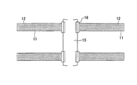
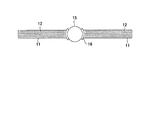
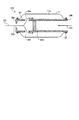
図2-1は、エアレーションノズルの平面図、図2-2は、エアレーションノズルの正面図、図3はエアレーションノズルの内部構造概略図である。
図2-1、図2-2に示すように、エアレーションノズル123は、基材の周囲を覆うゴム製の散気膜11に小さなスリット12が多数設けられたものであり、一般的には「ディフューザノズル」と呼ばれている。このようなエアレーションノズル123は、空気供給ラインL5から供給される空気122の圧力により散気膜11が膨張すると、スリット12が開いて略均等な大きさの微細気泡を多数流出させることができる。
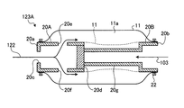
このため、一端20a側は、ヘッダ15及びフランジ16を貫通する空気導入口20cを介してヘッダ15内部と連通している。そして、支持体20の内部は、支持体20の軸方向の途中に設けた仕切板20dにより分割され、この仕切板20dにより空気の流通が阻止されている。さらに、この仕切板20dよりヘッダ15側となる支持体20の側面には、散気膜11の内周面と支持体外周面との間に、すなわち、散気膜11を加圧して膨張させる加圧空間11aへ空気122を流出させるための空気出口20e、20fが開口している。従って、ヘッダ15からエアレーションノズル123に流入する空気122は、図中に矢印で示すように、空気導入口20cから支持体20の内部へ流入した後、側面の空気出口20e、20fから加圧空間11aへ流出することとなる。
なお、締結部材22は、散気膜11を支持体20に固定するとともに、空気出口20e、20fから流入する空気が両端部から漏出することを防止するものである。
このような微細気泡の発生は、枝管L5A~5H及びヘッダ15を介して空気供給を受ける全てのエアレーションノズル123で実施される(図4、5参照)。
図4、図5は、本実施例に係るエアレーション装置の概略図である。
図4に示すように、本実施例に係るエアレーション装置120Aは、被処理水である希釈使用済海水(図示せず)中に浸漬され、希釈使用済海水中に微細気泡を発生させるエアレーション装置であって、空気122を吐出手段であるブロア121A~121Dにより供給する空気供給ラインL5と、水が含まれた空気が供給されるスリットを有する散気膜11を備えたエアレーションノズル123と、空気122の供給の一時的な停止を所定時間毎に制御する制御装置(図示せず)とを具備するものである。 また、空気供給ラインL5には、2基の冷却器131A、131Bと、2基のフィルタ132A、132Bとが各々設けられている。これにより、ブロア121A~121Dにより圧縮された空気は冷却され、次いで濾過されている。
なお、ブロアが4基あるのは、通常は3基で運転しており、その内の1基は予備としている。また、冷却器131A、131Bと、フィルタ132A、132Bとが各々2基あるのは、連続して運転する必要から、通常は片方のみで運転し、他方はメンテナンス用としている。
図11-1は、散気膜のスリットにおける、空気(飽和度の低い湿り空気)の流出と海水の浸入、および濃縮海水の状況を示す図である。図11-2は、散気膜のスリットにおける、空気の流出と海水の浸入、および濃縮海水の状況を示す図である。図11-3は、散気膜のスリットにおける、空気の流出と海水の浸入、濃縮海水及び析出物の状況を示す図である。
ここで、本発明において、スリット12とは、散気膜11に形成される切れ込みをいい、スリット12の間隙は空気が排出される通路となる。
この通路を形成するスリット壁面12aは、海水103が接触しているが、空気122の導入によって乾燥・濃縮され、濃縮海水103aとなり、その後スリット壁面に析出物103bが析出され、スリットの通路を閉塞するものとなる。
よって、この状態において、後述するように圧力変動を生じさせることにより、強制的に析出物を除去することで、長期間に亙っての運転が可能となる。
なお、このような状態においても、後述するように圧力変動を生じさせることにより、強制的に析出物を除去することができる。
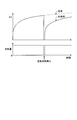
図6に示すように、所定時間毎に空気122の供給が停止するので、圧力変動が生じ(一時的に圧力0となる)、散気膜11の膨張が収縮するので、スリット12に析出した硫酸カルシウムの析出物が脱落し、スリット12が正常となる。
この結果、連続した運転における硫酸カルシウムの析出によるスリット12の詰まりやスリット12の間隙が狭くなることが防止され、散気膜11の圧力損失を防止できる。
これは、析出初期の早い段階で空気の供給を停止して、スリット12を通過する空気の圧力変動を行うことで、容易に析出物の脱落を生じさせることができるからである。
この結果、硫酸カルシウムの析出によるスリット12の詰まりやスリット12の間隙が狭くなることが防止され、散気膜11の圧力損失を防止できる。
このように、所定時間毎に空気122の供給が増大されるので、圧力変動が生じ(一時的に空気量が多くなる)、スリットを通過する空気の速度が増大するので、スリット12に析出した硫酸カルシウムの析出物が外部に排出され、スリット12が正常となる。
この結果、連続した運転における硫酸カルシウムの析出によるスリット12の詰まりやスリット12の間隙が狭くなることが防止され、散気膜11の圧力損失を防止できる。
これは、析出初期の早い段階で空気の供給を増大させ、スリット12を通過する空気の速度を増大させることで、容易に析出物を外部に排出させることができるからである。
よって、硫酸カルシウムの析出によるスリット12の詰まりやスリット12の間隙が狭くなることが防止され、散気膜11の圧力損失を防止できる。
また、ブロアの容量が不足の場合には、追加のブロアを用いて、スリット12から析出物を押出して一掃するような所定のパージ条件とするようにすればよい。
図8は本実施例に係るエアレーションノズル123Aの内部構造概略図である。
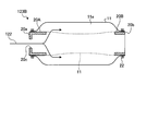
図8に示すように、本実施例に係るエアレーションノズル123Aは、内部に空気が導入される円筒状の基部側支持体20Aと、基部側支持体20Aよりも径が縮小され、仕切板20dを介して軸方向に設けられる中空筒体20gと、該中空筒体20gの他端に設けられ、前記基部側支持体20Aと略同一径の端部支持体20Bと、前記基部側支持体20Aと前記端部支持体20Bとを覆いつつ両端で締結部材22により締結されるチューブ状の散気膜11と、前記散気膜11に多数設けられたスリット(図示せず)と、前記基部側支持体20Aの側面に設けられ、散気膜11の内周面と支持体外周面との間の加圧空間11aへ導入された空気122を仕切板20dの手前側で流出させる空気出口20e、20fとを具備する。従って、ヘッダからエアレーションノズル123Aに流入する空気122は、図中に矢印で示すように、空気導入口20cから基部側支持体20Aの内部へ流入した後、側面の空気出口20e、20fから加圧空間11aへ流出することとなる。
図10は、本実施例に係るディスク状のエアレーションノズルの概略図である。
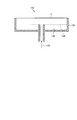
図10に示すように、ディスク状のエアレーションノズル133は、散気膜11の円筒状の支持体134の底部に析出物の収容部135を設けている。また、収容部135にはパンチングメタル136等の仕切りを設け、空気122の導入の流れを阻害しないようにしている。また、パンチングメタル136の下に析出物を落下させているので、空気122が供給された場合でも、舞い上がることはない。
12 スリット
100 海水排煙脱硫装置
102 排煙脱硫吸収塔
103 海水
103A 使用済海水
103B 希釈使用済海水
105 希釈混合槽
106 酸化槽
120A、120B エアレーション装置
123 エアレーションノズル
Claims (9)
- 被処理水中に浸漬され、被処理水中に微細気泡を発生させるエアレーション装置であって、
空気を吐出手段により供給する空気供給配管と、
前記空気が供給されるスリットを有する散気膜を備えたエアレーションノズルと、
空気の供給の一時的な停止を所定時間毎に制御する制御装置と
を具備することを特徴とするエアレーション装置。 - 被処理水中に浸漬され、被処理水中に微細気泡を発生させるエアレーション装置であって、
空気を吐出手段により供給する空気供給配管と、
前記空気が供給されるスリットを有する散気膜を備えたエアレーションノズルと、
空気の供給の一時的な増加を所定時間毎に制御する制御装置と
を具備することを特徴とするエアレーション装置。 - 請求項2において、
前記制御装置により空気の供給の一時的な増加をすると共に、水を空気供給配管に送る制御を行うことを特徴とするエアレーション装置。 - 請求項1において、
前記制御装置により空気の供給を一時的に停止し、水を空気供給配管に送る制御を行うことを特徴とするエアレーション装置。 - 請求項1乃至4のいずれか一つにおいて、
前記エアレーションノズルは、
内部に空気が導入される円筒状の基部側支持体と、
基部側支持体よりも径が縮小され、仕切板を介して軸方向に設けられる中空筒体と、
該中空筒体の他端に設けられ、前記基部側支持体と略同一径の端部支持体と、
前記基部側支持体と前記端部支持体を覆いつつ両端で締結されるチューブ状の散気膜と、
前記散気膜に多数設けられたスリットと、
前記基部側支持体の側面に設けられ、散気膜の内周面と支持体外周面との間の加圧空間へ導入された空気を仕切板の手前側で流出させる空気出口とを具備することを特徴とするエアレーション装置。 - 請求項1乃至4のいずれか一つにおいて、
前記エアレーションノズルは、
内部に空気が導入される円筒状の基部側支持体と、
基部側支持体と略同一径の端部支持体と、
基部側支持体と端部支持体を覆いつつ締結されるチューブ状の散気膜と、
前記散気膜に多数設けられたスリットとを具備することを特徴とするエアレーション装置。 - 海水を吸収剤として使用する脱硫塔と、
前記脱硫塔から排出された使用済海水を流して排水する水路と、
前記水路内に設置され、前記使用済海水中に微細気泡を発生して脱炭酸を行う請求項1乃至6のいずれか一つのエアレーション装置とを具備することを特徴とする海水排煙脱硫装置。 - 被処理水中に浸漬され、被処理水中に微細気泡を発生させるエアレーション装置を用い、
吐出手段により空気を供給する際、所定時間毎に、空気の供給の一時的な停止又は増大を実行し、目詰まりを防止することを特徴とするエアレーション装置の運転方法。 - 請求項8において、
前記空気の供給の一時的な停止又は増大を行う際、または単独で、水を空気供給配管に送ることを特徴とするエアレーション装置の運転方法。
Priority Applications (1)
| Application Number | Priority Date | Filing Date | Title |
|---|---|---|---|
| CN201180031714.3A CN102985371B (zh) | 2010-08-18 | 2011-01-19 | 通风装置及具备该装置的海水烟气脱硫装置、通风装置的运转方法 |
Applications Claiming Priority (2)
| Application Number | Priority Date | Filing Date | Title |
|---|---|---|---|
| JP2010-183498 | 2010-08-18 | ||
| JP2010183498A JP5582917B2 (ja) | 2010-08-18 | 2010-08-18 | エアレーション装置及びこれを備えた海水排煙脱硫装置、エアレーション装置の運転方法 |
Publications (1)
| Publication Number | Publication Date |
|---|---|
| WO2012023293A1 true WO2012023293A1 (ja) | 2012-02-23 |
Family
ID=45593021
Family Applications (1)
| Application Number | Title | Priority Date | Filing Date |
|---|---|---|---|
| PCT/JP2011/050891 Ceased WO2012023293A1 (ja) | 2010-08-18 | 2011-01-19 | エアレーション装置及びこれを備えた海水排煙脱硫装置、エアレーション装置の運転方法 |
Country Status (7)
| Country | Link |
|---|---|
| US (1) | US20120042783A1 (ja) |
| JP (1) | JP5582917B2 (ja) |
| CN (1) | CN102985371B (ja) |
| MY (1) | MY164130A (ja) |
| SA (1) | SA111320276B1 (ja) |
| TW (1) | TWI454429B (ja) |
| WO (1) | WO2012023293A1 (ja) |
Cited By (1)
| Publication number | Priority date | Publication date | Assignee | Title |
|---|---|---|---|---|
| CN110538545A (zh) * | 2019-09-29 | 2019-12-06 | 河北工业大学 | 一种膜曝气-吸收耦合式膜法海水烟气脱硫方法及装置 |
Families Citing this family (1)
| Publication number | Priority date | Publication date | Assignee | Title |
|---|---|---|---|---|
| US11291935B2 (en) * | 2018-04-13 | 2022-04-05 | Veolia Water Solutions & Technologies Support | Rotary disc filter having a backwash system that includes a compact nozzle support structure |
Citations (5)
| Publication number | Priority date | Publication date | Assignee | Title |
|---|---|---|---|---|
| JP2004033889A (ja) * | 2002-07-02 | 2004-02-05 | Sumitomo Heavy Ind Ltd | 散気方法及び散気システム |
| JP2004313938A (ja) * | 2003-04-16 | 2004-11-11 | Kobelco Eco-Solutions Co Ltd | 散気装置の目詰まり防止運転方法 |
| JP2005052773A (ja) * | 2003-08-06 | 2005-03-03 | Matsushita Electric Ind Co Ltd | 排水処理装置 |
| JP2009028572A (ja) * | 2007-07-24 | 2009-02-12 | Mitsubishi Heavy Ind Ltd | エアレーション装置 |
| JP2009106874A (ja) * | 2007-10-31 | 2009-05-21 | Hitachi Ltd | 反応槽及び散気装置 |
Family Cites Families (5)
| Publication number | Priority date | Publication date | Assignee | Title |
|---|---|---|---|---|
| US4243616A (en) * | 1979-02-15 | 1981-01-06 | Ronald Wyss | Air diffuser |
| JP3498402B2 (ja) * | 1995-02-06 | 2004-02-16 | 石川島播磨重工業株式会社 | 脱硫装置 |
| CN1308982A (zh) * | 2000-02-14 | 2001-08-22 | 况保宗 | 汶氏综合除so2除尘器 |
| TWM273946U (en) * | 2005-03-08 | 2005-09-01 | Shi-Lung Lai | Improvement of perforated plate structure |
| CN101821206B (zh) * | 2007-10-10 | 2012-06-27 | 东丽株式会社 | 细小气泡散气管、细小气泡散气装置和浸渍型膜分离装置 |
-
2010
- 2010-08-18 JP JP2010183498A patent/JP5582917B2/ja not_active Expired - Fee Related
-
2011
- 2011-01-19 CN CN201180031714.3A patent/CN102985371B/zh not_active Expired - Fee Related
- 2011-01-19 MY MYPI2012701076A patent/MY164130A/en unknown
- 2011-01-19 WO PCT/JP2011/050891 patent/WO2012023293A1/ja not_active Ceased
- 2011-03-16 SA SA111320276A patent/SA111320276B1/ar unknown
- 2011-03-18 TW TW100109466A patent/TWI454429B/zh not_active IP Right Cessation
- 2011-06-03 US US13/152,359 patent/US20120042783A1/en not_active Abandoned
Patent Citations (5)
| Publication number | Priority date | Publication date | Assignee | Title |
|---|---|---|---|---|
| JP2004033889A (ja) * | 2002-07-02 | 2004-02-05 | Sumitomo Heavy Ind Ltd | 散気方法及び散気システム |
| JP2004313938A (ja) * | 2003-04-16 | 2004-11-11 | Kobelco Eco-Solutions Co Ltd | 散気装置の目詰まり防止運転方法 |
| JP2005052773A (ja) * | 2003-08-06 | 2005-03-03 | Matsushita Electric Ind Co Ltd | 排水処理装置 |
| JP2009028572A (ja) * | 2007-07-24 | 2009-02-12 | Mitsubishi Heavy Ind Ltd | エアレーション装置 |
| JP2009106874A (ja) * | 2007-10-31 | 2009-05-21 | Hitachi Ltd | 反応槽及び散気装置 |
Cited By (1)
| Publication number | Priority date | Publication date | Assignee | Title |
|---|---|---|---|---|
| CN110538545A (zh) * | 2019-09-29 | 2019-12-06 | 河北工业大学 | 一种膜曝气-吸收耦合式膜法海水烟气脱硫方法及装置 |
Also Published As
| Publication number | Publication date |
|---|---|
| SA111320276B1 (ar) | 2014-11-19 |
| JP2012040492A (ja) | 2012-03-01 |
| TW201208986A (en) | 2012-03-01 |
| CN102985371A (zh) | 2013-03-20 |
| US20120042783A1 (en) | 2012-02-23 |
| TWI454429B (zh) | 2014-10-01 |
| CN102985371B (zh) | 2014-08-20 |
| JP5582917B2 (ja) | 2014-09-03 |
| MY164130A (en) | 2017-11-30 |
Similar Documents
| Publication | Publication Date | Title |
|---|---|---|
| JP5535861B2 (ja) | エアレーション装置及びこれを備えた海水排煙脱硫装置 | |
| JP5535823B2 (ja) | エアレーション装置及びこれを備えた海水排煙脱硫装置、エアレーション装置の運転方法 | |
| JP5535953B2 (ja) | エアレーション装置及びこれを備えた海水排煙脱硫装置、エアレーション装置の運転方法 | |
| JP5582952B2 (ja) | エアレーション装置及びこれを備えた海水排煙脱硫装置 | |
| JP5583037B2 (ja) | エアレーション装置及びこれを備えた海水排煙脱硫装置、エアレーション装置の運転方法 | |
| JP5582917B2 (ja) | エアレーション装置及びこれを備えた海水排煙脱硫装置、エアレーション装置の運転方法 | |
| JP5535817B2 (ja) | エアレーション装置及びこれを備えた海水排煙脱硫装置、エアレーション装置の加湿方法 | |
| JP5535824B2 (ja) | エアレーション装置及びこれを備えた海水排煙脱硫装置 | |
| JP2012236164A (ja) | エアレーション装置及びこれを備えた海水排煙脱硫装置、エアレーション装置の運転方法 | |
| JP2013022512A (ja) | エアレーション装置及び海水排煙脱硫装置 |
Legal Events
| Date | Code | Title | Description |
|---|---|---|---|
| WWE | Wipo information: entry into national phase |
Ref document number: 201180031714.3 Country of ref document: CN |
|
| 121 | Ep: the epo has been informed by wipo that ep was designated in this application |
Ref document number: 11817942 Country of ref document: EP Kind code of ref document: A1 |
|
| WWE | Wipo information: entry into national phase |
Ref document number: 10733/CHENP/2012 Country of ref document: IN |
|
| NENP | Non-entry into the national phase |
Ref country code: DE |
|
| WWE | Wipo information: entry into national phase |
Ref document number: 1201006770 Country of ref document: TH |
|
| 122 | Ep: pct application non-entry in european phase |
Ref document number: 11817942 Country of ref document: EP Kind code of ref document: A1 |