WO2012018147A1 - 인쇄 장치 - Google Patents
인쇄 장치 Download PDFInfo
- Publication number
- WO2012018147A1 WO2012018147A1 PCT/KR2010/005131 KR2010005131W WO2012018147A1 WO 2012018147 A1 WO2012018147 A1 WO 2012018147A1 KR 2010005131 W KR2010005131 W KR 2010005131W WO 2012018147 A1 WO2012018147 A1 WO 2012018147A1
- Authority
- WO
- WIPO (PCT)
- Prior art keywords
- printing
- web
- unit
- drying unit
- rewinder
- Prior art date
- Legal status (The legal status is an assumption and is not a legal conclusion. Google has not performed a legal analysis and makes no representation as to the accuracy of the status listed.)
- Ceased
Links
Images

Classifications
-
- B—PERFORMING OPERATIONS; TRANSPORTING
- B41—PRINTING; LINING MACHINES; TYPEWRITERS; STAMPS
- B41F—PRINTING MACHINES OR PRESSES
- B41F17/00—Printing apparatus or machines of special types or for particular purposes, not otherwise provided for
-
- B—PERFORMING OPERATIONS; TRANSPORTING
- B41—PRINTING; LINING MACHINES; TYPEWRITERS; STAMPS
- B41F—PRINTING MACHINES OR PRESSES
- B41F23/00—Devices for treating the surfaces of sheets, webs, or other articles in connection with printing
- B41F23/04—Devices for treating the surfaces of sheets, webs, or other articles in connection with printing by heat drying, by cooling, by applying powders
- B41F23/0403—Drying webs
-
- B—PERFORMING OPERATIONS; TRANSPORTING
- B41—PRINTING; LINING MACHINES; TYPEWRITERS; STAMPS
- B41F—PRINTING MACHINES OR PRESSES
- B41F23/00—Devices for treating the surfaces of sheets, webs, or other articles in connection with printing
- B41F23/04—Devices for treating the surfaces of sheets, webs, or other articles in connection with printing by heat drying, by cooling, by applying powders
- B41F23/0486—Particular types of dryers
Definitions
- the present invention relates to a printing apparatus, and more particularly, by applying a new type of common drying unit not used in the prior art, it is possible to prevent an increase in the number of installation units of the drying unit in proportion to the number of printing layers. Accordingly, the present invention relates to a printing apparatus capable of significantly reducing facility costs and facility spaces, as well as improving printing efficiency and minimizing general loss associated with printing.
- Roll to roll printing apparatuses which are widely used throughout the industry, are capable of high speed printing as compared to screen printers as a method of printing a film while drawing a film to be printed between a pair of rolls which are rotated relative to each other.
- Such a roll-to-roll printing apparatus includes an unwinder for releasing a web before printing, a printing unit for printing by a roll-to-roll method on a web released from the unwinder, and a drying for drying the web completed by the printing unit. It is common to consist of a unit and a rewinder which rewinds the web on which printing is completed by the printing unit.
- a first printing unit 1a, an unwinder 2, and a second printing unit 2b are directed from left to right on the drawing.
- the rewinder 3 are installed one after another, the primary drying unit 4a and the second printing unit (2) on the web W movement path between the first printing unit 1a and the second printing unit 1b.
- the secondary drying unit 4b is provided on the web moving path between 1b) and the rewinder 3.
- one layer is printed while the web W released from the unwinder 2 passes through the first printing unit 1a, and one layer printed matter is dried while passing through the first drying unit 4a.
- two layers are printed on the one-layer printed material which is continuously passed through the secondary printing unit 2b, and the two-layer printed material is dried while passing through the second drying unit 4b, and finally, the rewinder 3 Rewind to
- the first printing unit 1a, the unwinder 2, and the second printing unit (from the left side to the right side in the drawing) 1b), the third printing unit 1c and the rewinder 3 are installed in sequence, and the primary drying unit (on the web W moving path between the first printing unit 1a and the second printing unit 1b) 4a, the secondary drying unit 4b on the web W movement path between the second printing unit 1b and the third printing unit 1c, and the third printing unit 1c and the rewinder 3 It has a structure in which the tertiary drying unit (3c) is installed on the web (W) movement path between the ().
- one layer is printed while the web W released from the unwinder 2 passes through the first printing unit 1a, and one layer printed matter is dried while passing through the first drying unit 4a.
- two layers are printed on the one-layer printed matter dried while passing through the second printing unit 1b, and the two-layer printed matter is dried while passing through the second drying unit 4b.
- three layers are printed on the two-layer printed matter dried while passing through the third printing unit 3c, and the three-layer printed matter is dried while passing through the third drying unit 3c, and finally, the rewinder 3 Rewind
- An object of the present invention by applying a new type of common drying unit not used in the prior art, it is possible to prevent the number of installation of the drying unit increases in proportion to the number of printed layers, thereby reducing the installation cost and facility space
- the present invention provides a printing apparatus capable of greatly reducing the number of losses associated with a print job by improving the print job efficiency.
- the present invention by applying a new type of common drying unit not used in the prior art, it is possible to prevent the number of installation of the drying unit increases in proportion to the number of printed layers, thereby significantly reducing the installation cost and facility space. Not only can it reduce, but the efficiency of the print job can be improved to minimize the overall loss associated with the print job.
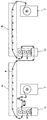
- FIG. 1 is an exemplary view of a two-layer printing apparatus according to the prior art.
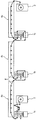
- FIG. 2 is another exemplary view of a three-layer printing apparatus according to the prior art.
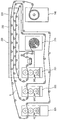
- FIG. 3 is a schematic configuration diagram of a printing apparatus according to a first embodiment of the present invention.
- FIG. 4 is a schematic configuration diagram of a printing apparatus according to a second embodiment of the present invention.
- the object is a plurality of printing units for sequentially laminating a predetermined print pattern on a web that is a print object; And a common drying unit disposed adjacent to the plurality of printing units, wherein the shared drying unit is dried while collectively passing through the web passing through the plurality of printing units.
- An unwinder for releasing said web toward a first first printing unit of said plurality of printing units; And a rewinder for rewinding the web where both printing and drying are completed.
- the unwinder, the plurality of printing units, the common drying unit and the rewinder may form a continuous virtual work line.
- the plurality of printing units may be disposed adjacent to each other, and the unwinder and the rewinder may be disposed adjacent to each other.
- the first web passing through the first first printing unit and towards the common drying unit may be dried while passing through the bottom in the shared drying unit, and the second passing through the second second printing unit and towards the common drying unit.
- the web may be dried while passing upwards in the common drying unit above the first web, and the nth web passing through the nth (n is natural water) printing unit and directed to the common drying unit is within the common drying unit. Can be dried while passing through the top.
- Each of the plurality of printing units may include a dispenser for supplying ink for forming the print pattern; A gravure roll on which ink from the dispenser is applied to the outer surface; And a pair of printing rolls that are transferred with ink from the gravure roll but are printed while the web is passed therebetween.
- the gravure roll is capable of being approached or spaced apart with respect to the pair of printing rolls.
- the common drying unit includes a unit body; And a heating member provided in the unit main body as a heater or an ultraviolet lamp.
- the unit body may be partitioned into a forced drying section and a natural drying section, and the heating member may be provided in the forced drying section.
- the unwinder may include an unwinder body; And an unwinding roll rotatably coupled to the unwinder body to substantially release the web and supply the web to the work line, wherein the rewinder comprises: a rewinder body; And a rewinding roll rotatably coupled to the rewinder body to print the completed web in the form of a roll.
- At least one feed nip roll provided on a virtual work line formed by the web and independently driven to continuously move the web from the unwinder toward the rewinder; And a plurality of tensionless rolls for adjusting tension of the web, which are disposed at several places of the work line.
- Embodiments described herein will be described with reference to cross-sectional and / or plan views, which are ideal exemplary views of the present invention.
- the thicknesses of films and regions are exaggerated for effective explanation of technical content. Therefore, the shape of the exemplary diagram may be modified by manufacturing techniques and / or tolerances. Accordingly, the embodiments of the present invention are not limited to the specific forms shown, but also include changes in forms generated according to manufacturing processes.
- the etched regions shown at right angles may be rounded or have a predetermined curvature.
- the regions illustrated in the figures have properties, and the shape of the regions illustrated in the figures is intended to illustrate a particular form of region of the device and is not intended to limit the scope of the invention.
- terms such as first and second are used to describe various components in various embodiments of the present specification, these components should not be limited by such terms. These terms are only used to distinguish one component from another.
- the embodiments described and illustrated herein also include complementary embodiments thereof.
- FIG. 3 is a schematic configuration diagram of a printing apparatus according to a first embodiment of the present invention.
- the printing apparatus of this embodiment uses a so-called roll to roll printing method for mass production of electronic devices using conductive ink.
- the scope of the present invention does not need to be limited thereto, and the printing apparatus of the present embodiment is flexible, including, for example, a film such as an electromagnetic interference (EMI) filter required in the flat panel display industry or similar IT industry. It can be applied to continuous printing on various films including touch screen panels and the like. Therefore, the web (W) to be described below may correspond to the various films described above.
- EMI electromagnetic interference
- the printing apparatus of this embodiment is a device for printing a two-layer, on the unwinder 110 for releasing the web (W) to be printed, and on the web (W) released from the unwinder 110.
- Two first and second printing units 121 and 122 for sequentially laminating a predetermined print pattern and the web W printed by the first and second printing units 121 and 122 are collectively passed through.
- the common drying unit 130 is dried while drying, and the rewinder 140 to rewind the web (W) is completed for both printing and drying.
- the unwinder 110, the first and second printing units 121 and 122, the common drying unit 130, and the rewinder 140 form a continuous virtual work line.
- the unwinder 110, the first and second printing units 121 and 122, the common drying unit 130, and the rewinder 140 are preferably gathered with each other for structural or efficiency reasons.
- first and second printing units 121 and 122 are arranged next to each other, and the unwinder 110 and the rewinder 140 are arranged next to each other, and the common drying unit (above or below) is disposed. 130 is being deployed.
- this structure may be a compact optimal structure, it can be changed to any number of other structures and arrangements, so the scope of the present invention is not necessarily limited to the drawings of FIG. 3.
- a plurality of feed nip rolls 150 and a plurality of tensionless forceless rolls 160 are provided on the virtual work line formed by the web W.
- the feed nip roll 150 is driven independently by the servomotor 151 and serves to continuously move the web W from the unwinder 110 toward the rewinder 140.
- a plurality of tensionless force-free rolls 160 are disposed at various places in the work line to adjust the tension of the web (W). While the feed nip roll 150 is a roll driven independently by the servomotor 151, the tensionless powerless roll 160 may be provided as a powerless roll to which a motor is not coupled.
- the unwinder 110 is rotatably coupled to the unwinder main body 111 and the unwinder main body 111 to unwind the web W, which is a printing object, and to supply the unwinding roll 112 to a work line. ).
- the rewinder 140 includes a rewinder main body 141 and a rewinding roll 142 rotatably coupled to the rewinder main body 141 so that the printed web W is wound in the form of a roll.
- the unwinding roll 112 and the rewinding roll 142 are applied in a so-called turret manner, ie a pair of rolls can be rotated by a central axis of rotation, the web (W)
- the new roll can be easily replaced in place of the unwinding roll 112 exhausted due to exhaustion of the unwinding roll 112 or the rewinding roll 142 in which the web W is wound.
- the first and second printing units 121, 122 have the same configuration. That is, the first and second printing units 121 and 122 may include a dispenser 123a and 123b for supplying ink for forming a print pattern, and a gravure roll 124a for applying ink from the dispenser 123a and 123b to an outer surface thereof. 124b and a pair of printing rolls 125a and 125b that receive ink from the gravure rolls 124a and 124b and are printed while the web W passes therebetween.
- a separate doctor blade is provided around the gravure rolls 124a and 124b so that the dispenser 123a and 123b may not be necessary when the ink is applied to the outer surface of the gravure rolls 124a and 124b. You can also remove it.
- the gravure rolls 124a and 124b when grooves are formed on the outer surfaces of the gravure rolls 124a and 124b, ink must enter only the grooves for pattern printing, but ink from the dispenser 123a and 123b is formed on the outer surfaces of the gravure rolls 124a and 124b. It is difficult to apply so as to enter only the groove. Therefore, after the dispensers 123a and 123b apply the ink to the entire outer surface area of the gravure rolls 124a and 124b, a separate doctor blade scrapes the outer surfaces of the gravure rolls 124a and 124b so that the ink is applied only to the recesses. Can be accommodated. Of course, this is just one example.
- the gravure rolls 124a and 124b may be driven to be approached or spaced apart from the printing rolls 125a and 125b.
- the ink from the dispensers 123a and 123b is applied to the gravure rolls 124a and 124b, and the ink from the gravure rolls 124a and 124b is transferred to the pair of printing rolls 125 so that a pair of printing rolls A predetermined pattern can be printed on the web W passing through the 125.
- the first and second printing units 121 and 122 are provided, the first printing pattern is printed on the web W through the first printing unit 121 and then the second printing pattern is printed on the upper surface thereof.
- the secondary printing pattern may be stacked while the printing unit 122 is printed.
- the common drying unit 130 is a part for drying the printed web (W). That is, immediately after the primary print pattern is printed on the web W passing through the first printing unit 121 or immediately after the secondary print pattern is printed on the web W passing through the second printing unit 122. Although the print patterns are not yet dry, it is difficult to rewind the rewinder 140 in this state. Therefore, it is necessary to dry the printing pattern immediately after the printing operation is performed, but the common drying unit 130 plays such a role.
- the common drying unit 130 may include a unit main body 131 and a heating member 132 provided in the unit main body 131 as a heater or an ultraviolet lamp, and the heating member 132. By the action of to dry the web (W) passing through the common drying unit 130.
- the drying may be continued by applying heat to the web W passing through the common drying unit 130, but in this case, damage to the web W may be caused, so that the unit body 131 of the common drying unit 130 may be damaged.
- the interior may be divided into approximately two or more spaces, and may be used as a forced drying section for performing forced dry by heat at the front and a natural drying section for naturally drying at the rear. In this case, the heating member 132 only needs to be provided in the forced drying section. Of course, this is an option and not necessarily.
- one common drying unit 130 is installed differently from the prior art, irrespective of the number of printing units 121 and 122, and is printed while passing through the plurality of first and second printing units 121 and 122.
- the web W is dried in common.
- both the web W on which the primary printing pattern is printed by the first printing unit 121 and the web W on which the secondary printing pattern is laminated and printed by the second printing unit 122 are collectively. Drying is carried out via a single common drying unit 130.
- this effect can provide a greater effect as the print layer increases as more than three layers rather than two-layer printing as in this embodiment.
- FIG. 4 is a schematic configuration diagram of a printing apparatus according to a second embodiment of the present invention.
- each of the third webs W3 laminated and printed again through the third third printing unit 223 is dried while all are collectively passed through a single common drying unit 230.
- the first web W1 is disposed at the bottom of the common drying unit 230
- the second web W2 is disposed above the first web W1
- the third web W3 is disposed at the top. It passes through the common drying unit 230.
- the heating unit 232 is located in the upper part of the unit body 231, and also because the web W can form a continuous virtual work line without tangling with each other only by having such an arrangement structure. to be.
- the present invention can be used for continuous printing on a variety of films including films required by the flat panel display industry or similar IT industries, such as electromagnetic interference (EMI) filters and flexible touch screen panels. .
- EMI electromagnetic interference
Landscapes
- Engineering & Computer Science (AREA)
- Mechanical Engineering (AREA)
- Rotary Presses (AREA)
Abstract
본 발명은 인쇄 장치에 관한 것으로서, 인쇄대상물인 웹 상에 소정의 인쇄 패턴(pattern)을 순차적으로 적층 인쇄하는 다수의 인쇄 유닛; 및 다수의 인쇄 유닛에 이웃하게 배치되며, 다수의 인쇄 유닛을 지나는 웹이 일괄적으로 경유하면서 건조되는 공용 건조 유닛을 포함하는 것을 특징으로 한다. 이에 의해, 종래기술에서 사용되지 않던 새로운 타입의 공용 건조 유닛을 적용함으로써 인쇄층의 개수에 비례하여 건조 유닛의 설치 대수가 증가하는 것을 방지할 수 있으며, 이에 따라 시설비용 및 시설공간을 대폭 감소시킬 수 있을 뿐만 아니라 인쇄 작업 능률을 향상시켜 인쇄 작업과 관련된 제반적인 로스(loss) 발생을 최소화할 수 있다.
Description
본 발명은, 인쇄 장치에 관한 것으로서, 보다 상세하게는, 종래기술에서 사용되지 않던 새로운 타입의 공용 건조 유닛을 적용함으로써 인쇄층의 개수에 비례하여 건조 유닛의 설치 대수가 증가하는 것을 방지할 수 있으며, 이에 따라 시설비용 및 시설공간을 대폭 감소시킬 수 있을 뿐만 아니라 인쇄 작업 능률을 향상시켜 인쇄 작업과 관련된 제반적인 로스(loss) 발생을 최소화할 수 있는 인쇄 장치에 관한 것이다.
산업 전반에 걸쳐 널리 사용되고 있는 롤투롤(Roll to Roll) 인쇄 장치는, 상대 회전되는 한 쌍의 롤 사이로 인쇄 대상의 필름을 인입시키면서 필름을 인쇄하는 방식으로서 스크린 프린터에 비해 고속 인쇄가 가능하다.
이러한 롤투롤 인쇄 장치는 인쇄 전 웹을 풀어주는 언와인더와, 언와인더에서 풀려져 나오는 웹에 롤투롤 방식에 의해 인쇄를 행하는 인쇄 유닛과, 인쇄 유닛에 의해 인쇄가 완료된 웹을 건조시키는 건조 유닛과, 인쇄 유닛에 의해 인쇄가 완료된 웹을 되감는 리와인더로 이루어지는 것이 일반적이다.
그런데, 종래의 롤투롤 인쇄 장치를 이용하여 2층 이상으로 적층 인쇄를 할 경우에는 적어도 2대의 인쇄 유닛이 설치되어야 하고, 또한 인쇄 유닛의 대수에 비례하여 건조 유닛 역시 같은 대수로 설치되어야 한다. 이는 아래의 도 1 및 도 2를 통해 확인할 수 있다.
먼저, 도 1을 참조하여 2층 인쇄를 예로 들면 종래의 2층 인쇄 장치의 경우, 도면상 좌측에서 우측을 향해 제1 인쇄 유닛(1a), 언와인더(2), 제2 인쇄 유닛(2b) 및 리와인더(3)가 차례로 설치되며, 제1 인쇄 유닛(1a)과 제2 인쇄 유닛(1b) 사이의 웹(W) 이동 경로 상에는 1차 건조 유닛(4a)이, 그리고 제2 인쇄 유닛(1b)과 리와인더(3)사이의 웹 이동 경로 상에는 2차 건조 유닛(4b)이 설치되는 구조를 갖는다.
이에 따라, 언와인더(2)에서 풀려져 나오는 웹(W)이 제1 인쇄 유닛(1a)을 통과하면서 1층이 인쇄되고, 제1 건조 유닛(4a)을 통과하면서 1층 인쇄물이 건조된다. 다음, 연속해서 2차 인쇄 유닛(2b)을 통과하면서 건조된 1층 인쇄물 위에 2층이 인쇄되고, 제2 건조 유닛(4b)을 통과하면서 2층 인쇄물이 건조된 후, 최종적으로 리와인더(3)에 되감긴다.
다음으로, 도 2를 참조하여 3층 인쇄를 예로 들면 종래의 3층 인쇄 장치의 경우, 도면상 좌측에서 우측을 향해 제1 인쇄 유닛(1a), 언와인더(2), 제2 인쇄 유닛(1b), 제3 인쇄 유닛(1c) 및 리와인더(3)가 차례로 설치되며, 제1 인쇄 유닛(1a)과 제2 인쇄 유닛(1b) 사이의 웹(W) 이동 경로 상에 1차 건조 유닛(4a)이, 제2 인쇄 유닛(1b)과 제3 인쇄 유닛(1c) 사이의 웹(W) 이동 경로 상에 2차 건조 유닛(4b)이, 그리고 제3 인쇄 유닛(1c)과 리와인더(3) 사이의 웹(W) 이동 경로 상에 3차 건조 유닛(3c)이 설치되는 구조를 갖는다.
이에 따라, 언와인더(2)에서 풀려져 나오는 웹(W)이 제1 인쇄 유닛(1a)을 통과하면서 1층이 인쇄되고, 제1 건조 유닛(4a)을 통과하면서 1층 인쇄물이 건조된다. 다음, 제2 인쇄 유닛(1b)을 통과하면서 건조된 1층 인쇄물 위에 2층이 인쇄되고, 제2 건조 유닛(4b)을 통과하면서 2층 인쇄물이 건조된다. 그런 다음, 제3 인쇄 유닛(3c)을 통과하면서 건조된 2층 인쇄물 위에 3층이 인쇄되고, 제3 건조 유닛(3c)을 통과하면서 3층 인쇄물이 건조된 후, 최종적으로 리와인더(3)에 되감긴다.
이처럼 종래의 인쇄 장치를 이용하여 웹(W) 상에 2개 층 이상을 적층 인쇄할 때는, 즉 웹(W) 상에 다수의 인쇄층을 형성할 때는 도 1 및 도 2와 같이 인쇄층의 개수만큼 건조 유닛이 설치되어야 하기 때문에 비용 상승의 요인을 이루고, 또한 각 유닛들의 점유 공간이 커지게 됨으로써 풋 프린트(foot print)가 증가되는 문제를 발생시킨다.
이러한 문제를 해결하기 위한 대안으로 건조가 빠른 잉크나 웹을 사용한다거나 건조온도를 조절하거나 그 이송 속도를 조절하는 등의 다양한 방법 등이 적용되기도 하지만 이러한 방법만으로는 근본적으로 시설비용 및 시설공간상 문제를 해소하기에 한계가 있으므로 이에 대한 대책이 요구된다.
본 발명의 목적은, 종래기술에서 사용되지 않던 새로운 타입의 공용 건조 유닛을 적용함으로써 인쇄층의 개수에 비례하여 건조 유닛의 설치 대수가 증가하는 것을 방지할 수 있으며, 이에 따라 시설비용 및 시설공간을 대폭 감소시킬 수 있을 뿐만 아니라 인쇄 작업 능률을 향상시켜 인쇄 작업과 관련된 제반적인 로스(loss) 발생을 최소화할 수 있는 인쇄 장치를 제공하는 것이다.
본 발명에 따르면, 종래기술에서 사용되지 않던 새로운 타입의 공용 건조 유닛을 적용함으로써 인쇄층의 개수에 비례하여 건조 유닛의 설치 대수가 증가하는 것을 방지할 수 있으며, 이에 따라 시설비용 및 시설공간을 대폭 감소시킬 수 있을 뿐만 아니라 인쇄 작업 능률을 향상시켜 인쇄 작업과 관련된 제반적인 로스(loss) 발생을 최소화할 수 있는 효과가 있다.
도 1은 종래기술에 따른 2층 인쇄 장치의 일 예시도이다.
도 2는 종래기술에 따른 3층 인쇄 장치의 다른 예시도이다.
도 3은 본 발명의 제1 실시예에 따른 인쇄 장치의 개략적인 구성도이다.
도 4는 본 발명의 제2 실시예에 따른 인쇄 장치의 개략적인 구성도이다.
상기 목적은, 인쇄대상물인 웹 상에 소정의 인쇄 패턴(pattern)을 순차적으로 적층 인쇄하는 다수의 인쇄 유닛; 및 상기 다수의 인쇄 유닛에 이웃하게 배치되며, 상기 다수의 인쇄 유닛을 지나는 상기 웹이 일괄적으로 경유하면서 건조되는 공용 건조 유닛을 포함하는 것을 특징으로 하는 인쇄 장치에 의해 달성된다.
여기서, 상기 다수의 인쇄 유닛 중에서 첫 번째의 제1 인쇄 유닛 쪽으로 상기 웹을 풀어주는 언와인더; 및 인쇄와 건조가 모두 완료된 웹을 되감는 리와인더를 더 포함할 수 있다.
상기 언와인더, 상기 다수의 인쇄 유닛, 상기 공용 건조 유닛 및 상기 리와인더는 연속된 가상의 작업라인을 형성할 수 있다.
상기 다수의 인쇄 유닛은 상호간 이웃하게 배치되고, 상기 언와인더와 상기 리와인더는 상호간 이웃하게 배치될 수 있다.
첫 번째 제1 인쇄 유닛을 지나 상기 공용 건조 유닛으로 향하는 제1 웹은 상기 공용 건조 유닛 내에서 가장 아래쪽을 통과하면서 건조될 수 있으며, 두 번째 제2 인쇄 유닛을 지나 상기 공용 건조 유닛으로 향하는 제2 웹은 상기 공용 건조 유닛 내에서 상기 제1 웹보다 위쪽을 통과하면서 건조될 수 있으며, n번째(n은 자연수임) 인쇄 유닛을 지나 상기 공용 건조 유닛으로 향하는 n번째 웹은 상기 공용 건조 유닛 내에서 가장 위쪽을 통과하면서 건조될 수 있다.
상기 다수의 인쇄 유닛 각각은, 상기 인쇄 패턴의 형성을 위한 잉크를 공급하는 디스펜서; 상기 디스펜서로부터의 잉크가 외면으로 도포되는 그라비아 롤; 및 상기 그라비아 롤로부터의 잉크를 전이 받되 그 사이로 상기 웹이 지나가면서 인쇄되는 한 쌍의 인쇄롤을 포함할 수 있다.
상기 그라비아 롤은 상기 한 쌍의 인쇄롤에 대하여 접근 또는 이격 구동 가능하다.
상기 공용 건조 유닛은, 유닛 본체; 및 상기 유닛 본체 내에 마련되되 히터(heater) 혹은 자외선램프(lamp)로서의 가열부재를 포함할 수 있다.
상기 유닛 본체는 내부가 강제 건조 구간 및 자연 건조 구간으로 구획 가능하며, 상기 가열부재는 상기 강제 건조 구간에 마련될 수 있다.
상기 언와인더는, 언와인더 본체; 및 상기 언와인더 본체에 회전 가능하게 결합되어 실질적으로 상기 웹을 풀어 상기 작업라인으로 공급하는 언와인딩 롤을 포함할 수 있으며, 상기 리와인더는, 리와인더 본체; 및 상기 리와인더 본체에 회전 가능하게 결합되어 인쇄 완료된 웹이 롤(roll)의 형태로 권취되는 리와인딩 롤을 포함할 수 있다.
상기 웹에 의해 형성되는 가상의 작업라인 상에 마련되며, 독립적으로 구동되면서 상기 웹을 상기 언와인더에서 상기 리와인더 쪽으로 연속 이동시키는 적어도 하나의 피드 닙 롤(feed nip roll); 및 상기 작업라인의 군데군데에 배치되어 상기 웹의 장력을 조절하는 다수의 장력 조절용 무동력 롤을 더 포함할 수 있다.
이상의 본 발명의 목적들, 다른 목적들, 특징들 및 이점들은 첨부된 도면과 관련된 이하의 바람직한 실시예들을 통해서 쉽게 이해될 것이다. 그러나 본 발명은 여기서 설명되는 실시예들에 한정되지 않고 다른 형태로 구체화될 수도 있다. 오히려, 여기서 소개되는 실시예들은 개시된 내용이 철저하고 완전해질 수 있도록 그리고 당업자에게 본 발명의 사상이 충분히 전달될 수 있도록 하기 위해 제공되는 것이다.
본 명세서에서, 어떤 구성요소가 다른 구성요소 상에 있다고 언급되는 경우에 그것은 다른 구성요소 상에 직접 형성될 수 있거나 또는 그들 사이에 제 3의 구성요소가 개재될 수도 있다는 것을 의미한다. 또한 도면들에 있어서, 구성요소들의 두께는 기술적 내용의 효과적인 설명을 위해 과장된 것이다.
본 명세서에서 기술하는 실시예들은 본 발명의 이상적인 예시도인 단면도 및/또는 평면도들을 참고하여 설명될 것이다. 도면들에 있어서, 막 및 영역들의 두께는 기술적 내용의 효과적인 설명을 위해 과장된 것이다. 따라서 제조 기술 및/또는 허용 오차 등에 의해 예시도의 형태가 변형될 수 있다. 따라서 본 발명의 실시예들은 도시된 특정 형태로 제한되는 것이 아니라 제조 공정에 따라 생성되는 형태의 변화도 포함하는 것이다. 예를 들면, 직각으로 도시된 식각 영역은 라운드지거나 소정 곡률을 가지는 형태일 수 있다. 따라서 도면에서 예시된 영역들은 속성을 가지며, 도면에서 예시된 영역들의 모양은 소자의 영역의 특정 형태를 예시하기 위한 것이며 발명의 범주를 제한하기 위한 것이 아니다. 본 명세서의 다양한 실시예들에서 제1, 제2 등의 용어가 다양한 구성요소들을 기술하기 위해서 사용되었지만, 이들 구성요소들이 이 같은 용어들에 의해서 한정되어서는 안 된다. 이들 용어들은 단지 어느 구성요소를 다른 구성요소와 구별시키기 위해서 사용되었을 뿐이다. 여기에 설명되고 예시되는 실시예들은 그것의 상보적인 실시예들도 포함한다.
본 명세서에서 사용된 용어는 실시예들을 설명하기 위한 것이며 본 발명을 제한하고자 하는 것은 아니다. 본 명세서에서, 단수형은 문구에서 특별히 언급하지 않는 한 복수형도 포함한다. 명세서에서 사용되는 '포함한다(comprises)' 및/또는 '포함하는(comprising)'은 언급된 구성요소는 하나 이상의 다른 구성요소의 존재 또는 추가를 배제하지 않는다.
이하, 도면을 참조하여 본 발명을 상세히 설명하도록 한다. 아래의 특정 실시예들을 기술하는데 있어서, 여러 가지의 특정적인 내용들은 발명을 더 구체적으로 설명하고 이해를 돕기 위해 작성되었다. 하지만 본 발명을 이해할 수 있을 정도로 이 분야의 지식을 갖고 있는 독자는 이러한 여러 가지의 특정적인 내용들이 없어도 사용될 수 있다는 것을 인지할 수 있다. 어떤 경우에는, 발명을 기술하는 데 있어서 흔히 알려졌으면서 발명과 크게 관련 없는 부분들은 본 발명을 설명하는데 있어 별 이유 없이 혼돈이 오는 것을 막기 위해 기술하지 않음을 미리 언급해 둔다.
도 3은 본 발명의 제1 실시예에 따른 인쇄 장치의 개략적인 구성도이다.
이 도면에 도시된 바와 같이, 본 실시예의 인쇄 장치는, 전도성 잉크를 사용하여 전자소자를 대량으로 생산하기 위한 소위 롤투롤(Roll to Roll) 인쇄 방식을 이용한 것이다. 물론, 본 발명의 권리범위가 이에 제한될 필요는 없으며, 본 실시예의 인쇄 장치는 예컨대, 평판디스플레이 산업이나 혹은 그와 유사한 IT 산업에서 요구되는 필름, 예컨대 EMI(electromagnetic interference) 필터를 비롯하여 플랙서블한 터치스크린 패널 등을 포함하는 다양한 필름에 대해 연속적인 인쇄에 적용될 수 있다. 따라서 이하에서 설명할 웹(W)이란 전술한 다양한 필름에 해당될 수 있다.
이러한 본 실시예의 인쇄 장치는 2층을 인쇄하기 위한 장비로서, 인쇄대상물인 웹(W)을 풀어주는 언와인더(110)와, 언와인더(110)로부터 풀려져 나오는 웹(W) 상에 소정의 인쇄 패턴(pattern)을 순차적으로 적층 인쇄하는 2대의 제1 및 제2 인쇄 유닛(121,122)과, 제1 및 제2 인쇄 유닛(121,122)에 의해 인쇄된 웹(W)이 일괄적으로 경유하면서 건조되는 공용 건조 유닛(130)과, 인쇄와 건조가 모두 완료된 웹(W)을 되감는 리와인더(140)를 포함한다.
도면에 도시된 바와 같이, 언와인더(110), 제1 및 제2 인쇄 유닛(121,122), 공용 건조 유닛(130) 및 리와인더(140)는 연속된 가상의 작업라인을 형성한다. 이때, 언와인더(110), 제1 및 제2 인쇄 유닛(121,122), 공용 건조 유닛(130) 및 리와인더(140)는 상호간 모여 있는 것이 구조상 또는 효율상 바람직하다. 특히, 공용 건조 유닛(130)과 제1 및 제2 인쇄 유닛(121,122)은 좀 더 가까이에 이웃되게 배치되는 것이 효율상 바람직할 수 있다.
이에 더하여 본 실시예의 경우, 제1 및 제2 인쇄 유닛(121,122)이 상호 이웃하게, 그리고 언와인더(110)와 리와인더(140)가 상호 이웃하게 배치되고, 그 상부 혹은 하부로 공용 건조 유닛(130)이 배치되고 있다. 이러한 구조가 콤팩트한 최적의 구조일 수도 있겠으나 다른 구조 및 배열로도 얼마든지 변경이 가능하므로 도 3의 도면에 본 발명의 권리범위가 제한될 필요는 없다.
웹(W)에 의해 형성되는 가상의 작업라인 상에는 다수의 피드 닙 롤(150, feed nip roll)과, 다수의 장력 조절용 무동력 롤(160)이 마련된다.
피드 닙 롤(150)은 서보모터(151)에 의해 독립적으로 구동되면서 웹(W)을 언와인더(110)에서 리와인더(140) 쪽으로 연속 이동시키는 역할을 한다.
그리고 다수의 장력 조절용 무동력 롤(160)은 작업라인의 군데군데에 배치되어 웹(W)의 장력을 조절한다. 피드 닙 롤(150)이 서보모터(151)에 의해 독립적으로 구동되는 롤인데 반해 장력 조절용 무동력 롤(160)은 모터가 결합되지 않은 무동력 롤로 마련될 수 있다.
언와인더(110)는 언와인더 본체(111)와, 언와인더 본체(111)에 회전 가능하게 결합되어 실질적으로 인쇄대상물인 웹(W)을 풀어 작업라인으로 공급하는 언와인딩 롤(112)을 구비한다.
그리고 리와인더(140)는 리와인더 본체(141)와, 리와인더 본체(141)에 회전 가능하게 결합되어 인쇄 완료된 웹(W)이 롤(roll)의 형태로 권취되는 리와인딩 롤(142)을 구비한다.
선택사항이기는 하지만 언와인딩 롤(112)과 리와인딩 롤(142)을 소위, 터렛(turret) 방식, 즉 중앙의 회전축에 의해 한 쌍의 롤이 회전될 수 있는 방식으로 적용할 경우에는 웹(W)이 다 사용되어 소진된 언와인딩 롤(112)의 자리에, 혹은 웹(W)이 다 감긴 리와인딩 롤(142)의 자리에 새로운 롤(roll)을 손쉽게 교체할 수 있기 때문에 연속 작업이 가능해지고, 또한 롤의 교체에 따른 시간적인 로스(loss) 발생을 최소화시킬 수 있는 장점이 있을 것이다.
제1 및 제2 인쇄 유닛(121,122)은 동일한 구성을 갖는다. 즉 제1 및 제2 인쇄 유닛(121,122)은, 인쇄 패턴의 형성을 위한 잉크를 공급하는 디스펜서(123a,123b)와, 디스펜서(123a,123b)로부터의 잉크가 외면으로 도포되는 그라비아 롤(124a,124b)과, 그라비아 롤(124a,124b)로부터의 잉크를 전이 받되 그 사이로 웹(W)이 지나가면서 인쇄되는 한 쌍의 인쇄롤(125a,125b)을 구비한다.
자세히 도시하지는 않았지만 그라비아 롤(124a,124b)의 주변에는 별도의 닥터 블레이드(doctor blade)가 마련되어 디스펜서(123a,123b)가 그라비아 롤(124a,124b)의 외면으로 잉크를 도포했을 때 필요 없는 부분을 제거할 수도 있다.
예컨대, 그라비아 롤(124a,124b)의 외면에 요홈부가 형성되는 경우, 패턴 인쇄를 위해서는 잉크가 요홈부에만 들어가야 하지만 디스펜서(123a,123b)로부터의 잉크가 그라비아 롤(124a,124b)의 외면에 형성된 요홈부에만 들어가도록 도포하기는 곤란하다. 때문에, 디스펜서(123a,123b)가 그라비아 롤(124a,124b)의 외면 전영역으로 잉크를 도포하도록 한 후에, 별도의 닥터 블레이드가 그라비아 롤(124a,124b)의 외면을 긁어냄으로써 잉크가 요홈부에만 수용되도록 할 수 있다. 물론, 이는 하나에 예에 불과하다. 그리고 그라비아 롤(124a,124b)은 인쇄롤(125a,125b)에 대해 접근 또는 이격 가능하게 구동될 수도 있다.
이에, 디스펜서(123a,123b)로부터의 잉크가 그라비아 롤(124a,124b)로 도포되고, 그라비아 롤(124a,124b)로부터의 잉크가 한 쌍의 인쇄롤(125)로 전이됨으로써 한 쌍의 인쇄롤(125) 사이를 통과하는 웹(W) 상에 소정의 패턴이 인쇄될 수 있게 된다. 특히, 본 실시예의 경우에는 2개의 제1 및 제2 인쇄 유닛(121,122)이 마련되므로 제1 인쇄 유닛(121)을 통해 웹(W) 상에 1차 인쇄 패턴이 인쇄되고 나서 그 상면으로 제2 인쇄 유닛(122)을 통해 2차 인쇄 패턴이 적층되면서 인쇄될 수 있다.
공용 건조 유닛(130)은 인쇄된 웹(W)을 건조시키는 부분이다. 즉 제1 인쇄 유닛(121)을 지나는 웹(W) 상에 1차 인쇄 패턴이 인쇄된 직후나, 제2 인쇄 유닛(122)을 지나는 웹(W) 상에 2차 인쇄 패턴이 인쇄된 직후에는 인쇄 패턴들이 아직 마르지 않은 상태인데, 이 상태로 리와인더(140)에 되감기면 곤란하다. 따라서 인쇄 작업이 진행된 직후에는 인쇄 패턴을 건조시킬 필요가 있는데 이러한 역할을 공용 건조 유닛(130)이 담당한다.
공용 건조 유닛(130)은, 유닛 본체(131)와, 유닛 본체(131) 내에 마련되되 히터(heater) 혹은 자외선램프(lamp)로서의 가열부재(132)를 구비할 수 있으며, 가열부재(132)의 작용에 의해 공용 건조 유닛(130)을 지나는 웹(W)을 건조시킨다.
이때, 공용 건조 유닛(130)을 지나는 웹(W)에 계속해서 열을 가하여 건조시켜도 무방하지만 이러한 경우 웹(W)의 손상이 야기될 수도 있으므로 공용 건조 유닛(130)의 유닛 본체(131)의 내부는 대략 2개 이상의 공간으로 나뉘어 앞 쪽에서는 열에 의한 강제 건조를 실시하는 강제 건조 구간으로, 그리고 뒤 쪽에서는 자연 건조시키는 자연 건조 구간으로 사용될 수도 있다. 이러한 경우, 가열부재(132)는 강제 건조 구간에만 마련되면 된다. 물론, 이러한 사항은 하나의 선택 사항이며 반드시 그러할 필요는 없다.
한편, 본 실시예에서 공용 건조 유닛(130)은 종래와 달리, 즉 인쇄 유닛(121,122)들의 개수와 무관하게 한 개 설치되며, 다수의 제1 및 제2 인쇄 유닛(121,122)을 지나면서 인쇄된 웹(W)을 공용으로 건조시킨다.
다시 말해, 제1 인쇄 유닛(121)에 의해 1차 인쇄 패턴이 인쇄된 웹(W)이나 제2 인쇄 유닛(122)에 의해 2차 인쇄 패턴이 적층 인쇄된 웹(W) 모두는 일괄적으로 단일의 공용 건조 유닛(130)을 경유하면서 건조된다.
이처럼 본 실시예의 경우에는 단일의 공용 건조 유닛(130)만으로도 건조 효과를 제공할 수 있기 때문에 도 1 및 도 2에 도시된 종래의 인쇄 장치와는 달리 시설비용 및 시설공간을 대폭 감소시킬 수 있을 뿐만 아니라 인쇄 작업 능률을 향상시켜 인쇄 작업과 관련된 제반적인 로스(loss) 발생을 최소화할 수 있게 된다.
특히, 이러한 효과는 본 실시예처럼 2층 인쇄가 아닌 3층 이상으로 그 인쇄층이 증가하면 증가할수록 더 큰 효과를 제공할 수 있다.
이와 같이, 본 실시예에 따르면, 종래기술에서 사용되지 않던 새로운 타입의 공용 건조 유닛(130)을 적용함으로써 인쇄층의 개수에 비례하여 건조 유닛의 설치 대수가 증가하는 것을 방지할 수 있으며, 이에 따라 시설비용 및 시설공간을 대폭 감소시킬 수 있을 뿐만 아니라 인쇄 작업 능률을 향상시켜 인쇄 작업과 관련된 제반적인 로스(loss) 발생을 최소화할 수 있게 된다.
도 4는 본 발명의 제2 실시예에 따른 인쇄 장치의 개략적인 구성도이다.
본 실시예의 경우, 도 3과는 달리 3개의 제1 내지 제3 인쇄 유닛(221,222,223)과, 언와인더(210), 그리고 리와인더(240)가 마련된다. 이들의 구성은 전술한 실시예의 것으로 대체한다.
이처럼 3개의 제1 내지 제3 인쇄 유닛(221,222,223)이 마련되어 웹(W) 상에 적층 인쇄를 진행하는 경우일지라도, 하나의 공용 건조 유닛(230)만이 마련되면 그것으로 충분하다.
즉 언와인더(210)로부터 첫 번째 제1 인쇄 유닛(221)을 지나면서 인쇄된 제1 웹(W1)이나, 두 번째 제2 인쇄 유닛(222)을 지나면서 적층 인쇄된 제2 웹(W2)이나, 세 번째 제3 인쇄 유닛(223)을 지나면서 다시 적층 인쇄된 제3 웹(W3) 각각은 모두가 일괄적으로 단일의 공용 건조 유닛(230)을 경유하면서 건조된다.
이때, 공용 건조 유닛(230) 내에서 제1 웹(W1)은 가장 아래쪽에, 제2 웹(W2)은 제1 웹(W1)보다 위쪽에, 그리고 제3 웹(W3)은 가장 위쪽에 배치되어 공용 건조 유닛(230)을 통과한다. 이는 가열유닛(232)이 유닛 본체(231) 내의 상부에 위치되고 있기 때문이기도 하고, 또한 이와 같은 배열 구조를 가져야만 웹(W)이 서로 엉키지 않고 연속된 가상의 작업라인을 형성할 수 있기 때문이다.
본 실시예와 같이 구성하더라도 종래기술에서 사용되지 않던 새로운 타입의 공용 건조 유닛(230)을 적용함으로써 인쇄층의 개수에 비례하여 공용 건조 유닛(230)의 설치 대수가 증가하는 것을 방지할 수 있으며, 이에 따라 시설비용 및 시설공간을 대폭 감소시킬 수 있을 뿐만 아니라 인쇄 작업 능률을 향상시켜 인쇄 작업과 관련된 제반적인 로스(loss) 발생을 최소화할 수 있게 된다.
이와 같이 본 발명은 기재된 실시예에 한정되는 것이 아니고, 본 발명의 사상 및 범위를 벗어나지 않고 다양하게 수정 및 변형할 수 있음은 이 기술의 분야에서 통상의 지식을 가진 자에게 자명하다. 따라서 그러한 수정예 또는 변형예들은 본 발명의 특허청구범위에 속한다 하여야 할 것이다.
본 발명은, 평판디스플레이 산업이나 혹은 그와 유사한 IT 산업에서 요구되는 필름, 예컨대 EMI(electromagnetic interference) 필터를 비롯하여 플랙서블한 터치스크린 패널 등을 포함하는 다양한 필름에 대해 연속적인 인쇄 시 이용될 수 있다.
Claims (11)
- 인쇄대상물인 웹 상에 소정의 인쇄 패턴(pattern)을 순차적으로 적층 인쇄하는 다수의 인쇄 유닛; 및상기 다수의 인쇄 유닛에 이웃하게 배치되며, 상기 다수의 인쇄 유닛을 지나는 상기 웹이 일괄적으로 경유하면서 건조되는 공용 건조 유닛을 포함하는 것을 특징으로 하는 인쇄 장치.
- 제1항에 있어서,상기 다수의 인쇄 유닛 중에서 첫 번째의 제1 인쇄 유닛 쪽으로 상기 웹을 풀어주는 언와인더; 및인쇄와 건조가 모두 완료된 웹을 되감는 리와인더를 더 포함하는 것을 특징으로 하는 인쇄 장치.
- 제2항에 있어서,상기 언와인더, 상기 다수의 인쇄 유닛, 상기 공용 건조 유닛 및 상기 리와인더는 연속된 가상의 작업라인을 형성하는 것을 특징으로 하는 인쇄 장치.
- 제3항에 있어서,상기 다수의 인쇄 유닛은 상호간 이웃하게 배치되고, 상기 언와인더와 상기 리와인더는 상호간 이웃하게 배치되는 것을 특징으로 하는 인쇄 장치.
- 제1항에 있어서,첫 번째 제1 인쇄 유닛을 지나 상기 공용 건조 유닛으로 향하는 제1 웹은 상기 공용 건조 유닛 내에서 가장 아래쪽을 통과하면서 건조될 수 있으며,두 번째 제2 인쇄 유닛을 지나 상기 공용 건조 유닛으로 향하는 제2 웹은 상기 공용 건조 유닛 내에서 상기 제1 웹보다 위쪽을 통과하면서 건조될 수 있으며,n번째(n은 자연수임) 인쇄 유닛을 지나 상기 공용 건조 유닛으로 향하는 n번째 웹은 상기 공용 건조 유닛 내에서 가장 위쪽을 통과하면서 건조되는 것을 특징으로 하는 인쇄 장치.
- 제1항에 있어서,상기 다수의 인쇄 유닛 각각은,상기 인쇄 패턴의 형성을 위한 잉크를 공급하는 디스펜서;상기 디스펜서로부터의 잉크가 외면으로 도포되는 그라비아 롤; 및상기 그라비아 롤로부터의 잉크를 전이 받되 그 사이로 상기 웹이 지나가면서 인쇄되는 한 쌍의 인쇄롤을 포함하는 것을 특징으로 하는 인쇄 장치.
- 제6항에 있어서,상기 그라비아 롤은 상기 한 쌍의 인쇄롤에 대하여 접근 또는 이격 구동 가능한 것을 특징으로 하는 인쇄 장치.
- 제1항에 있어서,상기 공용 건조 유닛은,유닛 본체; 및상기 유닛 본체 내에 마련되되 히터(heater) 혹은 자외선램프(lamp)로서의 가열부재를 포함하는 것을 특징으로 하는 인쇄 장치.
- 제8항에 있어서,상기 유닛 본체는 내부가 강제 건조 구간 및 자연 건조 구간으로 구획 가능하며,상기 가열부재는 상기 강제 건조 구간에 마련되는 것을 특징으로 하는 인쇄 장치.
- 제2항에 있어서,상기 언와인더는,언와인더 본체; 및상기 언와인더 본체에 회전 가능하게 결합되어 실질적으로 상기 웹을 풀어 상기 작업라인으로 공급하는 언와인딩 롤을 포함하며,상기 리와인더는,리와인더 본체; 및상기 리와인더 본체에 회전 가능하게 결합되어 인쇄 완료된 웹이 롤(roll)의 형태로 권취되는 리와인딩 롤을 포함하는 것을 특징으로 하는 인쇄 장치.
- 제2항에 있어서,상기 웹에 의해 형성되는 가상의 작업라인 상에 마련되며, 독립적으로 구동되면서 상기 웹을 상기 언와인더에서 상기 리와인더 쪽으로 연속 이동시키는 적어도 하나의 피드 닙 롤(feed nip roll); 및상기 작업라인의 군데군데에 배치되어 상기 웹의 장력을 조절하는 다수의 장력 조절용 무동력 롤을 더 포함하는 것을 특징으로 하는 인쇄 장치.
Priority Applications (1)
| Application Number | Priority Date | Filing Date | Title |
|---|---|---|---|
| PCT/KR2010/005131 WO2012018147A1 (ko) | 2010-08-05 | 2010-08-05 | 인쇄 장치 |
Applications Claiming Priority (1)
| Application Number | Priority Date | Filing Date | Title |
|---|---|---|---|
| PCT/KR2010/005131 WO2012018147A1 (ko) | 2010-08-05 | 2010-08-05 | 인쇄 장치 |
Publications (1)
| Publication Number | Publication Date |
|---|---|
| WO2012018147A1 true WO2012018147A1 (ko) | 2012-02-09 |
Family
ID=45559636
Family Applications (1)
| Application Number | Title | Priority Date | Filing Date |
|---|---|---|---|
| PCT/KR2010/005131 Ceased WO2012018147A1 (ko) | 2010-08-05 | 2010-08-05 | 인쇄 장치 |
Country Status (1)
| Country | Link |
|---|---|
| WO (1) | WO2012018147A1 (ko) |
Cited By (4)
| Publication number | Priority date | Publication date | Assignee | Title |
|---|---|---|---|---|
| CN106004015A (zh) * | 2016-04-19 | 2016-10-12 | 无锡徐达防伪科技有限公司 | 3d霓彩光变印刷用全自动生产线及其生产工艺 |
| CN106032088A (zh) * | 2015-03-17 | 2016-10-19 | 金红叶纸业集团有限公司 | 一种印刷设备 |
| CN108001037A (zh) * | 2017-04-17 | 2018-05-08 | 东莞市锐泽创艺新材料有限公司 | 一种纸张、薄膜印刷复合剥离转移复合压纹切张生产设备 |
| CN110667235A (zh) * | 2019-09-16 | 2020-01-10 | 林金标 | 导带式无介质转移印花装置及其印花工艺 |
Citations (9)
| Publication number | Priority date | Publication date | Assignee | Title |
|---|---|---|---|---|
| JPS61108554A (ja) * | 1984-11-01 | 1986-05-27 | Shinichi Yamazaki | 多色刷印刷装置 |
| JPH0852405A (ja) * | 1994-08-11 | 1996-02-27 | Dainippon Printing Co Ltd | 乾燥ユニット及び塗工装置 |
| JPH08158297A (ja) * | 1994-12-07 | 1996-06-18 | Nippon Paper Ind Co Ltd | 塗被紙 |
| KR20060130850A (ko) * | 2005-06-09 | 2006-12-20 | 조성경 | 가구용 및 인테리어용 판넬에 사용되는 무늬지 제조 방법 |
| KR100687651B1 (ko) * | 2006-02-13 | 2007-02-27 | 주식회사 모텍스 | 친환경적인 라벨 및 스티커 원단의 생산 시스템 |
| JP2007532354A (ja) * | 2004-04-13 | 2007-11-15 | エム・アー・エヌ・ローラント・ドルックマシーネン・アクチエンゲゼルシャフト | エンボス装置 |
| KR20080071873A (ko) * | 2007-02-08 | 2008-08-05 | 준 호 정 | 종이 염색과 그라비아 인쇄 및 건조 기능을 가지는 종이염색장치 |
| KR100866597B1 (ko) * | 2007-06-13 | 2008-11-03 | 한국기계연구원 | 인쇄용 건조장치 |
| KR20100067432A (ko) * | 2008-12-11 | 2010-06-21 | 한국기계연구원 | 인쇄용지 자동공급기를 갖는 인쇄장치 |
-
2010
- 2010-08-05 WO PCT/KR2010/005131 patent/WO2012018147A1/ko not_active Ceased
Patent Citations (9)
| Publication number | Priority date | Publication date | Assignee | Title |
|---|---|---|---|---|
| JPS61108554A (ja) * | 1984-11-01 | 1986-05-27 | Shinichi Yamazaki | 多色刷印刷装置 |
| JPH0852405A (ja) * | 1994-08-11 | 1996-02-27 | Dainippon Printing Co Ltd | 乾燥ユニット及び塗工装置 |
| JPH08158297A (ja) * | 1994-12-07 | 1996-06-18 | Nippon Paper Ind Co Ltd | 塗被紙 |
| JP2007532354A (ja) * | 2004-04-13 | 2007-11-15 | エム・アー・エヌ・ローラント・ドルックマシーネン・アクチエンゲゼルシャフト | エンボス装置 |
| KR20060130850A (ko) * | 2005-06-09 | 2006-12-20 | 조성경 | 가구용 및 인테리어용 판넬에 사용되는 무늬지 제조 방법 |
| KR100687651B1 (ko) * | 2006-02-13 | 2007-02-27 | 주식회사 모텍스 | 친환경적인 라벨 및 스티커 원단의 생산 시스템 |
| KR20080071873A (ko) * | 2007-02-08 | 2008-08-05 | 준 호 정 | 종이 염색과 그라비아 인쇄 및 건조 기능을 가지는 종이염색장치 |
| KR100866597B1 (ko) * | 2007-06-13 | 2008-11-03 | 한국기계연구원 | 인쇄용 건조장치 |
| KR20100067432A (ko) * | 2008-12-11 | 2010-06-21 | 한국기계연구원 | 인쇄용지 자동공급기를 갖는 인쇄장치 |
Cited By (6)
| Publication number | Priority date | Publication date | Assignee | Title |
|---|---|---|---|---|
| CN106032088A (zh) * | 2015-03-17 | 2016-10-19 | 金红叶纸业集团有限公司 | 一种印刷设备 |
| CN106004015A (zh) * | 2016-04-19 | 2016-10-12 | 无锡徐达防伪科技有限公司 | 3d霓彩光变印刷用全自动生产线及其生产工艺 |
| CN106004015B (zh) * | 2016-04-19 | 2019-03-29 | 无锡徐达防伪科技有限公司 | 3d霓彩光变印刷用全自动生产线及其生产工艺 |
| CN108001037A (zh) * | 2017-04-17 | 2018-05-08 | 东莞市锐泽创艺新材料有限公司 | 一种纸张、薄膜印刷复合剥离转移复合压纹切张生产设备 |
| CN108001037B (zh) * | 2017-04-17 | 2024-02-06 | 东莞市锐泽创艺新材料有限公司 | 一种纸张、薄膜印刷复合剥离转移复合压纹切张生产设备 |
| CN110667235A (zh) * | 2019-09-16 | 2020-01-10 | 林金标 | 导带式无介质转移印花装置及其印花工艺 |
Similar Documents
| Publication | Publication Date | Title |
|---|---|---|
| US8960087B2 (en) | Method for applying a film | |
| US7793697B2 (en) | Film transfer apparatus with variable film web guidance | |
| CN102555431B (zh) | 具有可变的导向系统的箔转移装置 | |
| JP5914182B2 (ja) | 塗工装置 | |
| WO2023158215A1 (ko) | 이차전지 제조장치 및 이를 이용하는 이차전지 제조방법 | |
| WO2015147493A1 (ko) | 롤투롤 공정 장치 | |
| KR102156200B1 (ko) | 양면 코팅장치 | |
| WO2015046690A1 (ko) | 전극 가이드를 포함하는 라미네이션 장치 | |
| WO2021080210A1 (ko) | 가열과 가압을 동시에 적용하는 단계를 포함하는 전극조립체 제조방법 | |
| MXPA01004616A (es) | Prensa de impresion flexografica con secador integrado. | |
| WO2023075426A1 (ko) | 이차 전지용 전극 제조 장치 | |
| CN1997517A (zh) | 具有压印装置的印刷机 | |
| JP2007532354A (ja) | エンボス装置 | |
| WO2021080091A1 (ko) | 액체천연가스 저장탱크용 멤브레인 시트, 그의 제조장치 및 그 제조방법 | |
| CN101277886A (zh) | 薄膜辊制造方法及制造装置、和薄膜辊 | |
| JP3695659B2 (ja) | 印刷手段を積み重ねた印刷ユニットを有する輪転機 | |
| WO2023068528A1 (ko) | 셀 스택 제조용 분리막 공급피더 | |
| JP5515243B2 (ja) | 乾燥装置、グラビア印刷機及びコーター | |
| JPH0123318B2 (ko) | ||
| CN103502009B (zh) | 用于卷筒印刷机的可转换缓冲器 | |
| JP2008239347A (ja) | 転写箔ウェブ収容装置 | |
| JP2011207032A (ja) | 両面印刷装置 | |
| WO2022119285A1 (ko) | 전극 압연 장치 및 전극 압연 방법 | |
| JP4659363B2 (ja) | マルチウエブ型輪転機 | |
| WO2011155644A1 (en) | Printing apparatus having automatic printing sheet feeder |
Legal Events
| Date | Code | Title | Description |
|---|---|---|---|
| 121 | Ep: the epo has been informed by wipo that ep was designated in this application |
Ref document number: 10855660 Country of ref document: EP Kind code of ref document: A1 |
|
| NENP | Non-entry into the national phase |
Ref country code: DE |
|
| 122 | Ep: pct application non-entry in european phase |
Ref document number: 10855660 Country of ref document: EP Kind code of ref document: A1 |