WO2012018075A1 - 表面処理装置および表面処理方法 - Google Patents
表面処理装置および表面処理方法 Download PDFInfo
- Publication number
- WO2012018075A1 WO2012018075A1 PCT/JP2011/067854 JP2011067854W WO2012018075A1 WO 2012018075 A1 WO2012018075 A1 WO 2012018075A1 JP 2011067854 W JP2011067854 W JP 2011067854W WO 2012018075 A1 WO2012018075 A1 WO 2012018075A1
- Authority
- WO
- WIPO (PCT)
- Prior art keywords
- container
- surface treatment
- processed
- cart
- treatment apparatus
- Prior art date
- Legal status (The legal status is an assumption and is not a legal conclusion. Google has not performed a legal analysis and makes no representation as to the accuracy of the status listed.)
- Ceased
Links
Images





Classifications
-
- C—CHEMISTRY; METALLURGY
- C23—COATING METALLIC MATERIAL; COATING MATERIAL WITH METALLIC MATERIAL; CHEMICAL SURFACE TREATMENT; DIFFUSION TREATMENT OF METALLIC MATERIAL; COATING BY VACUUM EVAPORATION, BY SPUTTERING, BY ION IMPLANTATION OR BY CHEMICAL VAPOUR DEPOSITION, IN GENERAL; INHIBITING CORROSION OF METALLIC MATERIAL OR INCRUSTATION IN GENERAL
- C23C—COATING METALLIC MATERIAL; COATING MATERIAL WITH METALLIC MATERIAL; SURFACE TREATMENT OF METALLIC MATERIAL BY DIFFUSION INTO THE SURFACE, BY CHEMICAL CONVERSION OR SUBSTITUTION; COATING BY VACUUM EVAPORATION, BY SPUTTERING, BY ION IMPLANTATION OR BY CHEMICAL VAPOUR DEPOSITION, IN GENERAL
- C23C16/00—Chemical coating by decomposition of gaseous compounds, without leaving reaction products of surface material in the coating, i.e. chemical vapour deposition [CVD] processes
- C23C16/44—Chemical coating by decomposition of gaseous compounds, without leaving reaction products of surface material in the coating, i.e. chemical vapour deposition [CVD] processes characterised by the method of coating
- C23C16/458—Chemical coating by decomposition of gaseous compounds, without leaving reaction products of surface material in the coating, i.e. chemical vapour deposition [CVD] processes characterised by the method of coating characterised by the method used for supporting substrates in the reaction chamber
-
- H—ELECTRICITY
- H10—SEMICONDUCTOR DEVICES; ELECTRIC SOLID-STATE DEVICES NOT OTHERWISE PROVIDED FOR
- H10F—INORGANIC SEMICONDUCTOR DEVICES SENSITIVE TO INFRARED RADIATION, LIGHT, ELECTROMAGNETIC RADIATION OF SHORTER WAVELENGTH OR CORPUSCULAR RADIATION
- H10F71/00—Manufacture or treatment of devices covered by this subclass
- H10F71/121—The active layers comprising only Group IV materials
-
- H—ELECTRICITY
- H10—SEMICONDUCTOR DEVICES; ELECTRIC SOLID-STATE DEVICES NOT OTHERWISE PROVIDED FOR
- H10F—INORGANIC SEMICONDUCTOR DEVICES SENSITIVE TO INFRARED RADIATION, LIGHT, ELECTROMAGNETIC RADIATION OF SHORTER WAVELENGTH OR CORPUSCULAR RADIATION
- H10F77/00—Constructional details of devices covered by this subclass
- H10F77/10—Semiconductor bodies
- H10F77/14—Shape of semiconductor bodies; Shapes, relative sizes or dispositions of semiconductor regions within semiconductor bodies
- H10F77/147—Shapes of bodies
-
- Y—GENERAL TAGGING OF NEW TECHNOLOGICAL DEVELOPMENTS; GENERAL TAGGING OF CROSS-SECTIONAL TECHNOLOGIES SPANNING OVER SEVERAL SECTIONS OF THE IPC; TECHNICAL SUBJECTS COVERED BY FORMER USPC CROSS-REFERENCE ART COLLECTIONS [XRACs] AND DIGESTS
- Y02—TECHNOLOGIES OR APPLICATIONS FOR MITIGATION OR ADAPTATION AGAINST CLIMATE CHANGE
- Y02P—CLIMATE CHANGE MITIGATION TECHNOLOGIES IN THE PRODUCTION OR PROCESSING OF GOODS
- Y02P70/00—Climate change mitigation technologies in the production process for final industrial or consumer products
- Y02P70/50—Manufacturing or production processes characterised by the final manufactured product
Definitions
- the present invention relates to a surface treatment apparatus and a surface treatment method for performing a surface treatment such as forming a thin film on the surface of an object to be treated or diffusing impurity ions.
- a spherical solar cell in which an n-type impurity is diffused in a p-type silicon substrate is known.
- a passivation film such as SiN x (silicon nitride) for preventing reflection and improving performance
- SiN x silicon nitride
- a hexagonal barrel is placed in a vacuum chamber, and the hexagonal barrel is placed in a direction perpendicular to gravity.
- a method is known in which a thin film is formed while rotating an object disposed in a hexagonal barrel barrel while rotating about an arranged shaft (see, for example, Patent Document 1).
- the object to be processed accommodated in the hexagonal cylinder barrel rises with the rotation of the hexagonal cylinder barrel and drops on the surface of the object to be processed by the action of gravity. A thin film is formed. If it does in this way, a spherical to-be-processed object will raise with rotation of a hexagonal cylinder barrel, will be rotated by the operation
- the object to be processed is spherical, particularly when it is a minute member, the object to be processed has a small effect of rising following the rotation of the hexagonal barrel, and the height of the object to be processed is extremely small. turn into.
- the objects to be processed are gathered in a substantially linear thick layer in the immediate vicinity of the lowest part of the hexagonal cylindrical barrel, so that almost no stirring action is performed. For this reason, it has been difficult to form a film with a uniform thickness on the object to be processed.
- a surface treatment apparatus includes a container in which an object to be treated is accommodated, a surface treatment unit having a space in which the container is accommodated, and a treatment chamber into which a gas for treating the surface of the object to be treated is introduced. And a container driving mechanism for causing the container in which the object to be processed is accommodated to perform at least one of a reciprocating operation and a swinging operation.
- a surface treatment apparatus is the surface treatment apparatus according to the first aspect, wherein the surface treatment unit includes an electrode plate having a flat surface facing the container, and the container driving mechanism includes the container, the electrode The object to be processed contained in the container is configured to roll in a plane substantially parallel to the plate.
- a surface treatment apparatus is the surface treatment apparatus according to any one of the first aspect and the second aspect, wherein the surface treatment unit includes an electrode plate having a flat surface facing the container.
- the container drive mechanism is configured to swing the container in a direction perpendicular to the electrode plate.
- the surface treatment apparatus according to a fourth aspect of the present invention is the surface treatment apparatus according to any one of the first to third aspects, wherein the container drive mechanism has at least a pair of rollers and a drive unit that drives the rollers. .
- a surface treatment apparatus according to a fifth aspect of the present invention is the surface treatment apparatus according to any one of the first to fourth aspects.
- the container drive mechanism includes a stopper that stops the movement of the container.
- the surface treatment apparatus is the surface treatment apparatus according to any one of the first to fifth aspects, wherein the surface treatment unit forms a thin film on the surface of a spherical, columnar or polyhedral object to be treated. It has a plasma generation unit for film formation.
- the surface treatment method according to the seventh aspect of the present invention includes a housing step for housing a container in which the object to be processed is stored, and at least one of a reciprocating operation and a swinging operation of the container to place the object in the container. And a processing step of processing the surface of the object to be processed while rolling.
- a surface treatment method according to an eighth aspect of the present invention is the surface treatment method according to the seventh aspect, wherein the container is caused to perform at least one of a reciprocating motion and a rocking motion in a plane substantially perpendicular to gravity.
- a surface treatment method according to a ninth aspect of the present invention is the surface treatment method according to the seventh aspect or the eighth aspect, wherein the container is swung in the direction of gravity.
- the surface of the object to be processed can be uniformly processed by reciprocating or swinging the container.
- FIG. 2 is a cross-sectional view taken along the line II-II for explaining the transport system structure of the film forming chamber of FIG.
- the perspective view of the conveyance mechanism provided in the film-forming chamber of FIG. (A)-(C) is a side view for explaining the reciprocating motion of the container.
- FIGS. 5A to 5C are cross-sectional views showing the state of rolling of the object to be processed in the container in FIGS. 4A to 4C, respectively.
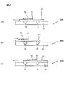
- FIGS. 7A to 7C are side views for explaining a first modified example of the operation of the container.
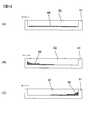
- FIGS. FIGS. 7A to 7H are side views for explaining a second modified example of the operation of the container.
- FIGS. FIGS. 9A to 9C are side views for explaining a third modification of the operation of the container.
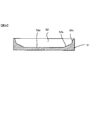
- FIGS. Sectional drawing which shows the 1st modification of a container accommodating part. Sectional drawing which shows the 2nd modification of a container accommodating part.
- FIG. 1 is a block diagram of an in-line plasma CVD (Chemical Vapor Deposition) apparatus showing an embodiment of the present invention.
- the plasma CVD apparatus 1 includes a load chamber 10, a heating chamber 20, and a film formation chamber 30.
- the load chamber 10 is a chamber for mounting the container 51 containing the object to be processed on the cart 41.
- the container 51 is formed with an accommodating portion 52 that opens from the upper surface in the thickness direction.
- the accommodating portion 52 has a flat bottom surface, and a small object to be processed such as a spherical shape, a cylindrical shape, or a polyhedron is accommodated in the accommodating portion 52.
- the load chamber 10 is provided with a transport mechanism 60A.
- the transport mechanism 60 ⁇ / b> A includes a large number of rollers 11.
- a cart 41 is mounted on the roller 11. Details of the transport mechanism will be described later.
- the heating chamber 20 is a chamber for preheating the object to be processed.
- the heating chamber 20 is provided with a lamp heater 22 and a transport mechanism 60B.
- the transport mechanism 60 ⁇ / b> B includes a large number of rollers 21.
- the workpiece is heated by a lamp heater.
- a vacuum pump 25 for exhausting the gas in the heating chamber 20 is provided via the gas valve 27 and piping.
- the film forming chamber 30 is a chamber for performing processing on the surface of the object to be processed.
- the film forming chamber 30 is provided with a transport mechanism 60C.
- the transport mechanism 60 ⁇ / b> C includes a large number of rollers 31.
- a cart 41 is mounted on the roller 31, and a sheathed heater 33 is provided on the lower surface of the cart 41 to heat the object to be processed contained in the container 51 via the cart 41.
- An electrode plate 34 is provided above the sheathed heater 33 and the roller 31.
- An RF power source 35 is connected to the electrode plate 34.
- a mass flow controller 36 and an introduction gas valve for adjusting the flow rate of the source gas supplied into the film forming chamber 30 are provided.
- An exhaust valve 39 and a vacuum pump 38 are provided for exhausting gas flowing through the mass flow controller 36 and the gas introduction valve 37 during film formation.
- FIG. 2 is a cross-sectional view of the region including the transport mechanism 60C and the sheathed heater 33 in the film forming chamber 30 of FIG. 1 taken along the line II-II.
- FIG. 3 shows the cart 41, the container 51, and the transport mechanism 60C. It is a perspective view. However, in FIG. 3, the base 61, the support mechanism, and the like are not shown for the convenience of the drawing.
- the transport mechanisms 60A and 60B have the same structure as the transport mechanism 60C.
- the roller 31 and the mechanism for driving the roller 31 are formed symmetrically on the left and right. Although only two pairs of each roller 31 are shown in FIG. 1, in practice, a large number of pairs are arranged with one pair on the left and right.
- FIG. 3 shows the cart 41, the container 51, and the transport mechanism 60C. It is a perspective view. However, in FIG. 3, the base 61, the support mechanism, and the like are not shown for the convenience of the drawing.
- the transport mechanisms 60A and 60B have the same structure
- Each roller 31 is rotatably supported on a base 61 (see FIG. 2) by a rotation shaft 77 thereof.
- a motor 62 is disposed outside the base 61, and a rotating shaft 63 of the motor 62 is coupled to a bevel gear 64.
- a bevel gear 72 meshes with the bevel gear 64. The shaft angle between the bevel gear 64 and the bevel gear 72 is 90 degrees.
- a shaft 71 is provided at the center of the bevel gear 72.
- Four bevel gears 73 are provided on the shaft 71.
- Each bevel gear 73 is disposed in a region corresponding to the rotation shaft 77 of the roller 31, and a bevel gear 74 that meshes with each bevel gear 73 is provided on the rotation shaft 77 of each roller 31.
- the shaft angle of the bevel gear 73 and the bevel gear 74 is 90 degrees.
- a cart 41 is mounted on the roller 31.
- the cart 41 is moved in the rotation direction of the roller 31 by driving the motor 62 and rotating the roller 31.
- a container 51 is fixed on the cart 41 by a fixing tool (not shown). Accordingly, the container 51 is moved integrally with the cart 41 by the roller 31.
- the transport mechanism 60C is configured as described above, and as shown in FIG. 3, when the rotating shaft 63 of the motor 62 rotates clockwise as indicated by the ⁇ mark, the bevel gear 64-the bevel gear 72-the shaft 71- The rotating shaft 77 of the roller 31 is rotated counterclockwise via the bevel gear 73-bevel gear 74, and the cart 41 mounted on the roller 31 is conveyed in the left direction.
- the rotation shaft 63 of the motor 62 is rotated counterclockwise, the rotation shaft 77 of the roller 31 is rotated clockwise through the same transmission path, and the cart 41 mounted on the roller 31 is conveyed to the right. .
- a sheathed heater 33 is provided between the left and right rollers 31 on the lower surface of the cart 41.
- the sheathed heater 33 has a structure in which a heating element 82 such as a nichrome wire is held in a metal case 81 and an inorganic insulating material is firmly filled therebetween.
- the sheathed heater 33 is disposed on the lower surface of the cart 41 so as to be close to the cart 41, and quickly heats the target object accommodated in the accommodating portion 52 of the container 51 via the cart 41 and the container 51. To do.
- the container 51 in which the object to be processed is accommodated in the accommodating portion 52 is attached to the cart 41 mounted on the roller 11 of the load chamber 10.
- the cart 41 to which the container 51 is attached may be disposed on the roller 11 so that the object to be processed is accommodated in the accommodating portion 52 of the container 51.
- the element for solar cells which has an n type diffused layer on the surface of spherical p-type silicon can be mentioned.
- the solar cell element is a spherical body having a diameter of about 0.5 to 1.0 mm. This illustration is not meant to limit the invention, but is intended to clarify.
- Opening the gate valve 2 and driving the motor to rotate the roller 11 conveys the cart 41 and the container 51 to the heating chamber 20.
- the gate valve 2 is closed, the heating chamber 20 is evacuated by the vacuum pump 25, and the object to be processed accommodated in the accommodating portion 52 of the container 51 is preheated by the lamp heater 22.
- the cart 51 and the container 51 containing the preheated object to be processed are conveyed to the film forming chamber 30.
- the gate valve 3 is closed, and the film forming chamber 30 is evacuated by the vacuum pump 38.
- the raw material is introduced into the film forming chamber 30 by adjusting the flow rate by the mass flow controller 36 while heating the object in the container 52 of the container 51 by the sheath heater 33. Further, power is supplied from the RF power source 35 to the electrode plate 34.
- the cart 41 is made of carbon or the like, plasma is generated using the electrode plate 34 as a cathode and the cart 41 as an anode.
- SiNx as a passivation film on the surface of a spherical solar cell element to be processed
- SiH 4 silane
- NH 3 ammonia
- N 2 nitrogen gas
- FIGS. 5A to 5C are side views showing the movement states of the cart 41 and the container 51 conveyed by the conveyance mechanism 60C.
- FIGS. 5A to 5C are respectively the same as FIG.
- FIG. 6 is a view for illustrating a rolling state of an object to be processed 55 accommodated in an accommodating portion 52 of a container 51 at positions corresponding to (C) to (C).
- FIG. 4A shows a state before the motor 62 rotates. In this state, the cart 41 and the container 51 are stationary, and the bottom surface of the container 52 of the container 51 is substantially flat. Therefore, the workpiece 55 accommodated in the container 52 of the container 51 is As shown in FIG. 4 (A), it is distributed almost uniformly over the entire bottom surface of the accommodating portion 52.
- the motor 62 is driven to rotate the rotating shaft 63 in the clockwise direction, and the roller is passed through the transmission path of the bevel gear 64 -the bevel gear 72 -the shaft 71 -the bevel gear 73 -the bevel gear 74. 31 is rotated counterclockwise.
- the container 51 is moved together with the cart 41 in the direction of the left arrow (left side) shown in the figure, and the state shown in FIG. 4B is obtained.
- the motor 62 is stopped at this position, as shown in FIG. 5B, the workpiece 55 accommodated in the accommodating portion 52 of the container 51 rotates the bottom surface of the accommodating portion 52 by the action of inertia force. It moves while contacting the inner wall on the left side of the accommodating portion 52.
- the rotating shaft 63 of the motor 62 is rotated counterclockwise, which is the reverse direction, and the roller 31 is rotated clockwise through the same transmission path as described above.
- the container 51 is moved together with the cart 41 in the direction of the ⁇ mark (right side) shown in the figure, and the state shown in FIG.
- the motor 62 is stopped at the timing when the cart 41 and the container 51 reach the position shown in FIG. 4 (C), as shown in FIG. 5 (C)
- the object to be processed accommodated in the accommodating portion 52 of the container 51. 55 moves while rotating the bottom surface of the housing portion 52 by the action of inertial force, and abuts on the right inner wall of the housing portion 52.
- the driving shown in FIGS. 4B to 4C is repeated, and during this time, the film formation on the object 55 is continued, so that a thin film is uniformly formed on the entire surface of each object 55. can do.
- the entire surface of the solar cell element is supplied by supplying SiH 4 (silane), NH 3 (ammonia), and N 2 (nitrogen gas) as source gases. Then, SiN x is formed in a uniform film thickness.
- the container 51 is reciprocated to form a thin film on the surface of the object to be processed 55 while rolling the bottom surface of the accommodating part 52 of the spherical object to be processed 55.
- the thin film formed on the entire surface can have a uniform thickness.
- the object to be processed 55 is accommodated in the accommodating part 52 having a substantially flat bottom surface, the object to be processed 55 is widely dispersed on the bottom surface of the accommodating part 52 and the rolling area is widened. Rolling is ensured, and the amount of objects to be processed that can be accommodated in the accommodating portion 52 can be increased. Note that other operations may be performed on the container 51 instead of the reciprocating operation. The modification is shown below.
- FIG. 6A to 6C are diagrams for explaining a method of swinging the container 51.
- FIG. The transport mechanism 60 has a support shaft 67 at the center of the base 61 that serves as the center of swinging of the base 61.
- FIG. 6A shows a state in which the base 61 is stationary in a direction substantially perpendicular to the gravity (horizontal direction). From this state, when the base 61 is rotated clockwise about the support shaft 67 as shown by the arrow ⁇ in the figure, the container 51 is tilted downward with the cart 41 as shown in FIG. 6B. To do. For this reason, the target object accommodated in the accommodating part 52 of the container 51 moves to the lower right side while the target object 55 rotates the bottom surface of the accommodating part 52.
- the container 51 is moved upward together with the cart 41 as shown in FIG. 6C. Tilt. For this reason, the object to be processed accommodated in the accommodating part 52 of the container 51 moves downward on the left side while the object to be processed 55 rotates the bottom surface of the accommodating part 52.
- a thin film is formed on the surface of the object to be processed.
- a thin film having a uniform thickness can also be formed on the surface of the object to be processed by swinging the container in which the object to be processed is accommodated.
- an appropriate driving mechanism such as connecting a rod of a reciprocating cylinder or an eccentric cam rotated by a motor to the end of the base 61 is adopted. Can do.
- FIGS. 7A to 7H are views for explaining a method for causing a container to perform a combined operation of a reciprocating operation and a swinging operation.
- FIG. 7A shows a state where the base 61 is stationary in a state (horizontal state) perpendicular to gravity. In this state, the motor 62 is driven and the roller 31 is rotated to move the cart 41 and the container 51 in the left direction as indicated by ⁇ , and the base 61 is supported by the support shaft 67 as indicated by ⁇ .
- FIG. 7B the container 51 is slightly lowered to the right.
- the motor 62 is driven in the reverse direction, the roller 31 is rotated, and the cart 41 and the container 51 are moved in the left direction as indicated by ⁇ and as indicated by ⁇ .
- the container 51 is slightly lowered to the right as shown in FIG.
- the motor 62 is driven in the same direction and the roller 31 is rotated to move the cart 41 and the container 51 further to the left as indicated by ⁇ and as indicated by ⁇ .
- the container 51 becomes horizontal as shown in FIG.
- the driving shown in FIGS. 7A to 7H is repeatedly performed, and during this time, the film formation on the target object 55 is continued to form a thin film uniformly on the entire surface of each target object 55. can do.
- the container 51 is reciprocated in the horizontal direction and is swung in the direction in which the gravity acts, so that the object to be processed accommodated in the container 52 of the container 51 is Horizontal inertial force and gravity act. For this reason, it is possible to further ensure the rolling of the object to be processed.
- (Variation 3 of container operation) 8A to 8C show examples in which the inertial force acting on the object to be processed can be further increased.
- stoppers 68 are provided at both ends of the base 61. The distance between the stoppers 68 is larger than the length of the cart 41, and the cart 41 can reciprocate between the stoppers 68. Moreover, the outer side surface of the both sides of the container 51 is contact
- FIG. 8A shows a state where the motor 62 is not driven and is stopped. From this state, the motor 62 is driven, and the cart 31 and the container 51 are moved in the leftward direction indicated by ⁇ in FIG. If the motor 62 is continuously driven, the left end of the cart 41 collides with the left stopper 68 as shown in FIG. 8B. Due to the impact caused by the collision, the object to be processed accommodated in the accommodating portion 52 of the container 51 rolls reliably.
- the cart 41 is caused to collide with the stopper 68, and the workpiece 55 accommodated in the accommodation portion 52 of the container 51 is rolled by the impact force at that time, and the cart 41 collides with the stopper 68. Since the impact at that time is larger than when the motor 62 is suddenly stopped, the rolling of the object to be processed in the accommodating portion 52 is ensured. Further, the impact force can be set to an arbitrary magnitude by adjusting the conveyance speed of the container 51.
- FIG. 9 shows a cross-sectional view of a modified example of the accommodating portion 52 of the container 51.
- gentle inclined portions 52 b are formed on both side edges of the bottom surface 52 a of the accommodating portion 52.
- a steep slope 52c is formed following the gentle slope 52b.
- the gentle inclined portion 52b prevents a minute object to be processed from being caught in a vertical corner portion that is a boundary portion between the bottom surface and the side surface, thereby restricting rolling. Further, the steep inclined portion 52c prevents the object to be processed from jumping out of the accommodating portion 52 from the gentle inclined portion 52b.
- FIG. 10 shows a cross-sectional view of another modified example of the container 51.
- the bottom surface 52d of the accommodating portion 52 has an arc shape.
- the side surface of the accommodating portion 52 is a straight steeply inclined surface 52e with R at the end.
- an overhang portion 52f is formed on the upper portion of the steeply inclined surface 52e. The overhang portion 52 f prevents the object to be processed from jumping out of the storage portion 52. Moreover, the overhang portion 52 f still drops the object to be processed that has jumped out of the storage portion 52 into the storage portion 52 again.
- the roughness of the bottom surface of the container 52 also affects the rolling operation of the object to be processed.
- the bottom surface of the accommodating portion 52 may be a mirror surface.
- fine irregularities may be formed on the bottom surface of the housing portion 52.
- the object to be processed is a polyhedron
- the bottom surface of the accommodating part 52 is a mirror surface, one surface of the object to be processed slides on the bottom surface of the accommodating part 52 and is difficult to roll. In such a case, it is recommended to form fine irregularities on the bottom surface of the accommodating portion 52.
- the fine unevenness formed on the bottom surface of the accommodating portion 52 is too deep or the pitch of the unevenness is larger than each surface size of the polyhedron, the polyhedron will be retained in the recess. .
- the reciprocating operation and the swinging operation is performed on the container 51, so that the object 55 is moved on the surface of the object 55 while rolling the bottom surface of the container 52. Since the thin film is formed, the thin film formed on the entire surface of the object 55 can be made to have a uniform thickness. Further, since the object to be processed 55 is accommodated in the accommodating part 52 having a substantially flat bottom surface, the object to be processed 55 is widely dispersed on the bottom surface of the accommodating part 52, and the rolling area is widened. The moving operation can be further ensured, and the amount of the object to be processed that can be accommodated in the accommodating portion 52 can be increased to improve the productivity.
- the case where a thin film is formed on the object to be processed has been described as an example.
- the object to be processed is diffused or irradiated with an ion beam or the like to cause physical or chemical changes.
- the present invention can be applied to various types of processing including the case where the process is performed.
- the apparatus for processing the object to be processed is not limited to the plasma CVD apparatus but can be applied to other apparatuses such as a sputtering apparatus.
- the container may be moved in a two-dimensional manner instead of a one-dimensional manner, such as by swinging the container in the horizontal state.
- the operation of the container may be a combination of these operations and the swinging operation in the direction of gravity.
- the processing object 55 has been described in the embodiment in which the processing object 55 is accommodated in a container 51 different from the cart 41. It can also be set as the form to do.
- the surface treatment apparatus of the present invention can be variously modified and configured.
- the surface treatment apparatus has a container that accommodates the object to be treated, and a space that accommodates the container.
- a surface processing unit having a processing chamber into which a gas for processing is introduced, and a container driving mechanism for causing a container in which an object to be processed is accommodated to reciprocate or swing. If it is.
- the present invention provides an accommodating process for accommodating a container in which an object to be treated is accommodated, and the object to be processed while rolling the object to be processed in the container by causing the container to reciprocate or swing.
- the present invention is applied to any of the surface treatment methods including a treatment process for treating the surface of the body.
Landscapes
- Chemical & Material Sciences (AREA)
- General Chemical & Material Sciences (AREA)
- Chemical Kinetics & Catalysis (AREA)
- Engineering & Computer Science (AREA)
- Materials Engineering (AREA)
- Mechanical Engineering (AREA)
- Metallurgy (AREA)
- Organic Chemistry (AREA)
- Chemical Vapour Deposition (AREA)
- Physical Vapour Deposition (AREA)
- Formation Of Insulating Films (AREA)
Abstract
Description
しかしながら、被処理体が球状の場合、特に、微小な部材である場合には、被処理体は、六角筒型バレルの回転に追随して上昇する作用が小さくなり、上昇する高さが極めて小さくなってしまう。つまり、被処理体は、六角筒型バレルの最も低い箇所の直ぐ近傍に、ほぼ直線状の厚い層状に集合し、殆ど攪拌作用が行われない状態となる。このため、被処理体に均一な厚さに成膜をすることが困難であった。
本発明の第2の態様による表面処理装置は、第1の態様における表面処理装置において、表面処理ユニットは、容器と対向する面が平坦な電極板を含み、容器駆動機構は、容器を、電極板にほぼ平行な面内において、容器に収容される被処理体を転動させるように構成されている。
本発明の第3の態様による表面処理装置は、第1の態様または第2の態様のいずれかの態様における表面処理装置において、表面処理ユニットは、容器と対向する面が平坦な電極板を含み、容器駆動機構は、容器を、電極板に垂直な方向に揺動動作させるように構成されている。
本発明の第4の態様による表面処理装置は、第1乃至第3の態様のいずれかの態様における表面処理装置において、容器駆動機構は、少なくとも一対のローラと、ローラを駆動する駆動ユニットを有する。
本発明の第5の態様による表面処理装置は、第1乃至第4の態様のいずれかの態様における表面処理装置において、容器駆動機構は、容器の移動を停止させるストッパを含む。
本発明の第6の態様による表面処理装置は、第1乃至第5の態様のいずれかの態様における表面処理装置において、表面処理ユニットは、球状、柱状または多面体の被処理体の表面に薄膜を成膜するためのプラズマ発生ユニットを有する。
本発明の第8の態様による表面処理方法は、第7の態様の表面処理方法において、重力に対してほぼ垂直な面内において、容器を往復動作あるいは揺動動作の少なくとも一方の動作をさせる。
本発明の第9の態様による表面処理方法は、第7の態様または第8の態様における表面処理方法において、容器を、重力方向に揺動動作させる。
図1は、本発明の一実施形態を示すインライン式プラズマCVD(Chemical Vapor Deposition)装置のブロック図ある。プラズマCVD装置1は、ロード室10、加熱室20、成膜室30を備えている。
シーズヒータ33およびローラ31の上方には、電極板34が設けられている。電極板34にはRF電源35が接続されている。また、成膜室30内に供給される原料ガスの流量を調整するマスフローコントローラ36および導入ガスバルブが設けられている。成膜時にマスフローコントローラ36およびガス導入バルブ37を通して流れるガスを排気するための排気バルブ39及び真空ポンプ38が設けられている。
搬送機構60Cは、ローラ31およびローラ31を駆動する機構が左右に対称に形成されている。
各ローラ31は、図1では、二対のみが図示されているが、実際には、左右の1個ずつを一対として多数対が配置されている。図3では四対が図示されているが、これは一例であって、適宜の数量とすることができる。各ローラ31は、その回転軸77が基台61(図2参照)に回転可能に支持されている。基台61の外側にはモータ62が配置されており、モータ62の回転軸63は、傘歯車64に結合されている。傘歯車64には、傘歯車72が噛合っている。傘歯車64と傘歯車72との軸角は90度である。
先ず、ロード室10のローラ11上に搭載されたカート41に、収容部52内に被処理体が収容された容器51を取り付ける。容器51が取り付けられたカート41をローラ11上に配置して、容器51の収容部52内に被処理体を収容するようにしてもよい。
被処理体の一例として、球状のp型シリコンの表面にn型拡散層を有する太陽電池用素子を挙げることができる。太陽電池用素子は、直径が0.5~1.0mm程度の球状体である。この例示は、本発明を限定する意味ではなく、理解を明確にすることを目的とするものである。
図4(A)は、モータ62が回転する前の状態を示す。この状態では、カート41および容器51は静止しており、容器51の収容部52の底面はほぼ平坦とされているので、容器51の収容部52内に収容された被処理体55は、図4(A)に図示されるように、収容部52の底面の全面にほぼ一様に分散している。
なお、容器51に対しては往復動作に変えて他の動作をさせてもよい。以下にその変形例を示す。
図6(A)~(C)は、容器51を揺動動作させる方法を説明するための図である。
搬送機構60は、基台61の中心に、基台61の揺動の中心となる支軸67を有する。図6(A)は、基台61が重力に対してほぼ垂直な方向(水平方向)に静止している状態を示す。この状態から、図示の↑印の如く、基台61を支軸67を中心に時計方向に回転すると、図6(B)に図示されているように、カート41と共に容器51が右下がりに傾斜する。このため、容器51の収容部52内に収容された被処理体は、被処理体55が収容部52の底面を回転しながら、右側下方に移動する。
このようの被処理体が収容された容器を揺動動作させることによっても、被処理体の表面に均一な厚さの薄膜を形成することができる。
なお、基台61を駆動する構造として、基台61の端部に、往復動作するシリンダのロッドを連結する、またはモータにより回転される偏心カムを連結する等、適宜な駆動機構を採用することができる。
図7(A)~(H)は、容器に、往復動作と揺動動作の複合的な動作をさせる方法を説明するための図である。
図7(A)は、基台61を、重力に対して、垂直な状態(水平状態)に静止している状態を示す。
この状態で、モータ62を駆動し、ローラ31を回転させて、←印に示すようにカート41と容器51を左側方向に移動させると共に、↑印に示すように基台61を、支軸67を中心に時計方向に回転させると、図7(B)に図示するように容器51は少し右下がりの状態となる。
図7(D)の状態から、さらに、モータ62を同方向に駆動し、ローラ31を回転させて、→印に示すようにカート41と容器51をさらに右側方向に移動させると共に、↓印に示すように基台61を、支軸67を中心にさらに反時計方向に回転させると、図7(E)に図示するように、カート41と容器51は水平状態となる。
図7(F)の状態から、さらに、モータ62を同方向に駆動し、ローラ31を回転させて、→印に示すようにカート41と容器51をさらに右側方向に移動させると共に、↓印に示すように基台61を、支軸67を中心にさらに反時計方向に回転させると、図7(G)に図示するように容器51はさらに右上がりの状態となる。
図7(H)の状態から、モータ62を同方向に駆動し、ローラ31を回転させて、←印に示すようにカート41と容器51をさらに左側方向に移動させると共に、↑印に示すように基台61を、支軸67を中心にさらに時計方向に回転させると、図7(A)に図示するように容器51は水平状態となる。
この容器動作の変形例2では、容器51を水平方向に往復動作させながら、且つ、重力の作用する方向に揺動動作させるので、容器51の収容部52内に収容された被処理体には、水平方向の慣性力と重力とが作用する。このため、被処理体の転動をさらに確実にすることができる。
図8(A)~(C)は、被処理体に作用する慣性力を一層大きくすることができる例を示す。
この実施例の搬送機構60には、基台61の両端にストッパ68が設けられている。ストッパ68の間隔は、カート41の長さより大きくされ、ストッパ68間でカート41が往復動作可能な長さとなっている。また、容器51の両側の外側面は、カート41に植立されたストップピン56に当接され、長さ方向への移動が規制されている。
(収容部形状の変形例1)
図9は、容器51の収容部52の変形例の断面図を示す。この変形例では、収容部52の底面52aの両側縁に緩やかな傾斜部52bが形成されている。また、緩やかな傾斜部52bに引き続いて急な傾斜部52cが形成されている。緩やかな傾斜部52bは、微小な被処理体が底面と側面との境界部である垂直な角部に挟まって、転動が規制されるのを防止する。また、急な傾斜部52cは、被処理体が緩やかな傾斜部52bから、収容部52の外部に飛び出すのを防止する。
図10は、容器51の別の変形例の断面図を示す。この変形例においては、収容部52の底面52dが円弧状となっている。収容部52の側面は、端部にRがついた直線状の急傾斜面52eとなっている。また、急傾斜面52eの上部には、オーバーハング部52fが形成されている。オーバーハング部52fは、被処理体が収容部52から飛び出すのを防止する。また、オーバーハング部52fは、それでも、収容部52から飛び出した被処理体を、再び、収容部52内に落下させる。
日本国特許出願2010年第175176号(2010年8月4日出願)
Claims (9)
- 被処理体が収容される容器と、
前記容器を収容する空間を有し、前記被処理体の表面を処理するためのガスが導入される処理室を有する表面処理ユニットと、
被処理体が収容される前記容器を、往復動作または揺動動作の少なくとも一つの動作をさせる容器駆動機構と
を具備する表面処理装置。 - 請求項1に記載の表面処理装置において、前記表面処理ユニットは、前記容器と対向する面が平坦な電極板を含み、前記容器駆動機構は、前記容器を、前記電極板にほぼ平行な面内において、前記容器に収容される被処理体を転動させる。
- 請求項1または2のいずれか1項に記載の表面処理装置において、前記表面処理ユニットは、前記容器と対向する面が平坦な電極板を含み、前記容器駆動機構は、前記容器を、前記電極板に垂直な方向に揺動動作させる。
- 請求項1乃至3のいずれか1項に記載の表面処理装置において、前記容器駆動機構は、少なくとも一対のローラと、前記ローラを駆動する駆動ユニットを有する。
- 請求項1乃至4のいずれか1項に記載の表面処理装置において、前記容器駆動機構は、前記容器の移動を停止させるストッパを含む。
- 請求項1乃至5のいずれか1項に記載の表面処理装置において、前記表面処理ユニットは、球状、柱状または多面体の被処理体の表面に薄膜を成膜するためのプラズマ発生ユニットを有する。
- 被処理体が収容される容器を収容する収容工程と、
前記容器を往復動作あるいは揺動動作の少なくとも一方の動作をさせて前記被処理体を前記容器内で転動させながら前記被処理体の表面に処理を施す処理工程とを備える表面処理方法。 - 請求項7に記載の表面処理方法において、重力に対してほぼ垂直な面内において、前記容器を往復動作あるいは揺動動作の少なくとも一方の動作をさせる。
- 請求項7または8に記載の表面処理方法において、前記容器を、重力方向に揺動動作させる。
Priority Applications (2)
| Application Number | Priority Date | Filing Date | Title |
|---|---|---|---|
| JP2012527764A JP5811092B2 (ja) | 2010-08-04 | 2011-08-04 | 表面処理装置および表面処理方法 |
| CN2011800375859A CN103052734A (zh) | 2010-08-04 | 2011-08-04 | 表面处理装置和表面处理方法 |
Applications Claiming Priority (2)
| Application Number | Priority Date | Filing Date | Title |
|---|---|---|---|
| JP2010-175176 | 2010-08-04 | ||
| JP2010175176 | 2010-08-04 |
Publications (1)
| Publication Number | Publication Date |
|---|---|
| WO2012018075A1 true WO2012018075A1 (ja) | 2012-02-09 |
Family
ID=45559571
Family Applications (1)
| Application Number | Title | Priority Date | Filing Date |
|---|---|---|---|
| PCT/JP2011/067854 Ceased WO2012018075A1 (ja) | 2010-08-04 | 2011-08-04 | 表面処理装置および表面処理方法 |
Country Status (3)
| Country | Link |
|---|---|
| JP (1) | JP5811092B2 (ja) |
| CN (1) | CN103052734A (ja) |
| WO (1) | WO2012018075A1 (ja) |
Cited By (3)
| Publication number | Priority date | Publication date | Assignee | Title |
|---|---|---|---|---|
| US20150211110A1 (en) * | 2012-09-21 | 2015-07-30 | Technische Universitat Wien | Device for coating a substrate made of particles |
| JP2016122750A (ja) * | 2014-12-25 | 2016-07-07 | 株式会社島津製作所 | ワークホルダ及び成膜装置 |
| WO2021060160A1 (ja) * | 2019-09-25 | 2021-04-01 | 芝浦機械株式会社 | 表面処理装置 |
Citations (6)
| Publication number | Priority date | Publication date | Assignee | Title |
|---|---|---|---|---|
| JPH0340953A (ja) * | 1989-07-06 | 1991-02-21 | Tomoegawa Paper Co Ltd | 超伝導体成形物の製造方法 |
| JPH05311408A (ja) * | 1992-05-06 | 1993-11-22 | Kobe Steel Ltd | 球体用のインライン式アークイオンプレーティング装置 |
| JPH09228027A (ja) * | 1996-02-23 | 1997-09-02 | Ntn Corp | 硬質カーボン膜の球体被覆方法 |
| JP2007204786A (ja) * | 2006-01-31 | 2007-08-16 | Bridgestone Corp | 粒子コーティング方法及び粒子コーティング装置 |
| JP2008231502A (ja) * | 2007-03-20 | 2008-10-02 | Ulvac Japan Ltd | 粉体攪拌機構、金属微粒子担持粉体の作製方法及び燃料電池用触媒 |
| JP2010111920A (ja) * | 2008-11-06 | 2010-05-20 | Ntn Corp | 球状体の表面処理用治具、球状体の表面処理方法および球状部品の製造方法 |
Family Cites Families (4)
| Publication number | Priority date | Publication date | Assignee | Title |
|---|---|---|---|---|
| JP3409408B2 (ja) * | 1993-12-27 | 2003-05-26 | 日新電機株式会社 | イオン注入装置 |
| US5670218A (en) * | 1995-10-04 | 1997-09-23 | Hyundai Electronics Industries Co., Ltd. | Method for forming ferroelectric thin film and apparatus therefor |
| JP3904658B2 (ja) * | 1997-03-27 | 2007-04-11 | 正路 朝本 | 半面被覆粒状体の製造装置 |
| JP2006342384A (ja) * | 2005-06-08 | 2006-12-21 | Moritex Corp | 全面フィルタ膜付き球レンズの製造方法,製造装置及び全面フィルタ膜付き球レンズ並びに光モジュール |
-
2011
- 2011-08-04 CN CN2011800375859A patent/CN103052734A/zh active Pending
- 2011-08-04 WO PCT/JP2011/067854 patent/WO2012018075A1/ja not_active Ceased
- 2011-08-04 JP JP2012527764A patent/JP5811092B2/ja not_active Expired - Fee Related
Patent Citations (6)
| Publication number | Priority date | Publication date | Assignee | Title |
|---|---|---|---|---|
| JPH0340953A (ja) * | 1989-07-06 | 1991-02-21 | Tomoegawa Paper Co Ltd | 超伝導体成形物の製造方法 |
| JPH05311408A (ja) * | 1992-05-06 | 1993-11-22 | Kobe Steel Ltd | 球体用のインライン式アークイオンプレーティング装置 |
| JPH09228027A (ja) * | 1996-02-23 | 1997-09-02 | Ntn Corp | 硬質カーボン膜の球体被覆方法 |
| JP2007204786A (ja) * | 2006-01-31 | 2007-08-16 | Bridgestone Corp | 粒子コーティング方法及び粒子コーティング装置 |
| JP2008231502A (ja) * | 2007-03-20 | 2008-10-02 | Ulvac Japan Ltd | 粉体攪拌機構、金属微粒子担持粉体の作製方法及び燃料電池用触媒 |
| JP2010111920A (ja) * | 2008-11-06 | 2010-05-20 | Ntn Corp | 球状体の表面処理用治具、球状体の表面処理方法および球状部品の製造方法 |
Cited By (8)
| Publication number | Priority date | Publication date | Assignee | Title |
|---|---|---|---|---|
| US20150211110A1 (en) * | 2012-09-21 | 2015-07-30 | Technische Universitat Wien | Device for coating a substrate made of particles |
| JP2016122750A (ja) * | 2014-12-25 | 2016-07-07 | 株式会社島津製作所 | ワークホルダ及び成膜装置 |
| WO2021060160A1 (ja) * | 2019-09-25 | 2021-04-01 | 芝浦機械株式会社 | 表面処理装置 |
| CN114450082A (zh) * | 2019-09-25 | 2022-05-06 | 芝浦机械株式会社 | 表面处理装置 |
| TWI779356B (zh) * | 2019-09-25 | 2022-10-01 | 日商芝浦機械股份有限公司 | 表面處理裝置 |
| JP7553456B2 (ja) | 2019-09-25 | 2024-09-18 | 芝浦機械株式会社 | 表面処理装置 |
| CN114450082B (zh) * | 2019-09-25 | 2025-03-25 | 芝浦机械株式会社 | 表面处理装置 |
| US12522912B2 (en) | 2019-09-25 | 2026-01-13 | Shibaura Machine Co., Ltd. | Surface treatment device |
Also Published As
| Publication number | Publication date |
|---|---|
| JPWO2012018075A1 (ja) | 2013-10-03 |
| CN103052734A (zh) | 2013-04-17 |
| JP5811092B2 (ja) | 2015-11-11 |
Similar Documents
| Publication | Publication Date | Title |
|---|---|---|
| JP7835531B2 (ja) | 基材を処理するための基材処理装置および方法 | |
| US9570307B2 (en) | Methods of doping substrates with ALD | |
| JP5811092B2 (ja) | 表面処理装置および表面処理方法 | |
| KR101561741B1 (ko) | 열처리 장치 및 열처리 방법 | |
| KR20210105439A (ko) | 금속-프리 리간드들을 사용하는 금속 원자 층 에칭 및 증착 장치들과 프로세스들 | |
| WO2013161768A1 (ja) | 成膜方法、成膜装置、及び、成膜システム | |
| KR20060135937A (ko) | 이온 빔을 통해 공작물을 왕복 운동하는 방법 | |
| KR101289504B1 (ko) | 이온 빔을 통해 공작물을 주사하는 왕복 구동 장치 | |
| TWI238470B (en) | Film coating unit and film coating method | |
| CN104769151B (zh) | 成膜装置 | |
| CN206654950U (zh) | 用于涂布基板的溅射沉积装置 | |
| US7682954B2 (en) | Method of impurity introduction, impurity introduction apparatus and semiconductor device produced with use of the method | |
| TW201945567A (zh) | 用環境控制進行線性掃描的物理氣相沉積方法和裝置 | |
| JP2017522455A (ja) | 層を堆積する方法、トランジスタを製造する方法、電子デバイスのための層スタック、及び電子デバイス | |
| JP2005213616A (ja) | 蒸着方法および装置ならびにプラズマディスプレイパネルの製造方法 | |
| TWI473904B (zh) | 用於使化學液與基板表面均勻反應之方法及其設備 | |
| JP2006060159A (ja) | ビーム照射方法およびビーム照射装置 | |
| KR101089626B1 (ko) | 기판 이송이 에어 베어링을 통해 이루어지는 레이저 열처리 장치 | |
| KR101200358B1 (ko) | 증착용 파우더 공급장치 및 이를 구비하는 박막 증착 장치 | |
| KR20220074291A (ko) | 시소운동이 적용된 기판장착장치 | |
| JP7802603B2 (ja) | エッチング装置 | |
| JP2014015633A (ja) | 成膜装置、及び成膜装置用搬送トレイ | |
| KR20170106321A (ko) | 성막 장치, 코팅막 부착 절삭 공구의 제조 방법 | |
| KR102169017B1 (ko) | 스퍼터링 장치 및 스퍼터링 방법 | |
| JP2014014816A (ja) | 基板処理方法及び基板処理装置 |
Legal Events
| Date | Code | Title | Description |
|---|---|---|---|
| WWE | Wipo information: entry into national phase |
Ref document number: 201180037585.9 Country of ref document: CN |
|
| 121 | Ep: the epo has been informed by wipo that ep was designated in this application |
Ref document number: 11814700 Country of ref document: EP Kind code of ref document: A1 |
|
| WWE | Wipo information: entry into national phase |
Ref document number: 2012527764 Country of ref document: JP |
|
| NENP | Non-entry into the national phase |
Ref country code: DE |
|
| 122 | Ep: pct application non-entry in european phase |
Ref document number: 11814700 Country of ref document: EP Kind code of ref document: A1 |