WO2012017993A1 - 赤外線送受信システム及び赤外線送受信方法 - Google Patents
赤外線送受信システム及び赤外線送受信方法 Download PDFInfo
- Publication number
- WO2012017993A1 WO2012017993A1 PCT/JP2011/067615 JP2011067615W WO2012017993A1 WO 2012017993 A1 WO2012017993 A1 WO 2012017993A1 JP 2011067615 W JP2011067615 W JP 2011067615W WO 2012017993 A1 WO2012017993 A1 WO 2012017993A1
- Authority
- WO
- WIPO (PCT)
- Prior art keywords
- infrared
- terminal
- data
- infrared transmission
- reception
- Prior art date
- Legal status (The legal status is an assumption and is not a legal conclusion. Google has not performed a legal analysis and makes no representation as to the accuracy of the status listed.)
- Ceased
Links
Images









Classifications
-
- G—PHYSICS
- G01—MEASURING; TESTING
- G01S—RADIO DIRECTION-FINDING; RADIO NAVIGATION; DETERMINING DISTANCE OR VELOCITY BY USE OF RADIO WAVES; LOCATING OR PRESENCE-DETECTING BY USE OF THE REFLECTION OR RERADIATION OF RADIO WAVES; ANALOGOUS ARRANGEMENTS USING OTHER WAVES
- G01S5/00—Position-fixing by co-ordinating two or more direction or position line determinations; Position-fixing by co-ordinating two or more distance determinations
- G01S5/16—Position-fixing by co-ordinating two or more direction or position line determinations; Position-fixing by co-ordinating two or more distance determinations using electromagnetic waves other than radio waves
-
- G—PHYSICS
- G01—MEASURING; TESTING
- G01S—RADIO DIRECTION-FINDING; RADIO NAVIGATION; DETERMINING DISTANCE OR VELOCITY BY USE OF RADIO WAVES; LOCATING OR PRESENCE-DETECTING BY USE OF THE REFLECTION OR RERADIATION OF RADIO WAVES; ANALOGOUS ARRANGEMENTS USING OTHER WAVES
- G01S1/00—Beacons or beacon systems transmitting signals having a characteristic or characteristics capable of being detected by non-directional receivers and defining directions, positions, or position lines fixed relatively to the beacon transmitters; Receivers co-operating therewith
- G01S1/70—Beacons or beacon systems transmitting signals having a characteristic or characteristics capable of being detected by non-directional receivers and defining directions, positions, or position lines fixed relatively to the beacon transmitters; Receivers co-operating therewith using electromagnetic waves other than radio waves
- G01S1/703—Details
- G01S1/7032—Transmitters
- G01S1/7034—Mounting or deployment thereof
-
- H—ELECTRICITY
- H04—ELECTRIC COMMUNICATION TECHNIQUE
- H04B—TRANSMISSION
- H04B10/00—Transmission systems employing electromagnetic waves other than radio-waves, e.g. infrared, visible or ultraviolet light, or employing corpuscular radiation, e.g. quantum communication
- H04B10/11—Arrangements specific to free-space transmission, i.e. transmission through air or vacuum
- H04B10/114—Indoor or close-range type systems
- H04B10/1149—Arrangements for indoor wireless networking of information
-
- G—PHYSICS
- G01—MEASURING; TESTING
- G01S—RADIO DIRECTION-FINDING; RADIO NAVIGATION; DETERMINING DISTANCE OR VELOCITY BY USE OF RADIO WAVES; LOCATING OR PRESENCE-DETECTING BY USE OF THE REFLECTION OR RERADIATION OF RADIO WAVES; ANALOGOUS ARRANGEMENTS USING OTHER WAVES
- G01S2201/00—Indexing scheme relating to beacons or beacon systems transmitting signals capable of being detected by non-directional receivers and defining directions, positions, or position lines fixed relatively to the beacon transmitters
- G01S2201/01—Indexing scheme relating to beacons or beacon systems transmitting signals capable of being detected by non-directional receivers and defining directions, positions, or position lines fixed relatively to the beacon transmitters adapted for specific applications or environments
Definitions
- the present invention relates to an infrared transmission / reception system including an infrared transmitter for transmitting infrared rays and a terminal for receiving infrared rays, and more particularly to a technique for controlling the infrared transmission interval of the infrared transmitter and the infrared reception interval of the terminal.
- face-to-face communication at least two or more people involved in the communication generate a conversation rhythm and place atmosphere in real time. For this reason, in face-to-face communication, emotion resonance and idea creation may occur from places that cannot be predicted.
- Work style is a pattern of how each person works, such as when, where, and what each person does.
- the work style reflects the content of the business as an external factor and the personality as an internal factor.
- the conventional technology for visualizing the business process that analyzes the work itself does not take into account the effect of matters that are not directly reflected in the work product.
- the matters that are not directly reflected in the work product are, for example, reading, walking, chatting, and the like.
- a new idea is said to be a new combination of existing ideas (elements). For this reason, a person who specializes in a different field brings a new viewpoint to a certain field, and a novel idea may be created.
- context such as the situation in which communication is performed is important. For example, when it is detected that five people have met in a certain time zone, it is important to identify whether it is a chat near the person's seat or a meeting surrounding the table.
- Japanese Patent Application Laid-Open No. 2008-102023 discloses a technique for analyzing a personal work style by specifying a personal position.
- Japanese Patent Application Laid-Open No. 2008-102023 describes specifying an individual's position using an infrared transmitter that transmits infrared rays and a terminal that can receive infrared rays. Specifically, the position of the terminal that has received the infrared light is specified by sequentially transmitting infrared light including different IDs for each of the plurality of infrared transmission units provided in the infrared transmitter.
- Japanese Patent Laid-Open No. 2008-301071 discloses a terminal including an infrared transmitter and an infrared receiver that transmit and receive infrared between terminals in order to detect that each terminal has faced.
- Japanese Patent Application Laid-Open No. 2008-301071 describes that the infrared receiving unit sequentially becomes in a state where reception is possible in order to reduce the power consumption of the terminal.
- Japanese Patent Application Laid-Open No. 2008-102023 discloses an arrangement of an infrared transmitter so that an infrared irradiation range covers a position detection range of a moving body.
- this infrared transmitter is premised on the upper part of the space where the moving body exists, it accurately grasps the position of the terminal existing in an arbitrary angle direction with respect to the infrared transmitter. It is not possible. Moreover, it does not describe about the time (infrared transmission time) for all the infrared transmission units provided in the infrared transmitter to transmit infrared rays once.
- Japanese Patent Laid-Open No. 2008-301071 discloses that four infrared transmissions are made at different timings. However, it relates to infrared transmission / reception between terminals, and is intended for face-to-face detection of each terminal. Therefore, the position of the terminal that exists in a certain space is not detected by using the infrared transmission device arranged in that space, but the position of the terminal that exists in an arbitrary angle direction with respect to the infrared transmission device is accurately grasped. I can't do it.
- An object of the present invention is to provide an infrared transmission / reception system capable of ensuring that a terminal receives infrared rays from an infrared transmission unit provided in an infrared transmitter and accurately grasping the position of the terminal existing in an arbitrary angle direction. .
- a typical example of the invention disclosed in the present application is as follows. That is, in an infrared transmission / reception system comprising: at least one infrared transmission device that transmits infrared data by infrared rays; and at least one terminal that receives infrared data transmitted by the infrared transmission device, the infrared transmission device is a predetermined one.
- a plurality of infrared transmission units that transmit the infrared data in a range of are arranged in a plurality of directions, each of the infrared transmission units transmits infrared data once in a predetermined first time, and the infrared of each of the infrared transmission units
- the terminal repeatedly transmits the infrared data so that the data transmission timing does not overlap
- the terminal includes a microcontroller that executes arithmetic processing, a data storage unit that can store data, and at least one infrared receiver.
- each infrared receiver is once in a second time longer than the first time.
- a ready to receive an outside line data the reception timing of the infrared data of the infrared receiver is so as not to overlap, characterized by receiving repeatedly the infrared data.
- an infrared transmission / reception system capable of ensuring that the terminal receives infrared rays from the infrared transmission unit provided in the infrared transmitter and accurately grasping the position of the terminal.
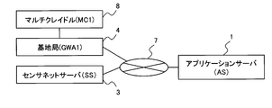
- FIG. 1 is an explanatory diagram of the configuration of the terminal location specifying system according to the first embodiment of this invention.
- the terminal location specifying system includes an application server (AS) 1, a client A (CLA) 2A, a client B (CLB) 2B (hereinafter, clients A and B are collectively referred to as a client 2), a sensor network server (SS) 3, a base Station A (GWA) 4A, base station B (GWB) 4B, base station C (GWC) 4C (hereinafter, base stations 4 are collectively referred to as base station 4), terminal (TR) 5, and red An external transmitter (IRT) 6 is provided.
- AS application server
- CLA client A
- CLB client B
- SS sensor network server
- GWA base Station A
- GWB base station B
- GWC base station C
- TR terminal
- IRT red
- IRT an external transmitter
- Application server 1, client 2, sensor network server 3, and base station 4 are connected via a network (NW) 7.
- NW network
- the infrared transmitter 6 transmits infrared data in multiple directions.
- the terminal 5 When the terminal 5 is worn by a person and is positioned in the direction in which the infrared data is transmitted by the infrared transmitter 6, the terminal 5 receives the infrared data transmitted in the direction.
- the base station 4 collects a reception result (sensing data) that is a result of the terminal 5 receiving the infrared data by transmitting a control command to the terminal 5. Note that the base station 4 may collect the sensing data by transmitting the sensing data at a predetermined cycle without the base station 4 transmitting the control command.
- the sensor network server 3 collects sensing data from the base station 4 via the network 7.
- the application server 1 collects sensing data from the sensor network server 3 via the network 7, identifies the position of the terminal 5 based on the collected sensing data, and generates organization communication data indicating the position of the identified terminal 5, etc. Then, the generated organization communication data is transmitted to the client 2 via the network 7.
- the client 2 is operated by the user, causes the application server 1 to generate organization communication data, and presents the organization communication data transmitted by the application server 1 to the user.
- FIG. 1 illustrates that the terminal location specifying system includes a plurality of clients 2 and base stations 4, it is sufficient that at least one client 2 and base station 4 are provided.
- the sensor network server 3 is separated from the base station 4, but may be incorporated in the base station 4.
- the network 7 may be a local area network (LAN), a wide area network (WAN), or any other network.
- LAN local area network
- WAN wide area network
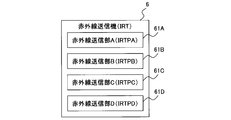
- FIG. 2 is an explanatory diagram of the configuration of the infrared transmitter 6 according to the first embodiment of the present invention.
- the infrared transmitter 6 includes an infrared transmitter A (IRTPA) 61A, an infrared transmitter B (IRTPB) 61B, an infrared transmitter C (IRTPC) 61C, and an infrared transmitter D (IRTPD) (hereinafter collectively referred to as an infrared transmitter). 61).
- IRTPA infrared transmitter A
- IRTPB infrared transmitter B
- IRTPC infrared transmitter C
- IRTPD infrared transmitter D
- These infrared transmitters 61 are arranged in four directions, and transmit infrared data at predetermined time intervals in the order of the infrared transmitter 61A, the infrared transmitter 61B, the infrared transmitter 61C, and the infrared transmitter 61D.
- the infrared data transmitted by each infrared transmission unit 61 includes a unique identifier of the infrared transmission unit 61 that transmits the data.
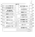
- FIG. 3 is an explanatory diagram of the configuration of the terminal 5 according to the first embodiment of this invention.
- the terminal 5 is a small terminal (for example, a name tag type terminal) that can be worn by a person. Although only one terminal 5 is shown in FIG. 1, a plurality of terminals 5 may exist.
- the terminal 5 receives infrared data transmitted by the infrared transmitter 6 and infrared data transmitted by another terminal 5, and includes a sensing unit (TRSE) 51, a transmission / reception unit (TRSR) 52, An input / output unit (TRIO) 53, a control unit (TRCO) 54, and a recording unit (TRME) 55 are provided.
- TRSE sensing unit
- TRSR transmission / reception unit
- TEO input / output unit
- TRCO control unit
- TRME recording unit
- the transmission / reception unit 52 is a data transfer unit that transmits and receives data to and from the base station 4. For example, when the transmission / reception unit 52 receives a control command transmitted by the base station 4, the transmission / reception unit 52 may transmit the sensing data to the base station 4 or periodically transmit the sensing data regardless of the control command. You may send it.
- the transmission / reception unit 52 when receiving the control command transmitted from the base station 4, the transmission / reception unit 52 changes the control content of the terminal 5 based on the received control command. Further, the transmission / reception unit 52 outputs the content commanded by the received control command to an output device (for example, a display) of the input / output unit 53. Further, the transmission / reception unit 52 transmits the content input via the input device (for example, a button) of the input / output unit 53 to the base station 4 as a control command.
- an output device for example, a display
- the transmission / reception unit 52 transmits the content input via the input device (for example, a button) of the input / output unit 53 to the base station 4 as a control command.
- the sensing unit 51 senses various physical quantities indicating the state of the terminal 5. Specifically, the sensing unit 51 includes one or more sensors that sense various physical quantities.
- the sensing unit 51 includes an infrared transmission unit 511, an infrared reception unit 512 (infrared reception unit A (TRIRA), infrared reception unit B (TRIRB), infrared reception unit C (TRIRC), and infrared reception unit D (TRIRD). )), An acceleration sensor (TRAC) 513, an illuminance sensor (TRIL) 514, an external input (TROU) 515, a temperature sensor (TRTE) 516, and a microphone (TRMI) 517.
- TRIRA infrared reception unit A
- TRIRB infrared reception unit B
- TRIRC infrared reception unit C
- TRIRD infrared reception unit D
- the infrared transmission unit 511 transmits infrared data including a unique identifier of the terminal 5.
- the infrared receiver 512 receives the infrared data transmitted by the infrared transmitter 6 and the infrared data transmitted by the infrared transmitter 511 provided in the other terminal 5.
- the terminal 5 can include a plurality of infrared receiving units 512, and includes four infrared receiving units A to D in FIG.
- the infrared receiving unit 512 makes any one of the infrared receiving unit A, the infrared receiving unit B, the infrared receiving unit C, and the infrared receiving unit D ready to receive infrared data for a predetermined time. ⁇ D is made ready for reception once and this is repeated periodically. Details of the periodic transition of the state of the infrared receiving unit 512 will be described with reference to FIG. 10C.
- the infrared data transmitted by the infrared transmitter 6 is used to specify the position of the terminal 5 with respect to the infrared transmitter 6, and the infrared data transmitted by the infrared transmitter 511 is the same as the terminal 5 that transmitted the infrared data. It is used to detect whether or not another terminal 5 has met.
- the terminal 5 be a name tag type that is worn in front of a person.
- a method of attaching the terminal 5 to a person for example, there is a method of hanging from the person's neck with a string or the like.
- terminal 5 and the other terminal 5 face each other may be detected by transmission / reception of a radio signal other than infrared data.
- the acceleration sensor 513 detects the acceleration of the terminal 5 in the X-axis, Y-axis, and Z-axis directions. Note that the acceleration of the terminal 5 detected by the acceleration sensor 513 is used to determine the intensity of action and behavior of the person wearing the terminal 5 (for example, whether the person is walking or standing still).
- the illuminance sensor 514 detects illuminance, and the temperature sensor 516 detects temperature.
- the illuminance detected by the illuminance sensor 514 and the temperature detected by the temperature sensor 516 are used, for example, for determining the environment around the terminal 5.
- the microphone 517 detects sound. The sound detected by the microphone 517 is used to determine whether or not the person wearing the terminal 5 is talking, for example.
- the external input 515 is an interface through which information detected by a sensor outside the terminal 5 is input.
- the sensing unit 51 may include any one or more of an acceleration sensor 513, an illuminance sensor 514, a temperature sensor 516, and a microphone 517, or may include other types of sensors.
- the sensing unit 51 needs to include a wireless data receiving unit other than the infrared receiving unit 512.
- This wireless data receiving unit may be connected via an external input 515.
- the input / output unit 53 includes an input device such as a button (not shown) and an output device such as a liquid crystal display (not shown). A person wearing the terminal 5 operates the input device to select information to be acquired. In addition, sensing data and the like are displayed on the output device. As the input / output unit 53, a touch panel in which an input device and an output device are integrated may be used.
- the control unit (TRCO) 54 includes a CPU (not shown), and the CPU executes a program stored in the recording unit 55 to control the acquisition timing of various sensor information and the transmission / reception timing to the base station (GW). Then, the acquired sensor information is analyzed.
- the recording unit (TRME) 55 includes an external recording device such as a hard disk, a memory, or an SD card, and stores programs, sensing data, and the like. Further, the recording unit 55 includes a data format (TRDFI) 551 and an internal information unit (TRIN) 552.
- TRDFI data format
- TTN internal information unit
- the data format 551 stores sensing data, sensor information acquired from various sensors, and data specifying a data format for transmitting time information.
- the information regarding the terminal 5 is, for example, battery remaining amount information (TRBA) 553, clock information (TRTI) 554 which is time information, and terminal information (TRTR) 555.
- TRBA battery remaining amount information
- TRTI clock information
- TRTR terminal information
- the battery remaining amount information 553 is information indicating the remaining amount of power of the terminal 5.
- the clock information 554 is information indicating the current time measured by a timer built in the terminal 5. Note that the current time of the terminal 5 is corrected based on time information periodically transmitted from the base station 4. That is, the time of the base station 4 and the time of the terminal 5 are synchronized.
- the terminal information 555 is a unique identifier (unique ID) of the terminal 5.
- the time of the base station 4 and the time of the terminal 5 are synchronized, the time can be synchronized among the plurality of terminals 5. Thereby, the base station 4 can align the sensing data acquired from the different terminals 5 based on the time, and can collate these sensing data.
- the time correction of the terminal 5 may not be triggered by the base station 4.
- the time may be transmitted to the terminal 5 via the base station 4 using the sensor network server 3 as a trigger.
- FIG. 4 is an explanatory diagram of the configuration of the base station 4 according to the first embodiment of this invention.
- the base station 4 collects data from the terminals 5 located in a predetermined range (area) from the base station 4. Specifically, the base station 4 receives sensing data transmitted wirelessly or by wire from the terminal 5 located in the area, and transmits the received sensing data to the sensor network server 3 via the network 7.
- the base station 4 When the terminal 5 transmits the sensing data wirelessly, the base station 4 establishes a connection with the terminal 5 existing within the wireless data reachable range and communicates the data.
- the base station 4 includes a transmission / reception unit (GWSR) 41, a control unit (GWCO) 42, an input / output unit (GWIO) 43, and a recording unit (GWME) 44.
- GWSR transmission / reception unit
- GWCO control unit
- GWIO input / output unit
- GWME recording unit
- the transmission / reception unit 41 transmits / receives data to / from the terminal 5 and the base station 4.
- the transmission / reception unit 41 may transmit a control command to the terminal 5 or may receive sensing data from the terminal 5.
- sensing data of the terminal 5 there are various methods for transmitting sensing data of the terminal 5, and typical methods include a method of transmitting sensing data when receiving a control command from the base station 4, regardless of an end control command. There are a method of periodically transmitting sensing data and a method of transmitting sensing data at the timing when the sensing data is acquired.
- the transmission / reception unit 41 transfers the received control command to the sensor network server 3. Then, the sensor network server 3 transmits data corresponding to the received control command to the base station 4. The transmission / reception unit 41 receives the data transmitted by the sensor network server 3 and transfers the received data to the terminal 5.
- the transmission / reception unit 41 may transmit the content input from an input device (not shown) of the input / output unit 43 (for example, a button or a keyboard) to the terminal 5 and the sensor network server 3 as a control command. Further, the transmission / reception unit 41 may receive a control command transmitted from the terminal 5 or the sensor network server 3.
- the base station 4 When the transmission / reception unit 41 receives a control command, the base station 4 changes the display content of an output device (for example, a liquid crystal display) of the input / output unit 43 based on the received control command.
- an output device for example, a liquid crystal display
- the control unit 42 includes a CPU (not shown).
- the CPU executes a program stored in the recording unit 44 to control transmission / reception timing of various data to the terminal 5 and the sensor network server 3 and analyze the various data.
- the input / output unit 43 includes an input device such as a button or a keyboard (not shown) and an output device such as a liquid crystal display (not shown). Information such as the status of the terminal 5 in the area and sensing data are output to the output device.
- an input device such as a button or a keyboard (not shown)
- an output device such as a liquid crystal display (not shown).
- Information such as the status of the terminal 5 in the area and sensing data are output to the output device.
- a touch panel in which an input device and an output device are integrated may be used as the input / output unit 43.
- the recording unit 44 includes an external recording device such as a hard disk, a memory, or an SD card, and stores programs and sensing data.
- the sensing data includes reception results of infrared data from the infrared transmitter 6 of the terminal 5 and reception results of infrared data from other terminals of the terminal 5.
- the recording unit 44 includes a data format (GWDFI) 441 and an internal information unit (GWIN) 442.
- the data format 441 stores data specifying a data format for specifying a data format such as sensing data received from the terminal 5. Each element of the data received from the terminal 5 is determined based on the data format stored in the data format 441.
- the internal information unit 442 stores data related to the base station 4.
- the data related to the base station 4 is, for example, clock information (GWTI) 443 that is time information and base station information (GWBA) 444 that is a unique identifier of the base station 4.
- GWTI clock information
- GWBA base station information
- FIG. 5 is an explanatory diagram of the configuration of the sensor network server 3 according to the first embodiment of this invention.
- the sensor network server 3 receives the sensing data transmitted by the base station 4, stores the received sensing data, and generates a sensing table 1100 (see FIG. 11C).
- the sensor network server 3 receives the sensing data acquisition request transmitted by the application server 1 and transmits sensing data to the application server 1 based on the received sensing data acquisition request.
- the sensor network server 3 receives the control command transmitted by the base station 4 and transmits data specified by the received control command to the base station 4.
- the sensor network server 3 includes a transmission / reception unit (SSSR) 31, a control unit (SSCO) 32, an input / output unit (SSIO) 33, a recording unit (SSME) 34, and a database unit (SSDB) 35.
- SSSR transmission / reception unit
- SSCO control unit
- SSIO input / output unit
- SSME recording unit
- SSDB database unit
- the database unit 35 stores a sensing table 1100 generated from sensing data transmitted by the base station 4.
- the database unit 35 stores processing corresponding to the control command from the base station 4.
- the database unit 35 may be included in the recording unit 34.
- the control unit 32 includes a CPU (not shown).
- the CPU executes the program stored in the recording unit 34, the management process of the database unit 35, the sensing data transmission process corresponding to the sensing data acquisition request from the application server 1, the sensing data transmitted by the base station 4 Are stored in the database unit 35 and a process corresponding to the control command from the base station 4 is executed.
- the transmission / reception unit 31 transmits various data to the base station 4 and the application server 1 and receives various data from the base station 4 and the application server 1. For example, the transmission / reception unit 31 receives sensing data transmitted from the base station 4 and transmits the sensing data to the application server 1. Further, when receiving a control command from the base station 4, the transmission / reception unit 31 transmits the execution result of the process corresponding to the received control command to the base station 4.
- the input / output unit 33 includes an input device such as a button or a keyboard (not shown) and an output device such as a liquid crystal display (not shown).
- the output device displays information indicating the status of the base station 4 and the terminal 5 and the collected sensing data.
- a touch panel in which an input device and an output device are integrated may be used.
- the recording unit 34 includes an external recording device such as a hard disk, a memory, or an SD card, and stores programs and sensing data. Further, the recording unit 34 includes a data format (SSDFI) 341.
- SSDFI data format
- the data format 341 stores data specifying a data format such as sensing data received from the base station 4. Each element of data received from the base station 4 is determined based on the data format stored in the data format 341.
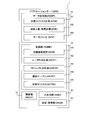
- FIG. 6 is an explanatory diagram of the configuration of the application server 1 according to the first embodiment of this invention.
- the application server 1 is a computer that collects sensing data from the sensor network server 3 and executes processing for specifying the position of the terminal 5 based on the collected sensing data.
- the application server 1 includes a data processing unit (ASDP) 15, a control unit (ASCO) 12, a recording unit (ASME) 14, a transmission / reception unit (ASSR) 11, and an input / output unit (ASIO) 13.
- ASDP data processing unit
- ASCO control unit
- ASME recording unit
- ASSR transmission / reception unit
- ASIO input / output unit
- the function of the application server 1 may be implemented in the client 2 and the sensor network server 3.
- the data processing unit 15 identifies the position of the terminal 5 based on the collected sensing data, and generates an image indicating organizational communication.
- the data processing unit 15 executes a face-to-face matrix calculation (APIM) 151, a face-to-face number / time calculation (APIC) 152, and a data plot (APIP) 153.
- APIM face-to-face matrix calculation
- APIC face-to-face number / time calculation
- APIP data plot
- the data processing unit 15 is realized, for example, when the control unit 12 executes a program stored in the recording unit 14. In this case, each process of the data processing unit 15 (meeting matrix calculation 151, meeting number / time calculation 152, data plot 153) is executed by a CPU (not shown) of the control unit 12.
- the data processing unit 15 temporarily stores data generated by the processing to be executed in the recording unit 14.
- the face-to-face matrix calculation 151 identifies the face-to-face direction of each terminal 5 with respect to the infrared transmitter 6 based on the collected sensing data.
- the face-to-face number / time calculation 152 specifies the number of terminals 5 that have received infrared data from the infrared transmitter 6 and the time that each terminal 5 has received infrared data from the infrared transmitter 6.
- the data plot 153 generates an image in which each terminal 5 is plotted at the position specified by the face-to-face matrix calculation 151.
- the control unit 12 includes a CPU (not shown).
- the CPU executes the program stored in the recording unit 14, transmits the sensing data acquisition request to the sensor network server 3, the position specifying process of the terminal 5 based on the sensing data, and the management process of the execution result of the position specifying process Etc.
- the recording unit 14 includes an external recording device (not shown) such as a hard disk, a memory, or an SD card, and stores execution results of various processes.
- an external recording device such as a hard disk, a memory, or an SD card
- the recording unit 14 stores values used for various processes. These values are an initial condition setting (ASSII) 141, a user ID correspondence table (ASUIT) 142, a project correspondence table (ASPUT) 143, a join table (ASCNT) 144, a facing matrix (ASTMX) 145, and the like.
- ASSII initial condition setting
- ASUIT user ID correspondence table
- ASPUT project correspondence table
- ASCNT join table
- ASTMX facing matrix
- the initial condition setting 141 is a value indicating the initial condition of the application server 1.
- the user ID correspondence table 142 is a table including values for managing the ID of the terminal 5 and the ID of the user wearing the terminal 5.
- the project correspondence table 143 is a table composed of values for managing each user and the project to which each user belongs.
- the combination table 144 is a table (the sensing table 1100 shown in FIG. 11) in which the sensing data received from the sensor network server 3 is combined.
- the face-to-face matrix 145 is a processing result by the face-to-face matrix calculation 151.
- the user ID correspondence table 142 and the project correspondence table 143 may be recorded in the recording unit 34 of the sensor network server 3.
- the user ID correspondence table 142 and the project correspondence table 143 may be directly described in the program. However, by recording the user ID correspondence table 142 and the project correspondence table 143 separately from the program, the user change, the terminal 5 It is possible to flexibly deal with changes in IDs and changes in the organizational structure of projects.
- the value stored in the recording unit 14 can be added, deleted, or changed according to the type of data and the type of processing.
- the transmission / reception unit (ASSR) 11 receives sensing data from the sensor network server 3.
- the transmission / reception unit 11 receives a processing request from the client 2 and transmits a processing result corresponding to the received processing request to the client 2.
- the input / output unit (ASIO) 13 includes an input device such as a button or a keyboard and an output device such as a liquid crystal display. On the output device, the status of the area for which the position of the terminal 5 is to be identified and the sensing data are displayed.
- an input device such as a button or a keyboard
- an output device such as a liquid crystal display.
- the status of the area for which the position of the terminal 5 is to be identified and the sensing data are displayed.
- a touch panel in which an input device and an output device are integrated may be used.
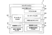
- FIG. 7 is an explanatory diagram of the configuration of the client 2 according to the first embodiment of this invention.
- the client 2 When the client 2 receives the organization communication presentation request from the user via the mouse (CLIM) 232 or the keyboard (CLIK) 233, the client 2 transmits the organization communication presentation request to the application server 1 via the network 7. Then, the client 2 receives the organizational communication data that is the processing result of the transmitted organizational communication presentation request from the application server 1 via the network 7 and displays the received organizational communication data on the display 231.
- CLIM mouse
- CLIK keyboard
- the client 2 includes a transmission / reception unit (CLSR) 21, an input / output unit (CLIO) 23, a recording unit (CLME) 24, and a control unit (CLCO) 22.
- CLSR transmission / reception unit
- CLIO input / output unit
- CLME recording unit
- CLCO control unit
- the control unit 22 includes a CPU (not shown) that executes a program stored in the recording unit 24.
- the control unit 22 adjusts the size or the like of the image indicating the processing result based on a request from the user, and displays the adjusted image or the like. Displayed on an output device such as H.231.
- the transmission / reception unit 21 transmits a data processing request and receives a processing result of the data processing request (that is, organization communication data).
- the input / output unit 23 includes an input device such as a mouse (CLIM) 232 and a keyboard (CLIK) 233, and an output device such as a display (CLWD) 231.
- the input / output unit 23 receives an organization communication presentation request via the input device, and receives organization communication. Output data to the output device.
- An external input / output (CLOU) 234 is an interface for connecting input / output devices other than the display 231, the mouse 232, and the keyboard 233.
- the recording unit includes an external recording device such as a hard disk, a memory, or an SD card, and stores the main program, sensing data, organization communication data received from the application server 1, and processing results by the control unit 22.
- the initial condition setting (CLISI) 241 stored in the recording unit 24 is set with conditions set by the user (for example, the size of an image when displaying organization communication data).
- FIG. 8 is an explanatory diagram of the arrangement of the infrared transmitter 61 in the infrared transmitter 6 according to the first embodiment of the present invention.
- infrared transmitter 6 In FIG. 2, four infrared transmitters 61 are illustrated, but the number of infrared transmitters 61 provided in the infrared transmitter 6 may be any number.
- the infrared transmitter 6 shown in FIG. 8 includes twelve infrared transmitters 61A to 61L, and transmits infrared data in twelve directions.
- the substrate 62 of the infrared transmitter 6 is a regular dodecagon, and each of the infrared transmitters 61A to 61L is arranged in parallel to each side of the substrate 62.
- the number of sides of the substrate 62 and the number of infrared transmitters 61 are not limited to twelve.
- FIG. 9 is a block diagram of the infrared transmitter 6 according to the first embodiment of the present invention.
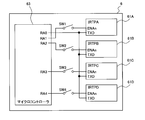
- the infrared transmitter 6 shown in FIG. 9 includes four infrared transmitters 61A to 61D and a microcontroller 63.
- the microcontroller 63 controls the transmission timing of the infrared data of each of the infrared transmission units 61A to 61D.
- the microcontroller 63 has RA0 to RA4 terminals, and each infrared transmitter 61A to 61D has an ENAn terminal and a TXD terminal.
- the RA0 terminal of the microcontroller 63 is connected to the TXD terminals of the infrared transmitters 61A to 61D, and an infrared data transmission command is output from the RA0 terminal.
- the RA1 terminal is connected to the ENAn terminal of the infrared transmission unit 61A via the switch SW1.
- the RA2 terminal is connected to the ENAn terminal of the infrared transmission unit 61B via the switch SW2.
- the RA3 terminal is connected to the ENAn terminal of the infrared transmission unit 61C via the switch SW3.
- the RA4 terminal is connected to the ENAn terminal of the infrared transmission unit 61D via the switch SW4.
- An enable signal is output from the RA1 terminal to RA4 terminal.
- the infrared transmitters 61A to 61D take in the transmission command input to the TXD terminal, and when the enable signal is not input to the ENAn terminal, the infrared transmitters 61A to 61D Does not capture commands. That is, the microcontroller 63 outputs an enable signal to the ENAn terminal of the infrared transmission unit 61 when the infrared transmission unit 61 transmits infrared data.
- switches SW1 to SW4 are connected between the RA1 terminal to RA4 terminal of the microcontroller 63 and the ENAn terminals of the infrared transmission units 61A to 61D, respectively. These switches SW1 to SW4 switch the connection between the RA1 terminal to RA4 terminal and the ENAn terminal of each of the infrared transmitters 61A to 61D to a connected state or a non-connected state. Note that these switches SW1 to SW4 can be manually switched between a connected state and a non-connected state.
- the infrared transmission unit 61 enters an effective state in which infrared data can be transmitted.
- the switches SW1 to SW4 are provided between the RA1 terminal to the RA4 terminal and the infrared transmission units 61A to 61D, the unnecessary infrared transmission units 61A to 61D are set in an invalid state in which infrared data is not transmitted. Since infrared data is not transmitted from the unnecessary infrared transmitters 61A to 61D, the power consumption of the infrared transmitter 6 can be reduced.
- the transmission timing of the infrared transmitter 61 provided in the infrared transmitter 6 and the reception timing of each infrared receiver 512 provided in the terminal 5 will be described with reference to FIGS. 10A to 10C.
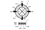
- FIG. 10A is an explanatory diagram of a positional relationship between the infrared transmitter 6 and the terminal 5 according to the first embodiment of this invention.
- the infrared transmitter 6 includes four infrared transmitters 61A to 61D, and transmits infrared data in four directions from A direction to D direction.
- the terminal 5 includes four infrared receivers 512A to 512D and is positioned in the A direction of the infrared transmitter 6. The reason why the terminal 5 includes the plurality of infrared receiving units 512 is to increase the receivable range of infrared data.
- the terminal 5 Since the terminal 5 is located in the direction A of the infrared transmitter 6, it receives only the infrared data transmitted by the infrared transmitter 61A, and does not receive the infrared data transmitted by the other infrared transmitters 61B to 61D.
- FIG. 10B is an explanatory diagram of the transmission timing of the infrared data of the infrared transmitters 61A to 61D provided in the infrared transmitter 6 according to the first embodiment of the present invention.
- the infrared transmitter 6 transmits infrared data simultaneously from a plurality of infrared transmitters 61A to 61D, a voltage for transmitting the infrared data must be applied to the infrared transmitters 61A to 61D.
- one of the infrared transmission units 61 transmits infrared data at a period of t seconds in the order of the infrared transmission units 61A, 61B, 61C, and 61D. That is, after the infrared transmission unit 61A transmits the infrared data (IRt1), the infrared transmission unit 61B transmits the infrared data after t seconds (IRt2).
- FIG. 10C is an explanatory diagram of state transitions of the infrared receiving unit 512 included in the terminal 5 according to the first embodiment of this invention.
- the terminal 5 periodically switches the infrared receiving unit 512 to the normal operation mode or the standby mode.
- the normal operation mode is a mode in which any one infrared receiving unit 512 can receive infrared data.
- the standby mode is a mode in which none of the infrared receivers 512 can receive infrared data, and the power consumption in the standby mode is lower than the power consumption in the normal operation mode.
- any one of the infrared receivers 512 is in a receivable state at a T1 second period, and the other infrared receivers 512 are in a standby state. As a result, not all the infrared receivers 512 can be received simultaneously, so that power consumption can be reduced.
- the terminal 5 switches between the normal operation mode and the standby mode based on the time of the clock information 554 synchronized with the time of the base station 4, the switching timing of the normal operation mode or the standby mode is synchronized between the terminals 5.
- the switching timing between the normal operation mode and the standby mode of the terminal 5 and the infrared data transmission timing of the infrared transmitter 6 are not synchronized.
- the terminal 5 transmits infrared data including its own ID only during the normal operation mode, and does not transmit it during the standby mode.
- the infrared transmitter 6 does not transmit infrared data from all the infrared transmission units 61A to 61D while the terminal 5 is in the normal operation mode capable of receiving infrared data, the terminal 5 from the infrared transmission unit 61 where the terminal 5 is present. Despite being located in an area where infrared data can be received, there is a possibility that infrared data from the infrared transmission unit 61 cannot be received. For this reason, the certainty of reception of the infrared data of the terminal 5 cannot be ensured, and the position of the terminal 5 cannot be specified accurately.
- the transmission cycle t of the infrared transmitter 61 and the infrared receiver are set so that the transmission of infrared data from all the infrared transmitters 61A to 61D is completed.
- 512 reception cycle T1 needs to be set.
- the transmission cycle t and the reception cycle T1 are expressed by Equation 1. It is set so that the relationship is established. (Formula 1) T1> m ⁇ t / n 10A to 10C, since the terminal 5 includes four infrared receivers 512 and the infrared transmitter 6 includes four infrared transmitters 61, T1> t is satisfied, that is, the transmission cycle t is received. The transmission cycle t and the reception cycle T1 are set so as to be shorter than the cycle T1.
- 10B and 10C show a state in which the reception cycle T1 of the infrared receiving unit 512 is approximately twice as long as that of the infrared transmitting unit t.
- the infrared receiving unit 512A of the terminal 5 is in a receivable state (IRr1)
- the infrared transmitting unit 61B transmits infrared data in the B direction (IRt2)
- the infrared transmitting unit 61C transmits the infrared data. Transmit in direction C (IRt3).
- the terminal 5 is not located in the B direction and the C direction of the infrared transmitter 6, it does not receive infrared data during IRr1.
- the infrared transmitting unit 61D transmits infrared data in the D direction (IRt3).
- the terminal 5 since the terminal 5 is not located in the direction D of the infrared transmitter 6, it does not receive infrared data during IRr2.
- the infrared receiver 512C of the terminal 5 While the infrared receiver 512C of the terminal 5 is in a receivable state (IRr3), the infrared transmitter 61A transmits infrared data in the A direction (IRt5), and the infrared transmitter 61B transmits infrared data in the B direction (IRt6). ). Since the terminal 5 is located in the A direction of the infrared transmitter 6, the infrared receiver 512 ⁇ / b> C receives the infrared data transmitted from the infrared transmitter A.
- the infrared transmission unit 61C transmits infrared data in the C direction (IRt7), and the infrared transmission unit 61D transmits the infrared data in the D direction (IRt8).
- the terminal 5 since the terminal 5 is not located in the C direction and the D direction, it does not receive infrared data during IRr4.
- infrared receiving unit 512 of the terminal 5 is in a receivable state (IRr3), infrared data from the A direction of the infrared transmitter 6 where the terminal 5 is located is received.
- the transmission of the infrared data from all of the infrared transmission units 61A to 61D is completed, so that the terminal 5 is located in a certain direction of the infrared transmitter 6
- infrared data transmitted in the direction can be always received during one normal operation mode.
- the terminal 5 enters the standby mode for T2 seconds after the infrared receiving unit 512D is ready for reception (IRr4), and the infrared receiving unit 512A is again ready for reception.
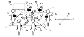
- FIG. 11A is an explanatory diagram of a positional relationship between the member wearing the terminal 5 and the infrared transmitter 6 according to the first embodiment of this invention.
- the infrared transmitter 6 is arranged at the center of the table 111.
- Infrared transmitter 61 located in the N direction (north direction) of infrared transmitter 6 transmits infrared data including ID “01”.
- the infrared transmission unit 61 located in the E direction (east direction) transmits infrared data including ID “02”.
- the infrared transmission unit 61 located in the S direction (south direction) transmits infrared data including ID “03”.
- the infrared transmission unit 61 located in the W direction (west direction) transmits infrared data including ID “04”.
- the ID transmitted by each infrared transmitter 61 included in the infrared data is set when the infrared transmitter 6 is turned on so as to correspond to the direction.
- the infrared transmitter 6 includes a direction detection unit such as a azimuth magnetic needle, and specifies the direction in which each infrared transmission unit 61 is located based on the direction detected by the direction detection unit when the power is turned on.
- the infrared transmission unit 61 is set so as to transmit the infrared data including the ID corresponding to the designated direction.
- “01” corresponds to the N direction
- “02” corresponds to the S direction
- “03” corresponds to the E direction
- “04” corresponds to the W direction. It is assumed that the application server 1 and the sensor network server 3 are set in advance with a table indicating this correspondence.
- the six members wearing the terminal 5 surrounding the table 111 hold a meeting.
- the six members are each equipped with the terminals 5a to 5f, and the terminal 5a transmits infrared data including the ID “0a”.
- the terminal 5b transmits infrared data including the ID “0b”.
- the terminal 5c transmits infrared data including the ID “0c”.
- the terminal 5d transmits infrared data including the ID “0d”.
- the terminal 5e transmits infrared data including the ID “0e”.
- the terminal 5f transmits infrared data including the ID “0f”.
- a white board 112 is arranged in the N direction of the infrared transmitter 6.
- the infrared transmitter 6 periodically transmits infrared data from each infrared transmitter 61, and the terminal 5 receives the infrared data transmitted in the direction in which the terminal 5 is located, and converts the received infrared data into the received infrared data.
- the included ID and reception time are stored as a reception result.
- the terminal 5 periodically transmits infrared data including its own ID while in the normal operation mode.
- the terminal 5 meets the other terminal 5 within a predetermined distance, the terminal 5 receives the infrared data transmitted by the other terminal 5, and stores the ID and the reception time included in the received infrared data as the reception result. To do.
- FIG. 11B is an explanatory diagram of a reception result collection method according to the first embodiment of this invention.
- the member wearing the terminal 5 inserts the worn terminal 5 into the multi-cradle 8 when returning home.
- the terminal 5 transmits a reception result including its own ID to the base station 4.
- the terminal 5 is charged when inserted into the multi-cradle 8.
- the base station 4 Upon receiving the reception result, the base station 4 transmits the received reception result to the sensor network server 3 via the network 7.
- the sensor network server 3 When receiving the reception result, the sensor network server 3 generates a sensing table 1100 (see FIG. 11C) and stores it in the database unit 35. Then, the sensor network server 3 transmits the generated sensing table 1100 to the application server 1.
- the application server 1 When the application server 1 receives the sensing table 1100, the application server 1 generates organization communication (see FIG. 11D) based on the received sensing table 1100.
- FIG. 11C is an explanatory diagram of the sensing table 1100 according to the first embodiment of this invention.
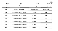
- the sensing table 1100 includes ID 1101, sensing time 1102, facing data 1103, and facing direction 1104.
- ID 1101 a unique identifier of the terminal 5 is registered.
- the sensing time 1102 registers the time when the terminal 5 received the infrared data.
- IDs ID of the infrared transmission unit 61 and IDs of other terminals 5 included in the infrared data received by the terminal 5 are registered.
- facing direction 1104 the direction corresponding to the ID included in the received infrared data is registered.
- ID 1101 sensing time 1102, and face-to-face data 1103, the ID of the terminal 5, the reception time, and the ID of infrared data included in the reception result received by the sensor network server 3 are registered.
- the sensor network server 3 Since the sensor network server 3 stores information indicating the correspondence between the IDs “01” to “04” of the infrared data and the direction, the sensor network server 3 specifies the direction from the ID of the infrared data included in the reception result. The registered direction is registered in the facing direction 1104.
- the terminal 5a with ID 0a receives infrared data including ID “01” at 12:35:40 on March 10, 2010. Further, since the infrared data including the ID “01” is transmitted from the N-direction infrared transmitter 61, it is determined that the terminal 5a is located in the N direction of the infrared transmitter 6.
- the terminal 5b whose ID is 0b receives infrared data including the ID “01” on March 10, 2010 at 12:35:40. Further, since the infrared data including ID “01” is transmitted from the N-direction infrared transmission unit 61, it is determined that the terminal 5 b is located in the N direction of the infrared transmitter 6.
- the terminal 5c with ID 0c is receiving infrared data including ID “02” at 10:35:40 on March 10, 2010. Further, since the infrared data including ID “02” is transmitted from the infrared transmission unit 61 in the E direction, the terminal 5 c is determined to be located in the E direction of the infrared transmitter 6.
- the terminal 5d whose ID is 0d is receiving infrared data including the ID “03” at 12:35:40 on March 10, 2010. Further, since the infrared data including the ID “03” is transmitted from the infrared transmission unit 61 in the S direction, the terminal 5 d is determined to be located in the S direction of the infrared transmitter 6.
- the terminal 5e with the ID 0e receives infrared data including the ID “03” at 12:35:40 on March 10, 2010. Further, since the infrared data including the ID “03” is transmitted from the infrared transmission unit 61 in the S direction, it is determined that the terminal 5 e is located in the S direction of the infrared transmitter 6.
- the terminal 5f with ID 0f is receiving infrared data including ID “04” at 12:35:40 on March 10, 2010. Further, since the infrared data including the ID “04” is transmitted from the infrared transmission unit 61 in the W direction, it is determined that the terminal 5 f is located in the W direction of the infrared transmitter 6.
- the terminal 5b receives infrared data including the ID “0c” (the ID of the terminal 5c) at 12:35:40 on March 10, 2010.
- the terminal 5a located in the same N direction as the terminal 5b has not received the infrared data including the ID “0c”. Accordingly, the terminal 5b is located closer to the terminal 5c than the terminal 5a.
- the terminal 5d receives infrared data including the ID “0c” (the ID of the terminal 5c) at 12:35:40 on March 10, 2010.
- the terminal 5e located in the same S direction as the terminal 5d has not received the infrared data including the ID “0c”. Accordingly, the terminal 5d is located closer to the terminal 5c than the terminal 5e.
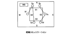
- FIG. 11D is an explanatory diagram of organization communication according to the first embodiment of this invention.
- the application server 1 When the application server 1 receives the sensing table 1100 from the sensor network server 3, the application server 1 generates organizational communication based on the received sensing table 1100.
- the terminals 5 that have received the infrared data including the IDs of the terminals 5 are connected with a line.
- the terminal 5a and the terminals 5e and 5f are connected by a line
- the terminal 5b and the terminal 5c are connected by a line
- the terminal 5c and the terminal 5d are connected by a line.
- the infrared transmitter 61 of the infrared transmitter 6 transmits infrared data including an ID indicating the direction of the infrared transmitter 61, the absolute position where the terminal 5 is located regardless of the direction of the infrared transmitter 6.
- the direction can be specified.
- the position of the whiteboard 112 can also be determined by organizational communication. Can be reproduced.
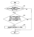
- FIG. 12 is a flowchart of organizational communication generation processing executed by the application server 1 according to the first embodiment of this invention.
- the organization communication generation process is executed by a CPU (not shown) of the application server 1.
- the timing at which the organization communication generation process is executed includes, for example, the timing at which the application server 1 receives an organization communication generation request from the client 2 and the timing at which the sensing table 1100 is received from the sensor network server 3.
- the application server 1 extracts an entry of the time registered in the sensing time 1102 of the sensing table 1100 received from the sensor network server 3 (hereinafter referred to as the same time entry). Then, the application server 1 converts the ID of the terminal 5 registered in the ID 1101 included in the extracted simultaneous entry into the infrared transmitter 6 based on the direction registered in the facing direction 1104 included in the extracted simultaneous entry. (1201).
- time for extracting the same time entry is, for example, the time designated by the user of the client 2.
- a predetermined range of time may be regarded as the same time.
- the application server 1 determines whether there are a plurality of terminals 5 (hereinafter referred to as proximity terminals 5) that have received infrared data from the same infrared transmitter 61 at the same time (1202). Specifically, the application server 1 determines whether there are a plurality of entries in which the same direction is registered in the facing direction 1104 among the entries at the same time.
- step 1202 If it is determined in step 1202 that there is a proximity terminal 5, the application server 1 indicates the detailed location of the proximity terminal 5, that is, a plurality of terminals 5 located in the same direction, and the proximity where the proximity terminal 5 has received infrared data. In order to specify based on the direction of the terminal 5 other than the terminal 5, the processing of steps 1203 to 1205 is executed.
- step 1202 If it is determined in step 1202 that there is no adjacent terminal 5, the process proceeds to step 1206.
- the application server 1 determines whether there is a terminal 5 that has received infrared data from a terminal 5 other than the proximity terminal 5 at the same time among the proximity terminals 5. Is determined (step 1203). Specifically, the application server 1 includes an entry in which ID included in infrared data transmitted from the terminal 5 is registered in the facing data 1103 among a plurality of entries registered in the facing direction 1104 in the same direction. It is determined whether or not.
- step 1203 If it is determined in step 1203 that there is no terminal 5 that has received infrared data from a terminal 5 other than the proximity terminal 5 at the same time among the proximity terminals 5, the detailed position of the proximity terminal 5 cannot be specified. The process proceeds to 1206.
- step 1203 If it is determined in step 1203 that there is a terminal 5 that has received infrared data from a terminal 5 other than the neighboring terminal 5 at the same time among the neighboring terminals 5, the application server 1 transmits infrared data to the neighboring terminal 5. It is determined whether or not the received terminal 5 has received infrared data from any of the infrared transmitters 61 (1204). Specifically, the application server 1 sets the ID of the terminal 5 registered in the ID 1101 among the entries at the same time to the facing data 1103 of the entry that matches the ID of the terminal 5 that transmitted the infrared data to the proximity terminal 5. It is determined whether or not an ID included in the infrared data transmitted from the infrared transmission unit 61 is registered.
- step 1204 If it is determined in step 1204 that the terminal 5 that has transmitted infrared data to the proximity terminal 5 has not received infrared data from any infrared transmission unit 61, the terminal that has transmitted the infrared data received by the proximity terminal 5 Since 5 is not located near the infrared transmitter 6, the application server 1 determines that the reception of the infrared data of the proximity terminal 5 is an erroneous reception, and proceeds to the processing of step 1206.
- step 1204 If it is determined in step 1204 that the terminal 5 that has transmitted infrared data to the proximity terminal 5 has received infrared data from any of the infrared transmission units 61, the application server 1 determines that the proximity terminal 5 among the proximity terminals 5.
- the terminal 5 that has received the infrared data from the other terminals 5 is plotted closer to the terminal 5 that has transmitted the infrared data than the terminal 5 that has not received the infrared data among the neighboring terminals 5 (1205).
- the application server 1 generates an organization communication image for displaying on the client 2 the relationship between the infrared transmitter 6 plotted in the processing of step 1201 or 1205 and the terminal 5 plotted with the infrared transmitter 6 as the center. (1206), the organization communication generation process is terminated.
- infrared transmitter 6 intermittently transmits infrared data from a plurality of infrared transmitters 61.
- FIG. 13A is an explanatory diagram of changes in the Vdd current when a plurality of infrared transmission units 61 of the infrared transmitter 6 transmit infrared data simultaneously.
- 13A includes four infrared transmission units 61A to 61D, and the infrared transmission units 61A to 61D transmit infrared data at the same timing.
- VddPI peak current value
- the infrared data transmission timings of the infrared transmitters 61A to 61D are the same, the peak current (VddPI) of the Vdd line of the infrared transmitter 6 becomes extremely large. This will cause a decrease in transmission distance.
- FIG. 13B is an explanatory diagram of a change in Vdd current when a plurality of infrared transmission units 61 according to the first embodiment of the present invention periodically transmit infrared data.
- infrared data is periodically transmitted so that the transmission timings of the infrared transmission units 61A to 61D do not become the same timing.
- the peak current (VddPI) of the Vdd line of the infrared transmitter 6 is dispersed to the transmission timing of each of the infrared transmitters 61A to 61D, the peak current (VddPI) of the Vdd line is extremely large as shown in FIG. 13A. It can be prevented from becoming large.
- FIG. 14 is an explanatory diagram of an installation mode of the infrared transmitter 6 according to the first embodiment of the present invention.
- the infrared transmitter 6 is placed on the stand 147.
- the stand 147 includes a tripod 148, and the height of the stand 147 can be adjusted by adjusting the length of the tripod 148.
- the length of the tripod 148 is adjusted so that the position of the infrared transmitter 6 is located above the surface of the desk.
- the vertical upward infrared reachable range of the infrared transmitter 6 is not blocked by the desk, the vertically upward reachable distance of the infrared data of the infrared transmitter 6 can be increased.
- the time until all the infrared receivers 512 of the terminal 5 are ready to receive once is determined from the time until all the infrared transmitters 61 of the infrared transmitter 6 transmit the infrared data once. Since the infrared data transmitted by the infrared transmission unit 61 in the direction in which the terminal 5 is located can always be received while the infrared reception unit 512 is in a receivable state, the direction in which the terminal 5 is located is set. The infrared transmitter 61 can ensure that the infrared receiver 512 receives the infrared data, and the position of the terminal 5 can be accurately grasped.
- a member wearing a terminal 5 using an infrared transmitter 6 in a member replacement conference method in which members other than the host role (summary role) of each table are switched at a predetermined time interval.
- a member replacement conference method conference method by a world cafe
- members other than the host role (summary role) of each table are switched at a predetermined time interval.
- World Museum is a method of discussion based on the idea that ideas are created from conversations in an open and relaxed environment like a café.
- a theme is created by spreading ideas like pollen pollination.
- a collaborative discussion is possible.
- each table has a single host. And the member located in the table exchanges opinions about a predetermined theme mentally. In addition, imitation paper is placed on the table, and each member freely takes notes on the imitation paper.
- each host When one session is set to 20 minutes, for example, and the first session ends, members other than the host move to other tables apart. After the second session, each member introduces the opinions discussed at the table at the last time, and further exchanges opinions on a predetermined theme.
- each host collects and announces the opinions that appear in each table, and the conference by the World cafe ends.
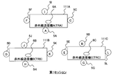
- FIG. 15A is an explanatory diagram of a positional relationship between a table and members during the first session according to the second embodiment of this invention.
- the infrared transmitter 6A is installed, the member A wearing the terminal 5A, the member C wearing the terminal 5C, the member I wearing the terminal 5I, and the member wearing the terminal 5F. F is located.
- an infrared transmitter 6B is installed on the table 111B in the first session, and the member H wearing the terminal 5H, the member K wearing the terminal 5K, the member J wearing the terminal 5J, and the terminal 5D are installed. Member D is located.
- an infrared transmitter 6C is installed on the table 111C in the first session, and the member H wearing the terminal 5H, the member K wearing the terminal 5K, the member J wearing the terminal 5J, and the terminal 5D are installed. Member D is located.
- FIG. 15B is an explanatory diagram of a positional relationship between a table and members during the n-th session according to the second embodiment of this invention.
- the member A wearing the terminal 5A, the member K wearing the terminal 5K, the member I wearing the terminal 5I, and the member F wearing the terminal 5F are located.
- the member F wearing the terminal 5F, the member C wearing the terminal 5C, the member E wearing the terminal 5E, and the member D wearing the terminal 5D are located. .
- the member J wearing the terminal 5J, the member H wearing the terminal 5H, the member B wearing the terminal 5B, and the member L wearing the terminal 5L are located. .
- the infrared data transmitted from the infrared transmitter 61 of the infrared transmitter 6 used in the world cafe includes the unique identifier of the infrared transmitter 6 in addition to the unique identifier of the infrared transmitter 61.
- the application server 1 sends the reception result of the infrared data from the terminal 5 (sensing table 1110, see FIG. 16) via the sensor network server 3. Collect.
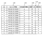
- FIG. 16 is an explanatory diagram of the sensing table 1110 according to the second embodiment of this invention.
- the sensing table 1110 shown in FIG. 16 is a result of receiving infrared data of the terminal 5 at the time during the first session shown in FIG. 15A.
- the sensing table 1110 includes ID 1101, sensing time 1102, infrared transmitter ID 1105, facing data 1103, and facing direction 1104.
- ID 1101, sensing time 1102, facing data 1103, and facing direction 1104 are the same as the sensing table 1100 shown in FIG.
- the infrared transmitter ID 1105 a unique identifier of the infrared transmitter 6 including the infrared transmitter 61 included in the infrared data transmitted from each infrared transmitter 61 is registered.
- the IDs of the facing terminals 5 are not registered, but the terminals 5 face each other at a predetermined distance or less. In this case, the ID of the terminal 5 that has been faced is registered.
- Application server 1 executes organization communication generation processing shown in FIG. 12 using sensing table 1110 received from sensor network server 3.
- the application server 1 plots the terminals 5 having the same identifier of the infrared transmitter 6 registered in the infrared transmitter ID 1105 included in the sensing table 1110 with the infrared transmitter 6 as the center.
- the application server 1 also collects voice data collected by the microphone 517 of the terminal 5, it can grasp the excitement of the discussion of the table of each session.
- FIG. 17 is a flowchart of host specifying processing executed by the application server 1 according to the second embodiment of this invention.
- the host specifying process may be executed, for example, after the execution of the process of step 1206 in the organization communication generation process shown in FIG. 12 or executed when the application server 1 receives a host specifying request from the client 2. May be.
- the application server 1 determines whether there is a terminal 5 that continuously receives infrared data from the same infrared transmitter 6 for a predetermined time or more (1701).
- step 1701 The processing in step 1701 will be specifically described.
- the application server 1 stores a sensing table 1110 over a plurality of sessions as a premise.
- the application server 1 sorts the sensing table 1110 in the order of the identifiers of the terminals 5 registered in the ID 1101, and the identifier of the same infrared transmitter 6 is registered in the infrared transmitter ID 1105 from the entry in which the identifier of the same terminal 5 is registered in the ID 1101. Extract the entries. Then, the application server 1 refers to the sensing time 1102 of the extracted entry, and determines whether or not the identifier of the same infrared transmitter 6 is continuously registered in the infrared transmitter ID 1105 for a predetermined time or more.
- the predetermined time for the processing in Step 1701 is set to be longer than the time until at least two sessions are completed.
- step 1701 If it is determined in step 1701 that there is no terminal 5 that continuously receives infrared data from the same infrared transmitter 6 for a predetermined time or more, there is no member serving as a host among the members wearing the terminal 5.
- the application server 1 ends the host specifying process.
- step 1701 when it is determined in step 1701 that there is a terminal 5 that continuously receives infrared data from the same infrared transmitter 6 for a predetermined time or more, the application server 1 receives infrared data from the same infrared transmitter 6. It is determined whether or not there is one terminal 5 that has not received infrared data from another infrared transmitter 6 among the terminals 5 that have been continuously received for a predetermined time or more (1702).
- the application server 1 is a terminal registered in the ID 1101 of the entry determined in step 1701 when the identifier of the same infrared transmitter 6 is continuously registered in the infrared transmitter ID 1105 for a predetermined time or more. An entry in which the same identifier as the identifier 5 is registered is extracted. Then, the application server 1 has one terminal 5 identified by the identifier of the terminal 5 registered in the ID 1101 of the entry in which the identifiers of the infrared transmitters 6 registered in the infrared transmitter ID 1105 of the extracted entry are all the same. It is determined whether or not.
- the application server 1 ends the host specifying process.
- the terminal 5 Even if the terminal 5 receives infrared data from the same infrared transmitter 6 continuously for a predetermined time or more, if the terminal 5 receives infrared data from another infrared transmitter 6, the same infrared transmitter 6
- the time during which infrared data has been continuously received for a predetermined time or more is because the member wearing the terminal 5 has not moved the table, and is not a host.
- one terminal 5 that has not received infrared data from another infrared transmitter 6 is one.
- the application server 1 identifies the member wearing the terminal 5 as a host (1703), and ends the host identification process.
- the application server 1 may display the member specified as the host so that it can be distinguished from the normal member when generating the organization communication. For example, the application server 1 may display the color of the member specified as the host and the color of the normal member in different colors.
- a member located in the same table in a certain time zone and a member that is not replaced can be specified.
Landscapes
- Physics & Mathematics (AREA)
- Engineering & Computer Science (AREA)
- Electromagnetism (AREA)
- Computer Networks & Wireless Communication (AREA)
- General Physics & Mathematics (AREA)
- Radar, Positioning & Navigation (AREA)
- Remote Sensing (AREA)
- Computing Systems (AREA)
- Signal Processing (AREA)
- User Interface Of Digital Computer (AREA)
- Telephonic Communication Services (AREA)
Abstract
赤外線送信装置と端末とを備える赤外線送受信システムにおいて、赤外線送信装置には、所定の範囲に赤外線データを送信する複数の赤外線送信部が複数方向に配置され、端末は、少なくとも一つの赤外線受信部を備え、各赤外線受信部は、各赤外線送信部が赤外線データを一回送信する第一時間よりも長い第二時間において一回受信可能状態となることを特徴とする。
Description
本出願は、平成22年(2010年)8月6日に出願された日本特許出願特願2010-176996の優先権を主張し、その内容を参照することにより、本出願に取り込む。
本発明は、赤外線を送信する赤外線送信機と赤外線を受信する端末とを備える赤外線送受信システムに関し、特に、赤外線送信機の赤外線送信間隔及び端末の赤外線受信間隔を制御する技術に関する。
あらゆる組織において生産性の向上は必須の課題となっており、職場環境の改善及び業務の効率化のために多くの試行錯誤がなされている。
例えば、工場等における組立又は搬送を業務とする組織においては、部品又は製品の移動経路を追跡することによって、業務のプロセス及び業務の成果を客観的に分析できる。一方、知識労働者から構成される組織においては、モノではなく電子的な文書の使用ログ及びIT機器の使用ログを用いることによって、業務プロセスを可視化する技術が知られている。
そもそも組織は、複数の人間が力を合わせて個人ではできない大掛かりな業務を達成するために形成されている。よって、どのような組織においても、少なくとも二人以上の人間による意思決定及び合意のために必ずコミュニケーションが行われる。このコミュニケーション手段の例としては、電話、ファックス、及び電子メール等が挙げられる。しかし、コミュニケーションの手段として最も頻繁に用いられ、かつ最も強い影響力を持つものは、face-to-face(対面)のコミュニケーションである。
対面コミュニケーションでは、身振り、視線、表情、及び声の調子等の人間の身体全体から発せられる情報が最大限に生かされる。このため、組織において欠かせないコミュニケーションの多くが対面コミュニケーションによって当然のように実現される。組織において欠かせないコミュニケーションとしては、好意的な関係の形成を築く日常の挨拶、及び複雑に利益の絡む交渉等がある。
また、対面コミュニケーションでは、当該コミュニケーションに関わる少なくとも二人以上の人間が、会話のリズム及び場の雰囲気をリアルタイムで生み出す。このため、対面コミュニケーションにおいては、予測できないところから感情の共鳴及びアイデアの創造が生じる場合がある。
知識労働が中心となる組織の成果は、対面コミュニケーションにより創造されたアイデアによってもたらされている場合が多い。対面コミュニケーションの重要性を考慮して、座席のフリーアドレス制及び横断プロジェクトの編成等の試みを導入する組織が近年増加している。座席のフリーアドレス制及び横断プロジェクトは多様なバックグラウンドを持つ人同士が接する機会を用意することによって、新しい価値が創造されることを期待したものである。
従来の業務プロセスを可視化する技術においては、人の作業自体が分析される。しかし、知識労働が中心となる組織においては、人自体を分析しなければ、組織の本質を把握できない。なぜなら、知識労働が中心となる組織においては、各作業の手順及び各作業にかかる時間を分析して作業の効率化を目指すだけでは、大きな成果を引き出すことはできないからである。
したがって、知識労働が中心となる組織において大きな結果を引き出すためには、当該組織を構成する個人の特性に焦点を当て、特に個人のワークスタイルを把握しなければならない。
ワークスタイルとは、各個人がいつ、どこで、何をするかという各個人の業務の進め方のパターンである。ワークスタイルには、外的要因である業務の内容と内的要因である本人の性格とが反映される。
知識労働のプロフェッショナルはワークスタイルを確立している。議論しながらアイデアを得る人もいれば、一人になってじっくり考えてアイデアを得る人もいる。また外に出て歩き回る人もいるし、机の前に座って雑誌をめくる人もいて、各個人のワークスタイルは多種多様である。
知識労働はとりわけ精神的なものであるため、最も効果を上げるための方法は、個人の資質、及び各個人が担っている役割等に依存し、各個人で異なる。
しかし、作業自体を分析する従来の業務プロセスを可視化する技術では、業務の成果物に直接的に反映されない事柄が与える影響については考慮されない。業務の成果物に直接的に反映されない事柄とは、例えば読書や散歩、雑談等である。
したがって、知識労働が中心となる組織の生産性を向上させるためには、人を主体として各個人の実際の行動を観察することによって各個人のワークスタイルを把握しなければならない。そして、各個人が他人のワークスタイルを互いに把握し、尊重し合うことによって、組織全体としてのワークスタイルが確立される。これによって、知識労働が中心となる組織の生産性を向上させることができる。
また、同じ組織において同じメンバとのみコミュニケーションが活発であっても、アイデアは創造されにくいものと推測される。これは、外部の動向に無頓着で内向きスタンスで仕事を進めるため、いつの間にかユーザのニーズとかけ離れた成果しか得られないからである。
しかし、仕事の目先の効率化及び日々の仕事の優先順位を考慮すると、自分に最もかかわりのある直近の仕事に注力しがちであるため、内向きスタンスとなりやすい。また、気心が知れ気楽であり、かつ、暗黙知もある程度共有している同じメンバで仕事を進めがちである。
このため、組織のメンバが特別に意識をしなければ、組織には外向きではなく内向きのベクトルが作用し、組織による成果がユーザニーズとかけ離れてしまう。
また、新しいアイデアは既存のアイデア(要素)の新たな組合せと言われる。このため、異となる分野を専門とする者が、ある分野へ新たな観点を持ち込み、斬新なアイデアが創造されることがある。
したがって、同じ組織のメンバだけでなく、広く多種多様な組織のメンバとのコミュニケーションが求められる。
このコミュニケーションにおいては、コミュニケーションが行われた状況等のコンテキストが重要となる。例えば、ある時間帯に5人が対面したことが検出された場合、自席付近での雑談なのか、テーブルを囲んでの会議なのか、といった識別をすることが重要である。
例えば、特開2008-102023号公報は、個人の位置を特定することによって個人のワークスタイルを分析する技術を開示する。
具体的には、特開2008-102023号公報には、赤外線を送信する赤外線送信機と、赤外線を受信可能な端末とを用いて個人の位置を特定することが記載される。具体的には、赤外線送信機に備わる複数の赤外線送信部ごとに異なるIDを含む赤外線を順次送信することによって、当該赤外線を受信した端末の位置を特定する。
また、特開2008-301071号公報は、各端末が対面したことを検出するために、端末間で赤外線を送受信する赤外線送信部及び赤外線受信部を備えた端末を開示する。
具体的には、特開2008-301071号公報には、端末の消費電力を低減するために赤外線受信部が順次間欠的に受信可能状態になることが記載されている。
特開2008-102023号公報は、赤外線照射範囲が移動体の位置検出範囲をカバーするように、赤外線発信機の配置を開示する。しかしながら、この赤外線発信機は、移動体が存在する空間の上部に配置されることを前提とするものであるため、赤外線発信機に対して任意角度方向に存在する端末の位置を正確に把握することはできない。また、赤外線送信機に備わるすべての赤外線送信部が赤外線を一回送信するための時間(赤外線送信時間)については記載されていない。
また、特開2008-301071号公報は、4つの赤外線送信が異なるタイミングでなされている点を開示する。しかしながら、端末間での赤外線の送受信に関するものであり、各端末の対面検出を対象としている。そのため、ある空間に存在にする端末の位置を、その空間に配置された赤外線送信装置を用いて検出するものではなく、赤外線送信装置に対して任意角度方向に存在する端末の位置を正確に把握することはできない。
本発明は、端末が赤外線送信機に備わる赤外線送信部からの赤外線を受信することを担保し、任意角度方向に存在する端末の位置を正確に把握できる赤外線送受信システムを提供することを目的とする。
本願において開示される発明の代表的な一例を示せば以下の通りである。すなわち、赤外線データを赤外線により送信する少なくとも一つの赤外線送信装置と、前記赤外線送信装置によって送信された赤外線データを受信する少なくとも一つの端末と、を備える赤外線送受信システムにおいて、前記赤外線送信装置は、所定の範囲に前記赤外線データを送信する複数の赤外線送信部が複数方向に配置され、前記各赤外線送信部は、所定の第一時間において赤外線データを一回送信し、前記各赤外線送信部の前記赤外線データの送信タイミングが重複しないように、前記赤外線データを繰り返し送信し、前記端末は、演算処理を実行するマイクロコントローラ、データを記憶可能なデータ記憶部、及び、少なくとも一つの赤外線受信部を有し、前記各赤外線受信部は、前記第一時間より長い第二時間において一回前記赤外線データを受信可能な状態であり、前記各赤外線受信部の前記赤外線データの受信タイミングが重複しないように、前記赤外線データを繰り返し受信することを特徴とする。
本発明によれば、端末が赤外線送信機に備わる赤外線送信部からの赤外線を受信することを担保し、端末の位置を正確に把握できる赤外線送受信システムを提供できる。
本発明の実施形態を図1~図17を用いて説明する。
(第1の実施形態)
本発明の第1の実施形態を図1~図14を用いて説明する。
本発明の第1の実施形態を図1~図14を用いて説明する。
図1は、本発明の第1の実施形態の端末位置特定システムの構成の説明図である。
端末位置特定システムは、アプリケーションサーバ(AS)1、クライアントA(CLA)2A、クライアントB(CLB)2B(以下、クライアントA及びBを総称してクライアント2)、センサネットサーバ(SS)3、基地局A(GWA)4A、基地局B(GWB)4B、基地局C(GWC)4C(以下、基地局A、B及びCを総称して基地局4)、端末(TR)5、及び、赤外送信機(IRT)6を備える。
アプリケーションサーバ1、クライアント2、センサネットサーバ3、及び基地局4は、ネットワーク(NW)7を介して接続される。
ここで、端末位置特定システムの概要について以下に説明する。
赤外線送信機6は複数方向に赤外線データを送信する。端末5は、人に装着されて、赤外線送信機6によって赤外線データが送信された方向に位置する場合に、当該方向に送信された赤外線データを受信する。
基地局4は、制御コマンドを端末5に送信することによって、端末5が赤外線データを受信した結果である受信結果(センシングデータ)を収集する。なお、基地局4が制御コマンドを送信せずに、端末5がセンシングデータを所定周期で送信することによって、基地局4がセンシングデータを収集してもよい。
センサネットサーバ3は、ネットワーク7を介して、基地局4からセンシングデータを収集する。
アプリケーションサーバ1は、センサネットサーバ3からセンシングデータをネットワーク7を介して収集し、収集したセンシングデータに基づいて端末5の位置を特定し、特定した端末5の位置等を示す組織コミュニケーションデータを生成し、生成した組織コミュニケーションデータをクライアント2にネットワーク7を介して送信する。
クライアント2は、ユーザによって操作され、アプリケーションサーバ1に組織コミュニケーションデータを生成させ、アプリケーションサーバ1によって送信された組織コミュニケーションデータをユーザに提示する。
なお、図1では、端末位置特定システムは、クライアント2及び基地局4を複数個備えることを図示したが、クライアント2及び基地局4をそれぞれ少なくとも一つ備えていればよい。また、図1では、センサネットサーバ3は、基地局4と分離しているが、基地局4に組み込まれていてもよい。
また、ネットワーク7は、Local Area Network(LAN)、Wide Area Network(WAN)、又はその他任意のネットワークであればよい。
図2は、本発明の第1の実施形態の赤外線送信機6の構成の説明図である。
赤外線送信機6は、赤外線送信部A(IRTPA)61A、赤外線送信部B(IRTPB)61B、赤外線送信部C(IRTPC)61C、及び赤外線送信部D(IRTPD)(以下、総称して赤外線送信部61)を備える。
これらの赤外線送信部61は、四つの方向に配置されており、赤外線送信部61A、赤外線送信部61B、赤外線送信部61C、及び赤外線送信部61Dの順に所定時間間隔で赤外線データを送信する。
なお、各赤外線送信部61によって送信される赤外線データは、当該データを送信する赤外線送信部61の一意な識別子を含む。
図3は、本発明の第1の実施形態の端末5の構成の説明図である。
端末5は、人が装着可能な小型端末(例えば、名札型の端末)である。図1では、一つの端末5しか図示していないが、複数存在してもよい。
端末5は、赤外線送信機6によって送信された赤外線データ、及び他の端末5によって送信される赤外線データを受信するものであって、センシング部(TRSE)51、送信・受信部(TRSR)52、入出力部(TRIO)53、制御部(TRCO)54、及び記録部(TRME)55を備える。
送信・受信部52は、基地局4との間でデータを送受信するデータ転送部である。例えば、送信・受信部52は、基地局4によって送信された制御コマンドを受信した場合に、センシングデータを基地局4に送信してもよいし、制御コマンドにかかわらず、センシングデータを周期的に送信してもよい。
さらに、送信・受信部52は、基地局4から送信された制御コマンドを受信した場合、受信した制御コマンドに基づいて、端末5の制御内容を変更する。また、送信・受信部52は、受信した制御コマンドによって指令された内容を入出力部53の出力デバイス(例えば、ディスプレイ等)に出力する。また、送信・受信部52は、入出力部53の入力デバイス(例えば、ボタン等)を介して入力された内容を制御コマンドとして基地局4に送信する。
センシング部51は、端末5の状態を示す種々の物理量をセンシングする。具体的には、センシング部51は、種々の物理量をセンシングするセンサを一つ以上備える。図3では、センシング部51は、赤外線送信部511、赤外線受信部512(赤外線受信部A(TRIRA)、赤外線受信部B(TRIRB)、赤外線受信部C(TRIRC)、及び赤外線受信部D(TRIRD))、加速度センサ(TRAC)513、照度センサ(TRIL)514、外部入力(TROU)515、温度センサ(TRTE)516、及びマイクロホン(TRMI)517を備える。
赤外線送信部511は、端末5の一意な識別子を含む赤外線データを送信する。
赤外線受信部512は、赤外線送信機6によって送信された赤外線データ、及び他の端末5に備わる赤外線送信部511によって送信された赤外線データを受信する。端末5は、赤外線受信部512を複数備えることができ、図3では四つの赤外線受信部A~Dを備える。
赤外線受信部512は、赤外線受信部A、赤外線受信部B、赤外線受信部C、及び赤外線受信部Dのいずれか一つを所定時間だけ赤外線データを受信可能な状態とし、すべての赤外線受信部A~Dを一回受信可能状態にし、これを周期的に繰り返す。この赤外線受信部512の状態の周期的な遷移については、図10Cで詳細を説明する。
赤外線送信機6によって送信される赤外線データは、赤外線送信機6に対する端末5の位置を特定するために用いられ、赤外線送信部511によって送信される赤外線データは、当該赤外線データを送信した端末5と他の端末5とが対面したか否かを検出するために用いられる。
赤外線送信部511によって送信される赤外線データが他の端末5と対面したか否かを検出するために用いられることを考慮すると、端末5は人の正面に装着される名札型であることが望ましい。端末5の人への装着方法としては、例えば、紐等によって人の首からぶら下げる等の方法がある。端末5が人の正面に装着された場合には、端末5と他の端末5とが対面したことは、端末5を装着した人と他の端末5を装着した人とが対面したことを意味する。
なお、端末5と他の端末5とが対面したか否かは、赤外線データ以外の無線信号の送受信によって検出されてもよい。
加速度センサ513は、端末5のX軸、Y軸及びZ軸方向の加速度を検出する。なお、加速度センサ513によって検出された端末5の加速度は、端末5を装着した人の動作の激しさ及び行動(例えば、人が歩行しているか又は静止しているか等)の判定に用いられる。
照度センサ514は照度を検出し、温度センサ516は温度を検出する。照度センサ514によって検出された照度及び温度センサ516によって検出された温度は、例えば、端末5の周囲の環境の判定に用いられる。
マイクロホン517は、音声を検出する。マイクロホン517によって検出された音声は、例えば、端末5を装着した人が会話しているか否かの判定に用いられる。
外部入力515は、端末5の外部のセンサ等が検出した情報が入力されるインタフェースである。
なお、センシング部51は、加速度センサ513、照度センサ514、温度センサ516、及びマイクロホン517の任意の一つ以上のセンサを備えていてもよいし、他の種類のセンサを備えていてもよい。
端末5は、赤外線データ以外の無線データを送受信することによって端末5同士の対面を検出する場合には、センシング部51は、赤外線受信部512以外の無線データ受信部を備える必要がある。この無線データ受信部は、外部入力515を介して接続されてもよい。
入出力部53は、図示しないボタン等の入力デバイス、及び、図示しない液晶ディスプレイ等の出力デバイスを備える。端末5を装着する人が入力デバイスを操作して、取得したい情報を選択する。また、出力デバイスにはセンシングデータ等が表示される。なお、入出力部53として、入力デバイスと出力デバイスとを統合したタッチパネルが用いられてもよい。
制御部(TRCO)54は、図示しないCPUを備え、CPUが記録部55に格納されるプログラムを実行することによって、各種センサ情報の取得タイミング、及び基地局(GW)への送受信のタイミングを制御し、取得したセンサ情報を解析する。
記録部(TRME)55は、ハードディスク、メモリ又はSDカード等の外部記録装置を備え、プログラム及びセンシングデータ等を格納する。さらに、記録部55は、データ形式(TRDFI)551及び内部情報部(TRIN)552を含む。
データ形式551には、センシングデータ、各種センサから取得したセンサ情報、及び時刻情報を送信する場合のデータ形式を指定するデータが格納される。
内部情報部552には、端末5に関する情報が格納される。端末5に関する情報は、例えば、バッテリ残量情報(TRBA)553、時刻情報である時計情報(TRTI)554、及び端末情報(TRTR)555である。
バッテリ残量情報553は、端末5の電源の残量を示す情報である。時計情報554は、端末5に内蔵されるタイマによって計測された現在の時刻を示す情報である。なお、端末5の現在の時刻は、基地局4から周期的に送信される時刻情報に基づいて修正される。すなわち、基地局4の時刻と端末5の時刻とが同期する。端末情報555は、端末5の一意な識別子(固有ID)である。
なお、基地局4の時刻と端末5の時刻とが同期するので、複数の端末5間で時刻が同期できる。これによって、基地局4は、異なる端末5から取得したセンシングデータを時刻に基づいて整列させ、これらのセンシングデータを照合できる。
通常、コミュニケーションは必ず複数の人(メンバ)が必要である。このため、コミュニケーション全体を把握するためには、各メンバが装着する端末5の時刻を同期させなければならない。
なお、端末5の時刻修正は基地局4をトリガとしなくてもよく、例えば、センサネットサーバ3がトリガとなって基地局4を介して端末5に時刻を送信してもよい。
図4は、本発明の第1の実施形態の基地局4の構成の説明図である。
基地局4は、基地局4から所定の範囲(エリア)に位置する端末5からデータを収集する。具体的には、基地局4は、当該エリア内に位置する端末5から無線又は有線によって送信されるセンシングデータを受信し、受信したセンシングデータをネットワーク7を介してセンサネットサーバ3に送信する。
端末5が無線によりセンシングデータを送信する場合には、基地局4は、無線によるデータの到達可能圏内に存在する端末5とコネクションを確立し、データを通信する。
基地局4は、送信・受信部(GWSR)41、制御部(GWCO)42、入出力部(GWIO)43、及び記録部(GWME)44を備える。
送信・受信部41は、端末5及び基地局4との間でデータを送受信する。例えば、送信・受信部41は、端末5に制御コマンドを送信してもよいし、端末5からセンシングデータを受信してもよい。
ここで、端末5のセンシングデータの送信方法は種々の方法があり、代表的な方法としては、基地局4から制御コマンドを受信した場合にセンシングデータを送信する方法、端制御コマンドによらずに周期的にセンシングデータを送信する方法、センシングデータを取得したタイミングでセンシングデータを送信する方法がある。
センサネットサーバ3への問い合わせ要求を示す制御コマンドを端末5から送信・受信部41が受信した場合の処理について説明する。
送信・受信部41は、受信した制御コマンドをセンサネットサーバ3に転送する。そして、センサネットサーバ3は、受信した制御コマンドに応じたデータを基地局4へ送信する。送信・受信部41は、センサネットサーバ3によって送信されたデータを受信し、受信したデータを端末5へ転送する。
また、送信・受信部41は、入出力部43の図示しない入力デバイス(例えば、ボタン又はキーボード等)から入力された内容を、制御コマンドとして端末5及びセンサネットサーバ3に送信してもよい。また、送信・受信部41は、端末5又はセンサネットサーバ3から送信された制御コマンドを受信してもよい。
なお、送信・受信部41が制御コマンドを受信した場合に、基地局4は、受信した制御コマンドに基づいて入出力部43の出力デバイス(例えば、液晶ディスプレイ等)の表示内容を変更する。
制御部42は、図示しないCPUを備える。CPUが記録部44に格納されるプログラムを実行することによって、端末5及びセンサネットサーバ3への各種データの送受信タイミングを制御し、各種データを解析する。
入出力部43は、図示しないボタン又はキーボード等の入力デバイス、及び、図示しない液晶ディスプレイ等の出力デバイスを備える。出力デバイスには、エリア内の端末5の状況等の情報及びセンシングデータが出力される。入出力部43として、入力デバイスと出力デバイスとを統合したタッチパネルが用いられてもよい。
記録部44は、ハードディスク、メモリ又はSDカード等の外部記録装置を備え、プログラム及びセンシングデータを格納する。センシングデータは、端末5の赤外線送信機6からの赤外線データの受信結果及び端末5の他の端末からの赤外線データの受信結果を含む。さらに、記録部44は、データ形式(GWDFI)441及び内部情報部(GWIN)442を含む。
データ形式441には、端末5から受信するセンシングデータ等のデータ形式を指定するデータ形式を指定するデータが格納される。データ形式441に格納されたデータ形式に基づいて端末5から受信したデータの各要素が判定される。
内部情報部442には、基地局4に関するデータが格納される。基地局4に関するデータは、例えば、時刻情報である時計情報(GWTI)443、及び、基地局4の一意な識別子である基地局情報(GWBA)444である。
図5は、本発明の第1の実施形態のセンサネットサーバ3の構成の説明図である。
センサネットサーバ3は、基地局4によって送信されたセンシングデータを受信し、受信したセンシングデータを格納し、センシングテーブル1100(図11C参照)を生成する。また、センサネットサーバ3は、アプリケーションサーバ1によって送信されたセンシングデータ取得要求を受信し、受信したセンシングデータ取得要求に基づいて、センシングデータをアプリケーションサーバ1に送信する。
さらに、センサネットサーバ3は、基地局4によって送信された制御コマンドを受信し、受信した制御コマンドによって指定されたデータを基地局4に送信する。
センサネットサーバ3は、送信・受信部(SSSR)31、制御部(SSCO)32、入出力部(SSIO)33、記録部(SSME)34、及びデータベース部(SSDB)35を備える。
データベース部35には、基地局4によって送信されたセンシングデータから生成されたセンシングテーブル1100が格納される。また、データベース部35には、基地局4からの制御コマンドに対応する処理が格納される。なお、データベース部35は、記録部34に含まれてもよい。
制御部32は、図示しないCPUを備える。CPUが記録部34に格納されるプログラムを実行することによって、データベース部35の管理処理、アプリケーションサーバ1からのセンシングデータ取得要求に対応するセンシングデータの送信処理、基地局4によって送信されたセンシングデータをデータベース部35に格納する処理、及び、基地局4からの制御コマンドに対応する処理を実行する。
送信・受信部31は、基地局4及びアプリケーションサーバ1へ各種データを送信し、基地局4及びアプリケーションサーバ1から各種データを受信する。例えば、送信・受信部31は、基地局4から送信されたセンシングデータを受信し、アプリケーションサーバ1へセンシングデータを送信する。また、送信・受信部31は、基地局4から制御コマンドを受信した場合、受信した制御コマンドに対応する処理の実行結果を基地局4に送信する。
入出力部33は、図示しないボタン又はキーボード等の入力デバイス、及び、図示しない液晶ディスプレイ等の出力デバイスを備える。出力デバイスは、基地局4及び端末5の状況等を示す情報、並びに収集したセンシングデータを表示する。なお、入出力部33として、入力デバイスと出力デバイスを統合したタッチパネルが用いられてもよい。
記録部34は、ハードディスク、メモリ又はSDカード等の外部記録装置を備え、プログラム及びセンシングデータを格納する。さらに、記録部34は、データ形式(SSDFI)341を含む。
データ形式341は、基地局4から受信するセンシングデータ等のデータ形式を指定するデータが格納される。データ形式341に格納されたデータ形式に基づいて基地局4から受信したデータの各要素が判定される。
図6は、本発明の第1の実施形態のアプリケーションサーバ1の構成の説明図である。
アプリケーションサーバ1は、センサネットサーバ3からセンシングデータを収集して、収集したセンシングデータに基づいて端末5の位置を特定する処理を実行する計算機である。
アプリケーションサーバ1は、データ処理部(ASDP)15、制御部(ASCO)12、記録部(ASME)14、送信・受信部(ASSR)11、及び入出力部(ASIO)13を備える。なお、アプリケーションサーバ1の機能は、クライアント2及びセンサネットサーバ3に実装されてもよい。
データ処理部15は、収集したセンシングデータに基づいて端末5の位置を特定し、組織コミュニケーションを示す画像を生成する。
データ処理部15は、対面マトリクス計算(APIM)151、対面人数・時間計算(APIC)152、及びデータプロット(APIP)153を実行する。
データ処理部15は、例えば、記録部14に格納されたプログラムを制御部12が実行することによって実現される。この場合、データ処理部15の各処理(対面マトリクス計算151、対面人数・時間計算152、データプロット153)は制御部12の図示しないCPUによって実行される。
また、データ処理部15は、実行する処理によって生成されたデータ等を記録部14に一時的に格納する。
なお、アプリケーションサーバ1に他の処理が追加される場合、当該他の処理がデータ処理部15に追加される。
対面マトリクス計算151は、収集したセンシングデータに基づいて各端末5の赤外線送信機6に対する対面方向を特定する。
対面人数・時間計算152は、赤外線送信機6からの赤外線データを受信した端末5の個数、及び、各端末5が赤外線送信機6からの赤外線データを受信していた時間を特定する。
データプロット153は、対面マトリクス計算151によって特定された位置に各端末5をプロットした画像を生成する。
制御部12は、図示しないCPUを備える。CPUが記録部14に格納されたプログラムを実行し、センサネットサーバ3へのセンシングデータ取得要求の送信処理、センシングデータに基づく端末5の位置特定処理、及び、位置特定処理の実行結果の管理処理等を実行する。
記録部14は、ハードディスク、メモリ又はSDカード等の外部記録装置(図示省略)を備え、各種処理の実行結果を格納する。
記録部14は、各種処理のために用いられる値を記憶する。これらの値は、初期条件設定(ASSII)141、ユーザID対応表(ASUIT)142、プロジェクト対応表(ASPUT)143、結合テーブル(ASCNT)144、及び対面マトリクス(ASTMX)145等である。
初期条件設定141は、アプリケーションサーバ1の初期条件を示す値である。ユーザID対応表142は、端末5のIDと当該端末5を装着するユーザのIDとを管理するための値からなるテーブルである。プロジェクト対応表143は、各ユーザと各ユーザが属するプロジェクトとを管理するための値からなるテーブルである。結合テーブル144は、センサネットサーバ3から受信したセンシングデータを結合したテーブル(図11に示すセンシングテーブル1100)である。対面マトリクス145は、対面マトリクス計算151による処理結果である。
ユーザID対応表142及びプロジェクト対応表143はセンサネットサーバ3の記録部34に記録されてもよい。
また、ユーザID対応表142及びプロジェクト対応表143はプログラム内に直接記述されてもよいが、ユーザID対応表142及びプロジェクト対応表143をプログラムと分けて記録することによって、ユーザの変更、端末5のIDの変更、及びプロジェクトの組織構成の変更等に柔軟に対応できる。
なお、記録部14に記憶される値は、データの種類及び処理の種類に応じて追加、削除又は変更できる。
送信・受信部(ASSR)11は、センサネットサーバ3からセンシングデータを受信する。また、送信・受信部11は、クライアント2からの処理要求を受信し、受信した処理要求に対応する処理の結果をクライアント2へ送信する。
入出力部(ASIO)13は、ボタン又はキーボード等の入力デバイスと、液晶ディスプレイ等の出力デバイスとを備える。出力デバイスには、端末5の位置特定の対象となるエリアの状況、及び、センシングデータが表示される。入出力部13には、入力デバイスと出力デバイスとを統合したタッチパネルが用いられてもよい。
図7は、本発明の第1の実施形態のクライアント2の構成の説明図である。
クライアント2は、ユーザから組織コミュニケーション提示要求をマウス(CLIM)232又はキーボード(CLIK)233を介して受け付けると、組織コミュニケーション提示要求をアプリケーションサーバ1にネットワーク7を介して送信する。そして、クライアント2は、送信した組織コミュニケーション提示要求の処理結果である組織コミュニケーションデータをアプリケーションサーバ1からネットワーク7を介して受信し、受信した組織コミュニケーションデータをディスプレイ231に表示する。
クライアント2は、送信・受信部(CLSR)21、入出力部(CLIO)23、記録部(CLME)24、及び制御部(CLCO)22を備える。
制御部22は、記録部24に格納されているプログラムを実行する図示しないCPUを備える。制御部22は、アプリケーションサーバ1から受信した組織コミュニケーションデータを表示する場合に、当該処理結果を示す画像の大きさ等をユーザからの要求に基づいて調整し、大きさ等を調整した画像をディスプレイ231等の出力デバイスに表示する。
送信・受信部21は、データ処理要求を送信し、データ処理要求の処理結果(すなわち、組織コミュニケーションデータ)を受信する。
入出力部23は、マウス(CLIM)232及びキーボード(CLIK)233等の入力デバイス、及び、ディスプレイ(CLWD)231等の出力デバイスを備え、入力デバイスを介して組織コミュニケーション提示要求を受け付け、組織コミュニケーションデータを出力デバイスに出力する。
なお、入出力部23として、入力デバイスと出力デバイスとを統合したタッチパネルが用いられてもよい。また、外部入出力(CLOU)234は、ディスプレイ231、マウス232、及びキーボード233以外の入出力装置を接続するためのインタフェースである。
記録部(CLME)は、ハードディスク、メモリ又はSDカード等の外部記録装置を備え、メインプログラム、センシングデータ、アプリケーションサーバ1から受信した組織コミュニケーションデータ、及び、制御部22による処理結果を格納する。また、記録部24に格納される初期条件設定(CLISI)241には、ユーザによって設定された条件(例えば、組織コミュニケーションデータを表示する場合の画像の大きさ等)が設定されている。
図8は、本発明の第1の実施形態の赤外線送信機6における赤外線送信部61の配置の説明図である。
図2では、四つの赤外線送信部61を図示したが、赤外線送信機6に備わる赤外線送信部61の数はいくつであってもよい。図8に示す赤外線送信機6は、十二個の赤外線送信部61A~61Lを備え、十二方向に赤外線データを送信する。
なお、赤外線送信機6の基板62は正十二角形であり、各赤外線送信部61A~61Lは基板62の各辺に平行に配設される。
なお、基板62の辺の数、及び赤外線送信部61の数は十二個に限定されない。
図9は、本発明の第1の実施形態の赤外線送信機6のブロック図である。
図9に示す赤外線送信機6は、四個の赤外線送信部61A~61D、及びマイクロコントローラ63を備える。
マイクロコントローラ63は、各赤外線送信部61A~61Dの赤外線データの送信タイミング等を制御する。
マイクロコントローラ63はRA0~RA4端子を備え、各赤外線送信部61A~61DはENAn端子及びTXD端子を備える。
マイクロコントローラ63のRA0端子は各赤外線送信部61A~61DのTXD端子に接続され、当該RA0端子からは赤外線データの送信指令が出力される。RA1端子はスイッチSW1を介して赤外線送信部61AのENAn端子に接続される。RA2端子はスイッチSW2を介して赤外線送信部61BのENAn端子に接続される。RA3端子はスイッチSW3を介して赤外線送信部61CのENAn端子に接続される。RA4端子はスイッチSW4を介して赤外線送信部61DのENAn端子に接続される。なお、RA1端子~RA4端子からは、イネーブル信号が出力される。
赤外線送信部61A~61Dは、ENAn端子にイネーブル信号が入力されている場合、TXD端子に入力された送信指令を取り込み、ENAn端子にイネーブル信号が入力されていない場合、TXD端子に入力された送信指令を取り込まない。つまり、マイクロコントローラ63は、赤外線送信部61に赤外線データを送信させる場合には、当該赤外線送信部61のENAn端子にイネーブル信号を出力する。
また、マイクロコントローラ63のRA1端子~RA4端子と各赤外線送信部61A~61DのENAn端子との間にはそれぞれスイッチSW1~スイッチSW4が接続されている。これらのスイッチSW1~スイッチSW4は、RA1端子~RA4端子と各赤外線送信部61A~61DのENAn端子との間の接続を接続状態又は非接続状態に切り換える。なお、これらのスイッチSW1~スイッチSW4は、手動で接続状態と非接続状態との切り換えが可能である。
RA1端子~RA4端子と各赤外線送信部61A~61DのENAn端子との間の接続が非接続状態になっている場合、非接続状態になっている赤外線送信部61のENAn端子にイネーブル信号が入力されることはないので、当該赤外線送信部61は赤外線データを送信しない無効状態となる。
また、RA1端子~RA4端子と各赤外線送信部61A~61DのENAn端子との間の接続が接続状態になっている場合、接続状態になっている赤外線送信部61のENAn端子にイネーブル信号の入力が可能となり、当該赤外線送信部61は赤外線データの送信が可能な有効状態となる。
このように、RA1端子~RA4端子と各赤外線送信部61A~61Dとの間にスイッチSW1~SW4を設けたので、不要な赤外線送信部61A~61Dを、赤外線データを送信しない無効状態にすることができ、不要な赤外線送信部61A~61Dから赤外線データが送信されることがないため、赤外線送信機6の消費電力を低減できる。
図10A~10Cを用いて、赤外線送信機6に備わる赤外線送信部61の送信タイミング、及び、端末5に備わる各赤外線受信部512の受信タイミングについて説明する。
図10Aは、本発明の第1の実施形態の赤外線送信機6と端末5との位置関係の説明図である。
赤外線送信機6は、四つの赤外線送信部61A~61Dを備え、A方向~D方向の四方向に赤外線データを送信する。
端末5は、四つの赤外線受信部512A~512Dを備え、赤外線送信機6のA方向に位置する。なお、端末5が複数の赤外線受信部512を備えるのは、赤外線データの受信可能範囲を広げるためである。
端末5は、赤外線送信機6のA方向に位置するため、赤外線送信部61Aによって送信された赤外線データのみを受信し、他の赤外線送信部61B~61Dによって送信された赤外線データは受信しない。
図10Bは、本発明の第1の実施形態の赤外線送信機6に備わる赤外線送信部61A~61Dの赤外線データの送信タイミングの説明図である。
赤外線送信機6は、複数の赤外線送信部61A~61Dから赤外線データを同時に送信する場合、当該赤外線送信部61A~61Dに赤外線データを送信する電圧を印加しなければならない。
このため、同じタイミングですべての赤外線送信部61に電圧が印加されるので、赤外線送信機6全体を流れる電流が急激に増加し、マイクロコントローラ63の誤動作、及び赤外線データの送信距離の低下等を引き起こす。
したがって、赤外線送信部61A、61B、61C及び61Dの順でいずれかの一つの赤外線送信部61が赤外線データをt秒周期で送信する。つまり、赤外線送信部61Aが赤外線データを送信してから(IRt1)、t秒後に赤外線送信部61Bが赤外線データを送信する(IRt2)。
図10Cは、本発明の第1の実施形態の端末5に備わる赤外線受信部512の状態遷移の説明図である。
端末5は、赤外線受信部512を通常動作モード又はスタンバイモードに周期的に切り換える。通常動作モードは、いずれかの一つの赤外線受信部512が赤外線データを受信可能なモードである。スタンバイモードは、いずれの赤外線受信部512も赤外線データを受信不可能なモードであり、スタンバイモードの消費電力は通常動作モードの消費電力よりも低い。
端末5が通常動作モードである場合、いずれか一つの赤外線受信部512がT1秒周期で受信可能状態となり、その他の赤外線受信部512は待機状態となる。これによって、すべての赤外線受信部512を同時に受信可能状態としないので、消費電力を低減できる。
端末5は、基地局4の時刻に同期する時計情報554の時刻に基づいて通常動作モードとスタンバイモードとを切り換えるため、端末5間で、通常動作モード又はスタンバイモードの切換えタイミングは同期する。
一方、端末5の通常動作モードとスタンバイモードとの切換えタイミングと、赤外線送信機6の赤外線データの送信タイミングとは同期しない。
また、端末5は、自身のIDを含む赤外線データを通常動作モード中だけ送信し、スタンバイモード中には送信しない。
ここで、赤外線送信機6の赤外線データの送信タイミングと端末5の赤外線受信部512A~512Dが受信可能になるタイミングとの関係について説明する。
端末5が赤外線データを受信可能な通常動作モードである間に、赤外線送信機6は、すべての赤外線送信部61A~61Dから赤外線データを送信しなければ、端末5がある赤外線送信部61からの赤外線データを受信可能なエリアに位置しているにもかかわらず、当該赤外線送信部61からの赤外線データを受信できない可能性がある。このため、端末5の赤外線データの受信の確実性を担保できず、端末5の位置を正確に特定できない。
したがって、端末5が赤外線データを受信可能な通常動作モードである間に、すべての赤外線送信部61A~61Dから赤外線データの送信が完了するように、赤外線送信部61の送信周期t及び赤外線受信部512の受信周期T1が設定される必要がある。
具体的には、端末5に備わる赤外線受信部512の個数をm個、及び赤外線送信機6に備わる赤外線送信部61の個数をn個とした場合、送信周期tと受信周期T1とが数式1の関係が成立するように設定される。
(数式1)
T1>m・t/n
図10A~図10Cでは、端末5は四つの赤外線受信部512を備え、赤外線送信機6は四つの赤外線送信部61を備えるので、T1>tが成立するように、すなわち、送信周期tが受信周期T1よりも短くなるように、送信周期t及び受信周期T1が設定される。
(数式1)
T1>m・t/n
図10A~図10Cでは、端末5は四つの赤外線受信部512を備え、赤外線送信機6は四つの赤外線送信部61を備えるので、T1>tが成立するように、すなわち、送信周期tが受信周期T1よりも短くなるように、送信周期t及び受信周期T1が設定される。
図10B及び図10Cでは、赤外線受信部512の受信周期T1が赤外線送信部tよりも約2倍長い状態を示す。
図10B及び図10Cでは、端末5の赤外線受信部512Aが受信可能状態である間(IRr1)、赤外線送信部61Bが赤外線データをB方向に送信し(IRt2)、赤外線送信部61Cが赤外線データをC方向に送信する(IRt3)。しかし、端末5は赤外線送信機6のB方向及びC方向に位置しないので、IRr1の間に赤外線データを受信しない。
端末5の赤外線受信部512Bが受信可能状態である間(IRr2)、赤外線送信部61Dが赤外線データをD方向に送信する(IRt3)。しかし、端末5は赤外線送信機6のD方向に位置しないので、IRr2の間に赤外線データを受信しない。
端末5の赤外線受信部512Cが受信可能状態である間(IRr3)、赤外線送信部61Aが赤外線データをA方向に送信し(IRt5)、赤外線送信部61Bが赤外線データをB方向に送信する(IRt6)。端末5は赤外線送信機6のA方向に位置するので、赤外線受信部512Cは赤外線送信部Aから送信された赤外線データを受信する。
端末5の赤外線受信部512Dが受信可能状態である間(IRr4)、赤外線送信部61Cが赤外線データをC方向に送信し(IRt7)、赤外線送信部61Dが赤外線データをD方向に送信する(IRt8)。しかし、端末5はC方向及びD方向に位置しないので、IRr4の間に赤外線データを受信しない。
このように、端末5の赤外線受信部512が受信可能状態である間(IRr3)、当該端末5が位置する赤外線送信機6のA方向からの赤外線データを受信する。
上述したように、端末5が通常動作モードである間に、すべての赤外線送信部61A~61Dから赤外線データの送信が完了するため、端末5が赤外線送信機6のある方向に位置している場合には、当該方向に送信される赤外線データを一の通常動作モード中に必ず受信できる。
なお、端末5は、赤外線受信部512Dが受信可能状態となった後(IRr4)、T2秒間スタンバイモードとなり、再び赤外線受信部512Aが受信可能状態となる。
図11A~図11Dを用いて、組織コミュニケーションを生成する概略を説明する。
図11Aは、本発明の第1の実施形態の端末5を装着したメンバと赤外線送信機6との位置関係の説明図である。
テーブル111の中心に赤外線送信機6が配置される。赤外線送信機6のN方向(北方向)に位置する赤外線送信部61はID「01」を含む赤外線データを送信する。E方向(東方向)に位置する赤外線送信部61はID「02」を含む赤外線データを送信する。S方向(南方向)に位置する赤外線送信部61はID「03」を含む赤外線データを送信する。W方向(西方向)に位置する赤外線送信部61はID「04」を含む赤外線データを送信する。
なお、各赤外線送信部61が赤外線データに含んで送信するIDは、方角と対応するように赤外線送信機6の電源投入時に設定される。具体的には、赤外線送信機6は方位磁針等の方角検出部を備え、電源投入時に当該方角検出部によって検出された方角に基づいて、各赤外線送信部61が位置する方角を特定し、特定された方角に対応するIDを各赤外線送信部61が赤外線データに含んで送信するように設定する。
本実施形態では、「01」はN方向と対応し、「02」はS方向と対応し、「03」はE方向と対応し、「04」はW方向と対応する。なお、アプリケーションサーバ1及びセンサネットサーバ3には、この対応関係を示すテーブルが予め設定されているものとする。
テーブル111を囲って端末5を装着した6人のメンバが会議を行う。6人のメンバはそれぞれ端末5a~5fを装着しており、端末5aはID「0a」を含む赤外線データを送信する。端末5bはID「0b」を含む赤外線データを送信する。端末5cはID「0c」を含む赤外線データを送信する。端末5dはID「0d」を含む赤外線データを送信する。端末5eはID「0e」を含む赤外線データを送信する。端末5fはID「0f」を含む赤外線データを送信する。
また、赤外線送信機6のN方向にはホワイトボード112が配置されている。
会議の間、赤外線送信機6は、各赤外送信部61から周期的に赤外線データを送信し、端末5は、自身が位置する方向に送信された赤外線データを受信し、受信した赤外線データに含まれるID及び受信時刻を受信結果として記憶する。
また、端末5は、通常動作モードである間周期的に自身のIDを含む赤外線データを送信する。端末5は、他の端末5と所定の距離以内で対面した場合には、当該他の端末5が送信する赤外線データを受信し、受信した赤外線データに含まれるID及び受信時刻を受信結果として記憶する。
図11Bは、本発明の第1の実施形態の受信結果の収集方法の説明図である。
端末5を装着していたメンバは、帰宅時に、装着していた端末5をマルチクレイドル8に挿入する。マルチクレイドル8に端末5が挿入されると、端末5は、自身のIDを含めた受信結果を基地局4に送信する。なお、端末5はマルチクレイドル8に挿入されると充電される。
基地局4は、受信結果を受信すると、受信した受信結果をネットワーク7を介してセンサネットサーバ3へ送信する。
センサネットサーバ3は、受信結果を受信した場合には、センシングテーブル1100(図11C参照)を生成し、データベース部35に記憶する。そして、センサネットサーバ3は、生成したセンシングテーブル1100をアプリケーションサーバ1へ送信する。
アプリケーションサーバ1は、センシングテーブル1100を受信した場合、受信したセンシングテーブル1100に基づいて、組織コミュニケーション(図11D参照)を生成する。
図11Cは、本発明の第1の実施形態のセンシングテーブル1100の説明図である。
センシングテーブル1100は、ID1101、センシング時刻1102、対面データ1103、及び対面方向1104を含む。
ID1101には、端末5の一意な識別子が登録される。センシング時刻1102には、端末5が赤外線データを受信した時刻が登録される。対面データ1103には、端末5が受信した赤外線データに含まれるID(赤外線送信部61のID及び他の端末5のID)が登録される。対面方向1104には、受信した赤外線データに含まれるIDに対応する方角が登録される。
ID1101、センシング時刻1102、及び対面データ1103には、センサネットサーバ3が受信した受信結果に含まれる端末5のID、受信時刻、及び赤外線データのIDが登録される。
センサネットサーバ3は、赤外線データのID「01」~「04」と方角との対応関係を示す情報を記憶しているため、受信結果に含まれる赤外線データのIDから方向を特定し、特定された方向を対面方向1104に登録する。
IDが0aの端末5aは、2010年3月10日12時35分40秒に、ID「01」を含む赤外線データを受信している。また、ID「01」を含む赤外線データはN方向の赤外線送信部61から送信されたので、端末5aは、赤外線送信機6のN方向に位置していると判定される。
IDが0bの端末5bは、2010年3月10日12時35分40秒に、ID「01」を含む赤外線データを受信している。また、ID「01」を含む赤外線データはN方向の赤外線送信部61から送信されたので、端末5bは、赤外線送信機6のN方向に位置していると判定される。
IDが0cの端末5cは、2010年3月10日12時35分40秒に、ID「02」を含む赤外線データを受信している。また、ID「02」を含む赤外線データはE方向の赤外線送信部61から送信されたので、端末5cは、赤外線送信機6のE方向に位置していると判定される。
IDが0dの端末5dは、2010年3月10日12時35分40秒に、ID「03」を含む赤外線データを受信している。また、ID「03」を含む赤外線データはS方向の赤外線送信部61から送信されたので、端末5dは、赤外線送信機6のS方向に位置していると判定される。
IDが0eの端末5eは、2010年3月10日12時35分40秒に、ID「03」を含む赤外線データを受信している。また、ID「03」を含む赤外線データはS方向の赤外線送信部61から送信されたので、端末5eは、赤外線送信機6のS方向に位置していると判定される。
IDが0fの端末5fは、2010年3月10日12時35分40秒に、ID「04」を含む赤外線データを受信している。また、ID「04」を含む赤外線データはW方向の赤外線送信部61から送信されたので、端末5fは、赤外線送信機6のW方向に位置していると判定される。
また、端末5bは、2010年3月10日12時35分40秒に、ID「0c」(端末5cのID)を含む赤外線データを受信している。一方、端末5bと同じN方向に位置する端末5aは、ID「0c」を含む赤外線データを受信していない。これによって、端末5bは、端末5aよりも端末5cの近くに位置する。
端末5dは、2010年3月10日12時35分40秒に、ID「0c」(端末5cのID)を含む赤外線データを受信している。一方、端末5dと同じS方向に位置する端末5eは、ID「0c」を含む赤外線データを受信していない。これによって、端末5dは、端末5eよりも端末5cの近くに位置する。
対面する端末5間で自身のIDを含む赤外線データを送受信することによって、赤外線送信機6からの方向が同じである端末5を詳細な位置を特定することができる。他の端末5から受信した赤外線データに基づき端末5の位置を詳細に特定する処理については図12で詳細を説明する。
図11Dは、本発明の第1の実施形態の組織コミュニケーションの説明図である。
アプリケーションサーバ1は、センサネットサーバ3からセンシングテーブル1100を受信した場合に、受信したセンシングテーブル1100に基づいて組織コミュニケーションを生成する。
組織コミュニケーションでは、端末5のIDを含む赤外線データを受信した端末5同士を線で結ぶ。図11Dでは、端末5aと端末5e及び5fとの間が線で結ばれ、端末5bと端末5cとの間が線で結ばれ、端末5cと端末5dとの間が線で結ばれる。
また、赤外線送信機6の赤外線送信部61は、当該赤外線送信部61の方角を示すIDを含む赤外線データを送信するので、赤外線送信機6の向きにかかわらず、端末5が位置する絶対的な方向を特定することができる。
このため、赤外線送信機6が配置したテーブル111がある部屋のN方向にホワイトボード112が配置されていることをアプリケーションサーバ1に予め設定しておけば、当該ホワイトボード112の位置も組織コミュニケーションで再現できる。
図12は、本発明の第1の実施形態のアプリケーションサーバ1によって実行される組織コミュニケーション生成処理のフローチャートである。
組織コミュニケーション生成処理は、アプリケーションサーバ1の図示しないCPUによって実行される。なお、組織コミュニケーション生成処理が実行されるタイミングとしては、例えば、アプリケーションサーバ1がクライアント2から組織コミュニケーション生成要求を受信したタイミング、及び、センサネットサーバ3からセンシングテーブル1100を受信したタイミング等がある。
まず、アプリケーションサーバ1は、センサネットサーバ3から受信したセンシングテーブル1100のセンシング時刻1102に登録された時刻のエントリ(以下、同時刻エントリという)を抽出する。そして、アプリケーションサーバ1は、抽出した同時刻エントリに含まれる対面方向1104に登録された方角に基づいて、抽出した同時刻エントリに含まれるID1101に登録された端末5のIDを、赤外線送信機6を中心にプロットする(1201)。
なお、同時刻エントリを抽出するための時刻は、例えば、クライアント2のユーザによって指定された時刻である。また、ステップ1201の処理のエントリを抽出するための時刻は、所定の範囲の時刻を同じ時刻とみなしてもよい。
次に、アプリケーションサーバ1は、同じ時刻に同じ赤外線送信部61から赤外線データを受信した複数の端末5(以下、近接端末5という)があるか否かを判定する(1202)。具体的には、アプリケーションサーバ1は、同時刻エントリのうち、対面方向1104に同じ方角が登録されたエントリが複数あるか否かを判定する。
ステップ1202の処理で近接端末5があると判定された場合、アプリケーションサーバ1は、近接端末5すなわち同じ方向に位置する複数の端末5の詳細な位置を、近接端末5が赤外線データを受信した近接端末5以外の端末5の方角に基づいて特定するために、ステップ1203~1205の処理を実行する。
なお、ステップ1202の処理で近接端末5がないと判定された場合、ステップ1206の処理に移行する。
ステップ1202の処理で近接端末5があると判定された場合、アプリケーションサーバ1は、近接端末5のうち、同じ時刻に近接端末5以外の端末5から赤外線データを受信した端末5があるか否かを判定する(ステップ1203)。具体的には、アプリケーションサーバ1は、対面方向1104に登録された方角が同じ複数のエントリのうち、対面データ1103に、端末5から送信される赤外線データに含まれるIDが登録されたエントリがあるか否かを判定する。
ステップ1203の処理で、近接端末5のうち同じ時刻に近接端末5以外の端末5から赤外線データを受信した端末5がないと判定された場合、近接端末5の詳細な位置を特定できないため、ステップ1206の処理に移行する。
ステップ1203の処理で、近接端末5のうち同じ時刻に近接端末5以外の端末5から赤外線データを受信した端末5があると判定された場合、アプリケーションサーバ1は、近接端末5に赤外線データを送信した端末5がいずれかの赤外線送信部61から赤外線データを受信したか否かを判定する(1204)。具体的には、アプリケーションサーバ1は、同時刻エントリのうちID1101に登録された端末5のIDが近接端末5に赤外線データを送信した端末5のIDと一致するエントリの対面データ1103にいずれかの赤外線送信部61から送信された赤外線データに含まれるIDが登録されているか否かを判定する。
ステップ1204の処理で、近接端末5に赤外線データを送信した端末5がいずれの赤外線送信部61から赤外線データも受信していないと判定された場合、近接端末5が受信した赤外線データを送信した端末5が赤外線送信機6付近に位置していないので、アプリケーションサーバ1は、近接端末5の当該赤外線データの受信は誤受信であると判断し、ステップ1206の処理に移行する。
ステップ1204の処理で、近接端末5に赤外線データを送信した端末5がいずれかの赤外線送信部61から赤外線データを受信したと判定された場合、アプリケーションサーバ1は、近接端末5のうち近接端末5以外の端末5から赤外線データを受信した端末5を、近接端末5のうち当該赤外線データを受信していない端末5よりも、当該赤外線データを送信した端末5に近接させてプロットする(1205)。
アプリケーションサーバ1は、ステップ1201又は1205の処理でプロットされた赤外線送信機6と当該赤外線送信機6を中心としてプロットされた端末5との関係をクライアント2に表示させるための組織コミュニケーション画像を生成し(1206)、組織コミュニケーション生成処理を終了する。
図13A及び図13Bを用いて、赤外線送信機6が複数の赤外線送信部61から間欠的に赤外線データを送信する理由について説明する。
図13Aは、赤外線送信機6の複数の赤外線送信部61が赤外線データを同時に送信した場合のVdd電流の変化の説明図である。
図13Aの赤外線送信機6は四つの赤外線送信部61A~61Dを備え、赤外線送信部61A~61Dは同じタイミングで赤外線データを送信している。
一般に、赤外線送信部61が赤外線データを送信する場合には、赤外線データを送信するために必要な電圧が赤外線送信部61の図示しないVdd端子に印加される。このため、各赤外線送信部61のVdd端子に電源を供給するVdd線を流れる電流の絶対値は、赤外線データを送信する際にピークとなる(ピーク電流値:VddPIという)。
したがって、赤外線送信部61A~61Dの赤外線データの送信タイミングが同じであると、赤外線送信機6のVdd線のピーク電流(VddPI)が極端に大きくなるため、マイクロコントローラ63の誤動作、及び赤外線データの送信距離の低下等を引き起こしてしまう。
図13Bは、本発明の第1の実施形態の複数の赤外線送信部61が周期的に赤外線データを送信する場合のVdd電流の変化の説明図である。
本実施形態では、図13Bに示すように、赤外線送信部61A~61Dの送信タイミングが同じタイミングとならないように周期的に赤外線データを送信している。
このため、赤外線送信機6のVdd線のピーク電流(VddPI)が各赤外線送信部61A~61Dの送信タイミングに分散するため、図13Aに示すように、Vdd線のピーク電流(VddPI)が極端に大きくなることを防止できる。
したがって、マイクロコントローラ63の誤動作、及び赤外線データの送信距離の低下等を引き起こしてしまうことを防止できる。
図14は、本発明の第1の実施形態の赤外線送信機6の設置形態の説明図である。
赤外線送信機6は、スタンド147の上に乗せられる。スタンド147は、三脚148を備え、三脚148の長さを調節することによってスタンド147の高さを調節することができる。
机を用いた会議に赤外線送信機6が用いられる場合には、赤外線送信機6の位置が机の表面よりも上側に位置するように、三脚148の長さを調節する。
これによって、赤外線送信機6の鉛直上向きの赤外線到達範囲が机により遮断されないので、赤外線送信機6の赤外線データの鉛直上向きの到達距離を増大させることができる。
以上によって、本実施形態では、端末5のすべての赤外線受信部512が一回受信可能状態となる時間を赤外線送信機6のすべての赤外線送信部61が一回赤外線データを送信するまでの時間よりも長く設定するので、赤外線受信部512が受信可能状態となっている間に、端末5が位置する方向の赤外線送信部61によって送信された赤外線データを必ず受信できるので、端末5が位置する方向の赤外線送信部61によって赤外線データを赤外線受信部512が受信することを担保でき、端末5の位置を正確に把握できる。
(第2の実施形態)
本発明の第2の実施形態について、図15~図17を用いて説明する。
本発明の第2の実施形態について、図15~図17を用いて説明する。
本実施形態は、各テーブルのホスト役(まとめ役)以外のメンバが所定時間間隔で入れ替わるメンバ入替会議方式(ワールド・カフェによる会議方式)で赤外線送信機6を用いて端末5を装着したメンバを特定する実施形態である。
ワールド・カフェとは、カフェのようなオープンでリラックスした環境での会話の中からアイデアが創造されるという思想に基づいた話し合いの手法であり、アイデアが花粉受粉のように拡がることによって、あるテーマについて協働的な議論ができる。
ワールド・カフェの進め方について以下に説明する。
各テーブルには4~6人のメンバが位置し、話し合いをする。ワールド・カフェの開始時に各テーブルでは一人のホストを決める。そして、テーブルに位置したメンバは、率直に所定のテーマについて意見を交換する。なお、テーブルの上には模造紙が置かれ、各メンバは当該模造紙に自由にメモをとる。
一つのセッションを例えば20分とし、第1セッションが終了した場合、ホスト以外のメンバはばらばらに他のテーブルに移動する。第2セッション以降は、各メンバが前回位置したテーブルで話し合われた意見を紹介し、さらに所定のテーマについて意見を交換する。第nセッション目が終了した場合、まとめセッションとして、各ホストが各テーブルで出た意見を集約して発表し、ワールド・カフェによる会議を終了する。
ワールド・カフェにおいて、一つのセッションが終了した場合、メンバは他のテーブルに移動するため、各セッションごとにテーブルに位置するメンバが異なる。各セッションでメンバが位置したテーブルを把握させることは、メンバへの負担が大きい。また、各メンバが各セッションで位置したテーブルを把握する場合、当該位置したテーブルを示すデータは管理者等の手動でサーバ等に入力されなければならない。このため、ワールド・カフェが大規模である場合、管理者等の入力作業が膨大となってしまう。
各テーブルに赤外線送信機6を設置し、メンバに端末5を装着することによって、自動的かつ容易に各セッションでメンバが着いたテーブルを把握できる。
図15Aは、本発明の第2の実施形態の第1セッション中のテーブルとメンバとの位置関係の説明図である。
図15A及び図15Bに示すワールド・カフェは三つのテーブル111A~111Cでメンバが入れ替わるものとする。
第1セッション中のテーブル111Aには、赤外線送信機6Aが設置され、端末5Aを装着したメンバA、端末5Cを装着したメンバC、端末5Iを装着したメンバI、及び、端末5Fを装着したメンバFが位置している。
また、第1セッション中のテーブル111Bには、赤外線送信機6Bが設置され、端末5Hを装着したメンバH、端末5Kを装着したメンバK、端末5Jを装着したメンバJ、及び、端末5Dを装着したメンバDが位置している。
また、第1セッション中のテーブル111Cには、赤外線送信機6Cが設置され、端末5Hを装着したメンバH、端末5Kを装着したメンバK、端末5Jを装着したメンバJ、及び、端末5Dを装着したメンバDが位置している。
図15Bは、本発明の第2の実施形態の第nセッション中のテーブルとメンバとの位置関係の説明図である。
第nセッション中のテーブル111Aには、端末5Aを装着したメンバA、端末5Kを装着したメンバK、端末5Iを装着したメンバI、及び、端末5Fを装着したメンバFが位置している。
また、第nセッション中のテーブル111Bには、端末5Fを装着したメンバF、端末5Cを装着したメンバC、端末5Eを装着したメンバE、及び、端末5Dを装着したメンバDが位置している。
また、第nセッション中のテーブル111Cには、端末5Jを装着したメンバJ、端末5Hを装着したメンバH、端末5Bを装着したメンバB、及び、端末5Lを装着したメンバLが位置している。
なお、ワールド・カフェで用いられる赤外線送信機6の赤外線送信部61から送信される赤外線データは、赤外線送信部61の一意な識別子の他に、赤外線送信機6の一意な識別子も含む。
ワールド・カフェによる会議方式に、赤外線送信機6及び端末5を導入したことによって、アプリケーションサーバ1は、端末5から赤外線データの受信結果(センシングテーブル1110、図16参照)をセンサネットサーバ3を介して収集する。
ここで、第2の実施形態のセンシングテーブル1110について図16を用いて説明する。図16は、本発明の第2の実施形態のセンシングテーブル1110の説明図である。
図16に示すセンシングテーブル1110は、図15Aに示す第1セッション中の時刻の端末5の赤外線データの受信結果である。
センシングテーブル1110は、ID1101、センシング時刻1102、赤外線送信機ID1105、対面データ1103、及び対面方向1104を含む。ID1101、センシング時刻1102、対面データ1103、及び対面方向1104は、図11Cに示すセンシングテーブル1100と同じであるので、説明を省略する。
赤外線送信機ID1105は、各赤外線送信部61から送信される赤外線データに含まれる当該赤外線送信部61を備える赤外線送信機6の一意な識別子が登録される。
なお、センシングテーブル1110の対面データ1103には、図15Aで端末5同士が所定の距離以下で対面しないため、対面した端末5のIDが登録されないが、端末5同士が所定の距離以下で対面すれば、対面した端末5のIDが登録される。
アプリケーションサーバ1は、センサネットサーバ3から受信したセンシングテーブル1110を用いて図12に示す組織コミュニケーション生成処理を実行する。
組織コミュニケーション生成処理では、アプリケーションサーバ1は、センシングテーブル1110に含まれる赤外線送信機ID1105に登録された赤外線送信機6の識別子が同じである端末5を、当該赤外線送信機6を中心としてプロットする。
これによって、端末5を装着したメンバが各セッションで位置していたテーブルを把握することができる。
さらに、アプリケーションサーバ1は、端末5のマイクロホン517によって収集された音声データも収集すれば、各セッションのテーブルの議論の盛り上がりも把握できる。
ここで、上述したように、ワールド・カフェによる会議方式では各テーブルごとにホストが決められるため、ホストを特定する必要となる場合がある。そこで、アプリケーションサーバ1がホストを特定する処理(ホスト特定処理)を図17を用いて説明する。
図17は、本発明の第2の実施形態のアプリケーションサーバ1によって実行されるホスト特定処理のフローチャートである。
ホスト特定処理は、例えば、図12に示す組織コミュニケーション生成処理でステップ1206の処理の実行後に続けて実行されてもよいし、クライアント2からのホスト特定要求をアプリケーションサーバ1が受信した場合に実行されてもよい。
まず、アプリケーションサーバ1は、同じ赤外線送信機6から赤外線データを所定時間以上連続して受信している端末5が存在するか否かを判定する(1701)。
ステップ1701の処理について具体的に説明する。
アプリケーションサーバ1は、前提として、複数のセッションにわたるセンシングテーブル1110を記憶しているものとする。
アプリケーションサーバ1は、センシングテーブル1110をID1101に登録された端末5の識別子順にソートし、ID1101に同じ端末5の識別子が登録されたエントリから赤外線送信機ID1105に同じ赤外線送信機6の識別子が登録されたエントリを抽出する。そして、アプリケーションサーバ1は、抽出したエントリのセンシング時刻1102を参照し、赤外線送信機ID1105に同じ赤外線送信機6の識別子が所定時間以上連続して登録されているか否かを判定する。
なお、ホストはワールド・カフェによる会議が終了するまで一のテーブルから移動しないので、ステップ1701の処理の所定時間は少なくとも二つのセッションが終了するまでの時間以上に設定される。
ステップ1701の処理で同じ赤外線送信機6から赤外線データを所定時間以上連続して受信している端末5が存在しないと判定された場合、端末5を装着したメンバのうちホストとなるメンバがいないので、アプリケーションサーバ1はホスト特定処理を終了する。
一方、ステップ1701の処理で同じ赤外線送信機6から赤外線データを所定時間以上連続して受信している端末5が存在すると判定された場合、アプリケーションサーバ1は、同じ赤外線送信機6から赤外線データを所定時間以上連続して受信している端末5のうち、他の赤外線送信機6から赤外線データを受信していない端末5が一つであるか否かを判定する(1702)。
具体的には、アプリケーションサーバ1は、赤外線送信機ID1105に同じ赤外線送信機6の識別子が所定時間以上連続して登録されているとステップ1701の処理で判定されたエントリのID1101に登録された端末5の識別子と同じ識別子が登録されているエントリを抽出する。そして、アプリケーションサーバ1は、抽出したエントリの赤外線送信機ID1105に登録された赤外線送信機6の識別子がすべて同じであるエントリのID1101に登録された端末5の識別子によって識別される端末5は一つであるか否かを判定する。
ステップ1702の処理で、同じ赤外線送信機6から赤外線データを所定時間以上連続して受信している端末5のうち、他の赤外線送信機6から赤外線データを受信していない端末5が一つでないと判定された場合、アプリケーションサーバ1はホスト特定処理を終了する。
これは、端末5が、同じ赤外線送信機6から赤外線データを所定時間以上連続して受信していても、他の赤外線送信機6から赤外線データを受信していれば、同じ赤外線送信機6から赤外線データを所定時間以上連続して受信していた時間は、当該端末5を装着したメンバがテーブルを移動しなかったためであるため、ホストでない。また、同じ赤外線送信機6から赤外線データを所定時間以上連続して受信していて、他の赤外線送信機6から赤外線データを受信していない端末5が複数存在する場合、ワールド・カフェによる会議ではホストは一つのテーブルに対して一人でないので、当該複数の端末5を装着したメンバのいずれもホストでないものとする。
一方、ステップ1702の処理で、同じ赤外線送信機6から赤外線データを所定時間以上連続して受信している端末5のうち、他の赤外線送信機6から赤外線データを受信していない端末5が一つであると判定された場合、アプリケーションサーバ1は当該端末5を装着したメンバをホストとして特定し(1703)、ホスト特定処理を終了する。
なお、アプリケーションサーバ1は、組織コミュニケーションの生成時に、ホストとして特定されたメンバを、通常のメンバと区別可能に表示してもよい。例えば、アプリケーションサーバ1は、ホストとして特定されたメンバの色と通常のメンバの色とを異なる色で表示すればよい。
以上によって、ワールド・カフェによる会議のように、各テーブルのあるメンバ以外のメンバが所定時間ごとに入れ替わる会議方式において、ある時間帯に同じテーブルに位置するメンバと、入れ替わらないメンバを特定できる。
以上、本発明を添付の図面を参照して詳細に説明したが、本発明はこのような具体的構成に限定されるものではなく、添付した請求の範囲の趣旨内における様々な変更及び同等の構成を含むものである。
Claims (18)
- 赤外線データを赤外線により送信する少なくとも一つの赤外線送信装置と、
前記赤外線送信装置によって送信された赤外線データを受信する少なくとも一つの端末と、を備える赤外線送受信システムにおいて、
前記赤外線送信装置は、所定の範囲に前記赤外線データを送信する複数の赤外線送信部が複数方向に配置され、
前記各赤外線送信部は、所定の第一時間において赤外線データを一回送信し、前記各赤外線送信部の前記赤外線データの送信タイミングが重複しないように、前記赤外線データを繰り返し送信し、
前記端末は、演算処理を実行するマイクロコントローラ、データを記憶可能なデータ記憶部、及び、少なくとも一つの赤外線受信部を有し、
前記各赤外線受信部は、前記第一時間より長い第二時間において一回前記赤外線データを受信可能な状態であり、前記各赤外線受信部の前記赤外線データの受信タイミングが重複しないように、前記赤外線データを繰り返し受信することを特徴とする赤外線送受信システム。 - 請求項1に記載の赤外線送受信システムであって、
前記各赤外線送信部は、前記赤外線送信装置内で一意な識別子を含む前記赤外線データを送信することを特徴とする赤外線送受信システム。 - 請求項2に記載の赤外線送受信システムであって、
前記端末は、前記赤外線受信部が受信した赤外線データに含まれる識別子を前記データ記憶部に記憶し、
前記赤外線送受信システムは、前記端末から前記識別子を収集する計算機を備え、
前記計算機は、前記収集した識別子に基づいて、前記赤外線送信装置に対する前記端末の位置を特定することを特徴とする赤外線送受信システム。 - 請求項3に記載の赤外線送受信システムであって、
前記端末は、
一意な識別子を他の端末に送信可能であり、
前記他の端末から送信された識別子を受信し、
前記受信した端末の識別子を前記データ記憶部に記憶することを特徴とする赤外線送受信システム。 - 請求項3に記載の赤外線送受信システムであって、
前記赤外線送信装置は、
方向を検出する方向検出部を備え、
前記方向検出部が検出した方向に基づいて、前記各赤外線送信部が前記赤外線データを送信する方向を特定し、
前記特定された方向と前記赤外線送信部の識別子とを対応づけ、
前記計算機は、
前記特定された方向と前記赤外線送信部の識別子との対応関係を記憶し、
前記収集した識別子及び前記特定された方向に基づいて、前記赤外線送信装置に対する前記端末の位置を特定することを特徴とする赤外線送受信システム。 - 請求項3に記載の赤外線送受信システムであって、
複数の前記赤外線送信装置及び複数の前記端末を備え、
前記赤外線送受信システムは、前記赤外線送信装置が配置される複数のテーブルを所定時間間隔で前記端末を装着したメンバが入れ替わる方法の会議において使用され、
前記会議では、前記メンバのうち所定時間が経過しても入れ替わらないホストが前記各テーブルごとに決められ、
前記赤外線送信部は、当該赤外線送信部が含まれる前記赤外線送信装置の一意な識別子を含めた前記赤外線データを送信し、
前記計算機は、前記収集した受信結果に基づいて、所定の時刻に同じテーブルに位置した前記メンバと、前記ホストとを特定することを特徴とする赤外線送受信システム。 - 請求項1に記載の赤外線送受信システムであって、
前記端末は、前記赤外線データの受信可能範囲が異なる複数の前記赤外線受信部を有することを特徴とする赤外線送受信システム。 - 請求項1に記載の赤外線送受信システムであって、
前記端末は、
前記第二時間が終了した後に、いずれの前記赤外線受信部も前記受信可能状態とならず、前記第二時間の消費電力より消費電力が低いスタンバイ状態となり、
前記スタンバイ状態となってから所定時間が経過した後、いずれかの前記赤外線受信部が前記受信可能状態となることによって、前記第二時間が開始することを特徴とする赤外線送受信システム。 - 請求項1に記載の赤外線送受信システムであって、
前記赤外線送信部は、前記赤外線データを送信可能な有効状態と前記赤外線データを送信不能な無効状態とのいずれかに設定され、
前記赤外線送信装置は、前記有効状態と前記無効状態とを切り換え可能なスイッチを有することを特徴とする赤外線送受信システム。 - 赤外線データを赤外線により送信する少なくとも一つの赤外線送信装置と、前記赤外線送信装置によって送信された赤外線データを受信する少なくとも一つの端末と、を備える赤外線送受信システムにおける赤外線送受信方法において、
前記赤外線送信装置は、所定の範囲に前記赤外線データを送信する複数の赤外線送信部が複数方向に配置され、
前記端末は、演算処理を実行するマイクロコントローラ、データを記憶可能なデータ記憶部、及び、少なくとも一つの赤外線受信部を有し、
前記赤外線送受信方法は、
前記各赤外線送信部が、所定の第一時間において赤外線データを一回送信し、前記各赤外線送信部の前記赤外線データの送信タイミングが重複しないように、前記赤外線データを繰り返し送信する第1のステップと、
前記各赤外線受信部が、前記第一時間より長い第二時間において一回前記赤外線データを受信可能な状態であり、前記各赤外線受信部の前記赤外線データの受信タイミングが重複しないように、前記赤外線データを繰り返し受信する第2のステップと、を含むことを特徴とする赤外線送受信方法。 - 請求項10に記載の赤外線送受信方法であって、
前記第1のステップでは、前記赤外線送信部は、前記赤外線送信装置内で一意な識別子を含む前記赤外線データを送信することを特徴とする赤外線送受信方法。 - 請求項11に記載の赤外線送受信方法であって、
前記第2のステップでは、前記端末は、前記赤外線受信部が受信した赤外線データに含まれる識別子を前記データ記憶部に記憶し、
前記赤外線送受信システムは、前記端末から前記識別子を収集する計算機を有し、
前記赤外線送受信方法は、前記計算機が、前記収集した識別子に基づいて、前記赤外線送信装置に対する前記端末の位置を特定する第3のステップを含むことを特徴とする赤外線送受信方法。 - 請求項12に記載の赤外線送受信方法であって、
前記赤外線送受信方法は、
前記端末が、一意な識別子を他の端末に送信する第4のステップと、
前記端末が、前記他の端末から送信された識別子を受信し、前記受信した端末の識別子を前記データ記憶部に記憶する第5のステップとを含むことを特徴とする赤外線送受信方法。 - 請求項12に記載の赤外線送受信方法であって、
前記赤外線送信装置は、方向を検出する方向検出部を備え、
前記方向検出部が検出した方向に基づいて、前記各赤外線送信部が前記赤外線データを送信する方向を特定する第6のステップを含み、
前記第1のステップでは、前記特定された方向と前記赤外線送信部の識別子とを対応づけ、
前記赤外線送受信方法は、前記計算機は、前記特定された方向と前記赤外線送信部の識別子との対応関係を記憶しており、
前記第3のステップでは、前記収集した識別子及び前記特定された方向に基づいて、前記赤外線送信装置に対する前記端末の位置を特定することを特徴とする赤外線送受信方法。 - 請求項12に記載の赤外線送受信方法であって、
前記赤外線送受信システムは、
複数の前記赤外線送信装置及び複数の前記端末を備え、
前記赤外線送信装置が配置される複数のテーブルを所定時間間隔で前記端末を装着したメンバが入れ替わる方法の会議において使用され、
前記会議では、前記メンバのうち所定時間が経過しても入れ替わらないホストが前記各テーブルごとに決められ、
前記第1のステップでは、前記赤外線送信部は、当該赤外線送信部が含まれる前記赤外線送信装置の一意な識別子を含めた前記赤外線データを送信し、
前記第3のステップでは、前記計算機は、前記収集した受信結果に基づいて、所定の時刻に同じテーブルに位置した前記メンバと、前記ホストとを特定することを特徴とする赤外線送受信方法。 - 請求項10に記載の赤外線送受信方法であって、
前記端末は、前記赤外線データの受信可能範囲が異なる複数の前記赤外線受信部を有することを特徴とする赤外線送受信方法。 - 請求項10に記載の赤外線送受信方法であって、
前記端末は、
前記第二時間が終了した後に、いずれの前記赤外線受信部も前記受信可能状態とならず、前記第二時間の消費電力より消費電力が低いスタンバイ状態となり、
前記スタンバイ状態となってから所定時間が経過した後、前記いずれかの赤外線受信部が前記受信可能状態となることによって、前記第二時間が開始することを特徴とする赤外線送受信方法。 - 請求項10に記載の赤外線送受信方法であって、
前記赤外線送信部には、前記赤外線データを送信可能な有効状態と前記赤外線データを送信不能な無効状態とのいずれかに設定され、
前記赤外線送信装置は、前記有効状態と前記無効状態とを切り換え可能なスイッチを有することを特徴とする赤外線送受信方法。
Priority Applications (1)
| Application Number | Priority Date | Filing Date | Title |
|---|---|---|---|
| JP2012527730A JP5568767B2 (ja) | 2010-08-06 | 2011-08-01 | 赤外線送受信システム及び赤外線送受信方法 |
Applications Claiming Priority (2)
| Application Number | Priority Date | Filing Date | Title |
|---|---|---|---|
| JP2010-176996 | 2010-08-06 | ||
| JP2010176996 | 2010-08-06 |
Publications (1)
| Publication Number | Publication Date |
|---|---|
| WO2012017993A1 true WO2012017993A1 (ja) | 2012-02-09 |
Family
ID=45559490
Family Applications (1)
| Application Number | Title | Priority Date | Filing Date |
|---|---|---|---|
| PCT/JP2011/067615 Ceased WO2012017993A1 (ja) | 2010-08-06 | 2011-08-01 | 赤外線送受信システム及び赤外線送受信方法 |
Country Status (2)
| Country | Link |
|---|---|
| JP (1) | JP5568767B2 (ja) |
| WO (1) | WO2012017993A1 (ja) |
Cited By (2)
| Publication number | Priority date | Publication date | Assignee | Title |
|---|---|---|---|---|
| CN112311482A (zh) * | 2020-11-26 | 2021-02-02 | Oppo(重庆)智能科技有限公司 | 定位方法、装置、系统、接收节点、发射节点和存储介质 |
| CN115942153A (zh) * | 2022-12-06 | 2023-04-07 | 天翼物联科技有限公司 | 基于红外的物联网数据上报方法、装置、设备及介质 |
Citations (3)
| Publication number | Priority date | Publication date | Assignee | Title |
|---|---|---|---|---|
| JPS62279496A (ja) * | 1986-05-28 | 1987-12-04 | 日産自動車株式会社 | 車両の現在走行位置検出装置 |
| JP2008102023A (ja) * | 2006-10-19 | 2008-05-01 | Nec Engineering Ltd | 移動体位置検出システム |
| JP2008301071A (ja) * | 2007-05-30 | 2008-12-11 | Hitachi Ltd | センサノード |
Family Cites Families (2)
| Publication number | Priority date | Publication date | Assignee | Title |
|---|---|---|---|---|
| JPH03254228A (ja) * | 1990-03-02 | 1991-11-13 | Fujitsu Ltd | 通信用指向性アンテナ制御式移動通信システム |
| JP5150435B2 (ja) * | 2008-09-26 | 2013-02-20 | 株式会社東芝 | 位置推定装置および位置推定方法 |
-
2011
- 2011-08-01 WO PCT/JP2011/067615 patent/WO2012017993A1/ja not_active Ceased
- 2011-08-01 JP JP2012527730A patent/JP5568767B2/ja not_active Expired - Fee Related
Patent Citations (3)
| Publication number | Priority date | Publication date | Assignee | Title |
|---|---|---|---|---|
| JPS62279496A (ja) * | 1986-05-28 | 1987-12-04 | 日産自動車株式会社 | 車両の現在走行位置検出装置 |
| JP2008102023A (ja) * | 2006-10-19 | 2008-05-01 | Nec Engineering Ltd | 移動体位置検出システム |
| JP2008301071A (ja) * | 2007-05-30 | 2008-12-11 | Hitachi Ltd | センサノード |
Cited By (2)
| Publication number | Priority date | Publication date | Assignee | Title |
|---|---|---|---|---|
| CN112311482A (zh) * | 2020-11-26 | 2021-02-02 | Oppo(重庆)智能科技有限公司 | 定位方法、装置、系统、接收节点、发射节点和存储介质 |
| CN115942153A (zh) * | 2022-12-06 | 2023-04-07 | 天翼物联科技有限公司 | 基于红外的物联网数据上报方法、装置、设备及介质 |
Also Published As
| Publication number | Publication date |
|---|---|
| JPWO2012017993A1 (ja) | 2013-10-03 |
| JP5568767B2 (ja) | 2014-08-13 |
Similar Documents
| Publication | Publication Date | Title |
|---|---|---|
| JP5764473B2 (ja) | イベントデータ処理装置 | |
| US8138945B2 (en) | Sensor node | |
| CN102567798B (zh) | 传感数据显示装置和显示系统 | |
| US10546511B2 (en) | Sensor data analysis system and sensor data analysis method | |
| JP5372588B2 (ja) | 組織評価装置および組織評価システム | |
| CN103959912A (zh) | 设备控制系统、设备控制方法和计算机可读记录介质 | |
| CN106557376A (zh) | 终端设备及其群组建立、加入方法和装置以及服务器 | |
| JP6837151B2 (ja) | 情報処理システム | |
| Beadle et al. | Using location and environment awareness in mobile communications | |
| US10175924B2 (en) | Information processing system | |
| US9990049B2 (en) | Information presentation apparatus and information processing system | |
| JP2010198261A (ja) | 組織連携表示システム及び処理装置 | |
| CN109343693A (zh) | 一种亮度调节方法及终端设备 | |
| US20170212769A1 (en) | Wearable clothing accessory incorporating an open computing platform | |
| JP5568767B2 (ja) | 赤外線送受信システム及び赤外線送受信方法 | |
| JP5907549B2 (ja) | 対面検出方式 | |
| CN109067975A (zh) | 一种联系人信息管理方法及终端设备 | |
| JP2021152928A (ja) | 端末装置、方法、およびプログラム | |
| JP5947902B2 (ja) | 対面データ生成装置及び対面データの生成方法 | |
| JP5662993B2 (ja) | 情報処理システム、およびサーバ | |
| Ying et al. | Design of restaurant intelligent seat-seeking system based on ESP32 | |
| CN116257680A (zh) | 相似房源的筛选方法、装置、电子设备及存储介质 | |
| Van Kleek et al. | Computation for the corridor: ubiquitous computing systems for social spaces |
Legal Events
| Date | Code | Title | Description |
|---|---|---|---|
| 121 | Ep: the epo has been informed by wipo that ep was designated in this application |
Ref document number: 11814618 Country of ref document: EP Kind code of ref document: A1 |
|
| WWE | Wipo information: entry into national phase |
Ref document number: 2012527730 Country of ref document: JP |
|
| NENP | Non-entry into the national phase |
Ref country code: DE |
|
| 122 | Ep: pct application non-entry in european phase |
Ref document number: 11814618 Country of ref document: EP Kind code of ref document: A1 |