WO2012017802A1 - 圧着端子 - Google Patents
圧着端子 Download PDFInfo
- Publication number
- WO2012017802A1 WO2012017802A1 PCT/JP2011/066112 JP2011066112W WO2012017802A1 WO 2012017802 A1 WO2012017802 A1 WO 2012017802A1 JP 2011066112 W JP2011066112 W JP 2011066112W WO 2012017802 A1 WO2012017802 A1 WO 2012017802A1
- Authority
- WO
- WIPO (PCT)
- Prior art keywords
- conductor
- conductor crimping
- mold
- terminal
- press
- Prior art date
- Legal status (The legal status is an assumption and is not a legal conclusion. Google has not performed a legal analysis and makes no representation as to the accuracy of the status listed.)
- Ceased
Links
Images







Classifications
-
- B—PERFORMING OPERATIONS; TRANSPORTING
- B21—MECHANICAL METAL-WORKING WITHOUT ESSENTIALLY REMOVING MATERIAL; PUNCHING METAL
- B21K—MAKING FORGED OR PRESSED METAL PRODUCTS, e.g. HORSE-SHOES, RIVETS, BOLTS OR WHEELS
- B21K23/00—Making other articles
-
- H—ELECTRICITY
- H01—ELECTRIC ELEMENTS
- H01R—ELECTRICALLY-CONDUCTIVE CONNECTIONS; STRUCTURAL ASSOCIATIONS OF A PLURALITY OF MUTUALLY-INSULATED ELECTRICAL CONNECTING ELEMENTS; COUPLING DEVICES; CURRENT COLLECTORS
- H01R4/00—Electrically-conductive connections between two or more conductive members in direct contact, i.e. touching one another; Means for effecting or maintaining such contact; Electrically-conductive connections having two or more spaced connecting locations for conductors and using contact members penetrating insulation
- H01R4/10—Electrically-conductive connections between two or more conductive members in direct contact, i.e. touching one another; Means for effecting or maintaining such contact; Electrically-conductive connections having two or more spaced connecting locations for conductors and using contact members penetrating insulation effected solely by twisting, wrapping, bending, crimping, or other permanent deformation
- H01R4/18—Electrically-conductive connections between two or more conductive members in direct contact, i.e. touching one another; Means for effecting or maintaining such contact; Electrically-conductive connections having two or more spaced connecting locations for conductors and using contact members penetrating insulation effected solely by twisting, wrapping, bending, crimping, or other permanent deformation by crimping
-
- B—PERFORMING OPERATIONS; TRANSPORTING
- B21—MECHANICAL METAL-WORKING WITHOUT ESSENTIALLY REMOVING MATERIAL; PUNCHING METAL
- B21J—FORGING; HAMMERING; PRESSING METAL; RIVETING; FORGE FURNACES
- B21J5/00—Methods for forging, hammering, or pressing; Special equipment or accessories therefor
- B21J5/06—Methods for forging, hammering, or pressing; Special equipment or accessories therefor for performing particular operations
- B21J5/12—Forming profiles on internal or external surfaces
-
- H—ELECTRICITY
- H01—ELECTRIC ELEMENTS
- H01R—ELECTRICALLY-CONDUCTIVE CONNECTIONS; STRUCTURAL ASSOCIATIONS OF A PLURALITY OF MUTUALLY-INSULATED ELECTRICAL CONNECTING ELEMENTS; COUPLING DEVICES; CURRENT COLLECTORS
- H01R4/00—Electrically-conductive connections between two or more conductive members in direct contact, i.e. touching one another; Means for effecting or maintaining such contact; Electrically-conductive connections having two or more spaced connecting locations for conductors and using contact members penetrating insulation
- H01R4/10—Electrically-conductive connections between two or more conductive members in direct contact, i.e. touching one another; Means for effecting or maintaining such contact; Electrically-conductive connections having two or more spaced connecting locations for conductors and using contact members penetrating insulation effected solely by twisting, wrapping, bending, crimping, or other permanent deformation
- H01R4/18—Electrically-conductive connections between two or more conductive members in direct contact, i.e. touching one another; Means for effecting or maintaining such contact; Electrically-conductive connections having two or more spaced connecting locations for conductors and using contact members penetrating insulation effected solely by twisting, wrapping, bending, crimping, or other permanent deformation by crimping
- H01R4/188—Electrically-conductive connections between two or more conductive members in direct contact, i.e. touching one another; Means for effecting or maintaining such contact; Electrically-conductive connections having two or more spaced connecting locations for conductors and using contact members penetrating insulation effected solely by twisting, wrapping, bending, crimping, or other permanent deformation by crimping having an uneven wire-receiving surface to improve the contact
-
- H—ELECTRICITY
- H01—ELECTRIC ELEMENTS
- H01R—ELECTRICALLY-CONDUCTIVE CONNECTIONS; STRUCTURAL ASSOCIATIONS OF A PLURALITY OF MUTUALLY-INSULATED ELECTRICAL CONNECTING ELEMENTS; COUPLING DEVICES; CURRENT COLLECTORS
- H01R4/00—Electrically-conductive connections between two or more conductive members in direct contact, i.e. touching one another; Means for effecting or maintaining such contact; Electrically-conductive connections having two or more spaced connecting locations for conductors and using contact members penetrating insulation
- H01R4/10—Electrically-conductive connections between two or more conductive members in direct contact, i.e. touching one another; Means for effecting or maintaining such contact; Electrically-conductive connections having two or more spaced connecting locations for conductors and using contact members penetrating insulation effected solely by twisting, wrapping, bending, crimping, or other permanent deformation
- H01R4/18—Electrically-conductive connections between two or more conductive members in direct contact, i.e. touching one another; Means for effecting or maintaining such contact; Electrically-conductive connections having two or more spaced connecting locations for conductors and using contact members penetrating insulation effected solely by twisting, wrapping, bending, crimping, or other permanent deformation by crimping
- H01R4/183—Electrically-conductive connections between two or more conductive members in direct contact, i.e. touching one another; Means for effecting or maintaining such contact; Electrically-conductive connections having two or more spaced connecting locations for conductors and using contact members penetrating insulation effected solely by twisting, wrapping, bending, crimping, or other permanent deformation by crimping for cylindrical elongated bodies, e.g. cables having circular cross-section
- H01R4/184—Electrically-conductive connections between two or more conductive members in direct contact, i.e. touching one another; Means for effecting or maintaining such contact; Electrically-conductive connections having two or more spaced connecting locations for conductors and using contact members penetrating insulation effected solely by twisting, wrapping, bending, crimping, or other permanent deformation by crimping for cylindrical elongated bodies, e.g. cables having circular cross-section comprising a U-shaped wire-receiving portion
- H01R4/185—Electrically-conductive connections between two or more conductive members in direct contact, i.e. touching one another; Means for effecting or maintaining such contact; Electrically-conductive connections having two or more spaced connecting locations for conductors and using contact members penetrating insulation effected solely by twisting, wrapping, bending, crimping, or other permanent deformation by crimping for cylindrical elongated bodies, e.g. cables having circular cross-section comprising a U-shaped wire-receiving portion combined with a U-shaped insulation-receiving portion
Definitions
- the present invention relates to an open barrel type crimp terminal having a conductor crimping portion having a U-shaped cross section used in, for example, an electrical system of an automobile.
- FIG. 1 is a perspective view showing a configuration of a related crimp terminal described in Patent Document 1, for example.
- the crimp terminal 101 includes an electrical connection portion 110 connected to a terminal on the mating connector side at a front portion in a longitudinal direction of the terminal (which is also a longitudinal direction of a conductor of a wire to be connected), and an electrical wire (not shown) at a rear portion thereof. ) Is provided with a conductor crimping portion 111 that is crimped to the exposed conductor of the terminal, and further, a covering crimping portion 112 that is crimped to a portion of the electric wire with an insulating coating is provided. Between the electrical connection part 110 and the conductor crimping
- the conductor crimping portion 111 includes a bottom plate 111A and a pair of conductor crimping pieces 111B and 111B that are extended upward from the left and right side edges of the bottom plate 111A and are crimped so as to wrap the conductor of the electric wire disposed on the inner surface of the bottom plate 111A. And is formed in a substantially U-shaped cross section.
- the covering caulking portion 112 is a pair of caulking so as to wrap the bottom plate 112A and electric wires (parts with an insulating coating) that extend upward from the left and right side edges of the bottom plate 112A and are arranged on the inner surface of the bottom plate 112A.
- the covering caulking pieces 112B and 112B are formed in a substantially U-shaped cross section.
- the first connecting portion 113 and the second connecting portion 114 before and after the conductor crimping portion 111 are both bottom plates 113A and 114A and low-profile side plates 113B and 114B that stand up from the left and right edges of the bottom plates 113A and 114A. And is formed in a U-shaped cross section.
- the bottom plate (the bottom plate 113A of the first connecting portion 113, the bottom plate 111A of the conductor crimping portion 111, the second connecting portion) in the range from the bottom plate (not shown) of the front electrical connecting portion 110 to the last cover crimping portion 112.
- the bottom plate 114A of the portion 114 and the bottom plate 112A of the cover crimping portion 112 are continuously formed in a single strip shape.
- the front and rear ends of the low-profile side plate 113B of the first connecting portion 113 are respectively connected to the lower half of the rear end of the side plate (reference number omitted) of the electrical connection portion 110 and the front end of the conductor crimping piece 111B of the conductor crimping portion 111.
- the front and rear ends of the low-profile side plate 114B of the second connecting portion 114 are respectively below the rear end of the conductor crimping piece 111B of the conductor crimping portion 111 and the front end of the covering crimping piece 112B of the covering crimping portion 112. Each half is continuous.
- the inner surface 111R on the side in contact with the conductor of the electric wire has a plurality of groove-shaped serrations extending in a direction orthogonal to the direction in which the conductor of the electric wire extends (terminal longitudinal direction). 120 is provided.
- FIG. 2 is a detailed view of the serration 120 formed on the inner surface of the conductor crimping portion 111.
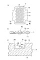
- 2 (a) is a plan view showing the conductor crimping part 111 in an unfolded state
- FIG. 2 (b) is a sectional view taken along the arrow IIb-IIb in FIG. 2 (a)
- FIG. 2 (c) is a sectional view in FIG. It is an enlarged view of the IIc part.
- the cross-sectional shape of the groove-shaped serration 120 is rectangular or inverted trapezoidal, and the inner bottom surface 120A is formed substantially parallel to the outer surface 111S of the conductor crimping portion 111.
- the inner corner portion 120C where the inner side surface 120B and the inner bottom surface 120A intersect is formed as an angular portion where the plane and the plane intersect.
- a hole edge 120D where the inner side surface 120B and the inner surface 111R of the conductor crimping part 111 intersect is formed as an edge.
- the conductor crimping part 111 having such a serration 120 generally has a mold 200 having a convex part 220 at a position corresponding to the concave groove-shaped serration 120 (this is actually Is produced by press working using a serration piece assembled to the upper die of the press die.
- the mold 200 in this case is manufactured by grinding the upper surface of the block 210 using a rotating grindstone because the convex portion 220 has a linear shape.
- FIG. 5 shows the appearance of the mold 200.
- the crimp terminal 101 In order to crimp the conductor crimping portion 111 of the crimp terminal 101 configured as described above to the conductor at the end of the electric wire, the crimp terminal 101 is placed on a mounting surface (upper surface) of a lower mold (anvil) (not shown) Is inserted between the conductor crimping pieces 111A of the conductor crimping part 111 and placed on the upper surface of the bottom plate 111A. Then, by lowering the upper mold (crimper) relative to the lower mold, the leading end side of the conductor crimping piece 111B is gradually tilted inward on the upper mold guide slope.
- the tip of the conductor crimping piece 111B is formed with a curved surface extending from the guide slope of the upper mold to the central chevron.
- the conductor crimping piece 111B is crimped so as to wrap the conductor by rolling it back to the conductor side and biting into the conductor while rubbing the tips of the conductor crimping pieces 111B.
- the conductor crimping portion 111 of the crimp terminal 101 can be connected to the conductor of the electric wire by crimping.
- the covering crimping portion 112 is bent gradually inward using the lower die and the upper die, and the covering crimping piece 112B is crimped to the portion of the electric wire with the insulation coating. By doing so, the crimp terminal 101 can be electrically and mechanically connected to the electric wire.
- the conductor of the electric wire enters into the serration 120 on the inner surface of the conductor crimping portion 111 while being plastically deformed, thereby strengthening the bonding between the crimping terminal 101 and the electric wire. Is done.
- the groove 111 is provided on the inner surface 111R of the conductor crimping portion 111 so as to be orthogonal to the direction in which the electric wire extends, but sufficient contact conductivity is not always obtained. There was a thing.
- the radius of the front edge of the convex part 220 of the press metal mold 200 tends to be small, and as shown in FIGS. 2 (b) and 2 (c),
- the inner corner 120C where the inner bottom surface 120A and the inner side surface 120B of the serration 120 of a certain crimping terminal 101 intersect is squared, and the conductor that has entered the serration 120 is crimped to the conductor of the electric wire.
- the gap is likely to occur in the inner corner 120C. Therefore, when a large gap is generated between the inner corner 120C and the conductor of the electric wire, an oxide film grows from the gap as a starting point due to the effects of thermal shock, mechanical vibration, etc. There is a possibility that the contact conductivity between the terminal 101 and the terminal 101 is lowered.
- the outer peripheral edge of the rotating grindstone cannot be sharpened to prevent chipping, or the corners are gradually removed due to wear.
- the radius of the root of the portion 220 is increased, and as a result, the radius of the hole edge 120D of the serration 120 of the crimp terminal 101 which is a work tends to be increased.
- the radius of the hole edge 120D is increased, problems are likely to occur in the state after the press bonding.
- the hole edge 120D of the serration 120 presses the conductor to be deformed in the front-rear direction so that the conductor does not move in the front-rear direction, whereby the conductor flowing in the serration 120 or outside the serration 120 in the front-rear direction It promotes the rubbing between the conductor and the terminal that extends to improve the peelability of the oxide film.
- the radius of the hole edge 120D is increased, its function is slowed down, and the conductor becomes easy to move when it is desired to receive thermal shock or mechanical vibration. As a result, the contact resistance between the terminal and the conductor increases. .
- An object of the present invention is to provide a crimp terminal capable of constantly maintaining high contact conductivity between a conductor and a terminal.
- the first aspect of the present invention is an electrical connection portion provided at a front portion in a terminal longitudinal direction and a conductor crimp portion provided at a rear portion of the electrical connection portion and connected by being crimped to a conductor of a terminal of an electric wire. And formed in a U-shaped cross section by a bottom plate and a pair of conductor crimping pieces that extend upward from left and right side edges of the bottom plate and are crimped so as to wrap the conductor disposed on the inner surface of the bottom plate.
- a conductor crimping portion wherein the conductor crimping portion is in a state of being separated from each other on the inner surface of the conductor crimping portion before being crimped to the conductor of the terminal of the electric wire.
- Each recess has serrations, and each recess is formed by pressing the conductor pressure-bonding portion using a die having a protrusion formed at a position corresponding to each recess by electric discharge machining.
- the conductor of the electric wire enters into each small circular recess provided as serration on the inner surface of the crimping portion of the conductor while being plastically deformed.
- the bonding between the terminal and the conductor is strengthened.
- the surface of the conductor flowing due to the pressing force rubs against the hole edge of each recess, or the surface of the conductor that enters the recess and the inner surface of the recess rub against each other, thereby oxidizing the surface of the conductor.
- the film is peeled off, and the exposed new surface comes into contact with the terminal.
- this crimp terminal is provided with a large number of small circular recesses, so that the total length of the hole edges of the recesses is effective for scraping the oxide film regardless of the direction of conductor extension. Demonstrate. Therefore, the contact conduction effect due to the exposure of the new surface can be enhanced as compared with the case where a linear serration that intersects the extending direction of the conductor of the electric wire is provided as in the related example.
- the crimp terminal of the present invention is formed by pressing a conductor crimping portion using a die in which a plurality of small circular recesses provided as serrations are formed at positions corresponding to the recesses by electric discharge machining. Therefore, the following merits can be obtained.
- a die having a convex portion at a position corresponding to each round hole by subjecting the base metal block of the die to electric discharge machining using an electrode having a drilled round hole at a position corresponding to the convex portion of the press mold. Can be produced. Then, by pressing the conductor crimping portion using this mold, a crimp terminal having a serrated concave portion having a convex portion transferred to the inner surface of the conductor crimping portion can be obtained.
- the tip peripheral edge of each convex portion of the mold produced by electric discharge machining is naturally processed into a rounded shape due to the characteristics of electric discharge machining.
- the base outer periphery of each convex part of the mold produced by electric discharge machining is machined into a shape with a small radius corresponding to the hole edge of the round hole.
- the hole edge of the small circular concave portion of the conductor crimping portion to which the convex portion of the mold is transferred is processed into a small rounded shape corresponding to the base outer periphery of the convex portion, and the inner peripheral corner of the small circular concave portion is processed.
- the part is processed into a rounded shape corresponding to the peripheral edge of the convex portion.
- the conductor that has entered the small circular recess smoothly flows along the larger radius at the inner peripheral corner of the recess, reducing the gap generated at the inner peripheral corner. Can be made.
- the gap is large, there is a possibility that the oxide film grows from the gap due to the influence of thermal shock or mechanical vibration, and the contact continuity between the conductor and the terminal may be reduced. By reducing the gap, the growth of the oxide film can be suppressed, and good contact conduction performance can be maintained for a long time.
- the contact pressure to the conductor due to the hole edge is increased during crimping, and the longitudinal direction
- the force to hold down the conductor to be deformed is increased, the friction between the conductor flowing in the recess and the conductor extending in the front-rear direction outside the recess and the terminal can be promoted, and the peelability of the oxide film is improved.
- Can play a role As a result, an increase in contact resistance when subjected to thermal shock or mechanical vibration can be suppressed, and stable conduction performance can be maintained.
- the convex part is less likely to be chipped and the durability of the mold is improved.
- the convex part of the mold is formed by grinding, the radius of the tip peripheral edge of the convex part becomes small, but when the convex part of the mold is formed by electric discharge machining, the round of the peripheral edge of the convex part is ground. Will be bigger. This can prevent chipping of the convex portion of the mold (flying chipped fragments).
- the conductor crimping part of the terminal is processed using a press die produced by electric discharge machining, the surface roughness of the inner surface of the conductor crimping part can be increased, and the frictional force between the terminal and the conductor is increased, An increase in contact resistance can be suppressed.
- the second aspect of the present invention is an electrical connection portion provided at a front portion in a terminal longitudinal direction and a conductor crimp portion provided at a rear portion of the electrical connection portion and connected by crimping to a conductor of a terminal of an electric wire. And formed in a U-shaped cross section by a bottom plate and a pair of conductor crimping pieces that extend upward from left and right side edges of the bottom plate and are crimped so as to wrap the conductor disposed on the inner surface of the bottom plate.
- a conductor crimping portion wherein the conductor crimping portion is in a state of being separated from each other on the inner surface of the conductor crimping portion before being crimped to the conductor of the terminal of the electric wire.
- Recesses are provided as serrations, and each of the recesses is press-worked using a die in which a protrusion is formed at a position corresponding to each recess by press-fitting a pin into a press-fitting hole formed in the block.
- Each recess is formed by Crimping having an inner peripheral corner portion with a radius corresponding to the chamfered portion of the peripheral edge of the pin and a hole edge formed with a standing edge corresponding to the chamfered portion provided at the hole edge of the press-fitting hole
- the gist is that it is a terminal.
- this crimp terminal When this crimp terminal is used to crimp the conductor crimping part to the conductor of the electric wire, the conductor of the electric wire enters the small circular recesses provided as serrations on the inner surface of the conductor crimping part while plastically deforming.
- the bonding between the terminal and the conductor is strengthened.
- the surface of the conductor flowing due to the pressing force rubs against the hole edge of each recess, or the surface of the conductor that enters the recess and the inner surface of the recess rub against each other, thereby oxidizing the surface of the conductor.
- the film is peeled off, and the exposed new surface comes into contact with the terminal.
- this crimp terminal is provided with a large number of small circular recesses, so that the total length of the hole edges of the recesses is effective for scraping the oxide film regardless of the direction of conductor extension. Demonstrate. Therefore, the contact conduction effect due to the exposure of the new surface can be enhanced as compared with the case where a linear serration that intersects the extending direction of the conductor of the electric wire is provided as in the related example.
- a linear concave part is formed in the base metal bracket of the mold.
- the protrusions of the mold are formed into cylindrical pins in circular press-fitting holes formed in the base material block. Can be made easily by press-fitting.
- the crimp terminal of the present invention presses a conductor crimping portion using a mold in which a large number of small circular recesses provided as serrations press-fit a pin into a press-fitting hole formed in a block. Therefore, the following merits can be obtained.
- a mold having a convex part can be manufactured easily. Then, by pressing the conductor crimping portion using this mold, a crimp terminal having a serrated concave portion having a convex portion transferred to the inner surface of the conductor crimping portion can be obtained.
- a large chamfered portion is provided at the periphery of the tip of the pin, and a chamfered portion of an appropriate size is provided at the edge of the press-fitting hole corresponding to the base of the convex portion, thereby reducing the size of the conductor crimping portion.
- the radius transferred by the chamfered portion at the peripheral edge of the tip of the pin can be formed at the inner peripheral corner of the circular concave portion, and transferred by the chamfered portion of the hole edge of the press-fitting hole to the hole edge of the small circular concave portion. Raised standing edges can be formed.
- the conductor that has entered the small circular recess smoothly flows along the larger radius at the inner peripheral corner of the recess, reducing the gap generated at the inner peripheral corner. Can be made.
- the gap is large, there is a possibility that the oxide film grows from the gap due to the influence of thermal shock or mechanical vibration, and the contact continuity between the conductor and the terminal may be reduced. By reducing the gap, the growth of the oxide film can be suppressed, and good contact conduction performance can be maintained for a long time.
- the rising edge bites into the conductor during crimping, and that part becomes the starting point of the elongation of the conductor that is deformed in the front-rear direction.
- the function of improving the peelability of the oxide film on the conductor surface can be achieved.
- an increase in contact resistance when subjected to thermal shock or mechanical vibration can be suppressed, and stable conduction performance can be maintained.
- the convex portion is less likely to be chipped, and the durability of the die is improved.
- the convex part of the mold is formed by grinding, the radius of the peripheral edge of the convex part becomes small, but when the convex part of the mold is formed by press-fitting a pin, the chamfered shape of the peripheral edge of the convex part Can be set large freely. This can prevent chipping of the convex portion of the mold (flying chipped fragments) and improve the durability of the mold.
- FIG. 1 is a perspective view showing a configuration of a related crimp terminal.
- 2 is a diagram showing a state before crimping of a conductor crimping portion of the crimping terminal of FIG. 1, (a) is a developed plan view, (b) is a sectional view taken along the arrow IIb-IIb in (a), and (c).
- FIG. 4 is an enlarged view of a portion IIc in (b).
- FIG. 3 is a cross-sectional view showing a state where the serration of the crimp terminal in FIG. 1 is being pressed.
- FIG. 4 is a side view showing a state where convex portions for serration are formed by grinding on the press mold used in the press working of FIG. FIG.
- FIG. 5 is an external perspective view of a press die produced through the processing of FIG.
- FIG. 6 is a perspective view showing the configuration of the crimp terminal according to the embodiment of the present invention.
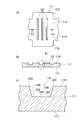
- 7 is a diagram showing a state before crimping of the conductor crimping portion of the crimping terminal of FIG. 6, (a) is a developed plan view, (b) is a sectional view taken along arrow VIIb-VIIb in (a), (c).
- FIG. 4 is an enlarged view of a VIIc portion of (b).
- FIG. 8 is a side cross-sectional view for explaining the content of forming a small circular concave portion of the conductor crimping portion of the crimping terminal of FIG. 6 by a press die having a convex portion.
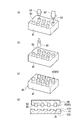
- FIG. 9 is an explanatory view of the process until the crimp terminal according to the first embodiment of the present invention is formed.
- FIGS. 9A to 9D show a press die produced by electric discharge machining, and the press die is used. It is explanatory drawing which shows the content until it press-molds the said conductor crimping
- FIG. 10 is an enlarged cross-sectional view showing the relationship between the convex portion of the mold and the small circular concave portion of the conductor crimping portion during press molding.
- FIGS. 11A to 11D are enlarged cross-sectional views schematically showing the state in which the conductor enters the small circular recess of the conductor crimping portion while being plastically deformed during crimping.
- FIGS. 12A and 12B are explanatory diagrams of processes up to the formation of the crimp terminal according to the second embodiment of the present invention.
- FIGS. 12A to 12D show a press mold by press-fitting a pin into a base material block. It is explanatory drawing which shows the content until it press-molds the said conductor crimping
- 13A is a cross-sectional view showing the relationship between the base material block and the press-fitted pin
- FIG. 13B is a partially enlarged cross-sectional view thereof.
- FIG. 14 is a sectional view of a small circular recess formed by pressing a conductor crimping portion using the same mold.
- FIG. 15 is a schematic cross-sectional view showing a state when the conductor is pressed against the concave portion formed as shown in FIG. 14 during crimping.
- FIG. 6 is a perspective view showing the configuration of the crimp terminal of the embodiment
- FIG. 7 is a diagram showing a state before crimping of the conductor crimping portion of the crimp terminal
- FIG. 7A is a developed plan view
- FIG. FIG. 7A is a cross-sectional view taken along the line VIIb-VIIb in FIG. 7A
- FIG. 7C is an enlarged view of a portion VIIc in FIG. 7B.
- the crimp terminal 1 is of a female type, and has a male terminal on the mating connector side at the front in the longitudinal direction of the terminal (which is also the longitudinal direction of the conductor of the electric wire to be connected, that is, the direction in which the electric wire extends).
- a coating caulking portion 12 that is caulked to a portion of the electric wire with an insulating coating.
- connection part 14 Between the electrical connection part 10 and the conductor crimping
- the conductor crimping portion 11 includes a bottom plate 11A and a pair of conductor crimping pieces 11B and 11B that are extended from the left and right side edges of the bottom plate 11A and are crimped so as to wrap the conductors of the electric wires disposed on the inner surface of the bottom plate 11A.
- the cover crimping portion 12 is a pair of crimps so as to wrap the bottom plate 12A and electric wires (parts with an insulation coating) that extend upward from the left and right side edges of the bottom plate 12A and are arranged on the inner surface of the bottom plate 12A.
- the covering crimping pieces 12B and 12B are formed in a substantially U-shaped cross section.
- the first connecting portion 13 and the second connecting portion 14 before and after the conductor crimping portion 11 are both bottom plates 13A and 14A, and low-profile side plates 13B and 14B that stand upward from the left and right edges of the bottom plates 13A and 14A. And a U-shaped cross section.
- the bottom plate (the bottom plate 13A of the first connecting portion 13, the bottom plate 11A of the conductor crimping portion 11, the second connecting portion) in the range from the bottom plate (not shown) of the front electrical connecting portion 10 to the last cover crimping portion 12.
- the bottom plate 14A of the portion 14 and the bottom plate 12A of the cover crimping portion 12 are continuously formed in a single strip shape.
- the front and rear ends of the low-profile side plate 13B of the first connecting portion 13 are respectively connected to the lower half of the rear end of the side plate (reference numeral omitted) of the electrical connecting portion 10 and the front end of the conductor crimping piece 11B of the conductor crimping portion 11.
- the front and rear ends of the low-side side plate 14B of the second connecting portion 14 are respectively below the rear end of the conductor crimping piece 11B of the conductor crimping portion 11 and the front end of the covering crimping piece 12B of the covering crimping portion 12. Each half is continuous.
- the inner surface 11R on the side in contact with the conductor of the electric wire among the inner surface 11R and the outer surface 11S of the conductor crimping portion 11 has a large number of small serrations as concave serrations.
- the circular recesses 20 are provided so as to be scattered in a staggered manner in a state of being separated from each other.
- each small circular recess 20 is rectangular or inverted trapezoidal, and the inner bottom surface 20 ⁇ / b> A of the recess 20 is formed substantially parallel to the outer surface 11 ⁇ / b> S of the conductor crimping portion 11. Yes.
- the inner peripheral corner 20C where the inner side surface 20B of the recess 20 and the inner bottom surface 20A intersect is provided with a radius that connects the inner bottom surface 20A and the inner peripheral side surface 20B with a smooth continuous curved surface.
- the serration (small circular recess 20) of the conductor crimping portion 11 is pressed with dies 70 and 80 having a large number of cylindrical convex portions 72 and 85 corresponding to the recess 20.
- the radius of the inner peripheral corner 20C of the recess 20 of the serration is processed by attaching a radius to the peripheral edges of the cylindrical projections 72, 85 of the molds 70, 80. Yes.
- the press die 70 used in the first embodiment is made by electric discharge machining.
- a circular recess 52 (round hole) for making a cylindrical protrusion 72 of the mold is formed on the upper surface of the base material block 51 as a drill 60.
- FIG.9 (b) by using the electrode 50 which has many drilled recessed parts 52, by performing electric discharge machining on the base metal block 71 of the mold as a work, and melting the unnecessary part, As shown in FIG. 9C, a press die 70 having a large number of cylindrical protrusions 72 is made.
- the radius is transferred to the inner peripheral corner 20 ⁇ / b> C of the small circular recess 20.
- a small radius can be transferred to the hole edge 20D of the small circular recess 20.
- the crimp terminal 1 In order to crimp the conductor crimping portion 11 of the crimp terminal 1 to the conductor at the end of the electric wire, the crimp terminal 1 is placed on the mounting surface (upper surface) of the lower mold (anvil) (not shown), and the conductor at the end of the electric wire is attached. It is inserted between the conductor crimping pieces 11A of the conductor crimping part 11 and placed on the upper surface (inner surface 11R) of the bottom plate 11A. Then, by lowering the upper mold (crimper) relative to the lower mold, the tip side of the conductor crimping piece 11B is gradually tilted inward on the upper mold guide slope.
- the tip of the conductor crimping piece 11B is formed with a curved surface that continues from the guide slope of the upper mold to the central chevron.
- the conductor crimping piece 11B is crimped so as to enclose the conductor by rolling it back to the conductor side and biting into the conductor while rubbing the tips of the conductor crimping pieces 11B.
- the conductor crimping portion 11 of the crimp terminal 1 can be connected to the conductor of the electric wire by crimping.
- the covering crimping portion 12 is gradually bent inward using the lower mold and the upper mold, and the covering crimping piece 12B is crimped to the portion of the electric wire with the insulation coating. By doing so, the crimp terminal 1 can be electrically and mechanically connected to the electric wire.
- the conductor of the electric wire is plastically deformed in each small circular recess 20 provided as a serration on the inner surface 11R of the conductor crimp part 11.
- the connection between the terminal and the conductor is strengthened by entering.
- the surface of the conductor flowing due to the pressing force and the hole edge 20D of each recess 20 rub against each other, or the surface of the conductor entering the recess 20 and the inner side surface 20B of the recess 20 rub against each other,
- the oxide film on the surface of the conductor is peeled off, and the exposed new surface is brought into contact with the terminal.
- the protrusions 72 of the press mold 70 can be easily formed by electric discharge machining. . That is, a large number of small circular convex portions 72 can be transferred to the press die 70 simply by drilling a large number of small circular concave portions 52 as round holes in the base material block 51 of the electrode 50.
- the crimp terminal 1 of this embodiment uses a press die 70 in which a large number of small circular concave portions 20 provided as serrations have convex portions 72 formed at positions corresponding to the concave portions 20 by electric discharge machining. Since the conductor crimping portion 11 is formed by pressing, the following merits can be obtained.
- each convex portion 72 of the press die 70 manufactured by electric discharge machining is naturally processed into a rounded shape due to the characteristics of electric discharge machining.
- the base outer periphery 72D of each convex portion 72 of the press die 70 produced by electric discharge machining is processed into a shape with a small radius corresponding to the hole edge of the round hole (circular concave portion 52).
- the hole edge 20D of the small circular concave portion 20 of the conductor crimping portion 11 to which the convex portion 72 of the press mold 70 has been transferred is processed into a shape with a small radius corresponding to the root outer periphery 72D of the convex portion 72,
- the inner peripheral corner 20C of the small circular recess 20 is processed into a rounded shape corresponding to the tip peripheral edge 72C of the convex 72.
- the conductor Wa that has entered the small circular recess 20 smoothly follows the radius of the inner peripheral corner 20C of the recess 20.
- the gap generated at the inner peripheral corner 20C can be reduced.
- the oxide film grows from the gap due to the influence of thermal shock or mechanical vibration, and the contact continuity between the conductor and the terminal may be reduced.
- the gap By reducing the gap, the growth of the oxide film can be suppressed, and good contact conduction performance can be maintained for a long time.
- the hole edge 20D of the small circular recess 20 is processed into a small rounded shape corresponding to the root outer periphery 72D of the convex part 72 of the press die 70, the hole edge 20D is applied to the conductor Wa at the time of crimping.
- the contact pressure is increased, the force for pressing the conductor Wa to be deformed in the front-rear direction is increased, and the friction between the conductor Wa flowing in the recess and the conductor Wa extending in the front-rear direction outside the recess 20 and the terminal 1 is increased. It can be promoted and can serve to improve the peelability of the oxide film. As a result, an increase in contact resistance when subjected to thermal shock or mechanical vibration can be suppressed, and stable conduction performance can be maintained.
- the convex portion 72 is less likely to be chipped, and the durability of the press die 70 is improved.
- the convex portion of the mold is formed by grinding, it is necessary to form the rounded edge of the tip of the convex portion in a separate process, but when the convex portion 72 of the press die 70 is formed by electric discharge machining, The radius of the distal edge 72C of the portion 72 can be processed simultaneously.
- the conductor crimping portion 11 of the terminal 1 is processed using the press die 70 produced by electric discharge machining, the surface roughness of the inner surface of the conductor crimping portion 11 can be increased, and the friction between the terminal 1 and the conductor Wa is achieved. An increase in contact resistance can be suppressed by increasing the force.
- the crimp terminal 1 may be molded using a mold having another structure. it can.
- the conductor crimping portion 11 of the crimping terminal 1 shown in FIG. 12 a large number of small circular recesses 20 provided as serrations press fit the lower half of the pin 83 into the press-fitting holes 82 formed in the base material block 81.
- the conductor crimping portion 11 is formed by pressing using a mold 80 in which a convex portion 85 is formed at a position corresponding to the concave portion 20.
- the used press die 80 is formed by drilling a circular press-fitting hole 82 having a predetermined depth with a drill 61 on the upper surface of the base metal block 81 of the die.
- the lower half of the cylindrical pin 83 is press-fitted into the press-fitting holes 82, so that a convex made up of a large number of pins 83 as shown in FIG. A press die 80 having a portion 85 is produced.
- chamfering is performed on the hole edge 82 ⁇ / b> D of the press-fitting hole 82, and chamfering is performed on the tip peripheral edge 83 ⁇ / b> C of the pin 83.
- a larger round (or larger) is formed at the inner peripheral corner portion 20 ⁇ / b> C of the small circular recess 20.
- Chamfering can be transferred, and the standing edge 20E can be transferred to the hole edge 20D of the small circular recess 20.
- the crimping terminal 1 is placed on the mounting surface (upper surface) of the lower mold (anvil) (not shown) and the end of the electric wire Is inserted between the conductor crimping pieces 11A of the conductor crimping portion 11 and placed on the upper surface (inner surface 11R) of the bottom plate 11A. Then, by lowering the upper mold (crimper) relative to the lower mold, the tip side of the conductor crimping piece 11B is gradually tilted inward on the upper mold guide slope.
- the tip of the conductor crimping piece 11B is formed with a curved surface that continues from the guide slope of the upper mold to the central chevron.
- the conductor crimping piece 11B is crimped so as to enclose the conductor by rolling it back to the conductor side and biting into the conductor while rubbing the tips of the conductor crimping pieces 11B.
- the conductor crimping portion 11 of the crimp terminal 1 can be connected to the conductor of the electric wire by crimping.
- the covering crimping portion 12 is gradually bent inward using the lower mold and the upper mold, and the covering crimping piece 12B is crimped to the portion of the electric wire with the insulation coating. By doing so, the crimp terminal 1 can be electrically and mechanically connected to the electric wire.
- a large chamfered portion is provided at the tip peripheral edge 83 ⁇ / b> C of the pin 83, and a chamfered portion of an appropriate size is provided at the hole edge 82 ⁇ / b> D of the press-fitting hole 82 corresponding to the root of the convex portion 85.
- a rounded portion or chamfered portion
- the standing edge 20E transferred by the chamfered portion of the hole edge 82D of the press-fitting hole 82 can be formed on the hole edge 20D of the small circular recess 20.
- the conductor Wa that has entered the small circular recess 20 smoothly flows along the radius of the inner peripheral corner 20C of the recess 20, A gap generated in the inner peripheral corner 20C can be reduced.
- the gap is large, there is a possibility that the oxide film grows from the gap due to the influence of thermal shock or mechanical vibration, and the contact conductivity between the conductor Wa and the terminal is lowered.
- the gap can be reduced, the growth of the oxide film can be suppressed, and good contact conduction performance can be maintained for a long time.
- the rising edge 20E bites into the conductor Wa at the time of crimping, and the portion of the conductor Wa to be deformed in the front-rear direction. It becomes a starting point of elongation, and can thereby serve to improve the peelability of the oxide film on the surface of the conductor Wa. As a result, it is possible to suppress an increase in contact resistance when it is desired to receive thermal shock or mechanical vibration, and it is possible to maintain stable conduction performance.
- the convex portion 85 By forming the convex portion 85 by the completely circular pin 83 in the press die 80, the convex portion 85 is less likely to be chipped, and the durability of the die 80 is improved.
- the convex part of the mold is formed by grinding, the radius of the peripheral edge of the convex part is reduced.
- the convex part 85 of the press mold 80 is formed by press-fitting the pin 83, the tip of the convex part 85 is formed.
- the chamfered shape of the peripheral edge 83C can be set freely. As a result, chipping of the convex portion 85 of the press die 80 can be prevented, and the durability of the press die 80 can be improved.
- the crimp terminal 1 is a female terminal fitting having a box-shaped electrical connection portion 10, but is not limited thereto, and may be a male terminal fitting having a male tab, or a metal plate material having a through hole.
- a so-called LA terminal may be formed, and a crimp terminal having an arbitrary shape may be used as necessary.
Landscapes
- Engineering & Computer Science (AREA)
- Mechanical Engineering (AREA)
- Connections Effected By Soldering, Adhesion, Or Permanent Deformation (AREA)
Abstract
Description
Claims (2)
- 端子長手方向の前部に設けられた電気接続部と、
前記電気接続部の後部に設けられ、電線の端末の導体に圧着して接続される導体圧着部であって、底板と前記底板の左右両側縁から上方に延設されて前記底板の内面上に配された前記導体を包むように加締められる一対の導体加締片とで断面U字状に形成された導体圧着部と、を備え、
前記導体圧着部は、前記電線の端末の導体に圧着される前の状態において、前記導体圧着部の内面に、互いに離間した状態で点在する複数の円形の凹部をセレーションとして有し、
前記各凹部は、放電加工により前記各凹部に対応する位置に凸部を形成した金型を用いて前記導体圧着部をプレス加工することにより形成され、
前記各凹部は、前記金型の前記凸部の根元外周に対応したアールの付いた内周隅部と、前記金型の前記凸部の先端周縁に対応したアールの付いた孔縁とを有する
圧着端子。 - 端子長手方向の前部に設けられた電気接続部と、
前記電気接続部の後部に設けられ、電線の端末の導体に圧着して接続される導体圧着部であって、底板と前記底板の左右両側縁から上方に延設されて前記底板の内面上に配された前記導体を包むように加締められる一対の導体加締片とで断面U字状に形成された導体圧着部と、を備え、
前記導体圧着部は、前記電線の端末の導体に圧着される前の状態において、前記導体圧着部の内面に、互いに離間した状態で点在する複数の円形の凹部をセレーションとして有し、
前記各凹部は、ブロックに形成した圧入穴にピンを圧入することで前記各凹部に対応する位置に凸部を形成した金型を用いて前記導体圧着部をプレス加工することにより形成され、
前記各凹部は、前記ピンの先端周縁の面取部に対応したアールの付いた内周隅部と、前記圧入穴の孔縁に設けられた面取部に対応した起立エッジが形成された孔縁とを有する
圧着端子。
Priority Applications (2)
| Application Number | Priority Date | Filing Date | Title |
|---|---|---|---|
| CN201180038636.XA CN103069666B (zh) | 2010-08-05 | 2011-07-14 | 压接端子 |
| US13/814,159 US8814612B2 (en) | 2010-08-05 | 2011-07-14 | Crimp terminal |
Applications Claiming Priority (2)
| Application Number | Priority Date | Filing Date | Title |
|---|---|---|---|
| JP2010176036A JP5634788B2 (ja) | 2010-08-05 | 2010-08-05 | 圧着端子 |
| JP2010-176036 | 2010-08-05 |
Publications (1)
| Publication Number | Publication Date |
|---|---|
| WO2012017802A1 true WO2012017802A1 (ja) | 2012-02-09 |
Family
ID=45559309
Family Applications (1)
| Application Number | Title | Priority Date | Filing Date |
|---|---|---|---|
| PCT/JP2011/066112 Ceased WO2012017802A1 (ja) | 2010-08-05 | 2011-07-14 | 圧着端子 |
Country Status (4)
| Country | Link |
|---|---|
| US (1) | US8814612B2 (ja) |
| JP (1) | JP5634788B2 (ja) |
| CN (1) | CN103069666B (ja) |
| WO (1) | WO2012017802A1 (ja) |
Cited By (1)
| Publication number | Priority date | Publication date | Assignee | Title |
|---|---|---|---|---|
| JP2014046322A (ja) * | 2012-08-30 | 2014-03-17 | Daihatsu Motor Co Ltd | 溝付きプレートの製造方法 |
Families Citing this family (10)
| Publication number | Priority date | Publication date | Assignee | Title |
|---|---|---|---|---|
| JP5890992B2 (ja) * | 2011-10-05 | 2016-03-22 | 矢崎総業株式会社 | 圧着端子 |
| JP5909345B2 (ja) * | 2011-11-11 | 2016-04-26 | 矢崎総業株式会社 | コネクタ端子 |
| JP5992231B2 (ja) * | 2012-07-02 | 2016-09-14 | 矢崎総業株式会社 | 電線と端子との圧着構造 |
| JP6563168B2 (ja) * | 2013-11-25 | 2019-08-21 | 矢崎総業株式会社 | 圧着端子 |
| US10128581B2 (en) * | 2014-06-19 | 2018-11-13 | Fujikura Ltd. | Crimp terminal |
| JP6463446B1 (ja) * | 2017-11-16 | 2019-02-06 | イリソ電子工業株式会社 | 可動コネクタ |
| JP6440277B1 (ja) * | 2017-11-24 | 2018-12-19 | 株式会社白山 | 圧着接続部材の製造方法 |
| JP6537151B1 (ja) | 2018-05-31 | 2019-07-03 | 株式会社関プレス | 突起部形成方法、突起部形成システム、及び突起部を有する金属部品の製造方法 |
| CN112496205A (zh) * | 2020-11-27 | 2021-03-16 | 贵州航天精工制造有限公司 | 一种电线端子定位检查结构加工装置及其加工方法 |
| CN113161046A (zh) * | 2021-04-02 | 2021-07-23 | 云锦人工智能科技集团有限公司 | 一种桥接模块 |
Citations (4)
| Publication number | Priority date | Publication date | Assignee | Title |
|---|---|---|---|---|
| JPH05152011A (ja) * | 1991-11-26 | 1993-06-18 | Sumitomo Wiring Syst Ltd | 圧着端子 |
| JP2008305571A (ja) * | 2007-06-05 | 2008-12-18 | Norio Kato | 圧着端子および圧着端子の製造方法 |
| JP2009245695A (ja) * | 2008-03-31 | 2009-10-22 | Furukawa Electric Co Ltd:The | 圧着端子 |
| JP2010027463A (ja) * | 2008-07-22 | 2010-02-04 | Sumitomo Wiring Syst Ltd | 端子金具および端子金具付き電線 |
Family Cites Families (3)
| Publication number | Priority date | Publication date | Assignee | Title |
|---|---|---|---|---|
| JP5058082B2 (ja) * | 2008-06-18 | 2012-10-24 | 株式会社オートネットワーク技術研究所 | 端子金具及び端子付き電線 |
| JP5311962B2 (ja) * | 2008-10-24 | 2013-10-09 | 矢崎総業株式会社 | アルミ電線用圧着端子及びアルミ電線用圧着端子の製造方法 |
| US8485853B2 (en) * | 2011-11-03 | 2013-07-16 | Delphi Technologies, Inc. | Electrical contact having knurl pattern with recessed rhombic elements that each have an axial minor distance |
-
2010
- 2010-08-05 JP JP2010176036A patent/JP5634788B2/ja not_active Expired - Fee Related
-
2011
- 2011-07-14 CN CN201180038636.XA patent/CN103069666B/zh not_active Expired - Fee Related
- 2011-07-14 US US13/814,159 patent/US8814612B2/en active Active
- 2011-07-14 WO PCT/JP2011/066112 patent/WO2012017802A1/ja not_active Ceased
Patent Citations (4)
| Publication number | Priority date | Publication date | Assignee | Title |
|---|---|---|---|---|
| JPH05152011A (ja) * | 1991-11-26 | 1993-06-18 | Sumitomo Wiring Syst Ltd | 圧着端子 |
| JP2008305571A (ja) * | 2007-06-05 | 2008-12-18 | Norio Kato | 圧着端子および圧着端子の製造方法 |
| JP2009245695A (ja) * | 2008-03-31 | 2009-10-22 | Furukawa Electric Co Ltd:The | 圧着端子 |
| JP2010027463A (ja) * | 2008-07-22 | 2010-02-04 | Sumitomo Wiring Syst Ltd | 端子金具および端子金具付き電線 |
Cited By (1)
| Publication number | Priority date | Publication date | Assignee | Title |
|---|---|---|---|---|
| JP2014046322A (ja) * | 2012-08-30 | 2014-03-17 | Daihatsu Motor Co Ltd | 溝付きプレートの製造方法 |
Also Published As
| Publication number | Publication date |
|---|---|
| JP2012038487A (ja) | 2012-02-23 |
| US8814612B2 (en) | 2014-08-26 |
| CN103069666A (zh) | 2013-04-24 |
| US20130137315A1 (en) | 2013-05-30 |
| CN103069666B (zh) | 2015-05-27 |
| JP5634788B2 (ja) | 2014-12-03 |
Similar Documents
| Publication | Publication Date | Title |
|---|---|---|
| JP5634788B2 (ja) | 圧着端子 | |
| JP5601926B2 (ja) | 圧着端子 | |
| JP4922897B2 (ja) | 圧着端子、端子付電線及びその製造方法 | |
| EP2290748A1 (en) | Terminal fitting and cable provided with terminal | |
| WO2012018050A1 (ja) | 圧着端子 | |
| JP5519382B2 (ja) | 圧着端子及びその製造方法 | |
| JP5074984B2 (ja) | 圧着端子 | |
| JP5886517B2 (ja) | 圧着端子 | |
| JP5634789B2 (ja) | 圧着端子 | |
| US6890222B2 (en) | Electrical connection | |
| JP5601925B2 (ja) | 圧着端子 | |
| JP4894734B2 (ja) | 端子金具 | |
| WO2013110503A1 (en) | Electrical contact terminal comprising a crimping section | |
| JP3542712B2 (ja) | 圧接端子 | |
| EP2187478A1 (en) | A terminal fitting, a wire connection structure and a connecting method | |
| JP7477268B2 (ja) | 圧着端子 | |
| JP6933536B2 (ja) | 電線付端子 | |
| JP2019057392A (ja) | 圧着端子、電線付端子、およびその製造方法 | |
| JP2023061220A (ja) | 圧着端子 | |
| WO2015068648A1 (ja) | 圧着端子 | |
| JP2011103264A (ja) | 圧着端子の圧着構造 |
Legal Events
| Date | Code | Title | Description |
|---|---|---|---|
| WWE | Wipo information: entry into national phase |
Ref document number: 201180038636.X Country of ref document: CN |
|
| 121 | Ep: the epo has been informed by wipo that ep was designated in this application |
Ref document number: 11814432 Country of ref document: EP Kind code of ref document: A1 |
|
| WWE | Wipo information: entry into national phase |
Ref document number: 13814159 Country of ref document: US |
|
| NENP | Non-entry into the national phase |
Ref country code: DE |
|
| 122 | Ep: pct application non-entry in european phase |
Ref document number: 11814432 Country of ref document: EP Kind code of ref document: A1 |