WO2012017706A1 - ワイヤハーネス用クリップおよびワイヤハーネス用クリップの車体取付方法 - Google Patents
ワイヤハーネス用クリップおよびワイヤハーネス用クリップの車体取付方法 Download PDFInfo
- Publication number
- WO2012017706A1 WO2012017706A1 PCT/JP2011/057595 JP2011057595W WO2012017706A1 WO 2012017706 A1 WO2012017706 A1 WO 2012017706A1 JP 2011057595 W JP2011057595 W JP 2011057595W WO 2012017706 A1 WO2012017706 A1 WO 2012017706A1
- Authority
- WO
- WIPO (PCT)
- Prior art keywords
- clip
- wire harness
- type
- bracket
- metal clip
- Prior art date
- Legal status (The legal status is an assumption and is not a legal conclusion. Google has not performed a legal analysis and makes no representation as to the accuracy of the status listed.)
- Ceased
Links
Images




Classifications
-
- B—PERFORMING OPERATIONS; TRANSPORTING
- B60—VEHICLES IN GENERAL
- B60R—VEHICLES, VEHICLE FITTINGS, OR VEHICLE PARTS, NOT OTHERWISE PROVIDED FOR
- B60R16/00—Electric or fluid circuits specially adapted for vehicles and not otherwise provided for; Arrangement of elements of electric or fluid circuits specially adapted for vehicles and not otherwise provided for
- B60R16/02—Electric or fluid circuits specially adapted for vehicles and not otherwise provided for; Arrangement of elements of electric or fluid circuits specially adapted for vehicles and not otherwise provided for electric constitutive elements
- B60R16/0207—Wire harnesses
- B60R16/0215—Protecting, fastening and routing means therefor
-
- B—PERFORMING OPERATIONS; TRANSPORTING
- B60—VEHICLES IN GENERAL
- B60R—VEHICLES, VEHICLE FITTINGS, OR VEHICLE PARTS, NOT OTHERWISE PROVIDED FOR
- B60R16/00—Electric or fluid circuits specially adapted for vehicles and not otherwise provided for; Arrangement of elements of electric or fluid circuits specially adapted for vehicles and not otherwise provided for
- B60R16/02—Electric or fluid circuits specially adapted for vehicles and not otherwise provided for; Arrangement of elements of electric or fluid circuits specially adapted for vehicles and not otherwise provided for electric constitutive elements
- B60R16/0207—Wire harnesses
-
- B—PERFORMING OPERATIONS; TRANSPORTING
- B65—CONVEYING; PACKING; STORING; HANDLING THIN OR FILAMENTARY MATERIAL
- B65D—CONTAINERS FOR STORAGE OR TRANSPORT OF ARTICLES OR MATERIALS, e.g. BAGS, BARRELS, BOTTLES, BOXES, CANS, CARTONS, CRATES, DRUMS, JARS, TANKS, HOPPERS, FORWARDING CONTAINERS; ACCESSORIES, CLOSURES, OR FITTINGS THEREFOR; PACKAGING ELEMENTS; PACKAGES
- B65D63/00—Flexible elongated elements, e.g. straps, for bundling or supporting articles
- B65D63/10—Non-metallic straps, tapes, or bands; Filamentary elements, e.g. strings, threads or wires; Joints between ends thereof
- B65D63/1018—Joints produced by application of integral securing members, e.g. buckles, wedges, tongue and slot, locking head and teeth or the like
- B65D63/1027—Joints produced by application of integral securing members, e.g. buckles, wedges, tongue and slot, locking head and teeth or the like the integral securing member being formed as a female and male locking member, e.g. locking head and locking teeth, or the like
- B65D63/1063—Joints produced by application of integral securing members, e.g. buckles, wedges, tongue and slot, locking head and teeth or the like the integral securing member being formed as a female and male locking member, e.g. locking head and locking teeth, or the like the female locking member being provided with at least one plastic barb
-
- F—MECHANICAL ENGINEERING; LIGHTING; HEATING; WEAPONS; BLASTING
- F16—ENGINEERING ELEMENTS AND UNITS; GENERAL MEASURES FOR PRODUCING AND MAINTAINING EFFECTIVE FUNCTIONING OF MACHINES OR INSTALLATIONS; THERMAL INSULATION IN GENERAL
- F16B—DEVICES FOR FASTENING OR SECURING CONSTRUCTIONAL ELEMENTS OR MACHINE PARTS TOGETHER, e.g. NAILS, BOLTS, CIRCLIPS, CLAMPS, CLIPS OR WEDGES; JOINTS OR JOINTING
- F16B2/00—Friction-grip releasable fastenings
- F16B2/02—Clamps, i.e. with gripping action effected by positive means other than the inherent resistance to deformation of the material of the fastening
- F16B2/06—Clamps, i.e. with gripping action effected by positive means other than the inherent resistance to deformation of the material of the fastening external, i.e. with contracting action
- F16B2/08—Clamps, i.e. with gripping action effected by positive means other than the inherent resistance to deformation of the material of the fastening external, i.e. with contracting action using bands
-
- F—MECHANICAL ENGINEERING; LIGHTING; HEATING; WEAPONS; BLASTING
- F16—ENGINEERING ELEMENTS AND UNITS; GENERAL MEASURES FOR PRODUCING AND MAINTAINING EFFECTIVE FUNCTIONING OF MACHINES OR INSTALLATIONS; THERMAL INSULATION IN GENERAL
- F16B—DEVICES FOR FASTENING OR SECURING CONSTRUCTIONAL ELEMENTS OR MACHINE PARTS TOGETHER, e.g. NAILS, BOLTS, CIRCLIPS, CLAMPS, CLIPS OR WEDGES; JOINTS OR JOINTING
- F16B2/00—Friction-grip releasable fastenings
- F16B2/20—Clips, i.e. with gripping action effected solely by the inherent resistance to deformation of the material of the fastening
- F16B2/22—Clips, i.e. with gripping action effected solely by the inherent resistance to deformation of the material of the fastening of resilient material, e.g. rubbery material
-
- F—MECHANICAL ENGINEERING; LIGHTING; HEATING; WEAPONS; BLASTING
- F16—ENGINEERING ELEMENTS AND UNITS; GENERAL MEASURES FOR PRODUCING AND MAINTAINING EFFECTIVE FUNCTIONING OF MACHINES OR INSTALLATIONS; THERMAL INSULATION IN GENERAL
- F16B—DEVICES FOR FASTENING OR SECURING CONSTRUCTIONAL ELEMENTS OR MACHINE PARTS TOGETHER, e.g. NAILS, BOLTS, CIRCLIPS, CLAMPS, CLIPS OR WEDGES; JOINTS OR JOINTING
- F16B2/00—Friction-grip releasable fastenings
- F16B2/20—Clips, i.e. with gripping action effected solely by the inherent resistance to deformation of the material of the fastening
- F16B2/22—Clips, i.e. with gripping action effected solely by the inherent resistance to deformation of the material of the fastening of resilient material, e.g. rubbery material
- F16B2/24—Clips, i.e. with gripping action effected solely by the inherent resistance to deformation of the material of the fastening of resilient material, e.g. rubbery material of metal
-
- F—MECHANICAL ENGINEERING; LIGHTING; HEATING; WEAPONS; BLASTING
- F16—ENGINEERING ELEMENTS AND UNITS; GENERAL MEASURES FOR PRODUCING AND MAINTAINING EFFECTIVE FUNCTIONING OF MACHINES OR INSTALLATIONS; THERMAL INSULATION IN GENERAL
- F16B—DEVICES FOR FASTENING OR SECURING CONSTRUCTIONAL ELEMENTS OR MACHINE PARTS TOGETHER, e.g. NAILS, BOLTS, CIRCLIPS, CLAMPS, CLIPS OR WEDGES; JOINTS OR JOINTING
- F16B5/00—Joining sheets or plates, e.g. panels, to one another or to strips or bars parallel to them
- F16B5/12—Fastening strips or bars to sheets or plates, e.g. rubber strips, decorative strips for motor vehicles, by means of clips
- F16B5/121—Fastening strips or bars to sheets or plates, e.g. rubber strips, decorative strips for motor vehicles, by means of clips fastened over the edge(s) of the sheet(s) or plate(s)
-
- H—ELECTRICITY
- H02—GENERATION; CONVERSION OR DISTRIBUTION OF ELECTRIC POWER
- H02G—INSTALLATION OF ELECTRIC CABLES OR LINES, OR OF COMBINED OPTICAL AND ELECTRIC CABLES OR LINES
- H02G3/00—Installations of electric cables or lines or protective tubing therefor in or on buildings, equivalent structures or vehicles
- H02G3/30—Installations of cables or lines on walls, floors or ceilings
-
- H—ELECTRICITY
- H02—GENERATION; CONVERSION OR DISTRIBUTION OF ELECTRIC POWER
- H02G—INSTALLATION OF ELECTRIC CABLES OR LINES, OR OF COMBINED OPTICAL AND ELECTRIC CABLES OR LINES
- H02G3/00—Installations of electric cables or lines or protective tubing therefor in or on buildings, equivalent structures or vehicles
- H02G3/30—Installations of cables or lines on walls, floors or ceilings
- H02G3/32—Installations of cables or lines on walls, floors or ceilings using mounting clamps
-
- Y—GENERAL TAGGING OF NEW TECHNOLOGICAL DEVELOPMENTS; GENERAL TAGGING OF CROSS-SECTIONAL TECHNOLOGIES SPANNING OVER SEVERAL SECTIONS OF THE IPC; TECHNICAL SUBJECTS COVERED BY FORMER USPC CROSS-REFERENCE ART COLLECTIONS [XRACs] AND DIGESTS
- Y10—TECHNICAL SUBJECTS COVERED BY FORMER USPC
- Y10T—TECHNICAL SUBJECTS COVERED BY FORMER US CLASSIFICATION
- Y10T24/00—Buckles, buttons, clasps, etc.
- Y10T24/14—Bale and package ties, hose clamps
- Y10T24/1498—Plastic band
-
- Y—GENERAL TAGGING OF NEW TECHNOLOGICAL DEVELOPMENTS; GENERAL TAGGING OF CROSS-SECTIONAL TECHNOLOGIES SPANNING OVER SEVERAL SECTIONS OF THE IPC; TECHNICAL SUBJECTS COVERED BY FORMER USPC CROSS-REFERENCE ART COLLECTIONS [XRACs] AND DIGESTS
- Y10—TECHNICAL SUBJECTS COVERED BY FORMER USPC
- Y10T—TECHNICAL SUBJECTS COVERED BY FORMER US CLASSIFICATION
- Y10T29/00—Metal working
- Y10T29/49—Method of mechanical manufacture
- Y10T29/49826—Assembling or joining
Definitions
- the present invention relates to a wire harness clip and a method of attaching a wire harness clip to a vehicle body. Specifically, the wire harness clip is attached to an appropriate position of a bracket on the vehicle body side.
- FIG. 6 As shown in FIG. 6, as a wire harness clip attached to a metal or resin bracket on the vehicle body side, as shown in FIG. 6, a C-shaped resin clip 3 sandwiched between the bracket 6 and a wire harness connected to the resin clip 3. There has been proposed a clip 1 including a wire harness attachment portion 2 attached to (not shown) [see JP-A-7-99719 (Patent Document 1)].
- a C-shaped metal clip 4 having the same shape as the inner surface is attached to the inner surface of the resin clip 3, and claw 5 is attached to the upper and lower pieces 4 c and 4 a sandwiching the bent portion 4 b of the metal clip 4. It is cut and raised toward the hollow part. Therefore, when the bracket 6 is pushed between the upper and lower pieces 4 c and 4 a of the metal clip 4, the claw 5 sandwiches the upper and lower surfaces of the bracket 6 and the clip 1 is fixed to the bracket 6.
- the wire harness clip 1 needs to be attached to an appropriate position of the bracket 6 in consideration of an attachment position between the wire harness and another bracket, a connector connection position, and the like.
- the clip 1 having the above-described configuration once the bracket 6 is pushed into the metal clip 4, the upper and lower surfaces of the bracket 6 are sandwiched between the claws 5 and the clip 1 is fixed to the bracket 6. If not, there is a problem that it is difficult to change the mounting position.
- the present invention has an object to be able to securely fix the wire harness clip to the proper mounting position of the metal or resin bracket on the vehicle body side by a single mounting operation.
- the first invention is a band-type wire harness mounting portion that winds and fixes a band around a wire harness, or a substrate-type wire harness mounting portion that is wound around the wire harness with an adhesive tape, Continuously through a lower piece projecting from the outer surface of the band fastening portion of the band-type wire harness attachment portion or the surface of the intermediate portion of the substrate of the board-type wire harness attachment portion, and a bent portion formed at one end of the lower piece
- a C-type resin clip comprising an upper piece to be A C-type metal clip having a shorter length than the C-type resin clip
- the C-shaped metal clip is removably mounted on the opening side of the hollow portion sandwiched between the upper and lower pieces of the C-shaped resin clip, and A pressing protrusion is provided on each of the opposing inner surfaces of the upper and lower pieces of the C-type resin clip, and a pressing piece surrounded by a U-shaped slit is provided on the upper and lower pieces of the C-type metal clip,
- the C-type metal clip having a shorter length than the C-type resin clip can be retracted to the opening side of the hollow portion sandwiched between the upper and lower pieces of the C-type resin clip. Wearing. Further, the pressing piece provided on the C-type metal clip is configured to be cut and raised by the pressing protrusion of the C-type resin clip when the C-type metal clip is retracted. Therefore, when attaching the wire harness clip to the metal or resin bracket on the vehicle body side, first, the bracket is placed between the upper and lower pieces of the C type metal clip without retracting the C type metal clip in the C type resin clip.
- the wire harness clip By pushing in, the wire harness clip can be temporarily held in a state in which it can move laterally with respect to the bracket. Therefore, the final adjustment of the mounting position can be performed at this stage. Further, the upper and lower surfaces of the bracket can be clamped by the pressing pieces cut and raised by the pressing protrusions simply by retracting the C-shaped metal clip after the final adjustment of the mounting position. Therefore, the wire harness clip can be reliably fixed to the proper mounting position of the bracket that has been finally adjusted by a single mounting operation.
- the thickness of the mountable bracket can be widened. That is, even if there is a slight difference in the thickness of the bracket, it can be handled by the same wire harness clip, and the clip can be shared.
- the distance between the upper and lower pieces facing each other from the opening side toward the bent portion side is gradually reduced, and the C-type metal clip is formed on the opening side of the C-type resin clip. It is preferable to have an interval enough to temporarily hold the bracket pressed between the upper and lower pieces in the arranged state. Moreover, it is preferable that the said pressing piece is cut and raised toward the retreating direction of a C-shaped metal clip. Therefore, the U-shaped slit surrounding the pressing piece has a U-shaped bent portion disposed on the bent portion side (back side) of the C-shaped metal clip, and a pair of U-shaped end portions on the opening side of the C-shaped metal clip.
- the pressing protrusion of the C-type resin clip is provided at a position where the pressing piece can be pressed when the C-type metal clip is retracted, and the pressing protrusion is on the bent portion side (back side) of the C-type resin clip. It is preferable that the shape is a semi-conical shape having a height that is gradually increased.
- a locking projection that protrudes in the opposite direction is provided at the opening-side end of the upper and lower pieces of the C-shaped resin clip, and before the bracket is pushed in, the upper and lower ends of the C-shaped metal clip abut against the locking projection. It is preferable.
- the top end of the C-type metal clip before pushing is configured to abut against the engaging protrusion at the top end of the C-type resin clip on the opening side. Dropout in the direction).
- a fitting groove is provided along the inner surface of one side edge of the upper and lower pieces of the C-type resin clip, and one side edge of the C-type metal clip is inserted into the fitting groove and mounted. It is preferable that a stopper piece to be brought into contact with the other side edge of the upper piece of the C-type metal clip is provided on the other side edge of the upper piece of the C-type resin clip.
- the stopper piece may be provided on the other side edge of the lower piece instead of the upper piece of the C-type resin clip, or may be provided on the other side edge of both the upper and lower pieces of the C-type resin clip. It is preferable to provide it on the other side edge of the upper piece of the C-type resin clip because of ease of installation, ease of mounting the C-type metal clip on the C-type resin clip, and the like.
- the C-type metal clip is preferably formed from an iron-based, stainless-based, or aluminum-based metal, and is particularly preferably formed from an iron-based metal. Moreover, it is preferable that the C-type resin clip and the band-type or board-type wire harness attachment portion are integrally formed of resin.
- the wire harness clip according to the first invention is attached to the wire harness, and the bracket is pushed between the upper and lower pieces of the C-shaped metal clip when the wireness of the vehicle is routed. Hold and In the temporary holding state, the clip is moved laterally with respect to the bracket, and the attachment position is finally adjusted,
- a method of mounting a wire harness clip in a vehicle body in which a C-type resin clip is moved forward to a bracket side and fixed so that the bracket retracts the C-type metal clip within the C-type resin clip at a final mounting position. ing.
- the wire harness clip according to the present invention allows the C-type metal clip having a shorter length than the C-type resin clip to be retracted to the opening side of the hollow portion sandwiched between the upper and lower pieces of the C-type resin clip. Wearing. Further, the pressing piece provided on the C-type metal clip is configured to be cut and raised by the pressing protrusion of the C-type resin clip when the C-type metal clip is retracted. Therefore, when attaching the wire harness to the wire harness clip and routing the wire harness to the vehicle, the bracket is placed between the upper and lower pieces of the C-type metal clip without retracting the C-type metal clip in the C-type resin clip.
- the wire harness clip By pushing in, the wire harness clip can be temporarily held in a state in which it can move laterally with respect to the bracket. Accordingly, the attachment position can be finally adjusted by moving the wire harness clip laterally with respect to the bracket in the temporary holding state. Further, after the final adjustment of the mounting position, the upper and lower surfaces of the bracket are clamped by the pressing pieces cut and raised by the pressing protrusions by advancing the C-type resin clip toward the bracket side so as to retract the C-type metal clip. be able to. Thus, the wire harness clip can be securely fixed to the proper mounting position of the final adjusted bracket by a single mounting operation.
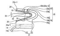
- the wire harness clip of this embodiment is shown, (A) is an exploded perspective view, and (B) is a cross-sectional view taken along line AA of the wire harness clip in which a C-type metal clip is attached to a C-type resin clip.
- It is a schematic perspective view which shows the state just before attaching the clip for wire harnesses attached to the wire harness to a bracket.
- It is a schematic side view which shows the state which pushed the bracket between the upper and lower pieces of the C-shaped metal clip, and was temporarily hold
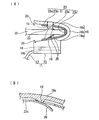
- the state which fixed the clip for wire harnesses to a bracket is shown, (A) is a schematic side view, (B) is a schematic sectional drawing which shows the pressing piece cut and raised by the protrusion for a press.
- It is a schematic perspective view which shows another example of the clip for wire harnesses of this invention. It is drawing which shows a prior art example.
- the wire harness clip 10 of the present embodiment includes a band-type wire harness mounting portion 11 that is wound around and fixed to the outer periphery of the wire harness W / H, and a flat plate shape made of metal or resin on the vehicle body side.
- the clip portion 15 is attached to the bracket 30.
- the band-type wire harness mounting portion 11 includes a band 12 that is wound around the outer periphery of the wire harness W / H, and a band fastening portion 13 that fastens and fixes the band 12.
- the band 12 is formed on one side surface of the band fastening portion 13.
- the band fastening portion 13 is provided with a band locking hole 14 for passing the band 12 wound around the wire harness W / H from the other side surface of the band fastening portion 13 to the one side surface and locking it.
- the wire claw 14a provided on the inner surface of the wire 12 is locked to the sawtooth-shaped locked groove 12a on the surface of the band 12, whereby the wire harness W / H is fastened and fixed by the band 12.
- the clip portion 15 includes a C-type resin clip 16 and a C-type metal clip 23 (made of iron-based metal) having a shorter length than the C-type resin clip 16.
- the C-type resin clip 16 includes a lower piece 16a protruding from the upper surface of the band fastening portion 13 and an upper piece 16c continuous through a bent portion 16b formed at one end of the lower piece 16a.
- the resin clip 16 and the band-type wire harness mounting portion 11 are integrally formed of resin.
- the C-type metal clip 23 also includes a lower piece 23a, a bent portion 23b, and an upper piece 23c. The C-type metal clip 23 is retracted toward the opening 18 side of the hollow portion sandwiched between the upper and lower pieces 16c and 16a of the C-type resin clip 16. Wear freely.
- the C-type resin clip 16 and the C-type metal clip 23 gradually reduce the distance between the upper and lower pieces facing from the openings 18 and 24 toward the bent portions 16b and 23b.
- the C-type metal clip 23 is a C-type resin. In a state of being arranged on the opening 18 side of the clip 16, there is an interval enough to temporarily hold the bracket 30 pushed between the upper and lower pieces 23 c and 23 a.
- a pressing piece 26 surrounded by a U-shaped slit 25 is provided at a position opposite to the upper and lower pieces 23c and 23a of the C-shaped metal clip 23.
- the U-shaped slit 25 has a U-shaped bent portion 25b disposed on the bent portion 23b side of the C-shaped metal clip 23 and a pair of U-shaped end portions 25a disposed on the opening 24 side of the C-shaped metal clip 23.
- the pressing piece 26 is cut and raised in the backward direction of the metal clip 23.
- pressing protrusions 19 for raising the pressing piece 26 toward the hollow portion when the C-type metal clip 23 is retracted.
- the pressing protrusion 19 is provided at a position where the pressing piece 26 can be pressed when the C-shaped metal clip 23 is retracted, and the pressing protrusion 19 increases in height toward the bent portion 16b side of the C-shaped resin clip 16. The half cone shape is gradually increased.
- a locking projection 20 is projected in the opposite direction at the opening side end of the upper and lower pieces 16c, 16a of the C-shaped resin clip 16, and before the bracket 30 is pushed in, the upper and lower pieces 23c, 23a of the C-shaped metal clip 23 are projected.
- the tips 23c-1 and 23a-1 are abutted against the locking projections 20 to prevent the C-shaped metal clip 23 from falling off in the opening direction.
- the upper and lower pieces 16c, 16a of the C-type resin clip 16 are provided with fitting grooves 21 on one side edge, and the upper and lower pieces 23c of the C-type metal clip 23 inserted into the hollow part of the C-type resin clip 16 from the other side edge side. , 23a are inserted and fitted into the fitting groove 21.
- a stopper piece 22 is provided on the other side edge of the upper piece 16c of the C-type resin clip 16, and after the C-type metal clip 23 is mounted, it is brought into contact with the other side edge 23c-3 of the upper piece 23c of the C-type metal clip 23. ing. With this configuration, the C-shaped metal clip 23 is prevented from falling off in the lateral direction.
- the attachment method to the bracket 30 of the clip 10 for wire harnesses of this embodiment is demonstrated.
- the band 12 of the wire harness clip 10 is wound around and fixed to the outer periphery of the wire harness W / H.
- the C-type metal clip 23 mounted on the opening side of the C-type resin clip 16 is not retracted as described above, and the upper and lower pieces 23c, 23a of the C-type metal clip 23 are not retracted.
- the bracket 30 is pushed in from the opening 24 (18) side and temporarily held (FIG. 3).
- the pressing piece 26 of the C-shaped metal clip 23 has not reached the pressing protrusion 19 of the C-type resin clip 16, the pressing piece 26 is not cut and raised.
- the wire harness clip 10 is moved laterally with respect to the bracket 30 to finally adjust the mounting position.
- the C-type resin clip 16 is advanced to the bracket 30 side so that the C-type metal clip 23 is retracted.
- the pressing piece 26 of the C-shaped metal clip 23 and the pressing protrusion 19 of the C-shaped resin clip 16 come into contact with each other, and the pressing piece 26 cut and raised to the hollow side by the pressing protrusion 19 as shown in FIG.
- the upper and lower surfaces of the bracket 30 are clamped [FIG. 4 (A)].
- the wire harness clip 10 can be securely fixed to the proper attachment position of the finally adjusted bracket 30 by a single attachment operation.
- the clip for wire harnesses of the present invention is limited to the wire harness clip 10 provided with the band-type wire harness mounting portion 11 for winding and fixing the band 12 around the wire harness W / H as in the present embodiment.
- a wire harness clip having a substrate-type wire harness mounting portion 110 that is wound around the wire harness W / H with an adhesive tape T, and a C-type resin clip 160 protruding from the surface of the intermediate portion. 100 may be sufficient.
Landscapes
- Engineering & Computer Science (AREA)
- General Engineering & Computer Science (AREA)
- Mechanical Engineering (AREA)
- Architecture (AREA)
- Civil Engineering (AREA)
- Structural Engineering (AREA)
- Installation Of Indoor Wiring (AREA)
- Clamps And Clips (AREA)
- Connection Of Plates (AREA)
Abstract
Description
前記バンド型ワイヤハーネス取付部のバンド締結部の外面または前記基板型ワイヤハーネス取付部の基板の中間部の表面に突設した下片と、該下片の一端に形成した屈曲部を介して連続する上片とからなるC型樹脂クリップと、
前記C型樹脂クリップより長さが短いC型金属クリップを備え、
前記C型樹脂クリップの上下片で挟まれた中空部の開口側に、前記C型金属クリップを後退自在に装着し、かつ、
前記C型樹脂クリップの上下片の対向する各内面に押圧用突起を設けると共に、前記C型金属クリップの上下片にU字状スリットで囲まれた押下片を設けており、
平板状のブラケットを前記C型金属クリップの上下片間に押し込んで該C型金属クリップを後退させると、前記押圧用突起で前記押下片を切り起こして前記ブラケットの上下両面を挟持する構成としているワイヤハーネス用クリップを提供している。
よって、ワイヤハーネス用クリップを車体側の金属製または樹脂製のブラケットに取り付ける際に、まず、C型金属クリップをC型樹脂クリップ内で後退させずにブラケットをC型金属クリップの上下片間に押し込むことにより、ワイヤハーネス用クリップをブラケットに対して横移動可能な状態で仮保持することができる。よって、この段階で取付位置の最終調整を行うことができる。また、取付位置の最終調整後にC型金属クリップを後退させるだけで、押圧用突起によって切り起こされた押下片でブラケットの上下両面を挟持することができる。よって、前記最終調整したブラケットの適正取付位置に、ワイヤハーネス用クリップを一度の取付作業で確実に固定することができる。
また、前記押下片はC型金属クリップの後退方向に向けて切り起こされることが好ましい。よって、前記押下片を囲むU字状スリットは、U字の屈曲部をC型金属クリップの屈曲部側(奥側)に配置し、U字の一対の端部をC型金属クリップの開口側(手前側)に配置することが好ましい。
さらに、前記C型樹脂クリップの押圧用突起は、C型金属クリップを後退させたときに押下片を押圧できる位置に設けておき、前記押圧用突起はC型樹脂クリップの屈曲部側(奥側)に向けて高さを漸増させた半円錐形状としていることが好ましい。
前記ストッパー片はC型樹脂クリップの上片でなく下片の他側縁に設けてもよいし、C型樹脂クリップの上下片両方の他側縁に設けてもよいが、ストッパー片の形成のし易さやC型樹脂クリップへのC型金属クリップの装着のし易さ等からC型樹脂クリップ上片の他側縁に設けることが好ましい。
また、前記C型樹脂クリップと、前記バンド型または基板型ワイヤハーネス取付部とは樹脂で一体成形されていることが好ましい。
該仮保持状態で前記クリップを前記ブラケットに対して横移動させて取付位置の最終調整を行い、
最終取付位置で、前記ブラケットが前記C型金属クリップをC型樹脂クリップ内で後退させるように、C型樹脂クリップをブラケット側に前進させて本固定するワイヤハーネス用クリップの車体取付方法を提供している。
よって、ワイヤハーネス用クリップにワイヤハーネスを取り付け、該ワイヤハーネスを車両に配索する際に、C型金属クリップをC型樹脂クリップ内で後退させることなくブラケットをC型金属クリップの上下片間に押し込むことにより、ワイヤハーネス用クリップをブラケットに対して横移動可能な状態で仮保持することができる。したがって、前記仮保持状態でワイヤハーネス用クリップをブラケットに対して横方向に移動させて取付位置の最終調整を行うことができる。また、前記取付位置の最終調整後に、C型金属クリップを後退させるようにC型樹脂クリップをブラケット側に前進させることで、押圧用突起によって切り起こされた押下片でブラケットの上下両面を挟持することができる。よって、前記最終調整したブラケットの適正取付位置に、ワイヤハーネス用クリップを一度の取付作業で確実に本固定することができる。
図1乃至図4は本実施形態を示している。本実施形態のワイヤハーネス用クリップ10は、図2に示すように、ワイヤハーネスW/Hの外周に巻き付けて固定するバンド型ワイヤハーネス取付部11と、車体側の金属製または樹脂製の平板状のブラケット30に取り付けるクリップ部15とから構成している。
前記バンド型ワイヤハーネス取付部11は、ワイヤハーネスW/Hの外周に巻き付けるバンド12と、該バンド12を締結固定するバンド締結部13とから構成し、バンド12をバンド締結部13の一側面の下辺近傍位置から突設している。バンド締結部13には、ワイヤハーネスW/Hに巻き付けたバンド12をバンド締結部13の他側面から一側面へと貫通させて係止するバンド係止穴14を設け、該バンド係止穴14の内面に設けた係止爪14aをバンド12表面の鋸歯状の被係止溝12aに係止させることにより、バンド12でワイヤハーネスW/Hを締め付け固定する構成としている。
さらに、C型樹脂クリップ16の上下片16c、16aの一側縁に嵌合溝部21を夫々設け、他側縁側からC型樹脂クリップ16の中空部に挿入したC型金属クリップ23の上下片23c、23aの一側縁23c-2、23a-2を嵌合溝部21に挿入して装着している。また、C型樹脂クリップ16の上片16cの他側縁にストッパー片22を設け、C型金属クリップ23の装着後にC型金属クリップ23の上片23cの他側縁23c-3に当接させている。前記構成とすることで、C型金属クリップ23の横方向への脱落を防止している。
まず、ワイヤハーネスW/Hの外周にワイヤハーネス用クリップ10のバンド12を巻き付けて固定する。ワイヤハーネスW/Hの車両配索時には、前記のようにC型樹脂クリップ16の開口側に装着したC型金属クリップ23を後退させることなく、C型金属クリップ23の上下片23c、23aの間にブラケット30を開口24(18)側より押し込んで仮保持する(図3)。この段階ではC型金属クリップ23の押下片26がC型樹脂クリップ16の押圧用突起19に到達していないため、押下片26は切り起こされていない。この仮保持状態でワイヤハーネス用クリップ10をブラケット30に対して横移動させて取付位置の最終調整を行う。
11 バンド型ワイヤハーネス取付部
12 バンド
13 バンド締結部
16 C型樹脂クリップ
16a 下片
16b 屈曲部
16c 上片
18 開口
19 押圧用突起
20 係止突起
21 嵌合溝部
22 ストッパー片
23 C型金属クリップ
23a 下片
23b 屈曲部
23c 上片
24 開口
25 U字状スリット
26 押下片
30 ブラケット
110 基板型ワイヤハーネス取付部
Claims (4)
- バンドをワイヤハーネスに巻き付けて固定するバンド型ワイヤハーネス取付部またはワイヤハーネスに粘着テープで巻き付ける基板型ワイヤハーネス取付部と、
前記バンド型ワイヤハーネス取付部のバンド締結部の外面または前記基板型ワイヤハーネス取付部の基板の中間部の表面に突設した下片と、該下片の一端に形成した屈曲部を介して連続する上片とからなるC型樹脂クリップと、
前記C型樹脂クリップより長さが短いC型金属クリップを備え、
前記C型樹脂クリップの上下片で挟まれた中空部の開口側に、前記C型金属クリップを後退自在に装着し、かつ、
前記C型樹脂クリップの上下片の対向する各内面に押圧用突起を設けると共に、前記C型金属クリップの上下片にU字状スリットで囲まれた押下片を設けており、
平板状のブラケットを前記C型金属クリップの上下片間に押し込んで該C型金属クリップを後退させると、前記押圧用突起で前記押下片を切り起こして前記ブラケットの上下両面を挟持する構成としているワイヤハーネス用クリップ。 - 前記C型樹脂クリップの上下片の開口側先端に対向方向に突出する係止突起を設け、前記ブラケットの押し込み前には、前記C型金属クリップの上下片の先端を前記係止突起に突き当てている請求項1に記載のワイヤハーネス用クリップ。
- 前記C型樹脂クリップの上下片の一側縁の内面に沿って嵌合溝部を設け、前記C型金属クリップの一側縁を前記嵌合溝部に挿入して装着する一方、該装着後にC型金属クリップの上片の他側縁に当接させるストッパー片を前記C型樹脂クリップの上片の他側縁に設けている請求項1または請求項2に記載のワイヤハーネス用クリップ。
- 請求項1乃至請求項3のいずれか1項に記載のワイヤハーネス用クリップをワイヤハーネスに取り付け、該ワイヤーネスの車両配索時に、前記ブラケットを前記C型金属クリップの上下片の間に押し込んで仮保持し、
該仮保持状態で前記クリップを前記ブラケットに対して横移動させて取付位置の最終調整を行い、
最終取付位置で、前記ブラケットが前記C型金属クリップをC型樹脂クリップ内で後退させるように、C型樹脂クリップをブラケット側に前進させて本固定するワイヤハーネス用クリップの車体取付方法。
Priority Applications (3)
| Application Number | Priority Date | Filing Date | Title |
|---|---|---|---|
| US13/704,112 US8757562B2 (en) | 2010-08-05 | 2011-03-28 | Wire harness clip and method of mounting wire harness clip onto vehicle |
| GB1223028.0A GB2495432B (en) | 2010-08-05 | 2011-03-28 | Wire harness clip and method of mounting wire harness clip onto vehicle |
| CN2011800385973A CN103069678A (zh) | 2010-08-05 | 2011-03-28 | 线束夹和将线束夹安装在车辆上的方法 |
Applications Claiming Priority (2)
| Application Number | Priority Date | Filing Date | Title |
|---|---|---|---|
| JP2010-176787 | 2010-08-05 | ||
| JP2010176787A JP5408068B2 (ja) | 2010-08-05 | 2010-08-05 | ワイヤハーネス用クリップおよびワイヤハーネス用クリップの車体取付方法 |
Publications (1)
| Publication Number | Publication Date |
|---|---|
| WO2012017706A1 true WO2012017706A1 (ja) | 2012-02-09 |
Family
ID=45559221
Family Applications (1)
| Application Number | Title | Priority Date | Filing Date |
|---|---|---|---|
| PCT/JP2011/057595 Ceased WO2012017706A1 (ja) | 2010-08-05 | 2011-03-28 | ワイヤハーネス用クリップおよびワイヤハーネス用クリップの車体取付方法 |
Country Status (5)
| Country | Link |
|---|---|
| US (1) | US8757562B2 (ja) |
| JP (1) | JP5408068B2 (ja) |
| CN (1) | CN103069678A (ja) |
| GB (1) | GB2495432B (ja) |
| WO (1) | WO2012017706A1 (ja) |
Cited By (4)
| Publication number | Priority date | Publication date | Assignee | Title |
|---|---|---|---|---|
| US10851820B2 (en) | 2018-12-28 | 2020-12-01 | A. Raymond Et Cie | Self-locking edge clip assembly |
| USD944632S1 (en) | 2019-10-17 | 2022-03-01 | A. Raymond Et Cie | Edge clip |
| US11420571B1 (en) | 2021-02-25 | 2022-08-23 | A. Raymond Et Cie | Serviceable edge clip assembly |
| US11603873B2 (en) | 2020-09-30 | 2023-03-14 | A. Raymond Et Cie | Heavy duty fastening assembly with installation verification |
Families Citing this family (28)
| Publication number | Priority date | Publication date | Assignee | Title |
|---|---|---|---|---|
| CN102472415B (zh) * | 2009-07-07 | 2017-07-07 | 伊利诺斯工具制品有限公司 | 自定心的电缆扎带 |
| US8955902B2 (en) * | 2011-05-11 | 2015-02-17 | Caterpillar Inc. | Universal fastening device |
| JP5957781B2 (ja) * | 2012-02-17 | 2016-07-27 | 矢崎総業株式会社 | 摺動式クランプ及びクランプ対象部材取り付け構造 |
| CN107264440B (zh) * | 2012-10-29 | 2019-11-15 | 古河电气工业株式会社 | 布线线束 |
| WO2014143288A1 (en) * | 2013-03-15 | 2014-09-18 | United Technologies Corporation | Modular mount assembly |
| JP6048305B2 (ja) * | 2013-05-10 | 2016-12-21 | 住友電装株式会社 | バンドクリップ、バンドクリップ付きワイヤーハーネス及び組み立て品 |
| FR3014531B1 (fr) * | 2013-12-09 | 2016-05-06 | Trw Automotive Elect & Components Gmbh | Dispositif de fixation pour cable |
| GB2521184A (en) * | 2013-12-12 | 2015-06-17 | Oxti Corp | Cable Organising Apparatus |
| FI126934B (fi) * | 2014-05-14 | 2017-08-15 | Suomen Visor Oy | Aurinkosuojan kiinnike |
| CN106463936A (zh) * | 2014-06-06 | 2017-02-22 | 矢崎总业株式会社 | 线束布设结构 |
| SE538496C2 (en) * | 2014-07-11 | 2016-08-09 | Resorbable Devices Ab | Cable tie based medical device |
| US9908021B2 (en) * | 2015-01-02 | 2018-03-06 | Fab Six Products Llc | Turf repair apparatus |
| DE102015102825B3 (de) * | 2015-02-27 | 2016-04-28 | Lisa Dräxlmaier GmbH | Klemme |
| US20170063064A1 (en) | 2015-08-24 | 2017-03-02 | William Gary Gintz | Releasable holder for cables and conduit |
| US20190267785A1 (en) | 2015-08-24 | 2019-08-29 | Sticnstac, LLC | Releasable holder for cables and conduit |
| JP6551216B2 (ja) * | 2015-12-18 | 2019-07-31 | 住友電装株式会社 | クリップ装置 |
| WO2017199842A1 (ja) * | 2016-05-18 | 2017-11-23 | 株式会社パイオラックス | クリップ |
| JP6842638B2 (ja) * | 2017-05-24 | 2021-03-17 | 住友電装株式会社 | 配線ユニット |
| JP6819523B2 (ja) * | 2017-06-14 | 2021-01-27 | 株式会社オートネットワーク技術研究所 | 支持部材付ワイヤーハーネスおよびワイヤーハーネスの支持構造 |
| DE102017118047B4 (de) * | 2017-08-08 | 2025-03-27 | Norma Germany Gmbh | Schelle zum Befestigen eines rohr- oder schlauchförmigen Gegenstands |
| US11116192B2 (en) * | 2017-10-04 | 2021-09-14 | Gye S. Nitta | Live bait zip tie |
| US10777334B2 (en) * | 2017-12-05 | 2020-09-15 | Aptiv Technologies Limited | Wiring harness assembly having multiple separated conductors embedded within a substrate |
| US11242945B2 (en) * | 2019-09-24 | 2022-02-08 | Autronic Plastics, Inc. | Hanger for messenger wire |
| US11608122B2 (en) | 2020-06-04 | 2023-03-21 | Honda Motor Co., Ltd. | Dual orthogonal mounting system |
| DE202021105021U1 (de) * | 2021-09-17 | 2022-12-22 | Hellermanntyton Gmbh | Modularer Kantenclip |
| JP7822226B2 (ja) * | 2022-03-30 | 2026-03-02 | 古河電気工業株式会社 | 仮保持部材及び仮保持具付ワイヤーハーネス |
| US12571414B2 (en) | 2023-02-17 | 2026-03-10 | Ford Motor Company | Retainer for securing component to structure |
| CN118205499B (zh) * | 2024-05-22 | 2024-07-12 | 四川灵筠新能源汽车科技有限公司 | 一种碳纤维复合材料的汽车线路安装结构 |
Citations (4)
| Publication number | Priority date | Publication date | Assignee | Title |
|---|---|---|---|---|
| JPH10331814A (ja) * | 1997-05-28 | 1998-12-15 | Togo Seisakusho Corp | 線状材用のクランプ |
| JP2000152467A (ja) * | 1998-11-05 | 2000-05-30 | Sumitomo Wiring Syst Ltd | ボルト止めクリップ |
| JP2008259363A (ja) * | 2007-04-06 | 2008-10-23 | Daiwa Kasei Ind Co Ltd | クリップ |
| JP2009225616A (ja) * | 2008-03-18 | 2009-10-01 | Nippon Pop Rivets & Fasteners Ltd | 複数本のワイヤハーネスのクランプ |
Family Cites Families (9)
| Publication number | Priority date | Publication date | Assignee | Title |
|---|---|---|---|---|
| JP3127215B2 (ja) | 1993-09-27 | 2001-01-22 | 株式会社東郷製作所 | ワイヤハーネス用クランプ |
| JPH1113941A (ja) * | 1997-06-19 | 1999-01-22 | Sumitomo Wiring Syst Ltd | ブラケット係止用のクランプ |
| JP3410664B2 (ja) | 1998-07-14 | 2003-05-26 | シャープ株式会社 | 液晶表示装置 |
| KR20030062759A (ko) * | 2002-01-18 | 2003-07-28 | 경신공업 주식회사 | 와이어 하네스 고정용 클립 |
| DE102005045840B4 (de) * | 2005-09-24 | 2008-10-23 | A. Raymond Et Cie | Vorrichtung zum Halten einer länglichen Gegenstandsanordnung |
| DE202007000938U1 (de) * | 2007-01-22 | 2007-04-19 | Trw Automotive Electronics & Components Gmbh & Co. Kg | Befestigungsvorrichtung für Kabel |
| US8726468B2 (en) * | 2009-03-18 | 2014-05-20 | Hellermanntyton Corporation | Bundle tie with head dampener |
| CN201430383Y (zh) * | 2009-06-18 | 2010-03-24 | 河南天海电器有限公司 | 一种带弹簧卡结构的汽车电线束固定夹 |
| US20130067695A1 (en) * | 2011-09-16 | 2013-03-21 | Fiber Instrument Sales, Inc. | Wide Cushioned Cable Tie for Optical Fiber Bundle |
-
2010
- 2010-08-05 JP JP2010176787A patent/JP5408068B2/ja not_active Expired - Fee Related
-
2011
- 2011-03-28 US US13/704,112 patent/US8757562B2/en not_active Expired - Fee Related
- 2011-03-28 CN CN2011800385973A patent/CN103069678A/zh active Pending
- 2011-03-28 WO PCT/JP2011/057595 patent/WO2012017706A1/ja not_active Ceased
- 2011-03-28 GB GB1223028.0A patent/GB2495432B/en not_active Expired - Fee Related
Patent Citations (4)
| Publication number | Priority date | Publication date | Assignee | Title |
|---|---|---|---|---|
| JPH10331814A (ja) * | 1997-05-28 | 1998-12-15 | Togo Seisakusho Corp | 線状材用のクランプ |
| JP2000152467A (ja) * | 1998-11-05 | 2000-05-30 | Sumitomo Wiring Syst Ltd | ボルト止めクリップ |
| JP2008259363A (ja) * | 2007-04-06 | 2008-10-23 | Daiwa Kasei Ind Co Ltd | クリップ |
| JP2009225616A (ja) * | 2008-03-18 | 2009-10-01 | Nippon Pop Rivets & Fasteners Ltd | 複数本のワイヤハーネスのクランプ |
Cited By (4)
| Publication number | Priority date | Publication date | Assignee | Title |
|---|---|---|---|---|
| US10851820B2 (en) | 2018-12-28 | 2020-12-01 | A. Raymond Et Cie | Self-locking edge clip assembly |
| USD944632S1 (en) | 2019-10-17 | 2022-03-01 | A. Raymond Et Cie | Edge clip |
| US11603873B2 (en) | 2020-09-30 | 2023-03-14 | A. Raymond Et Cie | Heavy duty fastening assembly with installation verification |
| US11420571B1 (en) | 2021-02-25 | 2022-08-23 | A. Raymond Et Cie | Serviceable edge clip assembly |
Also Published As
| Publication number | Publication date |
|---|---|
| JP2012039729A (ja) | 2012-02-23 |
| CN103069678A (zh) | 2013-04-24 |
| US8757562B2 (en) | 2014-06-24 |
| GB2495432A (en) | 2013-04-10 |
| GB2495432B (en) | 2015-04-15 |
| US20130092803A1 (en) | 2013-04-18 |
| JP5408068B2 (ja) | 2014-02-05 |
| GB201223028D0 (en) | 2013-02-06 |
Similar Documents
| Publication | Publication Date | Title |
|---|---|---|
| JP5408068B2 (ja) | ワイヤハーネス用クリップおよびワイヤハーネス用クリップの車体取付方法 | |
| US8726473B2 (en) | Clipping fixation device allowing an adjustment in two directions | |
| US7819365B2 (en) | Fastening device for cables | |
| US8572805B2 (en) | Grommet | |
| US20140326836A1 (en) | Cable fixing clip for preventing reverse-assembly | |
| KR20080045692A (ko) | 호스 클램프 | |
| US20140196259A1 (en) | Fastening clip | |
| AU2014268101A1 (en) | Attachment element | |
| JP7235570B2 (ja) | クランプ | |
| JP2011094645A (ja) | ワイヤーハーネス保持用クリップ | |
| WO2013132710A1 (ja) | スリット装着部材装着治具、ワイヤーハーネスの製造方法及びスリット装着部材 | |
| US9638225B2 (en) | Closure element for a fire-protection sleeve | |
| JP2018070192A (ja) | 結束バンド及び外装部材付ワイヤーハーネス | |
| JP2016195479A (ja) | ワイヤハーネスの固定構造 | |
| KR101869859B1 (ko) | 복층 유리 내부에 디스플레이장치를 설치하기 위한 와이어홀딩장치 | |
| US20150353147A1 (en) | Assembly for tensioning a cable and method of using the same | |
| JP5053018B2 (ja) | ワイヤーハーネス用クリップ | |
| JP2016023705A (ja) | ハーネス用固定具 | |
| JP6027526B2 (ja) | 車両用バイザ | |
| JPH04310423A (ja) | トリムパネルを支持パネルに取り付ける固定装置 | |
| JP2013143849A (ja) | ハーネスクランプ | |
| WO2017126460A1 (ja) | 車載電線用の結束具およびワイヤハーネス | |
| JP2007267460A (ja) | ワイヤハーネス係止体 | |
| JP2014150609A (ja) | ベルトクランプ及びワイヤーハーネス | |
| JP2014155293A (ja) | バンドクランプ |
Legal Events
| Date | Code | Title | Description |
|---|---|---|---|
| WWE | Wipo information: entry into national phase |
Ref document number: 201180038597.3 Country of ref document: CN |
|
| 121 | Ep: the epo has been informed by wipo that ep was designated in this application |
Ref document number: 11814337 Country of ref document: EP Kind code of ref document: A1 |
|
| WWE | Wipo information: entry into national phase |
Ref document number: 13704112 Country of ref document: US |
|
| ENP | Entry into the national phase |
Ref document number: 1223028 Country of ref document: GB Kind code of ref document: A Free format text: PCT FILING DATE = 20110328 |
|
| WWE | Wipo information: entry into national phase |
Ref document number: 1223028.0 Country of ref document: GB |
|
| NENP | Non-entry into the national phase |
Ref country code: DE |
|
| 122 | Ep: pct application non-entry in european phase |
Ref document number: 11814337 Country of ref document: EP Kind code of ref document: A1 |