WO2012017662A1 - 画像復元装置および画像復元方法 - Google Patents
画像復元装置および画像復元方法 Download PDFInfo
- Publication number
- WO2012017662A1 WO2012017662A1 PCT/JP2011/004426 JP2011004426W WO2012017662A1 WO 2012017662 A1 WO2012017662 A1 WO 2012017662A1 JP 2011004426 W JP2011004426 W JP 2011004426W WO 2012017662 A1 WO2012017662 A1 WO 2012017662A1
- Authority
- WO
- WIPO (PCT)
- Prior art keywords
- psf
- image
- frequency
- images
- input
- Prior art date
- Legal status (The legal status is an assumption and is not a legal conclusion. Google has not performed a legal analysis and makes no representation as to the accuracy of the status listed.)
- Ceased
Links
Images










Classifications
-
- H—ELECTRICITY
- H04—ELECTRIC COMMUNICATION TECHNIQUE
- H04N—PICTORIAL COMMUNICATION, e.g. TELEVISION
- H04N1/00—Scanning, transmission or reproduction of documents or the like, e.g. facsimile transmission; Details thereof
- H04N1/40—Picture signal circuits
- H04N1/409—Edge or detail enhancement; Noise or error suppression
- H04N1/4092—Edge or detail enhancement
-
- G—PHYSICS
- G06—COMPUTING OR CALCULATING; COUNTING
- G06T—IMAGE DATA PROCESSING OR GENERATION, IN GENERAL
- G06T5/00—Image enhancement or restoration
- G06T5/73—Deblurring; Sharpening
-
- H—ELECTRICITY
- H04—ELECTRIC COMMUNICATION TECHNIQUE
- H04N—PICTORIAL COMMUNICATION, e.g. TELEVISION
- H04N23/00—Cameras or camera modules comprising electronic image sensors; Control thereof
- H04N23/60—Control of cameras or camera modules
- H04N23/68—Control of cameras or camera modules for stable pick-up of the scene, e.g. compensating for camera body vibrations
- H04N23/681—Motion detection
- H04N23/6811—Motion detection based on the image signal
-
- H—ELECTRICITY
- H04—ELECTRIC COMMUNICATION TECHNIQUE
- H04N—PICTORIAL COMMUNICATION, e.g. TELEVISION
- H04N23/00—Cameras or camera modules comprising electronic image sensors; Control thereof
- H04N23/60—Control of cameras or camera modules
- H04N23/68—Control of cameras or camera modules for stable pick-up of the scene, e.g. compensating for camera body vibrations
- H04N23/682—Vibration or motion blur correction
- H04N23/684—Vibration or motion blur correction performed by controlling the image sensor readout, e.g. by controlling the integration time
- H04N23/6845—Vibration or motion blur correction performed by controlling the image sensor readout, e.g. by controlling the integration time by combination of a plurality of images sequentially taken
-
- G—PHYSICS
- G06—COMPUTING OR CALCULATING; COUNTING
- G06T—IMAGE DATA PROCESSING OR GENERATION, IN GENERAL
- G06T2207/00—Indexing scheme for image analysis or image enhancement
- G06T2207/20—Special algorithmic details
- G06T2207/20048—Transform domain processing
- G06T2207/20056—Discrete and fast Fourier transform, [DFT, FFT]
-
- G—PHYSICS
- G06—COMPUTING OR CALCULATING; COUNTING
- G06T—IMAGE DATA PROCESSING OR GENERATION, IN GENERAL
- G06T2207/00—Indexing scheme for image analysis or image enhancement
- G06T2207/20—Special algorithmic details
- G06T2207/20212—Image combination
- G06T2207/20221—Image fusion; Image merging
Definitions
- the present invention relates to an image restoration apparatus and an image restoration method that reduce blurring that occurs in an image obtained by combining a plurality of input images that are continuously shot.
- noise may be added to the image depending on the characteristics of the readout circuit of the CCD (Charge-Coupled Device) sensor or CMOS (Complementary Metal Oxide Semiconductor) sensor and the characteristics of the transmission path.
- CCD Charge-Coupled Device
- CMOS Complementary Metal Oxide Semiconductor
- image blur due to out of focus (out-of-focus) at the time of shooting or blur due to hand shake (camera shake) may occur.
- an image photographed with a digital camera is deteriorated by adding blur caused by an artificial operation at the time of photographing to noise caused by characteristics unique to the imaging apparatus.
- blurring due to camera movement during shooting (exposure) is referred to as “motion blur”, and blur due to out-of-focus (out-of-focus). Blur).
- the exposure time is lengthened, a lot of light incident from the subject is accumulated and an image with less noise can be obtained. Therefore, the signal is not buried with noise.
- the method of extending the exposure time has a problem that the image is blurred due to camera shake during the exposure time.
- optical camera shake correction which is a method of shifting the lens
- Another method is to obtain the direction and size of blur from the obtained image, and to restore the image by signal processing based on the obtained direction and size of blur (restoration method by signal processing).
- Patent Documents 2 to 4 and Non-Patent Documents 1 to 7 For example, see Patent Documents 2 to 4 and Non-Patent Documents 1 to 7).
- a function that represents the luminance of each pixel in the degraded image is obtained by convolution of a function that represents the luminance of each pixel in the ideal image and a point spread function (PSF) that represents image blurring.
- PSF point spread function
- deconvolution of the degraded image and the PSF may be performed.
- the convolution operation corresponds to multiplication in the frequency domain. Therefore, a restored image can be obtained by dividing the degraded image by the PSF in the frequency domain.
- Non-Patent Document 1 For PSF estimation, for example, a sparse coding method disclosed in Non-Patent Document 1 is known. In this method, a first restoration result is first obtained from an initial PSF and a deteriorated image given manually. Subsequently, a PSF that is considered to be closer to the true PSF is estimated using the first restoration result and the deteriorated image, and the initial PSF is corrected with the estimated PSF. A second restoration result is obtained from the degraded image using the corrected PSF. Thereafter, by repeating the operation of obtaining the Nth restored image from the (N ⁇ 1) th PSF and the degraded image and estimating the Nth PSF from the Nth restored image and the degraded image, the PSF is repeated. Estimation and degraded image restoration at the same time.
- FIG. 1A is a diagram showing an image (ideal image in the vicinity of an edge) in which the luminance changes stepwise.
- FIG. 1B is a graph schematically showing the luminance distribution of the ideal image.
- FIG. 2A is a diagram illustrating a deteriorated image (blurred image) in the vicinity of an edge obtained by photographing the image of FIG. 1A with a camera.
- FIG. 2B is a graph schematically showing the luminance distribution of the deteriorated image.
- FIG. 3A is a diagram showing a restored image obtained by restoring the deteriorated image of FIG. 2A by signal processing.
- FIG. 3B is a graph schematically showing the luminance distribution of the restored image.
- the restored image of FIG. 3A there is a portion where the luminance changes periodically.
- Such a luminance change is noise called “ringing”. Ringing occurs due to the presence of a frequency (hereinafter referred to as “zero point”) in which the amplitude value of the PSF is 0 or close to 0 in the frequency domain.
- Patent Documents 3 and 4 and Non-Patent Documents 6 and 7. According to these techniques, the amplitude value of the PSF is 0 in the frequency domain by blocking light according to a predetermined time pattern (encoding pattern) instead of keeping the shutter open during the exposure state. Frequency can be reduced. Therefore, ringing noise can be prevented from occurring.
- the methods disclosed in Patent Documents 3 and 4 and Non-Patent Documents 6 and 7 are called “Coded Exposure Photography”.
- Non-Patent Document 6 the occurrence of ringing in the restored image can be suppressed by performing exposure encoding.
- the encoding pattern is expressed as a binary binary pattern, and a binary pattern optimum for image restoration is searched from among a plurality of binary patterns.
- a binary pattern optimum for image restoration is searched from among a plurality of binary patterns.
- Non-Patent Document 7 in order to determine an optimal coding pattern for image restoration, restoration is performed while changing the coding pattern, the noise amount of the restored image is measured, and the optimum pattern is restored. It is determined whether or not restoration is possible.
- Non-Patent Document 7 searches for an optimum pattern within a range of some patterns instead of all patterns. Therefore, there is a problem that it is not always possible to search for an optimum one in terms of performance.
- the present invention solves the above-described conventional problems, and provides an image restoration apparatus and an image restoration method capable of stably suppressing the occurrence of ringing while suppressing an increase in processing load. With the goal.
- an image restoration apparatus is an image restoration apparatus that reduces blurring that occurs in an image obtained by combining a plurality of continuously captured input images.
- a PSF acquisition unit that acquires a first PSF (Point Spread Function) indicating a blur occurring over a plurality of input images
- a PSF conversion unit that generates a second PSF
- an image conversion unit that generates a plurality of converted images by converting each of the plurality of input images using a portion corresponding to each input image of the second PSF
- By performing a restoration process using the second PSF on the degraded image obtained by combining the plurality of converted images a restored image is obtained.
- an image restoring unit which generates.
- a second PSF having an amplitude value of each frequency equal to or greater than a threshold value in the frequency domain is generated.
- each input image is converted using each part of the second PSF.
- An image obtained by synthesizing a plurality of input images converted in this way is a degraded image (hereinafter referred to as “encoded degraded image”) obtained when the PSF is encoded so that no zero point is generated. Equivalent to. That is, according to this configuration, it is possible to generate a deteriorated image that is encoded so that no zero point is generated in the PSF, while adapting to blurring that occurs over a plurality of input images.
- the PSF conversion unit identifies a frequency in which an amplitude value of the first PSF is less than the threshold value in a frequency domain, and changes the amplitude value to a predetermined value equal to or greater than the threshold value in the identified frequency. It is preferable to process 1PSF.
- the second PSF is generated by changing the amplitude value at a frequency at which the amplitude value of the first PSF is less than the threshold value. Therefore, it is possible to generate an encoded deteriorated image adapted to blurring occurring over a plurality of input images. That is, a restored image with less blur can be generated.
- the predetermined value used when changing the amplitude value of the first frequency is larger than the predetermined value used when changing the amplitude value of the second frequency, which is a higher frequency than the first frequency. Is preferred.
- the amplitude value of the low frequency can be made larger than the amplitude value of the high frequency at the frequency where the amplitude value is changed, ringing noise that is noise generated in the low frequency region is efficiently reduced. It becomes possible to make it.
- the predetermined value is a value determined so as to decrease as the noise generated in the input image increases.
- the threshold value used when specifying the first frequency is larger than the threshold value used when specifying the second frequency that is higher than the first frequency.
- the threshold value is a value determined so as to decrease as the noise generated in the input image increases.
- the image conversion unit is a portion of the second PSF that corresponds to each input image in time based on the time when the blur indicated by the second PSF is detected and the time when each input image is captured. It is preferable that each of the plurality of input images is converted using the determined portion.
- This configuration makes it possible to more appropriately determine the portion of the second PSF corresponding to each input image.
- the PSF conversion unit identifies a frequency in which an amplitude value of the first PSF is less than the threshold in a frequency domain, generates an offset PSF in which the amplitude value of the identified frequency is equal to or greater than the threshold, and the offset PSF It is preferable that the second PSF is generated by adding the first PSF to the first PSF.
- the second PSF can be generated by adding the offset PSF.
- the present invention can be realized not only as an image restoration apparatus including such a characteristic processing unit, but also as an image restoration method using the characteristic processing unit included in the image restoration apparatus as a step. . It can also be realized as a computer program that causes a computer to execute the characteristic steps included in the image restoration method. Needless to say, such a computer program can be distributed via a computer-readable recording medium such as a CD-ROM (Compact Disc Only Memory) or a communication network such as the Internet.
- a computer-readable recording medium such as a CD-ROM (Compact Disc Only Memory) or a communication network such as the Internet.
- the present invention can also be realized as an integrated circuit having a characteristic processing unit included in the image restoration apparatus.
- a deteriorated image encoded so that a zero point does not occur in the PSF is applied to a blur generated over a plurality of input images by using a plurality of input images continuously captured. Can be generated. Therefore, it is possible to stably suppress the occurrence of ringing while suppressing an increase in processing load.
- FIG. 1A is a diagram illustrating an ideal image near an edge.
- FIG. 1B is a graph schematically showing the luminance distribution of the ideal image.
- FIG. 2A is a diagram showing a deteriorated image near the edge.
- FIG. 2B is a graph schematically showing the luminance distribution of the deteriorated image.
- FIG. 3A is a diagram illustrating a restored image obtained by restoring a deteriorated image by signal processing.
- FIG. 3B is a graph schematically showing the luminance distribution of the restored image.
- FIG. 4 is an explanatory diagram of exposure encoding.
- FIG. 5 is a schematic diagram of the PSF in the spatial domain.
- FIG. 6 is a schematic diagram of the PSF converted into the frequency domain.
- FIG. 5 is a schematic diagram of the PSF in the spatial domain.
- FIG. 7 is a block diagram illustrating a functional configuration of the imaging apparatus according to the embodiment of the present invention.
- FIG. 8 is a block diagram showing a functional configuration of the signal processing unit according to the embodiment of the present invention.
- FIG. 9 is a flowchart showing a flow of a degraded image restoration process in the signal processing unit according to the embodiment of the present invention.
- FIG. 10 is a flowchart showing a flow of PSF conversion processing in the PSF conversion unit according to the embodiment of the present invention.
- FIG. 11 is a flowchart showing a flow of image conversion processing in the image conversion unit according to the embodiment of the present invention.
- FIG. 12 is a diagram illustrating an example of an ideal image.
- FIG. 13 is a diagram illustrating an example of frequency characteristics of an ideal image.
- FIG. 14 is a diagram illustrating an example of the first PSF.
- FIG. 15 is a diagram illustrating an example of frequency characteristics of the first PSF.
- FIG. 16 is a diagram illustrating an example of a deteriorated image.
- FIG. 17 is a diagram illustrating an example of frequency characteristics of a deteriorated image.
- FIG. 18 is a diagram illustrating an example of a restored image obtained by a conventional image restoration method.
- FIG. 19 is a diagram illustrating an example of the second PSF.
- FIG. 20 is a diagram illustrating an example of frequency characteristics of the second PSF.
- FIG. 21 is a diagram showing an example of a restored image obtained by the image restoration method according to the embodiment of the present invention.
- FIG. 22 is a block diagram illustrating a functional configuration of the image restoration device according to one aspect of the present invention.
- the luminance distribution of an image formed on the imaging surface is represented by m (x, y).
- the coordinates (x, y) are two-dimensional coordinates indicating the position of the pixel (photosensitive cell) on the imaging surface.
- x and y are integers that satisfy the relationship of 0 ⁇ x ⁇ M ⁇ 1 and 0 ⁇ y ⁇ N ⁇ 1, respectively.
- the position of each pixel constituting the image can be specified by coordinates (x, y).
- the luminance at the coordinates (x, y) on the image is appropriately referred to as “pixel value”.
- the origin of coordinates (0, 0) is set at the upper left corner of the image.
- the x axis is set as an axis extending in the horizontal direction
- the y axis is set as an axis extending in the vertical direction.
- the coordinates are not necessarily set in this way, and may be set arbitrarily.
- the blurring of the blur is obtained by performing a deconvolution operation (deconvolution) on the image m (x, y) obtained by the camera photographing. A missing image s (x, y) can be restored. If the point spread function f (x, y) is not known, it is necessary to estimate f (x, y) from the image m (x, y) and obtain an image s (x, y) without blur. is there.
- This (Expression 5) is obtained by converting a Fourier transform M (u, v) of an image m (x, y) obtained by camera shooting into a Fourier transform F (u, v) of a point spread function f (x, y). It shows that the function obtained by the division corresponds to the Fourier transform S (u, v) of the ideal image s (x, y). That is, if M (u, v) and F (u, v) are obtained, S (u, v) can be determined.
- M (u, v) is a Fourier transform of an image (degraded image) obtained by camera shooting
- a Fourier transform F (u, v) of a hand spread point spread function f (x, y) is obtained. Then, it becomes possible to restore the image from the degraded image (close to the true image) by signal processing.
- the camera shake point spread function f (x, y) depends on the camera shake trajectory during shooting (exposure). In other words, since the hand movement trajectory differs for each camera shot, f (x, y) also changes for each camera shot. Although f (x, y) can be estimated from one or a plurality of images obtained by camera shooting, the camera movement (camera shake trajectory) during shooting (exposure) is detected by a sensor. It is also possible to estimate. However, f (x, y) is only obtained by estimation or measurement and includes some error. For this reason, it is difficult to completely restore the ideal image s (x, y).
- Non-Patent Document 2 discloses that the Fourier transform of the point spread function is approximated by a sinc function by assuming that the hand movement trajectory during a short exposure time is “constant linear motion”.
- F (u, v) which is the denominator of (Expression 5) is expressed by the following (Expression 6).
- Equation 6 The right side of (Equation 6) is a sinc function, and its amplitude becomes zero (0) every fixed period. This period is the reciprocal (1 / W) of the width W of camera shake.
- F (u, v) is obtained by rotating the function of (Equation 6) by an angle ⁇ .
- the assumption of “constant linear motion” may not be sufficiently established.
- Non-Patent Documents 6 and 7 an optimal encoding pattern for a specific PSF is searched for by restoring an image while changing the encoding pattern in various ways with respect to a previously known PSF. .
- an encoding pattern obtained for a specific PSF is used for shooting various scenes. Therefore, a zero point may occur in F (u, v) in which a PSF different from the PSF for which the coding pattern is determined is converted into the frequency domain.
- F (u, v) in which a PSF different from the PSF for which the coding pattern is determined is converted into the frequency domain.
- the imaging device continuously captures a plurality of images during the exposure time. And an imaging device acquires 1st PSF which shows blurring in a plurality of pictures photoed continuously. Furthermore, the imaging apparatus analyzes the amplitude value of the first PSF converted into the frequency domain, thereby converting the first PSF into a second PSF that does not have a zero point in the frequency domain. The imaging apparatus performs a conversion process on each image using the second PSF obtained in this way, and synthesizes the images after the conversion process, thereby obtaining a deteriorated image encoded with an encoding pattern adapted to blurring. be able to.
- an imaging device performs the decompression
- the imaging apparatus according to the embodiment of the present invention generates a deteriorated image that is encoded so that a zero point does not occur in the PSF in accordance with blurring that occurs over a plurality of input images. Can do. Therefore, it is possible to stably suppress the occurrence of ringing while suppressing an increase in processing load.
- exposure time indicates the time from the start to the end of continuous shooting.
- a plurality of images taken continuously are referred to as continuous shot images as appropriate.
- Encoding is a process of converting exposure information of an image with a specific pattern (encoding pattern), and is called exposure encoding.
- Exposure coding is to convert incident light into a temporally discontinuous optical signal by creating two states, a state in which light passes during the exposure time and a state in which light does not pass. At this time, a pattern formed by a state where light is transmitted and a state where light is not transmitted is referred to as an encoded pattern.
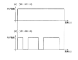
- the codes of the respective sections during the exposure time are all “1” (ON state), and the encoding pattern is ⁇ 111111111 ⁇ .
- the image sensor receives light during the entire exposure time T.
- the code of each section during the exposure time is switched between “1” and “0”.
- the image sensor receives light only in the section of the exposure time T indicated by the symbol “1”.
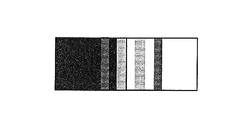
- the encoding pattern is ⁇ 101101110 ⁇ , as shown in FIG. 4B, the ON state and the OFF state are switched during the exposure time.
- FIG. 5 is a schematic diagram of the PSF in the spatial domain. Specifically, FIG. 5A is a diagram illustrating an example of a PSF in the spatial domain when encoding is not performed.
- FIG. 5B is a diagram illustrating an example of a PSF in the spatial domain when encoding is performed.
- FIG. 5 illustrates the PSF in one section cut in the x-axis direction.
- the PSF is converted from FIG. 5A to FIG. 5B by performing encoding.
- FIG. 6 is a schematic diagram of the PSF converted into the frequency domain.
- FIG. 6A is a schematic diagram showing amplitude characteristics when the PSF of FIG. 5A is converted from the spatial domain to the frequency domain.
- FIG. 6B is a schematic diagram showing amplitude characteristics when the PSF of FIG. 5B is converted from the spatial domain to the frequency domain.
- FIG. 6 illustrates the PSF for one section cut in the u-axis direction.
- the PSF obtained by the encoding of FIG. 5B when the PSF obtained by the encoding of FIG. 5B is converted into the frequency domain, the PSF has an amplitude value of 0 unlike the sinc function. not exist. In this way, a PSF whose amplitude value does not become zero at each frequency can be obtained by encoding. By performing the restoration process using the PSF thus obtained, a restored image free from ringing noise can be obtained.
- a PSF whose amplitude value does not become zero in the frequency domain can be obtained by encoding exposure.
- exposure encoding is not performed by blocking light during shooting, but pixel values are changed in each of a plurality of continuously shot input images, and a plurality of changed input images are synthesized. By doing so, exposure encoding is performed. Specifically, encoding is performed by multiplying each input image by L times (where L is a real number from 0 to 1). As described above, in the present embodiment, since it is not necessary to perform shooting that blocks exposure during shooting, various encoding patterns can be selected after shooting.
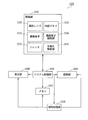
- FIG. 7 is a block diagram showing a functional configuration of the imaging apparatus 100 according to the embodiment of the present invention.
- Imaging device 100 in the present embodiment is a digital electronic camera.
- the imaging apparatus 100 does not necessarily need to be a digital electronic camera.
- the imaging apparatus 100 includes an imaging unit 300, a signal processing unit 200 that performs various signal processing and image restoration processing, a display unit 600 that displays an image, and a recording unit that records image data. 500 and a system control unit 400 that controls each unit.
- the imaging unit 300 continuously captures a plurality of images.
- the imaging unit 300 includes an imaging element (image sensor) 310 including a plurality of photosensitive cells (photodiodes) arranged on the imaging surface, a shutter 325 having a diaphragm function, and imaging of the imaging element 310. And a taking lens 320 for forming an image on the surface.
- the imaging unit 300 includes an internal memory 350 that temporarily stores continuous image data when images are continuously captured (continuous shooting).
- the image sensor 310 is typically a CCD sensor or a CMOS sensor.
- the photographing lens 320 has a known configuration and is generally a lens unit composed of a plurality of lenses.
- the shutter 325 and the photographing lens 320 are driven by a driving mechanism (not shown), and operations necessary for optical zooming, automatic exposure (AE), or autofocus (AF) are executed.
- AE automatic exposure
- AF autofocus
- the imaging unit 300 further includes an imaging element driving unit 330 that drives the imaging element 310.
- the imaging element driving unit 330 is configured by a semiconductor integrated circuit such as a CCD driver, for example.
- the image sensor driving unit 330 drives the image sensor 310 to read out analog signals (photoelectric conversion signals) from the image sensor 310 and convert them into digital signals.
- the imaging unit 300 further includes a camera shake detection unit 345 that detects a camera shake during shooting.
- the camera shake detection unit 345 is, for example, a known gyroscope or acceleration sensor.
- the camera shake detection unit 345 detects the movement of the imaging apparatus 100 during the exposure time, and generates information (camera shake information) indicating the locus of camera shake.
- the generated camera shake information is input to the signal processing unit 200, and is used for the process of acquiring the first PSF used in the image restoration process.
- the signal processing unit 200 performs a degraded image restoration process. That is, the signal processing unit 200 reduces blurring that occurs in an image obtained by combining a plurality of continuously captured input images.
- the signal processing unit 200 may perform various signal processing such as color tone correction, resolution change, or data compression. Details of the degraded image restoration processing in the signal processing unit 200 will be described later with reference to FIG.
- the signal processing unit 200 is preferably realized by a combination of hardware such as a known digital signal processor (DSP) and software for executing image processing.
- DSP digital signal processor
- the memory 240 is configured by DRAM (Dynamic Random Access Memory) or the like.
- the memory 240 records the image data obtained from the imaging unit 300 and temporarily stores the image data subjected to various image processing by the signal processing unit 200 and the compressed image data.
- the image data is converted into an analog signal and then displayed on the display unit 600 or recorded in the recording unit 500 as a digital signal.
- the image data may be transmitted to another device (not shown) wirelessly or via a communication device (not shown).
- the system control unit 400 controls the imaging unit 300, the signal processing unit 200, the memory 240, the recording unit 500, and the display unit 600.
- the system control unit 400 includes a central processing unit (CPU: Central Processing Unit) (not shown) and a flash memory.
- CPU Central Processing Unit
- the imaging apparatus of the present embodiment may include known components such as an optical finder, a power source (battery), and a flashlight, but a description thereof is omitted because it is not particularly necessary for understanding the present invention.
- FIG. 8 is a block diagram showing a functional configuration of the signal processing unit 200 according to the embodiment of the present invention.
- the signal processing unit 200 includes an image input unit 1100, a PSF acquisition unit 1200, a PSF conversion unit 1300, an image conversion unit 1400, an image restoration unit 1500, and an image output unit 1600.
- the image input unit 1100 acquires a plurality of input images continuously captured by the imaging unit 300.
- the PSF acquisition unit 1200 acquires a first PSF indicating blurring occurring over a plurality of input images acquired by the image input unit 1100 based on sensor information such as a gyro sensor and an acceleration sensor. Specifically, the PSF acquisition unit 1200 calculates the first PSF using, for example, camera shake information detected by the camera shake detection unit 345 when a plurality of input images are captured.
- the PSF conversion unit 1300 converts the first PSF obtained from the PSF acquisition unit 1200 into a second PSF. Specifically, the PSF conversion unit 1300 generates the second PSF by processing the first PSF so that the amplitude value of each frequency does not become less than the threshold value in the frequency domain. That is, the PSF conversion unit 1300 generates a second PSF in which the amplitude value of each frequency is greater than or equal to the threshold value in the frequency domain based on the first PSF.
- the image conversion unit 1400 converts each of the plurality of input images acquired by the image input unit 1100 based on the second PSF. Specifically, the image conversion unit 1400 generates a plurality of converted images by converting each of the plurality of input images using a portion corresponding to each input image in the second PSF.
- the image restoration unit 1500 generates a restored image by performing restoration processing using the second PSF on a degraded image (encoded degraded image) obtained by combining a plurality of converted images. Note that an image obtained by combining a plurality of converted images is obtained by adding pixel values for each pixel position of the pixels constituting each converted image.
- the image output unit 1600 outputs the generated restored image.
- the image output unit 1600 outputs the restored image to at least one of the recording unit 500 and the display unit 600, for example.
- the configuration of the signal processing unit 200 illustrated in FIG. 8 is an example, and the signal processing unit 200 may be divided into other functional blocks.
- the signal processing unit 200 is preferably realized by, for example, incorporating image processing software into known hardware.
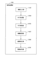
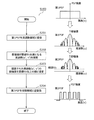
- FIG. 9 is a flowchart showing a flow of a degraded image restoration process in the signal processing unit 200 according to the embodiment of the present invention.
- FIG. 10 is a flowchart showing the flow of PSF conversion processing in the PSF conversion unit 1300 according to the embodiment of the present invention.
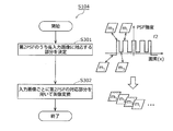
- FIG. 11 is a flowchart showing a flow of image conversion processing in the image conversion unit 1400 according to the embodiment of the present invention.
- the image input unit 1100 continuously captures images in the imaging unit 300 and is stored in the internal memory 350 of the imaging unit 300 (n sheets: n is an integer of 2 or more) input images m i (x, y) ( i is an integer from 1 to n) (S101).
- the PSF acquisition unit 1200 acquires camera shake information detected by the camera shake detection unit 345 when a plurality of input images are captured. Furthermore, the PSF acquisition unit 1200 generates a degraded image by adding the pixel values of the acquired plurality of input images for each pixel position. Then, the PSF acquisition unit 1200 acquires a first PSF (f1 (x, y)) indicating blurring that occurs across a plurality of input images based on the camera shake information and the deteriorated image (S102).
- the PSF acquisition unit 1200 is not necessarily required to acquire the first PSF based on both the camera shake information and the degraded image.
- the PSF acquisition unit 1200 may acquire the first PSF based only on the camera shake information among the camera shake information and the deteriorated image.
- the PSF acquisition unit 1200 can acquire the first PSF that shows both the shake of the subject and the camera shake by acquiring the first PSF using the PSF calculated by the signal processing using the degraded image. .
- the PSF conversion unit 1300 generates the second PSF by processing the first PSF so that the amplitude value of each frequency does not become less than the threshold value in the frequency domain (S103). Specifically, the PSF conversion unit 1300 performs the process shown in FIG.
- the PSF conversion unit 1300 first calculates an amplitude value for each frequency by converting the first PSF acquired by the PSF acquisition unit 1200 from the spatial domain to the frequency domain (S201).
- the first PSF in the spatial domain is represented as f1 (x, y)
- the first PSF in the frequency domain is represented as F1 (u, v).
- the PSF conversion unit 1300 identifies the frequency (u ′, v ′) at which the amplitude value of the first PSF is less than the threshold fth (
- the PSF conversion unit 1300 generates the second PSF by changing the amplitude value to a predetermined value equal to or higher than the threshold fth at the specified frequency (u ′, v ′) (S203).
- the second PSF generated here is the second PSF in the frequency domain, and is represented as F2 (u, v).
- the PSF conversion unit 1300 inversely converts F2 (u, v) from the frequency domain to the spatial domain (S204).
- the second PSF converted into the spatial domain is represented as f2 (x, y).
- the second PSF obtained in this way has no zero point in the frequency domain. Therefore, ringing noise does not occur in the restored image obtained by the restoration process using the second PSF.
- the image conversion unit 1400 generates a converted image by converting each of the plurality of input images using a portion corresponding to each input image in the second PSF (S104). Specifically, the image conversion unit 1400 performs the process shown in FIG.
- the image conversion unit 1400 determines a portion of the second PSF corresponding to each input image in time based on the time when the blur indicated by the second PSF is detected and the time when each input image is captured. (S301). Specifically, the image conversion unit 1400 determines, for example, a pixel (for example, one pixel) showing a blur corresponding to the input image in time among the plurality of pixels constituting the second PSF as a portion corresponding to the input image. .
- the image conversion unit 1400 converts each of the plurality of input images using a portion corresponding to each input image (S302). Specifically, the image conversion unit 1400 converts the input image m i (x, y) into the converted image m i ′ (x, y) according to the following (Equation 7). For example, as shown in (Equation 7), the image conversion unit 1400 generates a converted image by convolution of the input image and the second PSF corresponding to the input image. In (Expression 7), f2 i (x, y) indicates a portion of the second PSF corresponding to the input image m i (x, y).
- the image restoration unit 1500 generates a restored image by performing restoration processing using the second PSF on the degraded image s ′ (x, y) (S105).
- the deteriorated image s ′ (x, y) is an image obtained by simply synthesizing the converted image m i ′ (x, y), and is obtained by the following (Equation 8).
- the deteriorated image s ′ (x, y) corresponds to a deteriorated image encoded so that no zero point is generated in the PSF.
- the algorithm of the restoration process executed by the image restoration unit 1500 is not particularly limited, and any known image restoration process may be used.
- the image restoration unit 1500 can execute the restoration process using, for example, a known Richardson Lucy (LR) method or a Wiener filter method. Further, the image restoration unit 1500 may perform the restoration process using the sparse coding method disclosed in Non-Patent Document 1.
- the image restoration unit 1500 may generate the restored image r (x, y) by the following (Equation 9) in the simplest case.
- R (u, v) and S ′ (u, v) indicate a restored image and an encoded degraded image that have been converted to the frequency domain. That is, a restored image r (x, y) is obtained by inversely transforming R (u, v) calculated by (Equation 9) into a spatial domain.
- the image output unit 1600 outputs the restored image obtained as described above (S106), and ends the process.
- the restored image is recorded in the recording unit 500 or displayed on the display unit 600, for example.
- FIG. 12 is a diagram illustrating an example of an ideal image.
- FIG. 13 is a diagram illustrating an example of frequency characteristics of an ideal image.
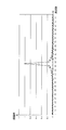
- FIG. 14 is a diagram illustrating an example of the first PSF.
- FIG. 15 is a diagram illustrating an example of frequency characteristics of the first PSF.
- FIG. 16 is a diagram illustrating an example of a deteriorated image.
- FIG. 17 is a diagram illustrating an example of frequency characteristics of a deteriorated image.
- the signal shown in FIG. 12 was set as an image signal (ideal image) with no camera shake.
- the horizontal axis indicates the pixel number in the x-axis direction
- the vertical axis indicates the pixel value.
- the first PSF was set as shown in FIG.
- the horizontal axis indicates the pixel number in the x-axis direction
- the vertical axis indicates the PSF intensity.
- FIGS. 13, 15 and 17 show frequency characteristics when the images or PSFs shown in FIGS. 12, 14 and 16 are converted into the frequency domain.
- the horizontal axis indicates the spatial frequency in the u-axis direction
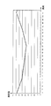
- the vertical axis indicates the amplitude value. From the frequency characteristics of the first PSF shown in FIG. 15, it can be seen that the first PSF has a spatial frequency (zero point) at which the amplitude value is zero in the frequency domain.
- the simplest image restoration method is the method shown in (Formula 5). Therefore, in this simulation, the image restoration method according to (Equation 5) is treated as a conventional image restoration method.
- FIG. 18 is a diagram illustrating an example of a restored image obtained by a conventional image restoration method.
- the restored image shown in FIG. 18 is an image obtained by dividing the frequency component of the degraded image shown in FIG. 17 for each frequency using the frequency component of the first PSF shown in the drawing.
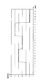
- FIG. 19 is a diagram illustrating an example of the second PSF.
- FIG. 20 is a diagram illustrating an example of frequency characteristics of the second PSF.
- FIG. 21 is a diagram showing an example of a restored image obtained by the image restoration method according to the embodiment of the present invention.
- the PSF conversion unit 1300 refers to the frequency characteristic of the first PSF shown in FIG. 15 and searches for a frequency whose amplitude value is smaller than the threshold fth.
- the threshold value fth is set to “0.001”.
- the PSF conversion unit 1300 calculates the second PSF by changing the amplitude value of the searched frequency to the predetermined value pv.
- the predetermined value pv is set to “0.5”.
- the second PSF shown in FIG. 19 is obtained by inversely transforming the second PSF shown in FIG. 20 from the frequency domain to the spatial domain.
- the second PSF can be a negative value unlike the conventional case.
- the PSF value represented by 0 to 1 is temporarily set by encoding. It is set to 0. That is, a method has been shown in which the amplitude value does not become zero in the frequency domain by partially setting the PSF whose sum is 1 to 0 (that is, by reducing the amount of light). In the present embodiment, by multiplying the PSF by a real number, the ringing can be eliminated while the total sum of the PSFs indicating the entire light quantity remains at 1.
- the image conversion unit 1400 generates a plurality of converted images by performing conversion processing on each of the plurality of input images using a portion corresponding to each input image in the second PSF shown in FIG.
- a deteriorated image obtained by combining a plurality of converted images generated in this way corresponds to a deteriorated image obtained when encoded.
- the image restoration unit 1500 generates a restored image by performing restoration processing using the degraded image obtained by combining the plurality of converted images and the second PSF shown in FIG. FIG. 21 shows a restored image generated in this way.
- the restored image obtained by the image restoration method according to the present embodiment is the same as the ideal image shown in FIG. From this, it can be confirmed that the image restoration method according to the present embodiment can generate a restored image without ringing.
- the threshold value fth and the predetermined value pv are not necessarily these values. If the predetermined value pv is increased, the amplitude value of the specific frequency increases, and thus the PSF intensity of the second PSF at the specific frequency is amplified. In an extreme example, the PSF intensity of the second PSF may be strongly amplified only at one frequency.
- the luminance of one specific input image among the plurality of input images is amplified, and the luminance of the other input images is attenuated to generate an encoded degraded image.
- Each of the plurality of input images has no blur but the image brightness is dark. Therefore, if the luminance of the input image is excessively amplified, noise will increase. Therefore, it is not preferable to make the predetermined value pv too large.
- the threshold value fth is increased, the absolute value (PSF intensity) of the second PSF in each pixel increases. As a result, the amount of amplification of the pixel value of each input image increases. Therefore, it is not desirable to make the threshold fth too large.
- the PSF conversion unit 1300 searches for the second PSF in which the PSF intensity is not excessively large while changing the predetermined value pv and the threshold value fth. Specifically, the PSF conversion unit 1300 temporarily sets the predetermined value pv and the threshold value fth, and repeats checking whether the PSF intensity of the second PSF is excessively large, thereby repeating the PSF of the second PSF. It is preferable to search for the predetermined value pv and the threshold value fth when the intensity does not become excessively large. Even if the predetermined value pv and the threshold value fth are searched for in this way, it is not necessary to repeat the restoration process using the PSF as in the conventional non-patent document 7, so that an increase in the amount of calculation is suppressed.
- the predetermined value pv and the threshold value fth are constant values in the entire frequency band, but are not necessarily constant values.
- Ringing noise is considered to be noise that appears in a flat part (low frequency component) of an image. Therefore, the predetermined value pv and the threshold value fth are preferably set so that the value increases as the frequency decreases. That is, the predetermined value pv used when changing the amplitude value of the first frequency is larger than the predetermined value pv used when changing the amplitude value of the second frequency, which is a higher frequency than the first frequency. preferable. Moreover, it is preferable that the threshold value fth used when specifying the first frequency is larger than the threshold value fth used when specifying the second frequency that is higher than the first frequency. Thereby, it is possible to efficiently reduce ringing noise which is noise generated in a low frequency portion.
- the signal processing unit 200 can make the low-frequency amplitude value larger than the high-frequency amplitude value at the frequency at which the amplitude value is changed by changing the predetermined value pv according to the frequency. Therefore, the signal processing unit 200 can efficiently reduce ringing noise that is noise generated in a low frequency region.
- the signal processing unit 200 can efficiently eliminate a small amplitude value that causes ringing noise in the low frequency region by changing the threshold fth according to the frequency. Therefore, the signal processing unit 200 can efficiently reduce ringing noise that is noise generated in a low frequency region.
- the threshold value fth and the predetermined value pv may be set in consideration of the nature of the input image.
- the numerator is the frequency component of the degraded image
- the denominator is the frequency component of the second PSF.
- the threshold fth and the predetermined value pv are set as small as possible at a frequency where the amplitude value of the degraded image is 0 in the frequency domain.
- the threshold value fth and the predetermined value pv may be determined according to the noise amount of the input image. That is, the threshold value fth and the predetermined value pv may be determined by the S / N ratio of the input image. Specifically, the threshold fth and the predetermined value pv are preferably values determined so as to decrease as the noise generated in the input image increases.
- the PSF conversion unit 1300 stores a combination of a threshold value fth corresponding to the brightness of the shooting scene and a predetermined value pv in a memory, and a threshold value corresponding to the brightness measured when the input image is shot.
- the threshold fth and the predetermined value pv may be determined by reading a combination of fth and the predetermined value pv from the memory.
- the brighter the shooting scene the smaller the noise.
- the PSF conversion unit 1300 determines the threshold value fth and the predetermined value pv using shooting conditions (for example, ISO sensitivity) or the S / N ratio in the input image instead of the brightness of the shooting scene. Also good.
- the signal processing unit 200 changes the amplitude value, thereby causing noise in the restored image.
- the adverse effect of being amplified can be suppressed.
- the imaging apparatus 100 processes the first PSF indicating the blur generated over a plurality of input images, so that the amplitude value of each frequency in the frequency domain is greater than or equal to the threshold value. 2PSF is generated. Then, the imaging apparatus 100 converts each input image using each part of the second PSF. An image obtained by synthesizing a plurality of input images thus converted corresponds to a deteriorated image that is encoded so that a zero point does not occur in the PSF. That is, the imaging apparatus 100 can generate a deteriorated image that is encoded so that no zero point is generated in the PSF, by adapting to a blur that occurs over a plurality of input images.
- the imaging apparatus 100 since the imaging apparatus 100 does not need to determine a coding pattern in advance, the occurrence of ringing can be stably suppressed. Furthermore, the imaging apparatus 100 does not need to repeat the restoration process in order to generate a deteriorated image that is encoded so that no zero point occurs in the PSF. Therefore, the imaging apparatus 100 can also suppress an increase in processing load.
- the imaging apparatus 100 generates the second PSF by changing the amplitude value at a frequency at which the amplitude value of the first PSF is less than the threshold value. Therefore, the imaging apparatus 100 can generate an encoded deteriorated image that is adapted to blurring that occurs over a plurality of input images. That is, the imaging apparatus 100 can generate a restored image with less blur.
- the imaging device 100 has been described based on the embodiments.
- the present invention is not limited to these embodiments. As long as it does not deviate from the gist of the present invention, forms in which various modifications conceived by those skilled in the art have been made in this embodiment are also included in the scope of the present invention.
- the PSF conversion unit 1300 generates the second PSF by changing the amplitude value of the first PSF to a predetermined value, but may generate the second PSF by other methods.
- the PSF conversion unit 1300 generates an offset PSF in which the amplitude value of the specified frequency is equal to or greater than a threshold, and generates the second PSF by adding the offset PSF and the first PSF in the frequency domain.
- the offset PSF is, for example, a function in which only the amplitude value of the specified frequency becomes a constant value equal to or greater than the threshold value, and the amplitude values of other frequencies become zero.
- the PSF conversion unit 1300 changes the amplitude value only at the frequency at which the amplitude value of the first PSF is less than the threshold value, but the amplitude is also at the frequency at which the amplitude value of the first PSF is equal to or greater than the threshold value.
- the value may be changed.
- the PSF conversion unit 1300 may change the amplitude value so that the change in the amplitude value is smooth in the vicinity of the frequency at which the amplitude value of the first PSF is less than the threshold value.
- the present invention may be realized as an image restoration device including a characteristic processing unit included in the signal processing unit 200.
- the image restoration device 10 may be configured as shown in FIG. 22, for example.
- FIG. 22 is a block diagram illustrating a functional configuration of the image restoration apparatus 10 according to an aspect of the present invention.
- the image restoration apparatus 10 illustrated in FIG. 22 includes a PSF acquisition unit 1200, a PSF conversion unit 1300, an image conversion unit 1400, and an image restoration unit 1500. Similar to the signal processing unit 200, the image restoration apparatus 10 uses a plurality of input images obtained by successively converting a deteriorated image encoded so that a zero point does not occur in the PSF. Can be adapted to the blur occurring over the entire time. Therefore, the image restoration apparatus 10 can stably suppress the occurrence of ringing while suppressing an increase in processing load.
- the image restoration apparatus 10 may include a system LSI 20 having a PSF acquisition unit 1200, a PSF conversion unit 1300, an image conversion unit 1400, and an image restoration unit 1500.
- LSI Large Scale Integration
- the image restoration apparatus 10 may include a system LSI 20 having a PSF acquisition unit 1200, a PSF conversion unit 1300, an image conversion unit 1400, and an image restoration unit 1500.
- the system LSI 20 is an ultra-multifunctional LSI manufactured by integrating a plurality of components on one chip. Specifically, a microprocessor, a ROM (Read Only Memory), a RAM (Random Access Memory), etc. It is a computer system comprised including. A computer program is stored in the RAM. The system LSI achieves its functions by the microprocessor operating according to the computer program.
- system LSI may be called IC, LSI, super LSI, or ultra LSI depending on the degree of integration.
- method of circuit integration is not limited to LSI's, and implementation using dedicated circuitry or general purpose processors is also possible.
- An FPGA Field Programmable Gate Array
- reconfigurable processor that can reconfigure the connection and setting of circuit cells inside the LSI may be used.
- the present invention can be realized not only as an image restoration apparatus including such a characteristic processing unit, but also as an image restoration method using the characteristic processing unit included in the image restoration apparatus as a step. You can also. It can also be realized as a computer program that causes a computer to execute the characteristic steps included in the image restoration method. Needless to say, such a computer program can be distributed via a computer-readable recording medium such as a CD-ROM or a communication network such as the Internet.
- An image restoration device can generate an image with less blur even when camera shake occurs or an object moves during image shooting, and can be used as a digital camera, movie, or surveillance camera. Useful as such.
- image restoration device 20 system LSI DESCRIPTION OF SYMBOLS 100 Imaging device 200 Signal processing part 240 Memory 300 Imaging part 310 Imaging element 320 Shooting lens 325 Shutter 330 Imaging element drive part 345 Camera shake detection part 350 Internal memory 500 Recording part 600 Display part 1100 Image input part 1200 PSF acquisition part 1300 PSF conversion part 1400 Image conversion unit 1500 Image restoration unit 1600 Image output unit
Landscapes
- Engineering & Computer Science (AREA)
- Multimedia (AREA)
- Signal Processing (AREA)
- Physics & Mathematics (AREA)
- General Physics & Mathematics (AREA)
- Theoretical Computer Science (AREA)
- Image Processing (AREA)
- Studio Devices (AREA)
- Facsimile Image Signal Circuits (AREA)
Abstract
Description









20 システムLSI
100 撮像装置
200 信号処理部
240 メモリ
300 撮像部
310 撮像素子
320 撮影レンズ
325 シャッタ
330 撮像素子駆動部
345 手振れ検出部
350 内部メモリ
500 記録部
600 表示部
1100 画像入力部
1200 PSF取得部
1300 PSF変換部
1400 画像変換部
1500 画像復元部
1600 画像出力部
Claims (11)
- 連続して撮影された複数の入力画像が合成された画像に発生するブレを低減させる画像復元装置であって、
前記複数の入力画像にわたって発生しているブレを示す第1PSF(Point Spread Function)を取得するPSF取得部と、
周波数領域において各周波数の振幅値が閾値未満とならないように前記第1PSFを加工することにより第2PSFを生成するPSF変換部と、
前記第2PSFのうち各入力画像に対応する部分を用いて前記複数の入力画像をそれぞれ変換することにより、複数の変換画像を生成する画像変換部と、
前記複数の変換画像が合成された劣化画像に対して、前記第2PSFを用いた復元処理を施すことにより、復元画像を生成する画像復元部とを備える
画像復元装置。 - 前記PSF変換部は、周波数領域において前記第1PSFの振幅値が前記閾値未満である周波数を特定し、特定した前記周波数において振幅値を前記閾値以上の所定値に変更することにより、前記第1PSFを加工する
請求項1に記載の画像復元装置。 - 第1周波数の振幅値を変更するときに用いられる前記所定値は、前記第1周波数よりも高い周波数である第2周波数の振幅値を変更するときに用いられる前記所定値よりも大きい
請求項2に記載の画像復元装置。 - 前記所定値は、前記入力画像に生じているノイズが大きいほど小さくなるように決定された値である
請求項2に記載の画像復元装置。 - 第1周波数を特定するときに用いられる前記閾値は、前記第1周波数よりも高い周波数である第2周波数を特定するときに用いられる前記閾値よりも大きい
請求項2に記載の画像復元装置。 - 前記閾値は、前記入力画像に生じているノイズが大きいほど小さくなるように決定された値である
請求項2に記載の画像復元装置。 - 前記画像変換部は、前記第2PSFが示すブレが検出された時間と、前記各入力画像が撮影された時間とに基づいて、前記第2PSFのうち各入力画像に時間的に対応する部分を決定し、決定した部分を用いて前記複数の入力画像をそれぞれ変換する
請求項1に記載の画像復元装置。 - 前記PSF変換部は、周波数領域において前記第1PSFの振幅値が前記閾値未満である周波数を特定し、特定した前記周波数の振幅値が前記閾値以上であるオフセットPSFを生成し、前記オフセットPSFと前記第1PSFとを加算することにより、前記第2PSFを生成する
請求項1に記載の画像復元装置。 - 連続して撮影された複数の入力画像が合成された画像に発生するブレを低減させる集積回路であって、
前記複数の入力画像にわたって発生しているブレを示す第1PSF(Point Spread Function)を取得するPSF取得部と、
周波数領域において各周波数の振幅値が閾値未満とならないように前記第1PSFを加工することにより第2PSFを生成するPSF変換部と、
前記第2PSFのうち各入力画像に対応する部分を用いて前記複数の入力画像をそれぞれ変換することにより、複数の変換画像を生成する画像変換部と、
前記複数の変換画像が合成された劣化画像に対して、前記第2PSFを用いた復元処理を施すことにより、復元画像を生成する画像復元部とを備える
集積回路。 - 連続して撮影された複数の入力画像が合成された画像に発生するブレを低減させる画像復元方法であって、
前記複数の入力画像にわたって発生しているブレを示す第1PSF(Point Spread Function)を取得するPSF取得ステップと、
周波数領域において各周波数の振幅値が閾値未満とならないように前記第1PSFを加工することにより第2PSFを生成するPSF変換ステップと、
前記第2PSFのうち各入力画像に対応する部分を用いて前記複数の入力画像をそれぞれ変換することにより、複数の変換画像を生成する画像変換ステップと、
前記複数の変換画像が合成された劣化画像に対して、前記第2PSFを用いた復元処理を施すことにより、復元画像を生成する画像復元ステップとを含む
画像復元方法。 - 請求項10に記載の画像復元方法をコンピュータに実行させるためのプログラム。
Priority Applications (2)
| Application Number | Priority Date | Filing Date | Title |
|---|---|---|---|
| US13/499,733 US8600187B2 (en) | 2010-08-05 | 2011-08-04 | Image restoration apparatus and image restoration method |
| CN201180004125.6A CN102687500B (zh) | 2010-08-05 | 2011-08-04 | 图像恢复装置以及图像恢复方法 |
Applications Claiming Priority (2)
| Application Number | Priority Date | Filing Date | Title |
|---|---|---|---|
| JP2010176790A JP5204165B2 (ja) | 2010-08-05 | 2010-08-05 | 画像復元装置および画像復元方法 |
| JP2010-176790 | 2010-08-05 |
Publications (1)
| Publication Number | Publication Date |
|---|---|
| WO2012017662A1 true WO2012017662A1 (ja) | 2012-02-09 |
Family
ID=45559181
Family Applications (1)
| Application Number | Title | Priority Date | Filing Date |
|---|---|---|---|
| PCT/JP2011/004426 Ceased WO2012017662A1 (ja) | 2010-08-05 | 2011-08-04 | 画像復元装置および画像復元方法 |
Country Status (4)
| Country | Link |
|---|---|
| US (1) | US8600187B2 (ja) |
| JP (1) | JP5204165B2 (ja) |
| CN (1) | CN102687500B (ja) |
| WO (1) | WO2012017662A1 (ja) |
Families Citing this family (19)
| Publication number | Priority date | Publication date | Assignee | Title |
|---|---|---|---|---|
| JP5543280B2 (ja) | 2010-06-01 | 2014-07-09 | キヤノン株式会社 | 画像処理装置、画像処理方法 |
| JP5656705B2 (ja) * | 2010-06-01 | 2015-01-21 | キヤノン株式会社 | 撮像装置、撮像装置の制御方法 |
| US8861884B1 (en) | 2011-11-21 | 2014-10-14 | Google Inc. | Training classifiers for deblurring images |
| WO2013144427A1 (en) * | 2012-03-26 | 2013-10-03 | Nokia Corporation | Method, apparatus and computer program product for image stabilization |
| WO2014136323A1 (ja) * | 2013-03-04 | 2014-09-12 | 富士フイルム株式会社 | 復元フィルタ生成装置及び方法、画像処理装置、撮像装置、復元フィルタ生成プログラム並びに記録媒体 |
| JP5833794B2 (ja) * | 2013-03-27 | 2015-12-16 | 富士フイルム株式会社 | 撮像装置 |
| US10128944B2 (en) * | 2013-05-24 | 2018-11-13 | Philips Lighting Holding B.V. | Detecting coded light |
| CN104932868B (zh) * | 2014-03-17 | 2019-01-15 | 联想(北京)有限公司 | 一种数据处理方法及电子设备 |
| JP2015195439A (ja) * | 2014-03-31 | 2015-11-05 | ソニー株式会社 | 画像処理装置、画像処理方法及びプログラム |
| JP6350205B2 (ja) * | 2014-10-21 | 2018-07-04 | 富士通株式会社 | 処理装置、処理方法および処理プログラム |
| CN104539825B (zh) * | 2014-12-18 | 2018-04-13 | 北京智谷睿拓技术服务有限公司 | 信息发送、接收方法及装置 |
| US20160259758A1 (en) * | 2015-03-04 | 2016-09-08 | Animesh Khemka | Digital Camera Simulation Using Spatially Varying PSF Convolutions |
| CN105956240B (zh) * | 2016-04-25 | 2019-05-17 | 北京航空航天大学 | 一种用于宽带电磁分布探测的点扩展函数估计方法 |
| CN110249619B (zh) * | 2017-02-17 | 2021-04-20 | 富士胶片株式会社 | 图像处理装置、图像处理方法及相机系统 |
| WO2018150695A1 (ja) * | 2017-02-17 | 2018-08-23 | 富士フイルム株式会社 | 画像処理装置、画像処理方法、およびカメラシステム |
| WO2020061856A1 (en) * | 2018-09-26 | 2020-04-02 | Guangdong Oppo Mobile Telecommunications Corp., Ltd. | Method and device for recovering image passing through display |
| CN110062164B (zh) * | 2019-04-22 | 2021-10-26 | 深圳市商汤科技有限公司 | 视频图像处理方法及装置 |
| CN112950482B (zh) * | 2019-12-10 | 2023-05-26 | 深圳大学 | 物体信息恢复方法、装置、计算机设备和存储介质 |
| CN116704935B (zh) * | 2023-06-15 | 2025-12-02 | 湖北长江新型显示产业创新中心有限公司 | 补偿数据的确定方法、亮度补偿方法、装置及存储介质 |
Citations (4)
| Publication number | Priority date | Publication date | Assignee | Title |
|---|---|---|---|---|
| JP2008310797A (ja) * | 2007-06-12 | 2008-12-25 | Mitsubishi Electric Research Laboratories Inc | カメラによって或るシーンから取得される画像内の動いている物体の解像度を高めるための方法 |
| JP2009033292A (ja) * | 2007-07-25 | 2009-02-12 | Eastman Kodak Co | 画像処理システム、撮像装置及び出力装置 |
| JP2009522825A (ja) * | 2006-05-08 | 2009-06-11 | ミツビシ・エレクトリック・リサーチ・ラボラトリーズ・インコーポレイテッド | シーンの画像におけるぶれを低減する方法及びシーンの画像のぶれを除去する方法 |
| JP2011109619A (ja) * | 2009-11-20 | 2011-06-02 | Canon Inc | 画像処理方法および画像処理装置、プログラム |
Family Cites Families (9)
| Publication number | Priority date | Publication date | Assignee | Title |
|---|---|---|---|---|
| JP2001197357A (ja) | 2000-01-12 | 2001-07-19 | Hitachi Ltd | 撮像装置 |
| JP2006129236A (ja) | 2004-10-29 | 2006-05-18 | Sanyo Electric Co Ltd | リンギング除去装置およびリンギング除去プログラムを記録したコンピュータ読み取り可能な記録媒体 |
| JP4469309B2 (ja) * | 2005-06-22 | 2010-05-26 | 株式会社リコー | 手ぶれ補正方法、手ぶれ補正装置、及び撮像装置 |
| JP2007193508A (ja) * | 2006-01-18 | 2007-08-02 | Sanyo Electric Co Ltd | 画像処理装置及び画像処理プログラム |
| US7639289B2 (en) | 2006-05-08 | 2009-12-29 | Mitsubishi Electric Research Laboratories, Inc. | Increasing object resolutions from a motion-blurred image |
| US7756407B2 (en) | 2006-05-08 | 2010-07-13 | Mitsubishi Electric Research Laboratories, Inc. | Method and apparatus for deblurring images |
| US20080144900A1 (en) * | 2006-10-23 | 2008-06-19 | Northwestern University | Fast self-calibrating radial sensitivity encoded image reconstruction using rescaling and preconditioning |
| JP2009267523A (ja) * | 2008-04-22 | 2009-11-12 | Nikon Corp | 画像復元装置及び撮像装置 |
| US8886206B2 (en) * | 2009-05-01 | 2014-11-11 | Digimarc Corporation | Methods and systems for content processing |
-
2010
- 2010-08-05 JP JP2010176790A patent/JP5204165B2/ja not_active Expired - Fee Related
-
2011
- 2011-08-04 CN CN201180004125.6A patent/CN102687500B/zh not_active Expired - Fee Related
- 2011-08-04 US US13/499,733 patent/US8600187B2/en not_active Expired - Fee Related
- 2011-08-04 WO PCT/JP2011/004426 patent/WO2012017662A1/ja not_active Ceased
Patent Citations (4)
| Publication number | Priority date | Publication date | Assignee | Title |
|---|---|---|---|---|
| JP2009522825A (ja) * | 2006-05-08 | 2009-06-11 | ミツビシ・エレクトリック・リサーチ・ラボラトリーズ・インコーポレイテッド | シーンの画像におけるぶれを低減する方法及びシーンの画像のぶれを除去する方法 |
| JP2008310797A (ja) * | 2007-06-12 | 2008-12-25 | Mitsubishi Electric Research Laboratories Inc | カメラによって或るシーンから取得される画像内の動いている物体の解像度を高めるための方法 |
| JP2009033292A (ja) * | 2007-07-25 | 2009-02-12 | Eastman Kodak Co | 画像処理システム、撮像装置及び出力装置 |
| JP2011109619A (ja) * | 2009-11-20 | 2011-06-02 | Canon Inc | 画像処理方法および画像処理装置、プログラム |
Also Published As
| Publication number | Publication date |
|---|---|
| JP5204165B2 (ja) | 2013-06-05 |
| US8600187B2 (en) | 2013-12-03 |
| US20120195520A1 (en) | 2012-08-02 |
| CN102687500A (zh) | 2012-09-19 |
| CN102687500B (zh) | 2016-04-06 |
| JP2012039326A (ja) | 2012-02-23 |
Similar Documents
| Publication | Publication Date | Title |
|---|---|---|
| JP5204165B2 (ja) | 画像復元装置および画像復元方法 | |
| CN102907082B (zh) | 摄像装置、图像处理装置、图像处理方法 | |
| US8654201B2 (en) | Method for deblurring an image | |
| US8390704B2 (en) | Image deblurring using a spatial image prior | |
| JP5237978B2 (ja) | 撮像装置および撮像方法、ならびに前記撮像装置のための画像処理方法 | |
| CN101331754B (zh) | 成像设备和成像方法 | |
| US8588541B2 (en) | Method and device for image deblurring using joint bilateral filtering | |
| CN102428694B (zh) | 摄像装置以及图像处理装置 | |
| TWI382754B (zh) | 調整模糊影像的方法 | |
| JPWO2011099244A1 (ja) | 画像処理装置および画像処理方法 | |
| US8855416B2 (en) | Image processing method and image processing apparatus | |
| KR100793284B1 (ko) | 디지털 영상의 손떨림 보정 장치, 방법 및 상기 방법을프로그램화하여 수록한 컴퓨터로 읽을 수 있는 기록매체 | |
| WO2010093040A1 (ja) | モーションブラー制御装置、方法、及びプログラム | |
| JP5184574B2 (ja) | 撮像装置、画像処理装置、および画像処理方法 | |
| JP5765893B2 (ja) | 画像処理装置、撮像装置および画像処理プログラム | |
| US8649626B2 (en) | Image processing apparatus and method | |
| JP2012085205A (ja) | 画像処理装置、撮像装置、画像処理方法および画像処理プログラム | |
| Luo et al. | Real‐time digital image stabilization for cell phone cameras in low‐light environments without frame memory | |
| JP2009153046A (ja) | ぶれ補正装置及び方法並びに撮像装置 | |
| WO2024129062A1 (en) | Method and apparatus for unified multi-stage artificial intelligence-based image signal processing pipeline | |
| Deever | Improved image capture using liveview images | |
| Sawada et al. | A study of blind image restoration by fast image deconvolution utilizing hyper-laplacian prior |
Legal Events
| Date | Code | Title | Description |
|---|---|---|---|
| WWE | Wipo information: entry into national phase |
Ref document number: 201180004125.6 Country of ref document: CN |
|
| WWE | Wipo information: entry into national phase |
Ref document number: 13499733 Country of ref document: US |
|
| 121 | Ep: the epo has been informed by wipo that ep was designated in this application |
Ref document number: 11814297 Country of ref document: EP Kind code of ref document: A1 |
|
| NENP | Non-entry into the national phase |
Ref country code: DE |
|
| 122 | Ep: pct application non-entry in european phase |
Ref document number: 11814297 Country of ref document: EP Kind code of ref document: A1 |