WO2012015061A1 - 結晶配向セラミックス及びその製造方法 - Google Patents
結晶配向セラミックス及びその製造方法 Download PDFInfo
- Publication number
- WO2012015061A1 WO2012015061A1 PCT/JP2011/067605 JP2011067605W WO2012015061A1 WO 2012015061 A1 WO2012015061 A1 WO 2012015061A1 JP 2011067605 W JP2011067605 W JP 2011067605W WO 2012015061 A1 WO2012015061 A1 WO 2012015061A1
- Authority
- WO
- WIPO (PCT)
- Prior art keywords
- bonding interface
- sio
- mainly composed
- oriented
- layer mainly
- Prior art date
- Legal status (The legal status is an assumption and is not a legal conclusion. Google has not performed a legal analysis and makes no representation as to the accuracy of the status listed.)
- Ceased
Links
Images









Classifications
-
- C—CHEMISTRY; METALLURGY
- C01—INORGANIC CHEMISTRY
- C01B—NON-METALLIC ELEMENTS; COMPOUNDS THEREOF; METALLOIDS OR COMPOUNDS THEREOF NOT COVERED BY SUBCLASS C01C
- C01B33/00—Silicon; Compounds thereof
- C01B33/113—Silicon oxides; Hydrates thereof
- C01B33/12—Silica; Hydrates thereof, e.g. lepidoic silicic acid
-
- C—CHEMISTRY; METALLURGY
- C01—INORGANIC CHEMISTRY
- C01B—NON-METALLIC ELEMENTS; COMPOUNDS THEREOF; METALLOIDS OR COMPOUNDS THEREOF NOT COVERED BY SUBCLASS C01C
- C01B33/00—Silicon; Compounds thereof
- C01B33/20—Silicates
-
- C—CHEMISTRY; METALLURGY
- C04—CEMENTS; CONCRETE; ARTIFICIAL STONE; CERAMICS; REFRACTORIES
- C04B—LIME, MAGNESIA; SLAG; CEMENTS; COMPOSITIONS THEREOF, e.g. MORTARS, CONCRETE OR LIKE BUILDING MATERIALS; ARTIFICIAL STONE; CERAMICS; REFRACTORIES; TREATMENT OF NATURAL STONE
- C04B35/00—Shaped ceramic products characterised by their composition; Ceramics compositions; Processing powders of inorganic compounds preparatory to the manufacturing of ceramic products
- C04B35/01—Shaped ceramic products characterised by their composition; Ceramics compositions; Processing powders of inorganic compounds preparatory to the manufacturing of ceramic products based on oxide ceramics
- C04B35/16—Shaped ceramic products characterised by their composition; Ceramics compositions; Processing powders of inorganic compounds preparatory to the manufacturing of ceramic products based on oxide ceramics based on silicates other than clay
-
- C—CHEMISTRY; METALLURGY
- C04—CEMENTS; CONCRETE; ARTIFICIAL STONE; CERAMICS; REFRACTORIES
- C04B—LIME, MAGNESIA; SLAG; CEMENTS; COMPOSITIONS THEREOF, e.g. MORTARS, CONCRETE OR LIKE BUILDING MATERIALS; ARTIFICIAL STONE; CERAMICS; REFRACTORIES; TREATMENT OF NATURAL STONE
- C04B37/00—Joining burned ceramic articles with other burned ceramic articles or other articles by heating
- C04B37/001—Joining burned ceramic articles with other burned ceramic articles or other articles by heating directly with other burned ceramic articles
-
- C—CHEMISTRY; METALLURGY
- C01—INORGANIC CHEMISTRY
- C01P—INDEXING SCHEME RELATING TO STRUCTURAL AND PHYSICAL ASPECTS OF SOLID INORGANIC COMPOUNDS
- C01P2002/00—Crystal-structural characteristics
- C01P2002/70—Crystal-structural characteristics defined by measured X-ray, neutron or electron diffraction data
- C01P2002/72—Crystal-structural characteristics defined by measured X-ray, neutron or electron diffraction data by d-values or two theta-values, e.g. as X-ray diagram
-
- C—CHEMISTRY; METALLURGY
- C04—CEMENTS; CONCRETE; ARTIFICIAL STONE; CERAMICS; REFRACTORIES
- C04B—LIME, MAGNESIA; SLAG; CEMENTS; COMPOSITIONS THEREOF, e.g. MORTARS, CONCRETE OR LIKE BUILDING MATERIALS; ARTIFICIAL STONE; CERAMICS; REFRACTORIES; TREATMENT OF NATURAL STONE
- C04B2235/00—Aspects relating to ceramic starting mixtures or sintered ceramic products
- C04B2235/02—Composition of constituents of the starting material or of secondary phases of the final product
- C04B2235/30—Constituents and secondary phases not being of a fibrous nature
- C04B2235/32—Metal oxides, mixed metal oxides, or oxide-forming salts thereof, e.g. carbonates, nitrates, (oxy)hydroxides, chlorides
- C04B2235/3224—Rare earth oxide or oxide forming salts thereof, e.g. scandium oxide
- C04B2235/3227—Lanthanum oxide or oxide-forming salts thereof
-
- C—CHEMISTRY; METALLURGY
- C04—CEMENTS; CONCRETE; ARTIFICIAL STONE; CERAMICS; REFRACTORIES
- C04B—LIME, MAGNESIA; SLAG; CEMENTS; COMPOSITIONS THEREOF, e.g. MORTARS, CONCRETE OR LIKE BUILDING MATERIALS; ARTIFICIAL STONE; CERAMICS; REFRACTORIES; TREATMENT OF NATURAL STONE
- C04B2235/00—Aspects relating to ceramic starting mixtures or sintered ceramic products
- C04B2235/60—Aspects relating to the preparation, properties or mechanical treatment of green bodies or pre-forms
- C04B2235/604—Pressing at temperatures other than sintering temperatures
-
- C—CHEMISTRY; METALLURGY
- C04—CEMENTS; CONCRETE; ARTIFICIAL STONE; CERAMICS; REFRACTORIES
- C04B—LIME, MAGNESIA; SLAG; CEMENTS; COMPOSITIONS THEREOF, e.g. MORTARS, CONCRETE OR LIKE BUILDING MATERIALS; ARTIFICIAL STONE; CERAMICS; REFRACTORIES; TREATMENT OF NATURAL STONE
- C04B2235/00—Aspects relating to ceramic starting mixtures or sintered ceramic products
- C04B2235/70—Aspects relating to sintered or melt-casted ceramic products
- C04B2235/74—Physical characteristics
- C04B2235/78—Grain sizes and shapes, product microstructures, e.g. acicular grains, equiaxed grains, platelet-structures
-
- C—CHEMISTRY; METALLURGY
- C04—CEMENTS; CONCRETE; ARTIFICIAL STONE; CERAMICS; REFRACTORIES
- C04B—LIME, MAGNESIA; SLAG; CEMENTS; COMPOSITIONS THEREOF, e.g. MORTARS, CONCRETE OR LIKE BUILDING MATERIALS; ARTIFICIAL STONE; CERAMICS; REFRACTORIES; TREATMENT OF NATURAL STONE
- C04B2235/00—Aspects relating to ceramic starting mixtures or sintered ceramic products
- C04B2235/70—Aspects relating to sintered or melt-casted ceramic products
- C04B2235/74—Physical characteristics
- C04B2235/78—Grain sizes and shapes, product microstructures, e.g. acicular grains, equiaxed grains, platelet-structures
- C04B2235/786—Micrometer sized grains, i.e. from 1 to 100 micron
-
- C—CHEMISTRY; METALLURGY
- C04—CEMENTS; CONCRETE; ARTIFICIAL STONE; CERAMICS; REFRACTORIES
- C04B—LIME, MAGNESIA; SLAG; CEMENTS; COMPOSITIONS THEREOF, e.g. MORTARS, CONCRETE OR LIKE BUILDING MATERIALS; ARTIFICIAL STONE; CERAMICS; REFRACTORIES; TREATMENT OF NATURAL STONE
- C04B2235/00—Aspects relating to ceramic starting mixtures or sintered ceramic products
- C04B2235/70—Aspects relating to sintered or melt-casted ceramic products
- C04B2235/74—Physical characteristics
- C04B2235/78—Grain sizes and shapes, product microstructures, e.g. acicular grains, equiaxed grains, platelet-structures
- C04B2235/787—Oriented grains
-
- C—CHEMISTRY; METALLURGY
- C04—CEMENTS; CONCRETE; ARTIFICIAL STONE; CERAMICS; REFRACTORIES
- C04B—LIME, MAGNESIA; SLAG; CEMENTS; COMPOSITIONS THEREOF, e.g. MORTARS, CONCRETE OR LIKE BUILDING MATERIALS; ARTIFICIAL STONE; CERAMICS; REFRACTORIES; TREATMENT OF NATURAL STONE
- C04B2237/00—Aspects relating to ceramic laminates or to joining of ceramic articles with other articles by heating
- C04B2237/30—Composition of layers of ceramic laminates or of ceramic or metallic articles to be joined by heating, e.g. Si substrates
- C04B2237/32—Ceramic
- C04B2237/34—Oxidic
- C04B2237/341—Silica or silicates
-
- C—CHEMISTRY; METALLURGY
- C04—CEMENTS; CONCRETE; ARTIFICIAL STONE; CERAMICS; REFRACTORIES
- C04B—LIME, MAGNESIA; SLAG; CEMENTS; COMPOSITIONS THEREOF, e.g. MORTARS, CONCRETE OR LIKE BUILDING MATERIALS; ARTIFICIAL STONE; CERAMICS; REFRACTORIES; TREATMENT OF NATURAL STONE
- C04B2237/00—Aspects relating to ceramic laminates or to joining of ceramic articles with other articles by heating
- C04B2237/50—Processing aspects relating to ceramic laminates or to the joining of ceramic articles with other articles by heating
- C04B2237/52—Pre-treatment of the joining surfaces, e.g. cleaning, machining
-
- C—CHEMISTRY; METALLURGY
- C04—CEMENTS; CONCRETE; ARTIFICIAL STONE; CERAMICS; REFRACTORIES
- C04B—LIME, MAGNESIA; SLAG; CEMENTS; COMPOSITIONS THEREOF, e.g. MORTARS, CONCRETE OR LIKE BUILDING MATERIALS; ARTIFICIAL STONE; CERAMICS; REFRACTORIES; TREATMENT OF NATURAL STONE
- C04B2237/00—Aspects relating to ceramic laminates or to joining of ceramic articles with other articles by heating
- C04B2237/50—Processing aspects relating to ceramic laminates or to the joining of ceramic articles with other articles by heating
- C04B2237/60—Forming at the joining interface or in the joining layer specific reaction phases or zones, e.g. diffusion of reactive species from the interlayer to the substrate or from a substrate to the joining interface, carbide forming at the joining interface
Definitions
- the present invention relates to a crystallographically oriented ceramic and a method for producing the same, and more particularly to a crystallographically oriented ceramic in which a specific crystal axis is oriented in one direction and a method for producing the same.
- a dielectric element, a microwave dielectric element, a thermoelectric element, a pyroelectric element, a magnetoresistive element, a magnetic element, a piezoelectric element, an electrolytically driven displacement element, a resistance element, an electron conduction element, and a thermistor element can be configured.
- the general formula is Ln 9.33 + 2x (SiO 4 ) 6 O 2 + 3x (where Ln is one or more elements selected from rare earth elements, and x is a number in the range of ⁇ 0.10 ⁇ x ⁇ 0.33).
- the rare earth silicate having an apatite-type crystal structure represented by is relatively excellent in oxide ion conductivity even in the intermediate temperature range of about 500 ° C. to 700 ° C. in Patent Document 1 and Patent Document 2. It has been reported to show.
- oxide ion conductor composed of such an apatite type compound is used as the electrolyte of a solid electrolyte fuel cell, YSZ (yttria stabilized zirconia), SDC (scandina doped ceria), LSGM (lanthanum gallate oxide)
- YSZ yttria stabilized zirconia
- SDC scandina doped ceria
- LSGM lanthanum gallate oxide
- Oxide ion conductors composed of rare earth silicates having such an apatite-type crystal structure are conventionally formed by mixing raw material powders using oxides such as Ln 2 O 3 and SiO 2 as starting materials. ⁇ Using a firing method and using oxides such as Ln 2 O 3 and SiO 2 as starting materials, a powder composed of apatite-type rare earth silicate was synthesized by a solid phase reaction method, and then the synthesized powder was In general, it was produced by a method of molding and sintering.
- the oxide ion conduction characteristics of the apatite-type compound extend in a parallel direction along the c-axis from a single crystal produced by the Bernoulli method, the chocolate ski method, or the like in Patent Document 3 and Non-Patent Document 1. Comparing the oxide ion conductivity of the sample cut out from the location and the location extending in the direction orthogonal to the c-axis, the sample cut out from the location extending in the parallel direction along the c-axis is superior The oxide ion conductivity is high in the parallel direction along the c-axis direction.
- Patent Document 3 after adding apatite-type compound crystal powder to a solvent to form a slurry, the slurry is placed in the presence of a magnetic field, whereby crystals in the slurry are generally oriented. As a result, a molded body having crystals oriented in a specific direction is obtained. By firing such a molded body, a crystal made of an apatite type compound (La 10 Si 6 0 27 ) and having an orientation degree of 42% by Lotgering method and showing anisotropy in oxide ion conductivity Oriented ceramics can be obtained.
- apatite type compound La 10 Si 6 0 27
- Bi 2 O 3 , Na 2 CO 3 , and TiO 2 are mixed at a predetermined ratio with powder made of plate-like template particles made of bismuth titanate (Bi 4 Ti 3 0 12 ).
- powder made of plate-like template particles made of bismuth titanate Ba 4 Ti 3 0 12 .
- crystal oriented ceramics made of bismuth titanate (Bi 0.5 Na 0.5 Ti0 3 ) and having an orientation degree of 34% by the Lotgering method is obtained. be able to.
- Patent Document 4 it is necessary to use a large amount of plate-like template particles in order to obtain a crystal-oriented ceramic having a high degree of orientation.
- this method has a problem that it is necessary to synthesize a large amount of well-shaped template particles, which complicates the manufacturing process.
- the present invention provides a crystallographically-oriented ceramic having crystal axes oriented in one direction, and a method for producing a crystallographically-oriented ceramic capable of producing such a crystal-oriented ceramic without going through a complicated process.
- the purpose is to provide.
- a crystal-oriented ceramic in which a compound is formed in the vicinity of a bonding interface in which a plurality of substances having different average chemical compositions are in contact with each other, and the crystal of the compound is vertically aligned with respect to the original bonding interface.
- a crystallographically-oriented ceramic characterized in that
- a crystal-oriented ceramic characterized in that an acid salt is formed and the crystal of the lanthanum silicate is oriented along the direction perpendicular to the c-axis with respect to the original bonding interface.
- the first layer mainly composed of La 2 SiO 5 and the second layer mainly composed of La 2 Si 2 O 7 are brought into contact with each other to have a bonding interface and heated at a predetermined temperature.
- a method for producing a crystallographically-oriented ceramic wherein the predetermined temperature causes element diffusion between the first layer and the second layer, thereby producing a lanthanum silicate having an apatite type crystal structure.
- a lanthanum silicate having an apatite-type crystal structure is formed in the vicinity of the bonding interface where the first layer mainly composed of La 2 SiO 5 and the second layer mainly composed of SiO 2 are brought into contact with each other.
- the crystal of the lanthanum silicate is characterized in that the c-axis is oriented along the direction perpendicular to the original bonding interface.
- the predetermined temperature is a temperature at which element diffusion occurs between the first layer and the second layer and a lanthanum silicate having an apatite type crystal structure is generated.
- the first layer mainly composed of La 2 O 3 and the second layer mainly composed of La 2 Si 2 O 7 are brought into contact with each other to have a bonding interface and heated at a predetermined temperature.
- a method for producing a crystallographically-oriented ceramic wherein the predetermined temperature causes element diffusion between the first layer and the second layer, thereby producing a lanthanum silicate having an apatite type crystal structure.
- a lanthanum silicate having an apatite-type crystal structure is formed in the vicinity of the bonding interface where the first layer mainly composed of SiO 2 and the second layer mainly composed of La 2 SiO 5 are brought into contact with each other.
- the crystal of the lanthanum silicate is characterized in that the c-axis is oriented along the direction perpendicular to the original bonding interface.
- the predetermined temperature is a temperature at which element diffusion occurs between the first layer and the second layer and a lanthanum silicate having an apatite type crystal structure is generated.
- a crystallographically-oriented ceramic comprising a compound produced in the vicinity of a bonding interface in which a plurality of substances having different average chemical compositions are in contact with each other and having a crystal structure perpendicularly oriented with respect to the original bonding interface.
- the plurality of substances include a first layer mainly composed of La 2 SiO 5 and a second layer mainly composed of La 2 Si 2 O 7 . Crystalline oriented ceramics.
- the plurality of substances includes a first layer mainly containing La 2 O 3 and a second layer mainly containing La 2 Si 2 O 7 . Crystalline oriented ceramics.
- (25) Diffusion by bringing a substance composed of at least one selected from La 2 SiO 5 and La 2 O 3 into contact with a substance consisting of at least one selected from La 2 Si 2 O 7 and SiO 2
- the present invention it is possible to provide a crystallographically-oriented ceramic in which the crystal axis is oriented in one direction, and a crystal-oriented ceramic that can produce such a crystal-oriented ceramic without going through a complicated process.
- a manufacturing method can be provided.
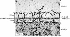
- FIG. 2 is a reflection micrograph of a diffusion pair sample obtained in Example 1.
- 2 is a microscopic Raman spectrum of a diffusion pair sample obtained in Example 1.
- FIG. (A) is a Raman spectrum from La 2 SiO 5
- (b) is a Raman spectrum from apatite-type lanthanum silicate
- (c) is a Raman spectrum from La 2 Si 2 O 7 .
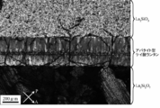
- FIG. 3 is a polarization micrograph of the diffusion pair sample obtained in Example 1, in which almost all columnar crystals of apatite-type lanthanum silicate are in a diagonal position.
- Arrow P represents the vibration direction of the polarizer
- arrow A represents the vibration direction of the analyzer.
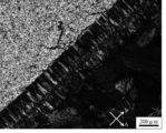
- 2 is a polarization micrograph of a diffusion pair sample obtained in Example 1, and almost all columnar crystals of apatite-type lanthanum silicate are in the extinction position.
- Arrow P represents the vibration direction of the polarizer
- arrow A represents the vibration direction of the analyzer.
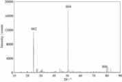
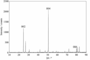
- 2 is an X-ray powder diffraction pattern of the crystallographically-oriented ceramic obtained in Example 1.
- FIG. 3 is an X-ray powder diffraction pattern of the crystallographically-oriented ceramic obtained in Example 2.
- 4 is an X-ray powder diffraction pattern of the crystallographically-oriented ceramic obtained in Example 3.
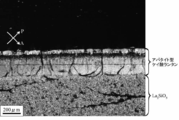
- 4 is a reflection micrograph of a diffusion pair sample obtained in Example 3.
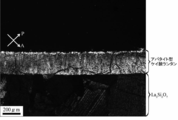
- FIG. 4 is a reflection micrograph of a diffusion pair sample obtained in Example 4. It is a polarization microscope photograph of the diagonal position of the diffusion pair sample obtained in Example 4, and almost all columnar crystals of the apatite type lanthanum silicate are in the diagonal position. Arrow P indicates the vibration direction of the polarizer, and arrow A indicates the vibration direction of the analyzer. FIG. 6 is a polarization micrograph of the extinction level of the diffusion pair sample obtained in Example 4, and almost all of the columnar crystals of apatite type lanthanum silicate are in the extinction position. Arrow P indicates the vibration direction of the polarizer, and arrow A indicates the vibration direction of the analyzer. 6 is a reflection micrograph of a diffusion pair sample obtained in Example 5.
- FIG. 6 is a polarization micrograph of the extinction level of the diffusion pair sample obtained in Example 5, and almost all of the columnar crystals of apatite type lanthanum silicate are in the extinction position.
- Arrow P indicates the vibration direction of the polarizer
- arrow A indicates the vibration direction of the analyzer.
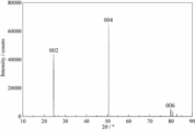
- FIG. 7 is an X-ray powder diffraction pattern of the crystallographically-oriented ceramic obtained in Example 5.
- Example 7 is an X-ray powder diffraction pattern of the crystallographically-oriented ceramic obtained in Example 6. It is a chart which shows the EPMA measurement result of the crystal orientation ceramics to which this invention is applied. It is the figure which added the regression line to the chart which shows the EPMA measurement result of FIG.
- the present invention is a crystal-oriented ceramic, in which a compound is formed in the vicinity of a bonding interface in which a plurality of substances having different average chemical compositions are in contact with each other, and the crystal of the compound is oriented vertically to the original bonding interface. It is characterized by. Further, the present invention is a method for producing a crystallographically-oriented ceramic by bringing a plurality of substances having different average chemical compositions into contact with each other and having a bonding interface and heating the material at a predetermined temperature. The temperature is a temperature at which element diffusion occurs between the plurality of substances and a new compound is formed, and crystals of the generated compound are vertically oriented with respect to the original bonding interface. .
- “ceramics” in the present invention refers to a substance having a crystal structure by heating.
- diffusion is performed using two substances whose average chemical compositions are different from each other (however, the shape and state of this substance are arbitrary and are not particularly specified such as a green compact or a sintered body).
- the shape and state of this substance are arbitrary and are not particularly specified such as a green compact or a sintered body.
- a new compound is formed in the vicinity of the bonding interface, so that the specific crystal axis of this compound is in a direction perpendicular to the original bonding interface.
- a crystallographically-oriented ceramic is provided that is oriented in one direction along.
- the diffusion pair is heated at a predetermined temperature to produce crystal oriented ceramics.
- the predetermined temperature is preferably 1300 ° C. or higher, and more preferably 1400 ° C. or higher.
- the heating time may be short at high temperatures, whereas the heating time needs to be long at low temperatures. It is preferable to set the heating temperature in consideration of the relationship.
- La 2 SiO 5 and La 2 Si 2 O 7 are used as two substances having different average chemical compositions, and a layer of crystallographically oriented ceramics is produced by changing the heating temperature and heating time. Show. As shown in Table 1, based on the correlation between the heating temperature and the heating time and the thickness of the crystal oriented ceramic layer to be produced, the crystal oriented ceramic having a desired thickness can be obtained by appropriately setting the heating temperature and the heating time. Can be generated. In Table 1, “La 2 SiO 5 side” and “La 2 Si 2 O 7 side” mean the thickness of the produced crystal-oriented ceramic layer on the La 2 SiO 5 side and La 2 Si 2 O 7, respectively.
- the “thickness” is the sum of “La 2 SiO 5 side” and “La 2 Si 2 O 7 side”, and is a one-dimensional oriented crystal layer (crystal oriented ceramic layer) of an apatite structure Indicates the thickness. Also, in Table 1, the sum of the thickness of “La 2 SiO 5 side” and the thickness of “La 2 Si 2 O 7 side” and the thickness of the layer of crystallographically oriented ceramics are completely rounded off to the nearest whole number. Does not match.
- the heating temperature is preferably 1400 to 1600 ° C., preferably 1500 ° C. to 1600 ° C., and the heating time is preferably 5 hours to 100 hours, and preferably 25 hours to 50 hours.
- the heating atmosphere is air or an oxygen atmosphere. The reason why such conditions are desirable is that the desired apatite structure layer (crystal-oriented ceramic layer) is formed and that the amount of oxygen in the crystal is insufficient and the ionic conductivity is not lowered.
- the new compound generated near the bonding interface may be generated not only on both sides of the bonding interface but also on one side.
- a substance having a chemical composition different from the chemical composition of the substrate is dispersed in close contact with the surface of the substrate having a certain chemical composition by a method such as spray coating or dip coating, and heated at a high temperature.
- a method such as spray coating or dip coating, and heated at a high temperature.
- highly oriented ceramics may be generated on the substrate surface.
- This method is similar to the diffusion pair method described above in that a new compound is generated in the vicinity of the bonding interface between two substances having different average chemical compositions.
- diffusion is performed using a substance composed of a single or plural phases whose average chemical composition is represented by A and a substance composed of a single or plural phases whose average chemical composition is represented by B.
- A a substance composed of a single or plural phases whose average chemical composition is represented by A
- B a substance composed of a single or plural phases whose average chemical composition is represented by B.
- element diffusion occurs in the vicinity of the bonding interface, and the general formula is A x B 1-x (where x is a number in the range of 0 ⁇ x ⁇ 1).
- the specific crystal axis of the compound A x B 1-x is oriented in one direction along the direction perpendicular to the original bonding interface. It is to provide crystal-oriented ceramics.
- Non-Patent Document 2 and Non-Patent Document 3 the general formula of lanthanum silicate having an apatite crystal structure is La 9.33 + 2x (SiO 4 ) 6 O 2 + 3x (where x is ⁇ 0.10 ⁇ x ⁇ It is a number in the range of 0.33.) Therefore, lanthanum silicate having an apatite type crystal structure is produced by reacting La 2 SiO 5 and La 2 Si 2 O 7 at a high temperature, reacting La 2 SiO 5 and SiO 2 at a high temperature, or Since La 2 Si 2 O 7 and La 2 O 3 are produced by a reaction at a high temperature, these three kinds of combinations were selected as a combination of diffusion pairs in Examples described later. In the present invention, a compound containing a rare earth element other than lanthanum can also be used.
- the crystal-oriented ceramic of the present invention is composed of a compound formed in the vicinity of a bonding interface in which a plurality of substances having different average chemical compositions are in contact with each other, and is vertically aligned with respect to the original bonding interface. It is characterized by having a crystal structure. That is, as described above, the crystal oriented ceramic is a crystal oriented ceramic in which a specific crystal axis is oriented in one direction along a direction perpendicular to the original bonding interface. In addition, the degree of orientation of the crystal-oriented ceramic of the present invention is 49% or higher, which is higher than that of the conventional one.
- the reason why the degree of orientation is desirably 49% or more is that the oxygen ion conductivity of the entire structure is improved when the degree of orientation with respect to the c-axis, which is the moving direction of oxygen ions, is increased.
- the compound can be a lanthanum silicate having an apatite-type crystal structure, and in this case, has a crystal structure in which the c-axis is oriented along the vertical direction with respect to the original bonding interface.
- the crystal-oriented ceramic of the present invention includes (1) a first layer mainly composed of La 2 SiO 5 and a main component composed of La 2 Si 2 O 7 as a plurality of substances having different average chemical compositions.
- An embodiment including a first layer mainly containing 3 and a second layer mainly containing La 2 Si 2 O 7 is preferable.
- the compound generated at the bonding interface between the first layer and the second layer is a compound having a crystal structure in which the c-axis is vertically aligned with respect to the bonding interface, that is, the crystal orientation of the present invention. Ceramics.
- the crystallographic ceramics of the present invention have crystal axes oriented in one direction, the ion conductivity in the direction along the direction is high, and are useful as an ion conductor.
- the ionic conductivity of lanthanum silicate (La 9.33 + 2x (SiO 4 ) 6 O 2 + 3x (0.02 ⁇ x ⁇ 0.13)) having an apatite-type crystal structure as the crystal-oriented ceramic of the present invention is shown.
- the measured value was 5.0 ⁇ 10 ⁇ 3 (S / cm) at 400 ° C.
- the ionic conductivity of La 9.33 (SiO 4 ) 6 O 2 outside the scope of the present invention was a literature value.
- the ionic conductivity (5.0 ⁇ 10 ⁇ 3 (S / cm)) at 400 ° C. of the crystal-oriented ceramic of the present invention is the ionic conductivity at 500 ° C. (about 2.31 ⁇ 10 ⁇ 4 (S
- the crystal-oriented ceramic of the present invention is 400 ° C. lower than the reference value of 500 ° C., but the ionic conductivity is one order of magnitude higher than the reference value. A large value was shown.
- the ionic conductivity of the crystal-oriented ceramic of the present invention was obtained as follows. First, after a sample was formed into a 3 mm ⁇ 3 mm test piece (thickness 0.4 mm), a platinum thin film (thickness: 0.4 ⁇ m) was formed on the front and back surfaces of the test piece by sputtering. Next, using the formed platinum thin film as an electrode, the bulk resistance between the electrodes was measured by the AC impedance method, and the ionic conductivity was calculated from the bulk resistance and the size of the test piece. The platinum thin film can also be formed by baking a platinum paste.
- Measurement conditions and equipment used are as follows. [Measurement conditions and equipment used] ⁇ Measurement frequency: 0.1 to 1 MHz ⁇ Measurement temperature: Room temperature to 400 °C -Furnace atmosphere: Atmosphere-PC software: Toyo Technica Co., Ltd., ZPlot ⁇ Frequency response analyzer: Toyo Technica Co., Ltd., 1260 type ⁇ Desktop lamp heating furnace: ULVAC Riko Co., Ltd., MILA-3000
- the EPMA analysis result of the lanthanum silicate which is the crystal-oriented ceramic of the present invention is shown. Specifically, a diffusion composed of a first layer mainly composed of La 2 SiO 5 as a plurality of substances having different average chemical compositions and a second layer mainly composed of La 2 Si 2 O 7
- the results of EPMA analysis of the laminate after forming a pair and heating the diffusion pair at a high temperature to form lanthanum silicate in the vicinity of the bonding interface are shown.
- FIG. 20 is a chart showing the results of the EPMA analysis.
- the horizontal axis indicates the distance ( ⁇ m) from the end face of La 2 SiO 5
- the vertical axis indicates the value of the ratio of La to Si (La / Si).
- FIG. 20 shows the La / Si ratio at a predetermined distance from the end face of La 2 SiO 5 , the points distributed on the left are La 2 SiO 5 analysis points, and the points distributed on the right are La 2 Si 2.
- the analysis points of O 7 and the points distributed in the middle are the analysis points of lanthanum silicate produced.
- FIG. 20 shows that lanthanum silicate has a high La / Si ratio on the La 2 SiO 5 side and gradually decreases toward the La 2 Si 2 O 7 side.
- FIG. 21 shows a regression line added to the points distributed in FIG. As shown in FIG.
- the lanthanum silicate which is the crystal-oriented ceramic of the present invention, is presumed to exhibit high ionic conductivity because the La / Si ratio is larger than 1.555. It is clear that the ionic conductivity is high.
- the method for producing a crystal-oriented ceramic according to the present invention includes a step of bringing a plurality of substances having different average chemical compositions into contact with each other to have a bonding interface, and the plurality of substances having the above-described configuration. Heating at a temperature at which element diffusion occurs between the plurality of substances to produce crystal oriented ceramics in the vicinity of the joint interface, wherein the crystal oriented ceramics are vertically oriented with respect to the original joint interface It is characterized by comprising a compound having a crystal structure.
- a crystal-oriented ceramic having a high degree of orientation can be obtained without complicating the manufacturing process as in the prior art.
- the compound can be a lanthanum silicate having an apatite-type crystal structure, and in this case, has a crystal structure in which the c-axis is oriented along the vertical direction with respect to the original bonding interface.
- the plurality of substances having different average chemical compositions are the same as those of the crystal-oriented ceramic of the present invention described above, and preferred examples are also the same.
- a substance other than the crystal-oriented ceramic generated near the bonding interface of the plurality of substances or a substance other than lanthanum silicate having an apatite-type crystal structure is unnecessary. It is preferable to provide a step of removing the substance.
- the removing means is not particularly limited, and examples thereof include mechanical means such as polishing and grinding, chemical means such as etching, and peeling due to a difference in thermal expansion coefficient.
- the crystal-oriented ceramic of the present invention is preferably made into a plate-like body by removing a reaction raw material such as La 2 SiO 5 . That is, a plate-like body made of lanthanum silicate having an apatite-type crystal structure, wherein the lanthanum silicate has a crystal structure in which the c-axis of the lanthanum silicate is oriented in a direction substantially perpendicular to the main surface of the plate-like body. Is a plate-like body.
- the reason why the crystal-oriented ceramic is a plate-like body is that it is a suitable shape when used as a solid electrolyte such as an oxygen sensor.
- the main surface of the plate-like body may be either a flat surface or a curved surface, but it is desirable that the normal direction of the main surface coincides with the orientation direction of the c-axis.
- the plate-like body includes a substance A composed of at least one selected from La 2 SiO 5 and La 2 O 3 and a substance B composed of at least one selected from La 2 Si 2 O 7 and SiO 2.
- a substance A composed of at least one selected from La 2 SiO 5 and La 2 O 3
- a substance B composed of at least one selected from La 2 Si 2 O 7 and SiO 2.
- the removing method is not particularly limited, and examples thereof include mechanical means such as polishing and grinding, chemical means such as etching, and peeling due to a difference in thermal expansion coefficient.
- the crystal orientation degree of the lanthanum silicate having the apatite type crystal structure is preferably 49% or more. This is because the oxygen ion conductivity of the entire structure is improved when the degree of orientation with respect to the c-axis, which is the moving direction of oxygen ions, is increased.
- a diffusion pair is prepared using raw powders of La 2 SiO 5 and La 2 Si 2 O 7 , SiO 2 , and La 2 O 3 , and these are heated at a high temperature so that the c-axis is
- a method for producing a lanthanum silicate polycrystal having an apatite-type crystal structure oriented in one direction will be described.
- La 2 SiO 5 and La 2 Si 2 O 7 , SiO 2 , La 2 Needless to say, the present invention can be realized even when a highly oriented ceramic having a chemical composition and crystal structure different from that of lanthanum silicate is manufactured using a diffusion pair having a chemical composition different from that of O 3 .
- a diffusion pair is prepared using two green compacts having different chemical compositions, and heated at a high temperature to generate highly oriented ceramics near the bonding interface.
- a substance having a chemical composition different from the chemical composition of the substrate is dispersed and closely adhered to the surface of the substrate having a certain chemical composition by a method such as spray coating or dip coating.
- the present invention is realized even when highly oriented ceramics are produced on the substrate surface by heating at a high temperature.
- Example 1 In this example, it has an apatite type crystal structure obtained by diffusion pair using a green compact whose chemical formula is represented by La 2 SiO 5 and a green compact whose chemical formula is represented by La 2 Si 2 O 7. A method for producing c-axis oriented ceramics of lanthanum silicate will be described.
- a lanthanum oxide (La 2 O 3 ) reagent and a silicon oxide (SiO 2 ) reagent were weighed in such a ratio that a composition having a chemical composition represented by La 2 SiO 5 was produced to prepare a raw material mixed powder.
- This raw material mixed powder was uniaxially pressed into a pellet having a diameter of about 12 mm and a height of about 3 mm, heated in an electric furnace at 1200 ° C. for 1 hour, then taken out of the electric furnace and cooled.
- the obtained sample is pulverized and mixed, and this powder sample is uniaxially pressed into a pellet with a diameter of about 12 mm and a height of about 3 mm, heated in an electric furnace at 1600 ° C. for 3 hours, and then removed from the electric furnace. And cooled.
- the obtained sample was pulverized to obtain a powdery La 2 SiO 5 sample.
- lanthanum oxide (La 2 O 3 ) and silicon oxide (SiO 2 ) were weighed as starting materials at a rate that a composition represented by a chemical composition represented by La 2 Si 2 O 7 was produced to prepare a raw material mixed powder.
- This raw material mixed powder was uniaxially pressed into a pellet having a diameter of about 12 mm and a height of about 3 mm, heated in an electric furnace at 1200 ° C. for 1 hour, then taken out of the electric furnace and cooled.
- the obtained sample is pulverized and mixed, and this powder sample is uniaxially pressed into a pellet with a diameter of about 12 mm and a height of about 3 mm, heated in an electric furnace at 1600 ° C. for 3 hours, and then removed from the electric furnace. And cooled.
- the obtained sample was pulverized to obtain a powdery La 2 Si 2 O 7 sample.
- a powdery La 2 SiO 5 sample (about 0.63 g) was uniaxially pressed to produce a pellet-shaped green compact having a diameter of about 12 mm and a height of about 2 mm. Further, a powdery La 2 Si 2 O 7 sample (about 0.54 g) was uniaxially pressed to produce a pellet-shaped green compact having a diameter of about 12 mm and a height of about 2 mm.
- a plurality of diffusion pairs in which these two green compacts were superimposed were prepared, heated in an electric furnace at 1600 ° C for 25 hours, and then cooled to room temperature with the furnace turned off for about 3 hours. .
- the polishing surface of the polishing piece was attached to a slide glass using an epoxy resin, and an excess portion was cut off using a diamond cutter, and then polished with emery paper and diamond paste to produce a thin piece.
- a columnar crystal with a height of about 230 ⁇ m and a width of about 45 ⁇ m was found at the interface on the La 2 SiO 5 side of the original bonding interface. It is observed that the crystals grow and gather vertically, and a columnar crystal with a size of about 150 ⁇ m in height and about 45 ⁇ m in width is formed at the interface on the La 2 Si 2 O 7 side of the original junction interface.
- One of the heat treated diffusion pair samples was cut with a diamond cutter in a direction parallel to the original bonding interface so that the apatite-type lanthanum silicate polycrystal was exposed, and the cross section was mirror-polished using a diamond pace. Thus, a polished piece was produced.
- a high-resolution X-ray powder diffractometer using CuK ⁇ 1 line (45kV ⁇ 40mA) as incident light was used. The profile intensity of the diffracted X-rays in the 2 ⁇ range from ° to 90.0 ° was measured (FIG. 5).
- the apatite-type lanthanum silicate polycrystal has a c-axis along the direction perpendicular to the original bonding interface. Were confirmed to be oriented.
- the degree of orientation of this polycrystal can be calculated from the Lotgering equation shown in Equation (1).
- ⁇ 0 is the sum of the intensities of all diffracted reflections that appear between 10.0 ° and 90.0 ° in the 2 ⁇ range of diffracted X-rays in the unoriented apatite-type lanthanum silicate, and the diffraction plane index Is obtained by equation (2) using the sum of the diffraction reflection intensities of 002 and 004, 006.
- ⁇ I 0 (hkl) in equation (2) represents the total intensity of total diffraction reflections that appeared in the 2 ⁇ range between 10.0 ° and 90.0 °
- ⁇ I 0 (00l) in equation (2) is the diffraction plane index. Represents the sum of the diffraction reflection intensities of 002 and 004, 006.
- ⁇ in the formula (1) is the sum of the total diffraction reflection intensities appearing when the 2 ⁇ range of diffracted X-rays is between 10.0 ° and 90.0 ° in the oriented apatite-type lanthanum silicate, and the diffraction plane index is Using the sum of the diffraction reflection intensities of 002, 004, and 006, it is obtained by equation (3).
- ⁇ I (hkl) in equation (3) represents the total intensity of all diffraction reflections that appeared in the 2 ⁇ range between 10.0 ° and 90.0 °
- ⁇ (00l) in equation (3) has a diffractive surface index of 002.
- Example 2 In the present example, similar to Example 1, it is obtained by a diffusion pair using a green compact whose chemical formula is represented by La 2 SiO 5 and a green compact whose chemical formula is represented by La 2 Si 2 O 7. A method for producing a highly oriented ceramic of apatite type lanthanum silicate will be described. In this example, the thickness of the La 2 SiO 5 compact forming the diffusion pair is thinner than that used in Example 1, and the La 2 SiO 5 layer is completely formed after the diffusion pair is heat-treated. The apatite-type lanthanum silicate is exposed on the surface.
- a powdery La 2 SiO 5 sample and a powdery La 2 Si 2 O 7 sample were synthesized in the same manner as described in Example 1, respectively.
- a powdery La 2 Si 2 O 7 sample (about 0.54 g) was uniaxially pressed to produce a pellet-shaped green compact having a diameter of about 12 mm and a height of about 2 mm.
- a powdery La 2 SiO 5 sample (about 0.16 g) was uniaxially pressed to produce a pellet-shaped green compact having a diameter of about 12 mm and a height of about 0.5 mm.
- a plurality of diffusion pairs in which these two green compacts were superimposed were produced, heated in an electric furnace at 1600 ° C for 100 hours, and then cooled to room temperature with the furnace turned off for about 3 hours. .
- the diffraction X of this polycrystal was analyzed in the same manner as described in Example 1.
- the line profile intensity was measured (FIG. 6).
- the apatite-type lanthanum silicate polycrystal exposed on the surface of the diffusion pair was perpendicular to the surface. It was confirmed that the c-axis was oriented along the direction.
- the degree of orientation of this polycrystal is 93% when calculated from the Lotgering equation in the same manner as in Example 1, which is an extremely high degree of orientation.
- Example 3 lanthanum silicate having an apatite type crystal structure obtained by a diffusion pair using a green compact having a chemical formula represented by La 2 SiO 5 and a green compact having a chemical formula represented by SiO 2 .
- a method for producing c-axis oriented ceramic will be described.
- a powdery La 2 SiO 5 sample was synthesized by the same method as described in Example 1. This powder sample (about 0.63 g) was uniaxially pressed to produce a pellet-shaped green compact having a diameter of about 12 mm and a height of about 2 mm. Further, a powdered silicon oxide (SiO 2 ) reagent (about 0.27 g) was uniaxially pressed to prepare a pellet-shaped green compact having a diameter of about 12 mm and a height of about 2 mm. A plurality of diffusion pairs were produced by superimposing these two green compacts, and these were heated in an electric furnace at 1600 ° C for 25 hours, and then the furnace was turned off and cooled to room temperature over about 3 hours. .
- the intensity of the diffracted X-ray profile in the 2 ⁇ range from 10.0 ° to 90.0 ° was determined in the same manner as described in Example 1. Was measured (FIG. 7).
- the X-ray powder diffraction pattern reflections with diffraction surface indices of 002, 004, and 006 are remarkably observed, so this apatite-type lanthanum silicate polycrystal is exposed by peeling off the unreacted SiO 2 portion. It was confirmed that the c-axis was oriented along the direction perpendicular to. The degree of orientation of this polycrystal is 53% when calculated from the Lotgering equation, which is an extremely high degree of orientation.
- One of the heat treated diffusion pair samples was processed into a polished piece having a polished surface perpendicular to the original bonded interface in the same manner as described in Example 1.
- a strip-shaped reaction product having a thickness of about 290 ⁇ m was observed on both sides of the original bonding interface (FIG. 8). This reaction product is formed on both sides of the original bonding interface, the thickness of the strip-like product on the La 2 SiO 5 side is about 240 ⁇ m, and the strip-like product on the side where SiO 2 was present Is about 50 ⁇ m thick.
- this reaction product was identified using micro-Raman spectroscopy, it was a lanthanum silicate having an apatite-type crystal structure on both sides of the bonding interface, so (14 + 3x) La 2 SiO 5 + (4-3x) SiO 2 ⁇ 3La 9.33 + 2x (SiO 4 ) 6 O 2 + 3x (where x is a number in the range of ⁇ 0.10 ⁇ x ⁇ 0.33) occurs near the original junction interface, and La 2 SiO 5 It is considered that apatite-type lanthanum silicate was formed from SiO 2 and SiO 2 .
- the polished piece was processed into a thin piece by the same method as described in Example 1.
- a microstructure was observed with an orthogonal polar using a polarizing microscope (FIG. 9)
- a columnar crystal having a size of about 240 ⁇ m in height and about 45 ⁇ m in width was found at the interface on the La 2 SiO 5 side of the original bonding interface. It is observed that the crystal grows vertically and aggregates, and on the SiO 2 side of the original bonding interface, a columnar crystal with a size of about 50 ⁇ m height ⁇ about 45 ⁇ m width grows perpendicularly to the interface The state of gathering was observed.
- an orthogonal polar FIG.
- Example 4 it has an apatite type crystal structure obtained by diffusion pair using a green compact whose chemical formula is represented by La 2 Si 2 O 7 and a green compact whose chemical formula is represented by La 2 O 3.
- a method for producing c-axis oriented ceramics of lanthanum silicate will be described.
- a powdery La 2 Si 2 O 7 sample was synthesized by the same method as described in Example 1. This powder sample (about 0.54 g) was uniaxially pressed to produce a pelletized green compact having a diameter of about 12 mm and a height of about 2 mm. Further, a powdery lanthanum oxide (La 2 O 3 ) reagent (about 0.75 g) was uniaxially pressed to produce a pellet-shaped green compact having a diameter of about 12 mm and a height of about 2 mm. A plurality of diffusion pairs in which these two green compacts were superimposed were prepared, heated in an electric furnace at 1600 ° C for 25 hours, and then cooled to room temperature with the furnace turned off for about 3 hours. .
- Example 2 A sample similar to the diffusion pair described in Example 1 was obtained, but the unreacted La 2 O 3 portion reacted with moisture in the air and peeled off. When the surface exposed by peeling off the unreacted La 2 O 3 portion was examined by micro-Raman spectroscopy, it was confirmed that the surface was covered with fine apatite-type lanthanum silicate crystals.
- the intensity of the diffracted X-ray profile in the 2 ⁇ range from 10.0 ° to 90.0 ° was determined in the same manner as described in Example 1. Was measured (FIG. 11).
- the X-ray powder diffraction pattern reflections with diffraction plane indices of 002, 004, and 006 are remarkably observed, so this apatite-type lanthanum silicate polycrystal is exposed by peeling off the unreacted La 2 O 3 portion. It was confirmed that the c-axis was oriented along a direction perpendicular to the surface. The degree of orientation of this polycrystal is 49% when calculated from the Lotgering equation, which is an extremely high degree of orientation.
- One of the above heat-treated diffusion pair samples is a polishing piece having a polishing surface perpendicular to the surface exposed by peeling off the unreacted La 2 O 3 portion in the same manner as described in Example 1. It was processed into. When the polished surface was observed with a reflection microscope, a strip-like reaction product having a thickness of about 230 ⁇ m was observed (FIG. 12). Since the original bonding interface could not be confirmed, it is considered that the region including the original bonding interface was peeled off when the unreacted La 2 O 3 portion was peeled off.
- Example 5 In the present example, similar to Example 1, it is obtained by a diffusion pair using a green compact whose chemical formula is represented by La 2 SiO 5 and a green compact whose chemical formula is represented by La 2 Si 2 O 7. A method for producing a highly oriented ceramic of apatite type lanthanum silicate will be described.
- a single layer of La 2 SiO 5 compact (0.80 mm thickness) was sandwiched between two layers of La 2 Si 2 O 7 compact and a diffusion layer consisting of three layers was used. After this diffusion pair is heat-treated, the intermediate La 2 SiO 5 layer disappears completely, and apatite-type lanthanum silicate is generated between the La 2 Si 2 O 7 sintered body layers.
- a powdery La 2 SiO 5 sample and a powdery La 2 Si 2 O 7 sample were synthesized in the same manner as described in Example 1, respectively.
- a powdery La 2 Si 2 O 7 sample (about 0.90 g) was uniaxially pressed to produce two pellets of green compact with a diameter of about 20 mm and a height of about 1 mm.
- a powdered La 2 SiO 5 sample (about 1.30 g) was uniaxially pressed to produce a pellet-shaped green compact having a diameter of about 20 mm and a height of about 0.80 mm.
- a plurality of diffusion pairs were produced by laminating these three green compacts in the order of La 2 Si 2 O 7 / La 2 SiO 5 / La 2 Si 2 O 7 , and these were formed in an electric furnace at 1600 ° C. for 200 After heating for an hour, the furnace was turned off and cooled to room temperature over about 3 hours.
- the polishing surface of the polishing piece was attached to a slide glass using an epoxy resin, and an excess portion was cut off using a diamond cutter, and then polished with emery paper and diamond paste to produce a thin piece.
- a microstructure was observed with an orthogonal polar using a polarizing microscope (FIG. 16)
- an apatite-type lanthanum silicate having a height of about 400 ⁇ m and a width of about 45 ⁇ m was formed on the La 2 SiO 5 side of the original bonding interface. It is observed that the columnar crystals grow and gather perpendicular to the interface, and the La 2 Si 2 O 7 side of the original junction interface has a height of about 350 ⁇ m ⁇ width of about 45 ⁇ m. It was observed that the columnar crystals grew and assembled perpendicularly to the interface. These apatite-type lanthanum silicate columnar crystals reached a total thickness of about 1500 ⁇ m.
- One of the heat-treated diffusion pair samples was cut out with a diamond cutter in a direction parallel to the original bonding interface so that the apatite-type lanthanum silicate polycrystal was exposed, and the cross section was mirror-polished using diamond paste. Thus, a polished piece was produced.
- a high-resolution X-ray powder diffractometer using CuK ⁇ 1 line (45kV ⁇ 40mA) as incident light was used. The profile intensity of the diffracted X-rays in the 2 ⁇ range from ° to 90.0 ° was measured (FIG. 18).
- the apatite-type lanthanum silicate polycrystal has a c-axis along the direction perpendicular to the original bonding interface. Were confirmed to be oriented. The degree of orientation of this polycrystal is 91% when calculated from the Lotgering equation, which is an extremely high degree of orientation.
- Example 6 In this example, the c-axis of lanthanum silicate having an apatite type crystal structure obtained by a diffusion pair using a sintered body having a chemical formula represented by La 2 SiO 5 and a thin film having a chemical formula represented by SiO 2 A method for manufacturing oriented ceramics will be described.
- a powdery La 2 SiO 5 sample was synthesized by the same method as described in Example 1. This powder sample (about 2.50 g) is uniaxially pressed to produce a number of pellet-shaped green compacts with a diameter of about 20 mm and a height of about 2 mm, and these are heated in an electric furnace at 1600 ° C for 2 hours. Thereafter, it was taken out from the electric furnace and cooled.
- the obtained gel was applied to a La 2 SiO 5 sintered body by a dip coating method. This was heated in an electric furnace to 500 ° C. at a heating rate of 50 ° C. per hour, held for 1 hour, cooled at a cooling rate of 50 ° C. per hour to form a La 2 SiO 5 sintered body with silicon oxide A (SiO 2 ) thin film was formed. These were heated in an electric furnace at 1600 ° C. for 25 hours, and then the furnace was turned off and cooled to room temperature over about 3 hours.
- the diffraction X of this polycrystal was analyzed in the same manner as described in Example 1.
- the line profile intensity was measured (FIG. 19).
- reflections with diffraction plane indices of 002, 004, and 006 were remarkably observed. Therefore, the apatite-type lanthanum silicate polycrystal exposed on the surface of the diffusion pair was perpendicular to the surface. It was confirmed that the c-axis was oriented along the direction. The degree of orientation of this polycrystal is 28% when calculated from the Lotgering equation, which is a high degree of orientation.
Landscapes
- Chemical & Material Sciences (AREA)
- Organic Chemistry (AREA)
- Engineering & Computer Science (AREA)
- Ceramic Engineering (AREA)
- Materials Engineering (AREA)
- Structural Engineering (AREA)
- Inorganic Chemistry (AREA)
- Manufacturing & Machinery (AREA)
- Compositions Of Oxide Ceramics (AREA)
- Ceramic Products (AREA)
Abstract
結晶軸が一方向に配向している結晶配向セラミックス、及び該結晶配向セラミックスを複雑なプロセスを経ることなく製造し得る製造方法を提供する。 La2SiO5を主成分とする第1の層とLa2Si2O7を主成分とする第2の層とを接触させて接合界面を有する構成とし、これを所定温度で加熱することによって、接合界面の近傍に、アパタイト型の結晶構造を有するランタンケイ酸塩が生成し、その結晶が元の接合界面に対してc軸が垂直方向に沿って配向している結晶配向セラミックスを製造する製造方法、及び該製造方法によって得られる結晶配向セラミックスである。
Description
本発明は、結晶配向セラミックス及びその製造方法に関し、詳しくは特定の結晶軸が一方向に配向している結晶配向セラミックス及びその製造方法に関し、このような結晶配向セラミックスを用いて、例えばイオン伝導素子、誘電素子、マイクロ波誘電素子、熱電素子、焦電素子、磁気抵抗素子、磁性素子、圧電素子、電解駆動変位素子、抵抗素子、電子伝導素子、サーミスタ素子を構成することができる。
一般式がLn9.33+2x(SiO4)6O2+3x(但し、Lnは希土類元素から選択された1種類以上の元素であり、xは-0.10≦x≦0.33の範囲の数である。)で表される、アパタイト型の結晶構造を有する希土類ケイ酸塩は、特許文献1および特許文献2において500℃から700℃程度の中温度領域であっても比較的優れた酸化物イオン伝導性を示すことが報告されている。このようなアパタイト型化合物からなる酸化物イオン伝導体を固体電解質型燃料電池の電解質とした場合、YSZ(イットリア安定化ジルコニア)やSDC(スカンジナドープドセリア)、LSGM(ランタンガレート系酸化物)を電解質とする燃料電池に比べて運転温度を低温にすることができ、加熱に要するエネルギー等を省力化することができるという利点がある。このようなアパタイト型の結晶構造を有する希土類ケイ酸塩からなる酸化物イオン伝導体は、従来、Ln2O3およびSiO2などの酸化物を出発原料に用いて、原料粉末を混合して成形・焼成する方法や、同じくLn2O3およびSiO2などの酸化物を出発原料に用いて、固相反応法によりアパタイト型希土類ケイ酸塩からなる粉末を合成し、次に合成された粉末を成形・焼結する方法により製造するのが一般的であった。
一方、アパタイト型化合物が有する酸化物イオン伝導特性は、特許文献3および非特許文献1において、ベルヌーイ法やチョコラルスキー法等にて作製された単結晶から、c軸に沿う平行方向に延在する箇所と、c軸に対して直交方向に延在する箇所から切り出した試料の酸化物イオン伝導率を比較すると、c軸に沿う平行方向に延在する箇所から切り出した試料の方が優れているという報告があり、酸化物イオン伝導率はc軸方向に沿う平行方向が高い。
特許文献3には、アパタイト型化合物の結晶粉末を溶媒に添加してスラリーとした後、このスラリーを磁場の存在下に配置することにより、スラリー中の結晶が概ね配向する。これにより結晶が概ね特定方向に配向した成形体が得られる。このような成形体を焼成することで、アパタイト型化合物(La10Si6027)からなり、かつロットゲーリング法による配向度が42%である、酸化物イオン伝導率に異方性を示す結晶配向セラミックスを得ることができる。
この特許文献3に開示された結晶配向セラミックスの製造方法では、適切な粘性のスラリーを準備する必要があり、さらにこのスラリーを容器ごと磁場中に静置する必要があるため、製造プロセスが複雑になるという問題があった。
また、特許文献4には、チタン酸ビスマス(Bi4Ti3012)からなる板状テンプレート粒子からなる粉末にBi2O3とNa2CO3、TiO2を所定の比率で混合し、この混合物を板状粉末が配向するように成形して焼結することにより、チタン酸ビスマス(Bi0.5Na0.5Ti03)からなり、かつロットゲーリング法による配向度が34%である結晶配向セラミックスを得ることができる。
この特許文献4に開示された方法の場合、高配向度を有する結晶配向セラミックスを得るためには、多量の板状テンプレート粒子を用いる必要がある。しかしながら、この方法では良好な形状のテンプレート粒子を多量に合成する必要があり、製造プロセスが複雑になるという問題があった。
M. Higuchi, Y. Masubuchi, S. Nakayama, S. Kikkawa, K. Kodaira, K., Solid State Ionics 174, 73-80 (2004).
T. Iwata, E. Bechade, K. Fukuda, O. Masson, I. Julien, E. Champion, P. Thomas, J. Am. Ceram. Soc. 91, 3714-3720 (2008).
R. Ali, M. Yashima, Y. Matsushita, H. Yoshioka, F. Izumi, J.Solid State Chem. 182, 2846-2851 (2009).
本発明は、結晶軸が一方向に配向している結晶配向セラミックスを提供すること、およびそのような結晶配向セラミックスを、複雑なプロセスを経ることなく、製造することができる結晶配向セラミックスの製造方法を提供することを目的とする。
上記課題を解決する本発明は以下の通りである。
(1)結晶配向セラミックスであって、平均の化学組成が互いに異なる複数の物質を接触させた接合界面の近傍に化合物が生成され、その化合物の結晶が元の接合界面に対して垂直配向していることを特徴とする結晶配向セラミックス。
(1)結晶配向セラミックスであって、平均の化学組成が互いに異なる複数の物質を接触させた接合界面の近傍に化合物が生成され、その化合物の結晶が元の接合界面に対して垂直配向していることを特徴とする結晶配向セラミックス。
(2)平均の化学組成が互いに異なる複数の物質を接触させて接合界面を有する構成とし、これを所定温度で加熱することによって、結晶配向セラミックスを製造する方法であって、前記所定温度が前記複数の物質の間で元素拡散が生じ、新たな化合物が生成する温度であり、前記生成された化合物の結晶が、元の接合界面に対して垂直配向していることを特徴とする結晶配向セラミックスの製造方法。
(3)La2SiO5を主成分とする第1の層とLa2Si2O7を主成分とする第2の層を接触させた接合界面の近傍にアパタイト型の結晶構造を有するランタンケイ酸塩が生成され、そのランタンケイ酸塩の結晶が、元の接合界面に対してc軸が垂直方向に沿って配向していることを特徴とする結晶配向セラミックス。
(4)La2SiO5を主成分とする第1の層とLa2Si2O7を主成分とする第2の層を接触させて接合界面を有する構成とし、これを所定温度で加熱することによって、結晶配向セラミックスを製造する方法であって、前記所定温度が前記第1の層と前記第2の層の間で元素拡散が生じ、アパタイト型の結晶構造を有するランタンケイ酸塩が生成する温度であり、前記生成されたランタンケイ酸塩の結晶が、元の接合界面に対してc軸が垂直方向に沿って配向していることを特徴とする結晶配向セラミックスの製造方法。
(5)La2SiO5を主成分とする第1の層とSiO2を主成分とする第2の層を接触させた接合界面の近傍にアパタイト型の結晶構造を有するランタンケイ酸塩が生成され、そのランタンケイ酸塩の結晶が、元の接合界面に対してc軸が垂直方向に沿って配向していることを特徴とする結晶配向セラミックス。
(6)La2SiO5を主成分とする第1の層とSiO2を主成分とする第2の層を接触させて接合界面を有する構成とし、これを所定温度で加熱することによって、結晶配向セラミックスを製造する方法であって、前記所定温度が前記第1の層と前記第2の層の間で元素拡散が生じ、アパタイト型の結晶構造を有するランタンケイ酸塩が生成する温度であり、前記生成されたランタンケイ酸塩の結晶が、元の接合界面に対してc軸が垂直方向に沿って配向していることを特徴とする結晶配向セラミックスの製造方法。
(7)La2O3を主成分とする第1の層とLa2Si2O7を主成分とする第2の層を接触させた接合界面の近傍にアパタイト型の結晶構造を有するランタンケイ酸塩が生成され、そのランタンケイ酸塩の結晶が、元の接合界面に対してc軸が垂直方向に沿って配向していることを特徴とする結晶配向セラミックス。
(8)La2O3を主成分とする第1の層とLa2Si2O7を主成分とする第2の層を接触させて接合界面を有する構成とし、これを所定温度で加熱することによって、結晶配向セラミックスを製造する方法であって、前記所定温度が前記第1の層と前記第2の層の間で元素拡散が生じ、アパタイト型の結晶構造を有するランタンケイ酸塩が生成する温度であり、前記生成されたランタンケイ酸塩の結晶が、元の接合界面に対してc軸が垂直方向に沿って配向していることを特徴とする結晶配向セラミックスの製造方法。
(9)SiO2を主成分とする第1の層とLa2SiO5を主成分とする第2の層を接触させた接合界面の近傍にアパタイト型の結晶構造を有するランタンケイ酸塩が生成され、そのランタンケイ酸塩の結晶が、元の接合界面に対してc軸が垂直方向に沿って配向していることを特徴とする結晶配向セラミックス。
(10)SiO2を主成分とする第1の層とLa2SiO5を主成分とする第2の層を接触させて接合界面を有する構成とし、これを所定温度で加熱することによって、結晶配向セラミックスを製造する方法であって、前記所定温度が前記第1の層と前記第2の層の間で元素拡散が生じ、アパタイト型の結晶構造を有するランタンケイ酸塩が生成する温度であり、前記生成されたランタンケイ酸塩の結晶が、元の接合界面に対してc軸が垂直方向に沿って配向していることを特徴とする結晶配向セラミックスの製造方法。
(11)平均の化学組成が互いに異なる複数の物質を接触させた接合界面の近傍に生成される化合物からなり、元の接合界面に対して垂直配向した結晶構造を有する、結晶配向セラミックス。
(12)前記化合物が、アパタイト型の結晶構造を有するランタンケイ酸塩であって、元の接合界面に対してc軸が垂直方向に沿って配向した結晶構造を有する、前記(11)に記載の結晶配向セラミックス。
(13)前記複数の物質が、La2SiO5を主成分とする第1の層と、La2Si2O7を主成分とする第2の層とを含む、前記(12)に記載の結晶配向セラミックス。
(14)前記複数の物質が、La2SiO5を主成分とする第1の層と、SiO2を主成分とする第2の層とを含む、前記(12)に記載の結晶配向セラミックス。
(15)前記複数の物質が、La2O3を主成分とする第1の層と、La2Si2O7を主成分とする第2の層とを含む、前記(12)に記載の結晶配向セラミックス。
(16)平均の化学組成が互いに異なる複数の物質を接触させて接合界面を有する構成とする工程、及び
前記構成とした複数の物質を、該複数の物質の間で元素拡散が生じる温度で加熱して、接合界面の近傍に結晶配向セラミックスを生成する工程、を含み、
前記結晶配向セラミックスは 元の接合界面に対して垂直配向した結晶構造を有する化合物からなる、結晶配向セラミックスの製造方法。
前記構成とした複数の物質を、該複数の物質の間で元素拡散が生じる温度で加熱して、接合界面の近傍に結晶配向セラミックスを生成する工程、を含み、
前記結晶配向セラミックスは 元の接合界面に対して垂直配向した結晶構造を有する化合物からなる、結晶配向セラミックスの製造方法。
(17)前記化合物が、アパタイト型の結晶構造を有するランタンケイ酸塩であって、元の接合界面に対してc軸が垂直方向に沿って配向した結晶構造を有する、前記(16)に記載の結晶配向セラミックスの製造方法。
(18)前記複数の物質が、La2SiO5を主成分とする第1の層と、La2Si2O7を主成分とする第2の層とである、前記(17)に記載の結晶配向セラミックスの製造方法。
(19)前記複数の物質が、La2SiO5を主成分とする第1の層と、SiO2を主成分とする第2の層とである、前記(17)に記載の結晶配向セラミックスの製造方法。
(20)前記複数の物質が、La2O3を主成分とする第1の層と、La2Si2O7を主成分とする第2の層とである、前記(17)に記載の結晶配向セラミックスの製造方法。
(21)さらに、生成した結晶配向セラミックス以外の物質を除去する工程を含む、前記(16)に記載の結晶配向セラミックスの製造方法。
(22)さらに、生成したランタンケイ酸塩の結晶以外の物質を除去する工程を含む、前記(17)~(20)のいずれかに記載の結晶配向セラミックスの製造方法。
(23)アパタイト型結晶構造を有するケイ酸ランタンからなる板状体であって、前記ケイ酸ランタンのc軸が板状体の主面に対して垂直方向に沿って配向した結晶構造を有して成る板状体。
(24)前記板状体の主面は平面もしくは曲面である(23)に記載の板状体。
(25)化学式がLa2SiO5およびLa2O3から選ばれる少なくとも1種からなる物質と化学式がLa2Si2O7 およびSiO2から選ばれる少なくとも1種からなる物質とを接触させて拡散対とし、この拡散対を加熱した後その表面を除去することで主面を形成した(23)に記載のアパタイト型結晶構造を有するケイ酸ランタンからなる板状体。
(26)前記アパタイト型結晶構造を有するケイ酸ランタンの結晶配向度は49%以上である(23)に記載の板状体。
本発明によれば、結晶軸が一方向に配向している結晶配向セラミックスを提供すること、およびそのような結晶配向セラミックスを、複雑なプロセスを経ることなく、製造することができる結晶配向セラミックスの製造方法を提供することができる。
本発明は、結晶配向セラミックスであって、平均の化学組成が互いに異なる複数の物質を接触させた接合界面の近傍に化合物が生成され、その化合物の結晶が元の接合界面に対して垂直配向していることを特徴とする。また、本発明は、平均の化学組成が互いに異なる複数の物質を接触させて接合界面を有する構成とし、これを所定温度で加熱することによって、結晶配向セラミックスを製造する方法であって、前記所定温度が前記複数の物質の間で元素拡散が生じ、新たな化合物が生成する温度であり、前記生成された化合物の結晶が、元の接合界面に対して垂直配向していることを特徴とする。
ここで、本発明において「セラミックス」とは、加熱により結晶構造となった物質をいう。
ここで、本発明において「セラミックス」とは、加熱により結晶構造となった物質をいう。
具体的には、平均の化学組成が互いに異なる2つの物質(但し、この物質の形状や状態は任意であり、圧粉体もしくは焼結体など、特に指定するものではない。)を用いて拡散対を形成し、これらの拡散対を高温下で加熱することによって、それらの接合界面近傍に新たな化合物を生成させることで、この化合物の特定の結晶軸が元の接合界面に垂直な方向に沿って一方向に配向している、結晶配向セラミックスが提供される。
本発明においては、上記拡散対を所定温度で加熱して、結晶配向セラミックスを生成するのであるが、当該所定温度は、1300℃以上が好ましく、1400℃以上がより好ましい。もっとも、加熱温度及び加熱時間と、生成される結晶配向セラミックスの層の厚みとの相関関係を考慮して、加熱温度等を適宜設定することが好ましい。具体的には、一定の厚みの結晶配向セラミックスを得るには、高温では加熱時間は短時間でよいのに対し、低温では加熱時間を長時間とする必要があるという関係にあるため、それらの関係を考慮して加熱温度等を設定することが好ましい。
下記表1に、平均の化学組成が互いに異なる2つの物質としてLa2SiO5及びLa2Si2O7を用い、加熱温度と加熱時間とを変更して結晶配向セラミックスの層を生成した例を示す。表1に示すような、加熱温度及び加熱時間と、生成される結晶配向セラミックスの層の厚みとの相関関係に基づき、加熱温度及び加熱時間を適宜設定することにより所望の厚みの結晶配向セラミックスを生成することができる。なお、表1において、「La2SiO5側」及び「La2Si2O7側」とは、それぞれ、生成した結晶配向セラミックスの層のLa2SiO5側の厚み及びLa2Si2O7側の厚みを示し、「厚み」とは、「La2SiO5側」及び「La2Si2O7側」の和であって、アパタイト構造の一次元配向結晶層(結晶配向セラミックスの層)厚みを示す。また、表1においては、「La2SiO5側」の厚み及び「La2Si2O7側」の厚みの和と、結晶配向セラミックスの層の厚みとは、小数点以下を四捨五入した関係で完全に一致してはいない。
前記加熱温度は1400~1600℃が望ましく、1500℃~1600℃が好適であり、前記加熱時間は、5時間~100時間が望ましく、25時間~50時間が好適である。加熱雰囲気は大気中または、酸素雰囲気である。このような条件が望ましい理由は、求めるアパタイト構造層(結晶配向セラミックスの層)が形成し、且つ、結晶中酸素量が不足してイオン導電性が落ちないようにするためである。
下記表1に、平均の化学組成が互いに異なる2つの物質としてLa2SiO5及びLa2Si2O7を用い、加熱温度と加熱時間とを変更して結晶配向セラミックスの層を生成した例を示す。表1に示すような、加熱温度及び加熱時間と、生成される結晶配向セラミックスの層の厚みとの相関関係に基づき、加熱温度及び加熱時間を適宜設定することにより所望の厚みの結晶配向セラミックスを生成することができる。なお、表1において、「La2SiO5側」及び「La2Si2O7側」とは、それぞれ、生成した結晶配向セラミックスの層のLa2SiO5側の厚み及びLa2Si2O7側の厚みを示し、「厚み」とは、「La2SiO5側」及び「La2Si2O7側」の和であって、アパタイト構造の一次元配向結晶層(結晶配向セラミックスの層)厚みを示す。また、表1においては、「La2SiO5側」の厚み及び「La2Si2O7側」の厚みの和と、結晶配向セラミックスの層の厚みとは、小数点以下を四捨五入した関係で完全に一致してはいない。
前記加熱温度は1400~1600℃が望ましく、1500℃~1600℃が好適であり、前記加熱時間は、5時間~100時間が望ましく、25時間~50時間が好適である。加熱雰囲気は大気中または、酸素雰囲気である。このような条件が望ましい理由は、求めるアパタイト構造層(結晶配向セラミックスの層)が形成し、且つ、結晶中酸素量が不足してイオン導電性が落ちないようにするためである。

本発明において、接合界面近傍に生成された新たな化合物は、接合界面の両側に生成される場合のみならず、片側に生成される場合もある。
さらに、本発明においては、ある化学組成の基板表面に、スプレーコーティングもしくはディップコーティングなどの方法で、基板の化学組成とは異なる化学組成の物質を薄膜状に分散して密着させ、高温下で加熱することによって、高配向セラミックスが基板表面に生成してもよい。この方法は、平均の化学組成が互いに異なる2つの物質の接合界面近傍に新たな化合物を生成させる点において、上記の拡散対法と同様な方法である。
さらに、本発明においては、ある化学組成の基板表面に、スプレーコーティングもしくはディップコーティングなどの方法で、基板の化学組成とは異なる化学組成の物質を薄膜状に分散して密着させ、高温下で加熱することによって、高配向セラミックスが基板表面に生成してもよい。この方法は、平均の化学組成が互いに異なる2つの物質の接合界面近傍に新たな化合物を生成させる点において、上記の拡散対法と同様な方法である。
より具体的には、平均の化学組成がAで表される単一もしくは複数の相からなる物質と、平均の化学組成がBで表される単一もしくは複数の相からなる物質を用いて拡散対を形成し、高温下で加熱することによって接合界面近傍において元素拡散を生じさせて、一般式がAxB1-x(但し、xは0<x<1の範囲の数である。)で表される、新たな化合物を接合界面近傍に生成させることで、この化合物AxB1-xの特定の結晶軸が元の接合界面に垂直な方向に沿って一方向に配向している、結晶配向セラミックスを提供することである。
非特許文献2および非特許文献3によれば、アパタイト型結晶構造を有するケイ酸ランタンの一般式はLa9.33+2x(SiO4)6O2+3x(但しxは-0.10≦x≦0.33の範囲の数である。)で表される。そのため、アパタイト型結晶構造を有するケイ酸ランタンはLa2SiO5とLa2Si2O7とが高温で反応することによって、もしくはLa2SiO5とSiO2とが高温で反応することによって、もしくはLa2Si2O7とLa2O3とが高温で反応することによって生成することから、これら3種類の組み合わせを後述する実施例における拡散対の組み合わせとして選択した。
なお、本発明においては、ランタン以外の他の希土類元素を含む化合物を用いることも可能である。
なお、本発明においては、ランタン以外の他の希土類元素を含む化合物を用いることも可能である。
本発明の結晶配向セラミックスは、別の表現によると、平均の化学組成が互いに異なる複数の物質を接触させた接合界面の近傍に生成される化合物からなり、元の接合界面に対して垂直配向した結晶構造を有することを特徴としている。すなわち、当該結晶配向セラミックスは、既述の通り、特定の結晶軸が元の接合界面に垂直な方向に沿って一方向に配向している結晶配向セラミックスである。しかも、本発明の結晶配向セラミックスは配向度が49%以上であり、従来のものと比較して高い。配向度が49%以上であることが望ましい理由は、酸素イオンの移動方向であるc軸への配向度が大きくなると構造体全体の酸素イオン伝導率が向上するためである。
前記化合物としては、アパタイト型の結晶構造を有するランタンケイ酸塩とすることができ、この場合、元の接合界面に対してc軸が垂直方向に沿って配向した結晶構造を有する。
前記化合物としては、アパタイト型の結晶構造を有するランタンケイ酸塩とすることができ、この場合、元の接合界面に対してc軸が垂直方向に沿って配向した結晶構造を有する。
本発明の結晶配向セラミックスは、前記平均の化学組成が互いに異なる複数の物質として、(1)La2SiO5を主成分とする第1の層と、La2Si2O7を主成分とする第2の層とを含む態様、(2)La2SiO5を主成分とする第1の層と、SiO2を主成分とする第2の層とを含む態様、又は(3)La2O3を主成分とする第1の層と、La2Si2O7を主成分とする第2の層とを含む態様が好ましい。いずれの態様においても、第1の層と第2の層との接合界面に生成される化合物が、当該接合界面に対してc軸が垂直配向した結晶構造を有する化合物、すなわち本発明の結晶配向性セラミックスである。
本発明の結晶配向セラミックスは、結晶軸が一方向に配向していることから、その方向に沿う方向のイオン伝導率が高く、イオン伝導体として有用である。
具体例を示すと、本発明の結晶配向セラミックスたるアパタイト型の結晶構造を有するケイ酸ランタン(La9.33+2x(SiO4)6O2+3x(0.02≦x≦0.13))のイオン伝導率を測定したところ、400℃で5.0×10⁻³(S/cm)であったのに対し、本発明の範囲外のLa9.33(SiO4)6O2のイオン伝導率は、文献値で300℃では約5.33×10-6(S/cm)であり、500℃では約2.31×10-4(S/cm)である(S. Tao and J.T.S. Irvine, Materials Research Bulletin 36,1245-1258 (2001)参照)。すなわち、本発明の結晶配向セラミックスの400℃におけるイオン伝導率(5.0×10⁻³(S/cm)は、文献値の500℃におけるイオン伝導率(約2.31×10-4(S/cm))よりも一桁大きい値を示した。換言すると、本発明の結晶配向セラミックスは、文献値の500℃よりも低温の400℃でありながら、イオン伝導率は文献値よりも一桁大きな値を示した。
ここで、本発明の結晶配向セラミックスのイオン伝導率は以下のようにして得た。まず、サンプルを3mm×3mmの試験片(厚み0.4mm)に成形した後、スパッタリングにより試験片の表裏面に白金薄膜(厚み:0.4μm)を形成した。次いで、形成した白金薄膜を電極として、交流インピーダンス法により電極間のバルク抵抗を測定し、そのバルク抵抗と試験片のサイズとからイオン伝導率を算出した。なお、上記白金薄膜は、白金ペーストを焼き付けることによっても形成することができる。
また、未反応の層、すなわち結晶配向セラミックス以外の層を研削(サンドペーパー#200)除去し、さらに、元の接合界面が除去できるまで研削(サンドペーパー#200、サンドペーパー#1200)を進めた。
測定条件・使用機材は以下の通りである。
[測定条件・使用機材]
・測定周波数:0.1~1MHz
・測定温度:室温~400℃
・炉内雰囲気:大気
・パソコンソフトウエア:東陽テクニカ(株)製、ZPlot
・周波数応答アナライザ:東陽テクニカ(株)製、1260型
・卓上型ランプ加熱炉:アルバック理工(株)製、MILA-3000
具体例を示すと、本発明の結晶配向セラミックスたるアパタイト型の結晶構造を有するケイ酸ランタン(La9.33+2x(SiO4)6O2+3x(0.02≦x≦0.13))のイオン伝導率を測定したところ、400℃で5.0×10⁻³(S/cm)であったのに対し、本発明の範囲外のLa9.33(SiO4)6O2のイオン伝導率は、文献値で300℃では約5.33×10-6(S/cm)であり、500℃では約2.31×10-4(S/cm)である(S. Tao and J.T.S. Irvine, Materials Research Bulletin 36,1245-1258 (2001)参照)。すなわち、本発明の結晶配向セラミックスの400℃におけるイオン伝導率(5.0×10⁻³(S/cm)は、文献値の500℃におけるイオン伝導率(約2.31×10-4(S/cm))よりも一桁大きい値を示した。換言すると、本発明の結晶配向セラミックスは、文献値の500℃よりも低温の400℃でありながら、イオン伝導率は文献値よりも一桁大きな値を示した。
ここで、本発明の結晶配向セラミックスのイオン伝導率は以下のようにして得た。まず、サンプルを3mm×3mmの試験片(厚み0.4mm)に成形した後、スパッタリングにより試験片の表裏面に白金薄膜(厚み:0.4μm)を形成した。次いで、形成した白金薄膜を電極として、交流インピーダンス法により電極間のバルク抵抗を測定し、そのバルク抵抗と試験片のサイズとからイオン伝導率を算出した。なお、上記白金薄膜は、白金ペーストを焼き付けることによっても形成することができる。
また、未反応の層、すなわち結晶配向セラミックス以外の層を研削(サンドペーパー#200)除去し、さらに、元の接合界面が除去できるまで研削(サンドペーパー#200、サンドペーパー#1200)を進めた。
測定条件・使用機材は以下の通りである。
[測定条件・使用機材]
・測定周波数:0.1~1MHz
・測定温度:室温~400℃
・炉内雰囲気:大気
・パソコンソフトウエア:東陽テクニカ(株)製、ZPlot
・周波数応答アナライザ:東陽テクニカ(株)製、1260型
・卓上型ランプ加熱炉:アルバック理工(株)製、MILA-3000
一方、本発明の結晶配向セラミックスたるケイ酸ランタンのEPMA分析結果を示す。具体的には、平均の化学組成が互いに異なる複数の物質としてLa2SiO5を主成分とする第1の層と、La2Si2O7を主成分とする第2の層とからなる拡散対を形成し、この拡散対を高温下で加熱し、それらの接合界面近傍にケイ酸ランタンを生成させた後の積層体に対してEPMA分析をした結果を示す。図20はそのEPMA分析の結果を示すチャートである。図20において、横軸はLa2SiO5の端面からの距離(μm)を示し、縦軸はSiに対するLaの比の値(La/Si)を示す。すなわち、図20は、La2SiO5の端面からの所定距離におけるLa/Si比を示し、左側に分布する点がLa2SiO5の分析点であり、右側に分布する点がLa2Si2O7の分析点であり、それらの中間に分布する点が生成したケイ酸ランタンの分析点である。
図20より、ケイ酸ランタンは、La/Si比の値がLa2SiO5側で高く、La2Si2O7側に向かって徐々に低下していることが分かる。図21に、図20において分布する点に対して回帰直線を加えて示す。図21に示すように、La2SiO5も、La2Si2O7も、その回帰直線は傾きが0の直線であったのに対し、ケイ酸ランタンの回帰直線は、y=(-1.12×10-4)x+1.636で表される直線であった。
図20より、ケイ酸ランタンは、La/Si比の値がLa2SiO5側で高く、La2Si2O7側に向かって徐々に低下していることが分かる。図21に、図20において分布する点に対して回帰直線を加えて示す。図21に示すように、La2SiO5も、La2Si2O7も、その回帰直線は傾きが0の直線であったのに対し、ケイ酸ランタンの回帰直線は、y=(-1.12×10-4)x+1.636で表される直線であった。
また、アパタイト構造を有するケイ酸ランタンの組成式は、La9.33+2x(SiO4)6O2+3xで表されるが、xの値が0よりも大きい方がイオン伝導率が高い。つまり、ケイ酸ランタンにおけるLa/Si比が1.555(=9.33/6)よりも大きい方がイオン伝導率が高い。本発明の結晶配向セラミックスたるケイ酸ランタンは、図20及び図21に示す通り、La/Si比は1.555よりも大きいため高いイオン伝導率を示すと推察されるが、上述の実測値からもイオン伝導率が高いのは明らかである。
一方、本発明の結晶配向セラミックスの製造方法は、別の表現によると、平均の化学組成が互いに異なる複数の物質を接触させて接合界面を有する構成とする工程、及び前記構成とした複数の物質を、該複数の物質の間で元素拡散が生じる温度で加熱して、接合界面の近傍に結晶配向セラミックスを生成する工程、を含み、前記結晶配向セラミックスは 元の接合界面に対して垂直配向した結晶構造を有する化合物からなることを特徴としている。本発明の製造方法によると、従来のように製造プロセスが複雑になることなく、しかも高い配向度を有する結晶配向セラミックスを得ることができる。
前記化合物としては、アパタイト型の結晶構造を有するランタンケイ酸塩とすることができ、この場合、元の接合界面に対してc軸が垂直方向に沿って配向した結晶構造を有する。
前記化合物としては、アパタイト型の結晶構造を有するランタンケイ酸塩とすることができ、この場合、元の接合界面に対してc軸が垂直方向に沿って配向した結晶構造を有する。
前記平均の化学組成が互いに異なる複数の物質としては、既述の本発明の結晶配向セラミックスと同様であり、好ましい例も同様である。
本発明の結晶配向セラミックスの製造方法において、上記複数の物質の接合界面の近傍に生成した結晶配向セラミックス以外の物質、又はアパタイト型の結晶構造を有するランタンケイ酸塩以外の物質は不要であるから、その物質を除去する工程を設けることが好ましい。
除去する手段としては、特に制限はなく、例えば、研磨、研削などの機械的手段や、エッチングなどの化学的手段、熱膨張率差による剥離が挙げられる。
除去する手段としては、特に制限はなく、例えば、研磨、研削などの機械的手段や、エッチングなどの化学的手段、熱膨張率差による剥離が挙げられる。
本発明の結晶配向性セラミックは、La2SiO5等の反応原料物質を除去して、板状体とすることが望ましい。すなわち、アパタイト型結晶構造を有するケイ酸ランタンからなる板状体であって、前記ケイ酸ランタンのc軸が板状体の主面に対して概ね垂直方向に沿って配向した結晶構造を有して成る板状体である。結晶配向性セラミックを板状体とする理由は、酸素センサ等の固体電解質として用いる場合には好適な形状だからである。
前記板状体の主面は平面もしくは曲面のいずれであってもよいが、主面の法線方向とc軸の配向方向とが一致していることが望ましい。
前記板状体は、化学式がLa2SiO5およびLa2O3から選ばれる少なくとも1種からなる物質Aと化学式がLa2Si2O7 およびSiO2から選ばれる少なくとも1種からなる物質Bとを接触させて拡散対とし、この拡散対を加熱することでアパタイト型結晶構造を有するケイ酸ランタン多結晶体を得、その後このケイ酸ランタン多結晶体の表面に残存している物質Aおよび/または物質Bを除去することで板状体の主面を形成することにより製造される。
除去方法としては、先に説明した通り、特に制限はなく、例えば、研磨、研削などの機械的手段や、エッチングなどの化学的手段、熱膨張率差による剥離が挙げられる。
前記アパタイト型結晶構造を有するケイ酸ランタンの結晶配向度は49%以上であることが望ましい。この理由は、酸素イオンの移動方向であるc軸への配向度が大きくなると構造体全体の酸素イオン伝導率が向上するためである。
前記板状体は、化学式がLa2SiO5およびLa2O3から選ばれる少なくとも1種からなる物質Aと化学式がLa2Si2O7 およびSiO2から選ばれる少なくとも1種からなる物質Bとを接触させて拡散対とし、この拡散対を加熱することでアパタイト型結晶構造を有するケイ酸ランタン多結晶体を得、その後このケイ酸ランタン多結晶体の表面に残存している物質Aおよび/または物質Bを除去することで板状体の主面を形成することにより製造される。
除去方法としては、先に説明した通り、特に制限はなく、例えば、研磨、研削などの機械的手段や、エッチングなどの化学的手段、熱膨張率差による剥離が挙げられる。
前記アパタイト型結晶構造を有するケイ酸ランタンの結晶配向度は49%以上であることが望ましい。この理由は、酸素イオンの移動方向であるc軸への配向度が大きくなると構造体全体の酸素イオン伝導率が向上するためである。
以下に、本発明の実施例について図面を参照して詳細に説明する。以下の実施例では、La2SiO5およびLa2Si2O7、SiO2、La2O3の原料粉末を用いて拡散対を作製し、これらを高温下で加熱することにより、c軸が一方向に配向しているアパタイト型結晶構造を有するケイ酸ランタン多結晶体の製造方法について説明するが、これらは例示であり、La2SiO5およびLa2Si2O7、SiO2、La2O3とは異なる化学組成の拡散対を用いて、ケイ酸ランタンとは異なる化学組成・結晶構造の高配向セラミックスを製造する場合でも、本発明が成立することはいうまでもない。
また、本発明の実施例1~5では、化学組成が互いに異なる2つの圧粉体を用いて拡散対を作製し、高温下で加熱することによって、接合界面付近に高配向セラミックスを生成させているが、実施例6で記述したように、ある化学組成の基板表面に、スプレーコーティングもしくはディップコーティングなどの方法で、基板の化学組成とは異なる化学組成の物質を、薄膜状に分散・密着させ、高温下で加熱することによって、高配向セラミックスを基板表面に生成させても、本発明が成立することはいうまでもない。
(実施例1)
本実施例では、化学式がLa2SiO5で表される圧粉体と、化学式がLa2Si2O7で表される圧粉体を用いた拡散対によって得られる、アパタイト型結晶構造を有するケイ酸ランタンのc軸配向セラミックスの製造方法について説明する。
本実施例では、化学式がLa2SiO5で表される圧粉体と、化学式がLa2Si2O7で表される圧粉体を用いた拡散対によって得られる、アパタイト型結晶構造を有するケイ酸ランタンのc軸配向セラミックスの製造方法について説明する。
出発原料として酸化ランタン(La2O3)試薬と酸化ケイ素(SiO2)試薬を化学組成がLa2SiO5で表される組成物が生成する割合で秤量し、原料混合粉末を準備した。この原料混合粉末を直径約12mm×高さ約3mmのペレット状に一軸加圧成形し、電気炉中にて1200℃で1時間加熱後、電気炉から取り出して冷却した。得られた試料を粉砕・混合し、さらにこの粉末試料を直径約12mm×高さ約3mmのペレット状に一軸加圧成形し、電気炉中にて1600℃で3時間加熱後、電気炉から取り出して冷却した。得られた試料を粉砕し、粉末状のLa2SiO5試料を得た。
また、出発原料として酸化ランタン(La2O3)と酸化ケイ素(SiO2)を化学組成がLa2Si2O7で表される組成物が生成する割合で秤量し、原料混合粉末を準備した。この原料混合粉末を直径約12mm×高さ約3mmのペレット状に一軸加圧成形し、電気炉中にて1200℃で1時間加熱後、電気炉から取り出して冷却した。得られた試料を粉砕・混合し、さらにこの粉末試料を直径約12mm×高さ約3mmのペレット状に一軸加圧成形し、電気炉中にて1600℃で3時間加熱後、電気炉から取り出して冷却した。得られた試料を粉砕し、粉末状のLa2Si2O7試料を得た。
粉末状のLa2SiO5試料(約0.63g)を一軸加圧成型して、直径約12mm×高さ約2mmのペレット状の圧粉体を作製した。さらに、粉末状のLa2Si2O7試料(約0.54g)を一軸加圧成型して、直径約12mm×高さ約2mmのペレット状の圧粉体を作製した。これら2つの圧粉体を重ね合わせた拡散対を複数個作製し、これらを電気炉中にて1600℃で25時間加熱した後、炉の電源をオフにして室温まで約3時間かけて冷却した。
上記の熱処理した拡散対試料の一つを、元の接合面に対して垂直方向にダイヤモンドカッターで切り出し、その断面をダイヤモンドペーストを用いて鏡面研磨して研磨片を作製した。研磨面を反射顕微鏡で観察したところ、元の接合界面の両側に、厚さ約380μmの幅で帯状の反応生成物が観察された(図1)。この反応生成物は、元の接合界面を挟んでその両側に生成しており、La2SiO5側の帯状生成物の厚さは約230μmあり、La2Si2O7側の帯状生成物の厚さは約150μmである。顕微ラマン分光法を用いてこの反応生成物を同定したところ(図2)、接合界面の両側ともアパタイト型結晶構造を有するケイ酸ランタンであることから、(10+6x)La2SiO5+ (4-3x)La2Si2O7→ 3La9.33+2x(SiO4)6O2+3x(但し、xは-0.10≦x≦0.33の範囲の数である。)で表される反応が元の接合界面付近で起こり、La2SiO5とLa2Si2O7からアパタイト型ケイ酸ランタンが生成したと考えられる。
上記研磨片の研磨面を、エポキシ樹脂を用いてスライドガラスに張り付け、さらに余分な部分をダイヤモンドカッターを用いて切り取った後、エメリーペーパーとダイヤモンドペーストで研磨して薄片を作製した。偏光顕微鏡を用いて直交ポーラーで微細組織を観察したところ(図3)、元の接合界面のLa2SiO5側には、高さ約230μm×幅約45μmの大きさの柱状結晶がその界面に垂直に結晶成長して集合している様子が観察され、また、元の接合界面のLa2Si2O7側には、高さ約150μm×幅約45μmの大きさの柱状結晶がその界面に垂直に結晶成長して集合している様子が観察された。直交ポーラーで消光の様子を観察したところ(図4)、アパタイト型ケイ酸ランタンの柱状結晶全体がほぼ同時に直消光することが確認できた。アパタイト型ケイ酸ランタンの結晶構造は六方晶系に属することから、光学的に一軸性であり、その光軸は結晶学的なc軸と一致する。したがって、拡散対の元の接合界面付近に生成したアパタイト型ケイ酸ランタン多結晶体は、個々の結晶粒子のc軸方向がほぼ一致していることが予想される。そこで、アパタイト型ケイ酸ランタン多結晶体の結晶学的な方位を、X線回折法で調査した。
熱処理した拡散対試料の一つを、元の接合界面に対して平行方向に、アパタイト型ケイ酸ランタン多結晶体が露出するようにダイヤモンドカッターで切り出し、その断面をダイヤモンドペースを用いて鏡面研磨して研磨片を作製した。研磨面に露出したアパタイト型ケイ酸ランタン多結晶体の結晶学的な方位を調査する目的で、CuKα1線(45kV×40mA)を入射光とする 高分解能X線粉末回折装置を用いて、10.0°から90.0°の2θ範囲における回折X線のプロフィル強度を測定した(図5)。X線粉末回折パターンには回折面指数が002および004、006の反射が顕著に観測されることから、アパタイト型ケイ酸ランタン多結晶体は、元の接合界面に垂直な方向に沿ってc軸が配向していることが確かめられた。
この多結晶体の配向度は、式(1)に示すロットゲーリングの式から算出することができる。

式(1)において、ρ0は、配向していないアパタイト型ケイ酸ランタンにおいて、回折X線の2θ範囲が10.0°から90.0°の間に出現した全回折反射の強度の合計と、回折面指数が002および004、006の回折反射の強度の合計を用いて、式(2)によって求められる。

ただし、式(2)のΣI0(hkl)は2θ範囲が10.0°から90.0°の間に出現した全回折反射の強度の合計を表し、式(2)のΣI0(00l)は回折面指数が002および004、006の回折反射の強度の合計を表す。
一方、式(1)中のρは、配向したアパタイト型ケイ酸ランタンにおいて、回折X線の2θ範囲が10.0°から90.0°の間に出現した全回折反射の強度の合計と、回折面指数が002および004、006の回折反射の強度の合計を用いて、式(3)によって求められる。

ただし、式(3)のΣI(hkl)は2θ範囲が10.0°から90.0°の間に出現した全回折反射の強度の合計を表し、式(3)のΣ(00l)は回折面指数が002および004、006の回折反射の強度の合計を表す。以上の式(1)~式(3)を用いて、この多結晶体の配向度を求めると79%となり、極めて高い配向度である。
元の接合界面に垂直な方向に沿って、アパタイト型ケイ酸ランタン結晶のc軸が配向する理由は、現時点で未解明であるが、c軸に垂直な結晶面の成長速度が、他の結晶面の成長速度に比較して速いために、c軸方向に伸長した柱状結晶が生成するものと考えられる。
(実施例2)
本実施例では、実施例1と同様に、化学式がLa2SiO5で表される圧粉体と、化学式がLa2Si2O7で表される圧粉体を用いた拡散対によって得られる、アパタイト型ケイ酸ランタンの高配向セラミックスの製造方法について説明する。本実施例では、拡散対を形成するLa2SiO5圧粉体の厚みが、実施例1で用いた場合に比較して薄く、拡散対を加熱処理した後では、La2SiO5層が完全に消滅し、アパタイト型ケイ酸ランタンが表面に露出している。
本実施例では、実施例1と同様に、化学式がLa2SiO5で表される圧粉体と、化学式がLa2Si2O7で表される圧粉体を用いた拡散対によって得られる、アパタイト型ケイ酸ランタンの高配向セラミックスの製造方法について説明する。本実施例では、拡散対を形成するLa2SiO5圧粉体の厚みが、実施例1で用いた場合に比較して薄く、拡散対を加熱処理した後では、La2SiO5層が完全に消滅し、アパタイト型ケイ酸ランタンが表面に露出している。
粉末状のLa2SiO5試料と、粉末状のLa2Si2O7試料を、実施例1で記述した方法と同様な方法でそれぞれ合成した。粉末状のLa2Si2O7試料(約0.54g)を一軸加圧成型して、直径約12mm×高さ約2mmのペレット状の圧粉体を作製した。さらに、粉末状のLa2SiO5試料(約0.16g)を一軸加圧成型して、直径約12mm×高さ約0.5mmのペレット状の圧粉体を作製した。これら2つの圧粉体を重ね合わせた拡散対を複数個作製し、これらを電気炉中にて1600℃で100時間加熱した後、炉の電源をオフにして室温まで約3時間かけて冷却した。
上記の熱処理した拡散対試料の表面を顕微ラマン分光法で調査したところ、La2SiO5が完全に消滅しており、微細なアパタイト型ケイ酸ランタン結晶が表面に露出していることが確かめられた。
拡散対の表面に露出して生成したアパタイト型ケイ酸ランタン多結晶体の結晶学的な方位を調査する目的で、実施例1で記述した方法と同様な方法で、この多結晶体の回折X線のプロフィル強度を測定した(図6)。X線粉末回折パターンには回折面指数が002および004、006の反射が顕著に観測されたことから、拡散対の表面に露出しているアパタイト型ケイ酸ランタン多結晶体は、表面に垂直な方向に沿ってc軸が配向していることが確かめられた。この多結晶体の配向度は、実施例1と同様にロットゲーリングの式から算出すると93%となり、極めて高い配向度である。
(実施例3)
本実施例では、化学式がLa2SiO5で表される圧粉体と、化学式がSiO2で表される圧粉体を用いた拡散対によって得られる、アパタイト型結晶構造を有するケイ酸ランタンのc軸配向セラミックスの製造方法について説明する。
本実施例では、化学式がLa2SiO5で表される圧粉体と、化学式がSiO2で表される圧粉体を用いた拡散対によって得られる、アパタイト型結晶構造を有するケイ酸ランタンのc軸配向セラミックスの製造方法について説明する。
粉末状のLa2SiO5試料は、実施例1で記述した方法と同様な方法で合成した。この粉末試料(約0.63g)を一軸加圧成型して、直径約12mm×高さ約2mmのペレット状の圧粉体を作製した。さらに、粉末状の酸化ケイ素(SiO2)試薬(約0.27g)を一軸加圧成型して、直径約12mm×高さ約2mmのペレット状の圧粉体を作製した。これら2つの圧粉体を重ね合わせた拡散対を複数個作製し、これらを電気炉中にて1600℃で25時間加熱した後、炉の電源をオフにして室温まで約3時間かけて冷却した。実施例1で記述した拡散対と同様な試料が得られたが、室温に冷却される過程で、未反応のSiO2部分は剥がれて欠落した。未反応のSiO2部分が剥がれて露出した表面を、顕微ラマン分光法で調査したところ、微細なアパタイト型ケイ酸ランタン多結晶体が表面を覆っていることが確かめられた。
上記のアパタイト型ケイ酸ランタン多結晶体の結晶学的な方位を調査する目的で、実施例1で記述した方法と同様な方法で、10.0°から90.0°の2θ範囲における回折X線のプロフィル強度を測定した(図7)。X線粉末回折パターンには回折面指数が002および004、006の反射が顕著に観測されることから、このアパタイト型ケイ酸ランタン多結晶体は、未反応のSiO2部分が剥がれて露出した表面に垂直な方向に沿って、c軸が配向していることが確かめられた。この多結晶体の配向度は、ロットゲーリングの式から算出すると53%となり、極めて高い配向度である。
上記の熱処理した拡散対試料の一つを、実施例1で記述した方法と同様な方法で、元の接合界面に対して垂直な研磨面をもつ研磨片に加工した。研磨面を反射顕微鏡で観察したところ、元の接合界面の両側に、厚さ約290μmの幅で帯状の反応生成物が観察された(図8)。この反応生成物は、元の接合界面を挟んでその両側に生成しており、La2SiO5側の帯状生成物の厚さは約240μmあり、SiO2が存在していた側の帯状生成物の厚さは約50μmである。顕微ラマン分光法を用いてこの反応生成物を同定したところ、接合界面の両側ともアパタイト型結晶構造を有するケイ酸ランタンであることから、(14+3x)La2SiO5+ (4-3x)SiO2 → 3La9.33+2x(SiO4)6O2+3x(但し、xは-0.10≦x≦0.33の範囲の数である。)の反応が元の接合界面付近で起こり、La2SiO5とSiO2からアパタイト型ケイ酸ランタンが生成したと考えられる。
上記研磨片を、実施例1で記述した方法と同様な方法で薄片に加工した。偏光顕微鏡を用いて直交ポーラーで微細組織を観察したところ(図9)、元の接合界面のLa2SiO5側には、高さ約240μm×幅約45μmの大きさの柱状結晶がその界面に垂直に結晶成長して集合している様子が観察され、また、元の接合界面のSiO2側には、高さ約50μm×幅約45μmの大きさの柱状結晶がその界面に垂直に結晶成長して集合している様子が観察された。直交ポーラーで消光の様子を観察したところ(図10)、アパタイト型ケイ酸ランタンの柱状結晶全体がほぼ同時に直消光することが確認できた。したがって、拡散対の元の接合界面付近に生成したアパタイト型ケイ酸ランタン多結晶体は、個々の結晶粒子のc軸方向がほぼ一致していることが確かめられた。
(実施例4)
本実施例では、化学式がLa2Si2O7で表される圧粉体と、化学式がLa2O3で表される圧粉体を用いた拡散対によって得られる、アパタイト型結晶構造を有するケイ酸ランタンのc軸配向セラミックスの製造方法について説明する。
本実施例では、化学式がLa2Si2O7で表される圧粉体と、化学式がLa2O3で表される圧粉体を用いた拡散対によって得られる、アパタイト型結晶構造を有するケイ酸ランタンのc軸配向セラミックスの製造方法について説明する。
粉末状のLa2Si2O7試料は、実施例1で記述した方法と同様な方法で合成した。この粉末試料(約0.54g)を一軸加圧成型して、直径約12mm×高さ約2mmのペレット状の圧粉体を作製した。さらに、粉末状の酸化ランタン(La2O3)試薬(約0.75g)を一軸加圧成型して、直径約12mm×高さ約2mmのペレット状の圧粉体を作製した。これら2つの圧粉体を重ね合わせた拡散対を複数個作製し、これらを電気炉中にて1600℃で25時間加熱した後、炉の電源をオフにして室温まで約3時間かけて冷却した。実施例1で記述した拡散対と同様な試料が得られたが、未反応のLa2O3部分は空気中の水分と反応し剥がれて欠落した。未反応のLa2O3部分が剥がれて露出した表面を、顕微ラマン分光法で調査したところ、微細なアパタイト型ケイ酸ランタン結晶が表面を覆っていることが確かめられた。
上記のアパタイト型ケイ酸ランタン多結晶体の結晶学的な方位を調査する目的で、実施例1で記述した方法と同様な方法で、10.0°から90.0°の2θ範囲における回折X線のプロフィル強度を測定した(図11)。X線粉末回折パターンには回折面指数が002および004、006の反射が顕著に観測されることから、このアパタイト型ケイ酸ランタン多結晶体は、未反応のLa2O3部分が剥がれて露出した表面に垂直な方向に沿って、c軸が配向していることが確かめられた。この多結晶体の配向度は、ロットゲーリングの式から算出すると49%となり、極めて高い配向度である。
上記の熱処理した拡散対試料の一つを、実施例1で記述した方法と同様な方法で、未反応のLa2O3部分が剥がれて露出した表面に対して垂直な研磨面をもつ研磨片に加工した。研磨面を反射顕微鏡で観察したところ、厚さ約230μmの幅で帯状の反応生成物が観察された(図12)。元の接合界面は確認できなかったことから、未反応のLa2O3部分が剥離する際に、元の接合界面を含む領域が剥離したものと思われる。顕微ラマン分光法を用いてこの反応生成物を同定したところ、アパタイト型結晶構造を有するケイ酸ランタンであることから、(5+3x)La2O3+9La2Si2O7→3La9.33+2x(SiO4)6O2+3x(但し、xは-0.10≦x≦0.33の範囲の数である。)の反応が元の接合界面付近で起こり、La2O3とLa2Si2O7からアパタイト型ケイ酸ランタンが生成したと考えられる。
上記の研磨片を、実施例1で記述した方法と同様な方法で薄片に加工した。偏光顕微鏡を用いて直交ポーラーで微細組織を観察したところ(図13)、元の接合界面のLa2Si2O7側には、高さ約230μm×幅約45μmの大きさの柱状結晶がその界面に垂直に結晶成長して集合している様子が観察された。直交ポーラーで消光の様子を観察したところ(図14)、アパタイト型ケイ酸ランタンの柱状結晶全体がほぼ同時に直消光することが確認できた。したがって、拡散対の元の接合界面付近に生成したアパタイト型ケイ酸ランタン多結晶体は、個々の結晶粒子のc軸方向がほぼ一致していることが確かめられた。
上記の研磨片を、実施例1で記述した方法と同様な方法で薄片に加工した。偏光顕微鏡を用いて直交ポーラーで微細組織を観察したところ(図13)、元の接合界面のLa2Si2O7側には、高さ約230μm×幅約45μmの大きさの柱状結晶がその界面に垂直に結晶成長して集合している様子が観察された。直交ポーラーで消光の様子を観察したところ(図14)、アパタイト型ケイ酸ランタンの柱状結晶全体がほぼ同時に直消光することが確認できた。したがって、拡散対の元の接合界面付近に生成したアパタイト型ケイ酸ランタン多結晶体は、個々の結晶粒子のc軸方向がほぼ一致していることが確かめられた。
(実施例5)
本実施例では、実施例1と同様に、化学式がLa2SiO5で表される圧粉体と、化学式がLa2Si2O7で表される圧粉体を用いた拡散対によって得られる、アパタイト型ケイ酸ランタンの高配向セラミックスの製造方法について説明する。本実施例では、1層のLa2SiO5圧粉体(厚み0.80mm)を2層のLa2Si2O7圧粉体で挟み込み、3層からなる拡散対を用いた。この拡散対を加熱処理した後では、中間のLa2SiO5層が完全に消滅し、La2Si2O7焼結体層の間にアパタイト型ケイ酸ランタンが生成している。
本実施例では、実施例1と同様に、化学式がLa2SiO5で表される圧粉体と、化学式がLa2Si2O7で表される圧粉体を用いた拡散対によって得られる、アパタイト型ケイ酸ランタンの高配向セラミックスの製造方法について説明する。本実施例では、1層のLa2SiO5圧粉体(厚み0.80mm)を2層のLa2Si2O7圧粉体で挟み込み、3層からなる拡散対を用いた。この拡散対を加熱処理した後では、中間のLa2SiO5層が完全に消滅し、La2Si2O7焼結体層の間にアパタイト型ケイ酸ランタンが生成している。
粉末状のLa2SiO5試料と、粉末状のLa2Si2O7試料を、実施例1で記述した方法と同様な方法でそれぞれ合成した。粉末状のLa2Si2O7試料(約0.90g)を一軸加圧成型して、直径約20mm×高さ約1mmのペレット状の圧粉体を2個作製した。さらに、粉末状のLa2SiO5試料(約1.30g)を一軸加圧成型して、直径約20mm×高さ約0.80mmのペレット状の圧粉体を作製した。これら3つの圧粉体をLa2Si2O7/La2SiO5/La2Si2O7の順番に重ね合わせた拡散対を複数個作製し、これらを電気炉中にて1600℃で200時間加熱した後、炉の電源をオフにして室温まで約3時間かけて冷却した。
上記の熱処理した拡散対試料の一つを、元の接合面に対して垂直方向にダイヤモンドカッターで切り出し、その断面をダイヤモンドペーストを用いて鏡面研磨して研磨片を作製した。研磨面を反射顕微鏡で観察したところ、元のLa2SiO5層は完全に消滅し、2つのLa2Si2O7層の間に厚さ約1500 μmの幅で帯状の反応生成物が観察された(図15)。顕微ラマン分光法を用いてこの反応生成物を同定したところ、アパタイト型結晶構造を有するケイ酸ランタンであることから、(10+6x)La2SiO5+(4-3x)La2Si2O7→3La9.33+2x(SiO4)6O2+3x(但し、xは-0.10≦x≦0.33の範囲の数である。)
で表される反応が元の接合界面付近で起こり、全てのLa2SiO5がLa2Si2O7と反応してアパタイト型ケイ酸ランタンが生成したと考えられる。
で表される反応が元の接合界面付近で起こり、全てのLa2SiO5がLa2Si2O7と反応してアパタイト型ケイ酸ランタンが生成したと考えられる。
上記研磨片の研磨面を、エポキシ樹脂を用いてスライドガラスに張り付け、さらに余分な部分をダイヤモンドカッターを用いて切り取った後、エメリーペーパーとダイヤモンドペーストで研磨して薄片を作製した。偏光顕微鏡を用いて直交ポーラーで微細組織を観察したところ(図16)、元の接合界面のLa2SiO5側には、高さ約400μm×幅約45μmの大きさのアパタイト型ケイ酸ランタンの柱状結晶がその界面に垂直に結晶成長して集合している様子が観察され、また、元の接合界面のLa2Si2O7側には、高さ約350μm×幅約45μmの大きさの柱状結晶がその界面に垂直に結晶成長して集合している様子が観察された。
これらのアパタイト型ケイ酸ランタンの柱状結晶は、全体で厚さ約1500μmに達していた。
これらのアパタイト型ケイ酸ランタンの柱状結晶は、全体で厚さ約1500μmに達していた。
アパタイト型ケイ酸ランタンの柱状結晶の集合体について、直交ポーラーで消光の様子を観察したところ(図17)、アパタイト型ケイ酸ランタンの柱状結晶全体がほぼ同時に直消光することが確認できた。アパタイト型ケイ酸ランタンの結晶構造は六方晶系に属することから、光学的に一軸性であり、その光軸は結晶学的なc軸と一致する。したがって、拡散対の元の接合界面付近に生成したアパタイト型ケイ酸ランタン多結晶体は、個々の結晶粒子のc軸方向がほぼ一致していることが予想される。そこで、アパタイト型ケイ酸ランタン多結晶体の結晶学的な方位を、X線回折法で調査した。
熱処理した拡散対試料の一つを、元の接合界面に対して平行方向に、アパタイト型ケイ酸ランタン多結晶体が露出するようにダイヤモンドカッターで切り出し、その断面をダイヤモンドペーストを用いて鏡面研磨して研磨片を作製した。研磨面に露出したアパタイト型ケイ酸ランタン多結晶体の結晶学的な方位を調査する目的で、CuKα1線(45kV×40mA)を入射光とする 高分解能X線粉末回折装置を用いて、10.0°から90.0°の2θ範囲における回折X線のプロフィル強度を測定した(図18)。X線粉末回折パターンには回折面指数が002および004、006の反射が顕著に観測されることから、アパタイト型ケイ酸ランタン多結晶体は、元の接合界面に垂直な方向に沿ってc軸が配向していることが確かめられた。この多結晶体の配向度は、ロットゲーリングの式から算出すると91%となり、極めて高い配向度である。
(実施例6)
本実施例では、化学式がLa2SiO5で表される焼結体と、化学式がSiO2で表される薄膜を用いた拡散対によって得られる、アパタイト型結晶構造を有するケイ酸ランタンのc軸配向セラミックスの製造方法について説明する。
本実施例では、化学式がLa2SiO5で表される焼結体と、化学式がSiO2で表される薄膜を用いた拡散対によって得られる、アパタイト型結晶構造を有するケイ酸ランタンのc軸配向セラミックスの製造方法について説明する。
本実施例では粉末状のLa2SiO5試料は、実施例1で記述した方法と同様な方法で合成した。この粉末試料(約2.50g)を一軸加圧成型して、直径約20mm×高さ約2mmのペレット状の圧粉体を複数個作製し、これらを電気炉中にて1600℃で2時間加熱後電気炉から取り出して冷却した。
また出発原料をケイ酸エチル(Si(OC2H5)4)、エタノール(C2H5OH)、水(H2O)、塩酸(HCl)を酸化ケイ素(SiO2)ゲルが生成する割合で秤量し、原料溶液を準備した。この原料溶液を約60℃で温めながら2時間攪拌した。
得られたゲルをディップコーティング法によりLa2SiO5焼結体に塗布した。これを電気炉中にて1時間に50℃の昇温速度で500℃まで温度を上げ、1時間保持、1時間に50℃の降温速度で冷却してLa2SiO5焼結体に酸化ケイ素(SiO2)薄膜を生成させた。これらを電気炉中にて1600℃で25時間加熱した後、炉の電源をオフにして室温まで約3時間かけて冷却した。
上記の熱処理した拡散対試料の表面を顕微ラマン分光法で調査したところ、SiO2が完全に消滅しており、微細なアパタイト型ケイ酸ランタン結晶が表面に露出していることが確かめられた。
拡散対の表面に露出して生成したアパタイト型ケイ酸ランタン多結晶体の結晶学的な方位を調査する目的で、実施例1で記述した方法と同様な方法で、この多結晶体の回折X線のプロフィル強度を測定した(図19)。X線粉末回折パターンには回折面指数が002および004、006の反射が顕著に観測されたことから、拡散対の表面に露出しているアパタイト型ケイ酸ランタン多結晶体は、表面に垂直な方向に沿ってc軸が配向していることが確かめられた。この多結晶体の配向度は、ロットゲーリングの式から算出すると28%であり、高い配向度である。
Claims (26)
- 結晶配向セラミックスであって、平均の化学組成が互いに異なる複数の物質を接触させた接合界面の近傍に化合物が生成され、その化合物の結晶が元の接合界面に対して垂直配向していることを特徴とする結晶配向セラミックス。
- 平均の化学組成が互いに異なる複数の物質を接触させて接合界面を有する構成とし、これを所定温度で加熱することによって、結晶配向セラミックスを製造する方法であって、前記所定温度が前記複数の物質の間で元素拡散が生じ、新たな化合物が生成する温度であり、前記生成された化合物の結晶が、元の接合界面に対して垂直配向していることを特徴とする結晶配向セラミックスの製造方法。
- La2SiO5を主成分とする第1の層とLa2Si2O7を主成分とする第2の層を接触させた接合界面の近傍にアパタイト型の結晶構造を有するランタンケイ酸塩が生成され、そのランタンケイ酸塩の結晶が、元の接合界面に対してc軸が垂直方向に沿って配向していることを特徴とする結晶配向セラミックス。
- La2SiO5を主成分とする第1の層とLa2Si2O7を主成分とする第2の層を接触させて接合界面を有する構成とし、これを所定温度で加熱することによって、結晶配向セラミックスを製造する方法であって、前記所定温度が前記第1の層と前記第2の層の間で元素拡散が生じ、アパタイト型の結晶構造を有するランタンケイ酸塩が生成する温度であり、前記生成されたランタンケイ酸塩の結晶が、元の接合界面に対してc軸が垂直方向に沿って配向していることを特徴とする結晶配向セラミックスの製造方法。
- La2SiO5を主成分とする第1の層とSiO2を主成分とする第2の層を接触させた接合界面の近傍にアパタイト型の結晶構造を有するランタンケイ酸塩が生成され、そのランタンケイ酸塩の結晶が、元の接合界面に対してc軸が垂直方向に沿って配向していることを特徴とする結晶配向セラミックス。
- La2SiO5を主成分とする第1の層とSiO2を主成分とする第2の層を接触させて接合界面を有する構成とし、これを所定温度で加熱することによって、結晶配向セラミックスを製造する方法であって、前記所定温度が前記第1の層と前記第2の層の間で元素拡散が生じ、アパタイト型の結晶構造を有するランタンケイ酸塩が生成する温度であり、前記生成されたランタンケイ酸塩の結晶が、元の接合界面に対してc軸が垂直方向に沿って配向していることを特徴とする結晶配向セラミックスの製造方法。
- La2O3を主成分とする第1の層とLa2Si2O7を主成分とする第2の層を接触させた接合界面の近傍にアパタイト型の結晶構造を有するランタンケイ酸塩が生成され、そのランタンケイ酸塩の結晶が、元の接合界面に対してc軸が垂直方向に沿って配向していることを特徴とする結晶配向セラミックス。
- La2O3を主成分とする第1の層とLa2Si2O7を主成分とする第2の層を接触させて接合界面を有する構成とし、これを所定温度で加熱することによって、結晶配向セラミックスを製造する方法であって、前記所定温度が前記第1の層と前記第2の層の間で元素拡散が生じ、アパタイト型の結晶構造を有するランタンケイ酸塩が生成する温度であり、前記生成されたランタンケイ酸塩の結晶が、元の接合界面に対してc軸が垂直方向に沿って配向していることを特徴とする結晶配向セラミックスの製造方法。
- SiO2を主成分とする第1の層とLa2SiO5を主成分とする第2の層を接触させた接合界面の近傍にアパタイト型の結晶構造を有するランタンケイ酸塩が生成され、そのランタンケイ酸塩の結晶が、元の接合界面に対してc軸が垂直方向に沿って配向していることを特徴とする結晶配向セラミックス。
- SiO2を主成分とする第1の層とLa2SiO5を主成分とする第2の層を接触させて接合界面を有する構成とし、これを所定温度で加熱することによって、結晶配向セラミックスを製造する方法であって、前記所定温度が前記第1の層と前記第2の層の間で元素拡散が生じ、アパタイト型の結晶構造を有するランタンケイ酸塩が生成する温度であり、前記生成されたランタンケイ酸塩の結晶が、元の接合界面に対してc軸が垂直方向に沿って配向していることを特徴とする結晶配向セラミックスの製造方法。
- 平均の化学組成が互いに異なる複数の物質を接触させた接合界面の近傍に生成される化合物からなり、元の接合界面に対して垂直配向した結晶構造を有する、結晶配向セラミックス。
- 前記化合物が、アパタイト型の結晶構造を有するランタンケイ酸塩であって、元の接合界面に対してc軸が垂直方向に沿って配向した結晶構造を有する、請求項11に記載の結晶配向セラミックス。
- 前記複数の物質が、La2SiO5を主成分とする第1の層と、La2Si2O7を主成分とする第2の層とを含む、請求項12に記載の結晶配向セラミックス。
- 前記複数の物質が、La2SiO5を主成分とする第1の層と、SiO2を主成分とする第2の層とを含む、請求項12に記載の結晶配向セラミックス。
- 前記複数の物質が、La2O3を主成分とする第1の層と、La2Si2O7を主成分とする第2の層とを含む、請求項12に記載の結晶配向セラミックス。
- 平均の化学組成が互いに異なる複数の物質を接触させて接合界面を有する構成とする工程、及び
前記構成とした複数の物質を、該複数の物質の間で元素拡散が生じる温度で加熱して、接合界面の近傍に結晶配向セラミックスを生成する工程、を含み、
前記結晶配向セラミックスは 元の接合界面に対して垂直配向した結晶構造を有する化合物からなる、結晶配向セラミックスの製造方法。 - 前記化合物が、アパタイト型の結晶構造を有するランタンケイ酸塩であって、元の接合界面に対してc軸が垂直方向に沿って配向した結晶構造を有する、請求項16に記載の結晶配向セラミックスの製造方法。
- 前記複数の物質が、La2SiO5を主成分とする第1の層と、La2Si2O7を主成分とする第2の層とである、請求項17に記載の結晶配向セラミックスの製造方法。
- 前記複数の物質が、La2SiO5を主成分とする第1の層と、SiO2を主成分とする第2の層とである、請求項17に記載の結晶配向セラミックスの製造方法。
- 前記複数の物質が、La2O3を主成分とする第1の層と、La2Si2O7を主成分とする第2の層とである、請求項17に記載の結晶配向セラミックスの製造方法。
- さらに、生成した結晶配向セラミックス以外の物質を除去する工程を含む、請求項16に記載の結晶配向セラミックスの製造方法。
- さらに、生成したランタンケイ酸塩の結晶以外の物質を除去する工程を含む、請求項17~20のいずれか1項に記載の結晶配向セラミックスの製造方法。
- アパタイト型結晶構造を有するケイ酸ランタンからなる板状体であって、前記ケイ酸ランタンのc軸が板状体の主面に対して垂直方向に沿って配向した結晶構造を有して成る板状体。
- 前記板状体の主面は平面もしくは曲面である請求項23に記載の板状体。
- 化学式がLa2SiO5およびLa2O3から選ばれる少なくとも1種からなる物質と化学式がLa2Si2O7 およびSiO2から選ばれる少なくとも1種からなる物質とを接触させて拡散対とし、この拡散対を加熱した後その表面を除去することで主面を形成した請求項23に記載のアパタイト型結晶構造を有するケイ酸ランタンからなる板状体。
- 前記アパタイト型結晶構造を有するケイ酸ランタンの配向度は49%以上である請求項23に記載の板状体。
Priority Applications (1)
| Application Number | Priority Date | Filing Date | Title |
|---|---|---|---|
| JP2012526609A JP5922576B2 (ja) | 2010-07-30 | 2011-08-01 | 結晶配向セラミックス及びその製造方法 |
Applications Claiming Priority (2)
| Application Number | Priority Date | Filing Date | Title |
|---|---|---|---|
| JP2010171541 | 2010-07-30 | ||
| JP2010-171541 | 2010-07-30 |
Publications (1)
| Publication Number | Publication Date |
|---|---|
| WO2012015061A1 true WO2012015061A1 (ja) | 2012-02-02 |
Family
ID=45530256
Family Applications (1)
| Application Number | Title | Priority Date | Filing Date |
|---|---|---|---|
| PCT/JP2011/067605 Ceased WO2012015061A1 (ja) | 2010-07-30 | 2011-08-01 | 結晶配向セラミックス及びその製造方法 |
Country Status (2)
| Country | Link |
|---|---|
| JP (1) | JP5922576B2 (ja) |
| WO (1) | WO2012015061A1 (ja) |
Cited By (2)
| Publication number | Priority date | Publication date | Assignee | Title |
|---|---|---|---|---|
| JP2013184862A (ja) * | 2012-03-08 | 2013-09-19 | Nagoya Institute Of Technology | アパタイト型シリコゲルマン酸ランタン多結晶体及びその製造方法、並びに酸化物イオン伝導体、固体電解質 |
| JP2017024931A (ja) * | 2015-07-17 | 2017-02-02 | 株式会社豊田中央研究所 | アパタイト型ランタンシリケート前駆体薄膜、その製造方法、並びに、アパタイト型ランタンシリケート薄膜 |
Citations (4)
| Publication number | Priority date | Publication date | Assignee | Title |
|---|---|---|---|---|
| JPH08231279A (ja) * | 1995-02-27 | 1996-09-10 | Hitachi Chem Co Ltd | Bi系超電導接合体の製造法 |
| JP2004244282A (ja) * | 2003-02-14 | 2004-09-02 | Honda Motor Co Ltd | 酸化物イオン伝導体およびその製造方法 |
| WO2008105290A1 (ja) * | 2007-02-26 | 2008-09-04 | Ngk Insulators, Ltd. | 結晶配向セラミックス |
| JP2010100515A (ja) * | 2008-09-24 | 2010-05-06 | Ngk Insulators Ltd | 結晶配向セラミックスの製造方法 |
-
2011
- 2011-08-01 JP JP2012526609A patent/JP5922576B2/ja active Active
- 2011-08-01 WO PCT/JP2011/067605 patent/WO2012015061A1/ja not_active Ceased
Patent Citations (4)
| Publication number | Priority date | Publication date | Assignee | Title |
|---|---|---|---|---|
| JPH08231279A (ja) * | 1995-02-27 | 1996-09-10 | Hitachi Chem Co Ltd | Bi系超電導接合体の製造法 |
| JP2004244282A (ja) * | 2003-02-14 | 2004-09-02 | Honda Motor Co Ltd | 酸化物イオン伝導体およびその製造方法 |
| WO2008105290A1 (ja) * | 2007-02-26 | 2008-09-04 | Ngk Insulators, Ltd. | 結晶配向セラミックス |
| JP2010100515A (ja) * | 2008-09-24 | 2010-05-06 | Ngk Insulators Ltd | 結晶配向セラミックスの製造方法 |
Cited By (2)
| Publication number | Priority date | Publication date | Assignee | Title |
|---|---|---|---|---|
| JP2013184862A (ja) * | 2012-03-08 | 2013-09-19 | Nagoya Institute Of Technology | アパタイト型シリコゲルマン酸ランタン多結晶体及びその製造方法、並びに酸化物イオン伝導体、固体電解質 |
| JP2017024931A (ja) * | 2015-07-17 | 2017-02-02 | 株式会社豊田中央研究所 | アパタイト型ランタンシリケート前駆体薄膜、その製造方法、並びに、アパタイト型ランタンシリケート薄膜 |
Also Published As
| Publication number | Publication date |
|---|---|
| JPWO2012015061A1 (ja) | 2013-09-12 |
| JP5922576B2 (ja) | 2016-05-24 |
Similar Documents
| Publication | Publication Date | Title |
|---|---|---|
| Duran et al. | Fabrication and electrical properties of textured Sr0. 53Ba0. 47Nb2O6 ceramics by templated grain growth | |
| EP3244474B1 (en) | Oriented apatite-type oxide ion conductor and method for manufacturing same | |
| CN101552319B (zh) | 压电叠置体器件的制造方法 | |
| TWI700262B (zh) | 基板/定向性磷灰石型複合氧化物膜複合體及其製造方法 | |
| Nazeri-Eshghi et al. | Preparation and properties of KNbO3 via the sol-gel method | |
| WO2015116066A1 (en) | Oxygen conducting bismuth perovskite material | |
| CN102177105A (zh) | 无铅系ptc热敏电阻陶瓷组合物及ptc陶瓷热敏电阻 | |
| EP1794820A1 (en) | Piezoelectric materials | |
| JP2020532485A (ja) | 極性ナノ領域エンジニアードリラクサー−PbTiO3強誘電性結晶 | |
| JP2009114037A (ja) | 結晶配向セラミックスの製造方法 | |
| Aote et al. | Enhancement in Li-ion conductivity through Co-doping of Ge and Ta in garnet Li7La3Zr2O12 solid electrolyte | |
| JP5877093B2 (ja) | アパタイト型シリコゲルマン酸ランタン多結晶体及びその製造方法、並びに酸化物イオン伝導体、固体電解質 | |
| JP2016172686A (ja) | 直方体状の単結晶の製造方法および直方体状の単結晶、セラミックス、圧電素子、電子機器 | |
| JP5922576B2 (ja) | 結晶配向セラミックス及びその製造方法 | |
| JP2014148443A (ja) | アパタイト型ケイ酸ランタン多結晶体及びその製造方法、並びに酸化物イオン伝導体、固体電解質 | |
| CN109437857B (zh) | 一种用于高温压电传感器的压电陶瓷材料及其制备方法 | |
| JP4563957B2 (ja) | 結晶配向セラミックスの製造方法 | |
| JP3650872B2 (ja) | 結晶配向ビスマス層状ペロブスカイト型化合物及びその製造方法 | |
| CN106518058B (zh) | 一种由钛酸铋钾和氧化锌构成的无铅复合铁电陶瓷及制备 | |
| CN114315345A (zh) | 一种具有宽温稳定换能系数的高温压电能量收集陶瓷材料及制备 | |
| JP6579318B2 (ja) | イオン伝導性セラミックス及びその製造方法 | |
| Nakajima et al. | Preparation and Electrical Properties of Ln x (SiO4) 6O (1.5 x− 12)(Ln: Nd, La) with Apatite Structure | |
| JP5233778B2 (ja) | 異方形状粉末及び結晶配向セラミックスの製造方法 | |
| CN103172377B (zh) | 反应固相生长制备高性能压电陶瓷的方法 | |
| Li et al. | Relaxor behavior and ferroelectric properties of Na0. 5Bi0. 5TiO3-K0. 5Bi0. 5TiO3-KNbO3 lead-free ceramics |
Legal Events
| Date | Code | Title | Description |
|---|---|---|---|
| 121 | Ep: the epo has been informed by wipo that ep was designated in this application |
Ref document number: 11812647 Country of ref document: EP Kind code of ref document: A1 |
|
| WWE | Wipo information: entry into national phase |
Ref document number: 2012526609 Country of ref document: JP |
|
| NENP | Non-entry into the national phase |
Ref country code: DE |
|
| 122 | Ep: pct application non-entry in european phase |
Ref document number: 11812647 Country of ref document: EP Kind code of ref document: A1 |