WO2012014433A1 - 電池モジュール - Google Patents
電池モジュール Download PDFInfo
- Publication number
- WO2012014433A1 WO2012014433A1 PCT/JP2011/004177 JP2011004177W WO2012014433A1 WO 2012014433 A1 WO2012014433 A1 WO 2012014433A1 JP 2011004177 W JP2011004177 W JP 2011004177W WO 2012014433 A1 WO2012014433 A1 WO 2012014433A1
- Authority
- WO
- WIPO (PCT)
- Prior art keywords
- battery
- battery module
- batteries
- housing
- lid
- Prior art date
- Legal status (The legal status is an assumption and is not a legal conclusion. Google has not performed a legal analysis and makes no representation as to the accuracy of the status listed.)
- Ceased
Links
Images



Classifications
-
- H—ELECTRICITY
- H01—ELECTRIC ELEMENTS
- H01M—PROCESSES OR MEANS, e.g. BATTERIES, FOR THE DIRECT CONVERSION OF CHEMICAL ENERGY INTO ELECTRICAL ENERGY
- H01M50/00—Constructional details or processes of manufacture of the non-active parts of electrochemical cells other than fuel cells, e.g. hybrid cells
- H01M50/30—Arrangements for facilitating escape of gases
-
- H—ELECTRICITY
- H01—ELECTRIC ELEMENTS
- H01M—PROCESSES OR MEANS, e.g. BATTERIES, FOR THE DIRECT CONVERSION OF CHEMICAL ENERGY INTO ELECTRICAL ENERGY
- H01M50/00—Constructional details or processes of manufacture of the non-active parts of electrochemical cells other than fuel cells, e.g. hybrid cells
- H01M50/30—Arrangements for facilitating escape of gases
- H01M50/342—Non-re-sealable arrangements
-
- H—ELECTRICITY
- H01—ELECTRIC ELEMENTS
- H01M—PROCESSES OR MEANS, e.g. BATTERIES, FOR THE DIRECT CONVERSION OF CHEMICAL ENERGY INTO ELECTRICAL ENERGY
- H01M50/00—Constructional details or processes of manufacture of the non-active parts of electrochemical cells other than fuel cells, e.g. hybrid cells
- H01M50/10—Primary casings; Jackets or wrappings
- H01M50/147—Lids or covers
-
- H—ELECTRICITY
- H01—ELECTRIC ELEMENTS
- H01M—PROCESSES OR MEANS, e.g. BATTERIES, FOR THE DIRECT CONVERSION OF CHEMICAL ENERGY INTO ELECTRICAL ENERGY
- H01M50/00—Constructional details or processes of manufacture of the non-active parts of electrochemical cells other than fuel cells, e.g. hybrid cells
- H01M50/10—Primary casings; Jackets or wrappings
- H01M50/147—Lids or covers
- H01M50/155—Lids or covers characterised by the material
-
- H—ELECTRICITY
- H01—ELECTRIC ELEMENTS
- H01M—PROCESSES OR MEANS, e.g. BATTERIES, FOR THE DIRECT CONVERSION OF CHEMICAL ENERGY INTO ELECTRICAL ENERGY
- H01M50/00—Constructional details or processes of manufacture of the non-active parts of electrochemical cells other than fuel cells, e.g. hybrid cells
- H01M50/20—Mountings; Secondary casings or frames; Racks, modules or packs; Suspension devices; Shock absorbers; Transport or carrying devices; Holders
-
- H—ELECTRICITY
- H01—ELECTRIC ELEMENTS
- H01M—PROCESSES OR MEANS, e.g. BATTERIES, FOR THE DIRECT CONVERSION OF CHEMICAL ENERGY INTO ELECTRICAL ENERGY
- H01M50/00—Constructional details or processes of manufacture of the non-active parts of electrochemical cells other than fuel cells, e.g. hybrid cells
- H01M50/50—Current conducting connections for cells or batteries
- H01M50/502—Interconnectors for connecting terminals of adjacent batteries; Interconnectors for connecting cells outside a battery casing
-
- H—ELECTRICITY
- H01—ELECTRIC ELEMENTS
- H01M—PROCESSES OR MEANS, e.g. BATTERIES, FOR THE DIRECT CONVERSION OF CHEMICAL ENERGY INTO ELECTRICAL ENERGY
- H01M2200/00—Safety devices for primary or secondary batteries
- H01M2200/20—Pressure-sensitive devices
-
- H—ELECTRICITY
- H01—ELECTRIC ELEMENTS
- H01M—PROCESSES OR MEANS, e.g. BATTERIES, FOR THE DIRECT CONVERSION OF CHEMICAL ENERGY INTO ELECTRICAL ENERGY
- H01M2220/00—Batteries for particular applications
- H01M2220/20—Batteries in motive systems, e.g. vehicle, ship, plane
-
- H—ELECTRICITY
- H01—ELECTRIC ELEMENTS
- H01M—PROCESSES OR MEANS, e.g. BATTERIES, FOR THE DIRECT CONVERSION OF CHEMICAL ENERGY INTO ELECTRICAL ENERGY
- H01M50/00—Constructional details or processes of manufacture of the non-active parts of electrochemical cells other than fuel cells, e.g. hybrid cells
- H01M50/10—Primary casings; Jackets or wrappings
- H01M50/147—Lids or covers
- H01M50/155—Lids or covers characterised by the material
- H01M50/157—Inorganic material
- H01M50/159—Metals
-
- H—ELECTRICITY
- H01—ELECTRIC ELEMENTS
- H01M—PROCESSES OR MEANS, e.g. BATTERIES, FOR THE DIRECT CONVERSION OF CHEMICAL ENERGY INTO ELECTRICAL ENERGY
- H01M50/00—Constructional details or processes of manufacture of the non-active parts of electrochemical cells other than fuel cells, e.g. hybrid cells
- H01M50/10—Primary casings; Jackets or wrappings
- H01M50/147—Lids or covers
- H01M50/155—Lids or covers characterised by the material
- H01M50/16—Organic material
-
- H—ELECTRICITY
- H01—ELECTRIC ELEMENTS
- H01M—PROCESSES OR MEANS, e.g. BATTERIES, FOR THE DIRECT CONVERSION OF CHEMICAL ENERGY INTO ELECTRICAL ENERGY
- H01M50/00—Constructional details or processes of manufacture of the non-active parts of electrochemical cells other than fuel cells, e.g. hybrid cells
- H01M50/10—Primary casings; Jackets or wrappings
- H01M50/147—Lids or covers
- H01M50/155—Lids or covers characterised by the material
- H01M50/164—Lids or covers characterised by the material having a layered structure
-
- Y—GENERAL TAGGING OF NEW TECHNOLOGICAL DEVELOPMENTS; GENERAL TAGGING OF CROSS-SECTIONAL TECHNOLOGIES SPANNING OVER SEVERAL SECTIONS OF THE IPC; TECHNICAL SUBJECTS COVERED BY FORMER USPC CROSS-REFERENCE ART COLLECTIONS [XRACs] AND DIGESTS
- Y02—TECHNOLOGIES OR APPLICATIONS FOR MITIGATION OR ADAPTATION AGAINST CLIMATE CHANGE
- Y02E—REDUCTION OF GREENHOUSE GAS [GHG] EMISSIONS, RELATED TO ENERGY GENERATION, TRANSMISSION OR DISTRIBUTION
- Y02E60/00—Enabling technologies; Technologies with a potential or indirect contribution to GHG emissions mitigation
- Y02E60/10—Energy storage using batteries
Definitions
- the present invention relates to a battery module in which a plurality of batteries are accommodated in a casing, and more particularly, to a battery module including a discharge mechanism that safely discharges gas discharged from the battery to the outside of the casing.
- a battery module in which a plurality of batteries are housed in a casing is widely used as a power source for various devices and vehicles.
- desired voltages and capacities can be obtained by connecting general-purpose batteries in parallel or in series.
- Techniques that can cope with a wide variety of uses by combining various battery modules have begun to be adopted.
- the battery contained in the battery module is improved in performance, the battery module itself can be reduced in size and weight, so the workability when assembling the battery pack and the freedom to mount it in a limited space such as a vehicle The degree can be improved.
- Patent Document 1 discloses that a partition wall is provided in a case containing a plurality of batteries, thereby exhausting a battery chamber containing the batteries and a high-temperature gas released from the batteries.
- a power supply device is described that is partitioned into a discharge chamber and in which an opening of a safety valve of the battery is communicated with the exhaust chamber.
- the gas flowing into the exhaust chamber may reach a high temperature of 1000 ° C. or higher, and the gas flowing into the exhaust chamber may react with oxygen and burn. In that case, since the exhaust chamber is exposed to a high temperature, there still remains a possibility of affecting the battery accommodated in the battery chamber.
- the exhaust chamber is arranged in parallel on the plurality of battery electrodes arranged in parallel, the volume of the battery module increases, and there remains a problem that the amount of electric power per unit volume of the battery module is reduced.
- the object of the present invention is to ensure that the high temperature gas discharged from the abnormal battery can be discharged out of the housing without affecting other normal batteries while suppressing the volume increase of the battery module as much as possible.
- the object is to provide a battery module with high performance.
- the battery module according to the present invention has a housing having an opening and a discharge port for discharging the gas generated inside, and a terminal plate provided with an opening for discharging the gas generated inside, A plurality of batteries arranged inside the housing with the terminal plate facing the opening, and attached to the housing so as to cover the opening. And a lid having a plurality of protrusions protruding toward the side and connected to the terminal plate of the battery.
- the present invention since a gas flow path can be formed between a plurality of convex portions formed on the current collector plate, the increase in the volume of the battery module is suppressed as much as possible, and the high-temperature gas discharged from the abnormal battery Can be discharged out of the housing without affecting other normal batteries. Therefore, a battery module having a large capacity per unit volume and high safety can be realized.
- FIG. 1 is a cross-sectional view schematically showing a configuration of a battery used in the battery module according to the first embodiment.
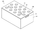
- FIG. 2 is a perspective view schematically showing the appearance of the battery module according to the first embodiment.
- FIG. 3 is a cross-sectional view taken along line III-III shown in FIG.
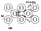
- FIG. 4 is a view showing a flow path of gas discharged from the open portion of the battery.
- FIG. 5 is a perspective view schematically showing the external appearance of the battery module according to the second embodiment.
- FIG. 1 is a cross-sectional view schematically showing a configuration of a battery 100 used in the battery module according to the first embodiment.
- the battery used in the battery module of the present invention may be a battery that can be used alone as a power source for a portable electronic device such as a notebook personal computer (hereinafter, the battery used in the battery module is referred to as “unit cell”). ").
- unit cell the battery used in the battery module
- a high-performance general-purpose battery can be used as a unit cell of the battery module, it is possible to easily improve the performance and cost of the battery module.
- the unit cell 100 used in the battery module of the present invention for example, a cylindrical lithium ion secondary battery as shown in FIG. 1 can be adopted.
- This lithium ion secondary battery is provided with a safety mechanism that releases the generated gas to the outside of the battery when the pressure in the battery increases due to an internal short circuit or the like.
- a specific configuration of the unit cell 100 will be described with reference to FIG.
- an electrode group 4 in which a positive electrode 1 and a negative electrode 2 are wound through a separator 3 is housed in a battery case 7 together with a non-aqueous electrolyte. Insulating plates 9 and 10 are arranged above and below the electrode group 4.
- the positive electrode 1 is bonded to the filter 12 via the positive electrode lead 5, and the negative electrode 2 is bonded to the bottom of the battery case 7 that also serves as the negative electrode terminal via the negative electrode lead 6.
- the filter 12 is connected to an inner cap 13, and the protrusion of the inner cap 13 is joined to a metal valve plate 14. Further, the valve plate 14 is connected to a terminal plate 8 that also serves as a positive electrode terminal. The terminal plate 8, the valve plate 14, the inner cap 13 and the filter 12 are integrated to seal the opening of the battery case 7 via the gasket 11.
- valve plate 14 When an internal short circuit occurs in the unit cell 100 and the pressure in the unit cell 100 increases, the valve plate 14 swells toward the terminal plate 8. When the valve plate 14 swells and the inner cap 13 and the valve plate 14 are disconnected from each other, the current path is interrupted. When the pressure in the unit cell 100 further increases, the valve plate 14 is broken. As a result, the gas generated in the unit cell 100 passes through the through hole 12 a of the filter 12, the through hole 13 a of the inner cap 13, the tear generated in the valve plate 14, and the external portion 8 a of the terminal plate 8. Is discharged.
- the safety mechanism for discharging the gas generated in the unit cell 100 to the outside is not limited to the structure shown in FIG.
- FIG. 2 is a perspective view schematically showing the external appearance of the battery module according to the first embodiment
- FIG. 3 is a cross-sectional view taken along the line III-III shown in FIG.
- the battery module 200 includes a housing 130, a plurality of unit cells 100 housed in the housing 130, a battery holding member 110 that holds the unit cells 100, and a housing 130. And a lid 120 attached to cover the opening.
- the housing 130 has a rectangular parallelepiped box shape with one surface open.
- a discharge port 131 for discharging the gas generated in the battery module 200 is provided in the opening side portion of the side surface.
- the housing 130 accommodates the plurality of unit cells 100 with each terminal plate 8 facing the opening.
- the battery holding member 110 has a plurality of battery housing portions 111 for housing a plurality of unit cells 100.
- the battery housing part 111 is a hole corresponding to the outer shape of the battery case 7, the inner diameter of the battery housing part 111 is substantially equal to the outer shape of the battery case 7, and the depth of the battery housing part 111 is the height of the outer peripheral wall of the battery case 7. Almost equal. Therefore, as shown in FIG. 3, when the unit cell 100 is inserted into the battery housing part 111, a part of the terminal plate 8 protrudes from the battery housing part 111, and the outer surface of the battery case 7 and the inner peripheral surface of the battery housing part 111 Will be in close contact.
- the battery holding member 110 When the unit cell 100 is held by the battery holding member 110 in this manner, when the gas is released from the open portion 8a of the unit cell 100, the released gas is at the upper end of the battery holding member 110, that is, the battery of the unit cell 100. Since it is prevented that the case 7 goes below the upper end of the side surface of the case 7, it is possible to prevent similar firing from the unit cell 100 that has exhausted the gas to another unit cell 100. Moreover, since the outer surface of the battery case 7 and the inner peripheral wall of the battery housing part 111 are in close contact with each other, the battery holding member 110 is made of a material having thermal conductivity, so that the battery holding member 110 can be used as a heat buffer. It is also possible to give this function.
- the lid 120 is a member that is attached so as to cover the opening of the housing 130, but also has a function as a current collector.
- the lid 120 is made of a conductive material, and includes a flat plate portion 121 and a plurality of spot-like convex portions 122 that protrude from the plane including the flat plate portion 121 toward the inner side of the housing 130.
- the plurality of spot-like convex portions 122 are provided in a distributed manner on the lid 120.
- a flat surface is formed at the tip of the convex portion 122, and the terminal plate 8 of the unit cell 100 is joined to the flat surface.
- the lid 120 and the battery holding member 110 containing the unit cells 100 are accommodated by a continuous space formed between the projections 122. Between the terminal plate 8 and the discharge port 131 on the side surface of the housing 130 is formed.
- the number of the unit cells 100 is equal to the number of the convex portions 122, and the unit cells 100 and the convex portions 122 have a one-to-one correspondence.
- FIG. 4 is a view showing a flow path of gas discharged from the open part of the battery.
- the gas does not easily pass through the connecting portion between the positive electrode terminal of the unit cell 100 and the convex portion 122 of the lid 120, and the gas is easily passed through the space between the convex portions 122. Therefore, as shown in FIG. 4, the gas discharged from the open part 8 a of a certain unit cell 100 is exhausted to the outside from the discharge port 131 of the housing 130 through the space formed in the convex part 122.
- a gas flow path can be formed in the upper part of the unit cell 100 by the structure of the lid body 120 for sealing the plurality of unit cells 100 in the housing 130.
- a highly safe battery module that can discharge high temperature gas discharged from an abnormal battery to the outside of the housing 130 while suppressing volume increase as much as possible can be realized.
- the lid 120 since the lid 120 also has a function as a current collector plate, it is suitable for a battery module that realizes a desired voltage and capacity using a plurality of unit cells 100.
- FIG. 5 is a perspective view schematically showing the external appearance of the battery module according to the second embodiment.
- the battery module 300 according to the present embodiment is different from the battery module 200 according to the first embodiment in terms of the shape of the lid 140. In the following description, differences between the present embodiment and the first embodiment will be mainly described.
- a plurality of spot-like convex portions 122 for connection to the unit cell 100 are provided in a dispersed manner, whereas in the lid body 140 according to the present embodiment, The linear convex part 142 which protrudes from the plane containing the flat plate part 141 is provided in stripe form, and the cover body 140 is formed in corrugated form.
- the positive electrode terminal of the unit cell 100 is connected to the tip surface of the convex portion 142 as in the first embodiment, but in this embodiment, a plurality of unit cells 100 are connected to one convex portion 142.
- the discharge port 131 provided in the housing 130 is provided over substantially the entire width direction of the housing 130.
- a flow path from the positive terminal of the unit cell 100 to the discharge port 131 of the housing 130 is formed by the space formed between the adjacent convex portions 142. Therefore, also with the configuration according to the present embodiment, it is possible to realize a highly safe battery module 300 that can discharge the high temperature gas discharged from the abnormal battery to the outside of the housing 130 while suppressing an increase in the volume of the battery module 300 as much as possible. Furthermore, in this embodiment, the linear space sandwiched between the adjacent convex portions 142 becomes a gas flow path that reaches the discharge port 131, but this gas flow path is shifted from the alignment position of the battery. The gas discharged from the battery is prevented from affecting other normal batteries.
- the lid since the lid also has a function as a current collector plate, the lid is formed of a conductive material.
- an insulating member for insulating the outer surface of the lid 120 is provided. Further, it may be provided.
- an insulating material may be coated on the outer surface of the lid 120 formed of a conductive material such as a copper plate, or the outer surface of the lid 120 may be covered with a resin insulating film. Moreover, it is good also as a clad material of a metal and resin.
- the number, size, and formation position of the discharge ports provided in the housing are arbitrary, and any gas can be used as long as the gas discharged from the abnormal battery can be quickly discharged outside the housing.
- the space formed between the convex portions can be used as a cooling channel for the battery module.
- the flow path extending from the inlet to the outlet through a space formed between the convex portions is provided with an inlet and an outlet for discharging the cooling medium in the housing or the lid.
- These inflow ports and discharge ports may also be used as the gas discharge ports at the time of abnormality described above.
- the spot-shaped or linear convex portion is exemplified, but the shape of the convex portion is not particularly limited as long as a flow path is formed between the convex portions.
- the present invention is useful as a power source for driving automobiles, electric motorcycles, electric playground equipment and the like.
Landscapes
- Chemical & Material Sciences (AREA)
- Chemical Kinetics & Catalysis (AREA)
- Electrochemistry (AREA)
- General Chemical & Material Sciences (AREA)
- Gas Exhaust Devices For Batteries (AREA)
- Battery Mounting, Suspending (AREA)
- Connection Of Batteries Or Terminals (AREA)
Abstract
Description
図1は、第1の実施形態に係る電池モジュールに使用される電池100の構成を模式的に示した断面図である。なお、本発明の電池モジュールに使用される電池は、ノート型パソコン等の携帯用電子機器の電源として単体でも使用できる電池であってもよい(以下、電池モジュールに使用する電池を、「素電池」と呼ぶ)。この場合、高性能の汎用電池を、電池モジュールの素電池として使用することができるため、電池モジュールの高性能化、低コスト化をより容易に図ることができる。
図5は、第2の実施形態に係る電池モジュールの外観を模式的に示した斜視図である。本実施形態に係る電池モジュール300は、蓋体140の形状の面で第1の実施形態に係る電池モジュール200と相違する。以下の説明では、本実施形態と第1の実施形態との相違点を中心に説明する。
尚、上記の各実施形態において、蓋体は集電板としての機能も兼ね備えているため、蓋体は導電性材料で形成されているが、蓋体120の外面を絶縁するための絶縁部材を更に設けても良い。例えば、銅板等の導電性材料により形成した蓋体120の外面に、絶縁材料をコーティングしたり、蓋体120の外面を樹脂製の絶縁膜で覆ったりしても良い。また、金属と樹脂のクラッド材としてもよい。
2 負極
3 セパレータ
4 電極群
5 正極リード
6 負極リード
7 電池ケース
8 端子板(正極端子)
8a 開放部
9、10 絶縁板
11 ガスケット
12 フィルタ
12a 貫通孔
13 インナーキャップ
13a 貫通孔
14 弁板
100 素電池
110 電池保持部材
120 蓋体
121 平板部
122 凸部
200 電池モジュール
130 筐体
131 排出口
140 蓋体
141 平板部
142 凸部
300 電池モジュール
Claims (6)
- 電池モジュールであって、
開口部と内部で発生したガスを排出する排出口とを有する筐体と、
内部で発生したガスを排出するための開放部が設けられた端子板を有し、前記端子板を前記開口部側に向けた状態で前記筐体の内部に配置される複数の電池と、
前記開口部を覆うように前記筐体に取り付けられ、平板部と、前記平板部を含む平面から前記筐体の内方側に突出して、前記電池の前記端子板に接続される複数の凸部とを有する蓋体とを備える、電池モジュール。 - 前記蓋体には、直線状の前記凸部がストライプ状に延びるように形成されており、
前記凸部の各々に対して、複数の前記電池の前記端子板が接続され、
前記平板部と前記凸部とで前記排気口に向かう排気路を形成する、請求項1に記載の電池モジュール。 - 前記蓋体には、前記電池の位置に対応してスポット状の前記凸部が分散して形成されており、
前記凸部の各々に対して、1つの前記電池の前記端子板が接続され、
前記平板部と前記凸部とで前記排気口に向かう排気路を形成する、請求項1に記載の電池モジュール。 - 前記筐体内に配置され、前記複数の電池の隙間を埋める電池保持部を更に備える、請求項2または3のいずれかに記載の電池モジュール。
- 前記蓋体は、前記複数の電池の端子板に電気接続されて、前記複数の電池を並列接続で集電する、請求項2または3のいずれかに記載の電池モジュール。
- 前記蓋体は、導電性を有する材料によって形成されており、
前記蓋体の外面を覆う絶縁性部材が更に設けられる、請求項5に記載の電池モジュール。
Priority Applications (3)
| Application Number | Priority Date | Filing Date | Title |
|---|---|---|---|
| JP2012517596A JP5033271B2 (ja) | 2010-07-29 | 2011-07-25 | 電池モジュール |
| CN2011800044466A CN102696132A (zh) | 2010-07-29 | 2011-07-25 | 电池模块 |
| US13/509,490 US20120225335A1 (en) | 2010-07-29 | 2011-07-25 | Battery module |
Applications Claiming Priority (2)
| Application Number | Priority Date | Filing Date | Title |
|---|---|---|---|
| JP2010-169997 | 2010-07-29 | ||
| JP2010169997 | 2010-07-29 |
Publications (1)
| Publication Number | Publication Date |
|---|---|
| WO2012014433A1 true WO2012014433A1 (ja) | 2012-02-02 |
Family
ID=45529666
Family Applications (1)
| Application Number | Title | Priority Date | Filing Date |
|---|---|---|---|
| PCT/JP2011/004177 Ceased WO2012014433A1 (ja) | 2010-07-29 | 2011-07-25 | 電池モジュール |
Country Status (5)
| Country | Link |
|---|---|
| US (1) | US20120225335A1 (ja) |
| JP (1) | JP5033271B2 (ja) |
| KR (1) | KR20120081198A (ja) |
| CN (1) | CN102696132A (ja) |
| WO (1) | WO2012014433A1 (ja) |
Cited By (3)
| Publication number | Priority date | Publication date | Assignee | Title |
|---|---|---|---|---|
| JP2020166992A (ja) * | 2019-03-28 | 2020-10-08 | 三洋電機株式会社 | 電池パック |
| WO2023162909A1 (ja) * | 2022-02-28 | 2023-08-31 | パナソニックIpマネジメント株式会社 | 蓄電モジュール |
| JP2024527297A (ja) * | 2022-01-25 | 2024-07-24 | エルジー エナジー ソリューション リミテッド | バッテリーパック及びそれを含む自動車 |
Families Citing this family (12)
| Publication number | Priority date | Publication date | Assignee | Title |
|---|---|---|---|---|
| JP5761164B2 (ja) * | 2012-11-30 | 2015-08-12 | トヨタ自動車株式会社 | 組電池 |
| JP6006134B2 (ja) * | 2013-02-08 | 2016-10-12 | トヨタ自動車株式会社 | 接続部材 |
| US9614210B2 (en) | 2014-09-30 | 2017-04-04 | Johnson Controls Technology Company | Battery module vent system and method |
| JP6606907B2 (ja) * | 2015-07-30 | 2019-11-20 | 株式会社Gsユアサ | 蓄電装置 |
| EP3319146B1 (en) * | 2016-11-04 | 2018-10-17 | Samsung SDI Co., Ltd. | Battery system |
| JP6504146B2 (ja) * | 2016-11-24 | 2019-04-24 | トヨタ自動車株式会社 | 車載電池パック |
| KR102390766B1 (ko) * | 2017-05-22 | 2022-04-26 | 삼성에스디아이 주식회사 | 이차 전지 |
| KR102913987B1 (ko) | 2019-10-18 | 2026-01-15 | 주식회사 엘지에너지솔루션 | 전지 모듈 및 이을 포함하는 전지 팩 |
| CN118749162A (zh) * | 2022-02-28 | 2024-10-08 | 松下知识产权经营株式会社 | 蓄电模块 |
| KR102927405B1 (ko) * | 2022-11-21 | 2026-02-12 | 주식회사 엘지에너지솔루션 | 안전성이 강화된 배터리 팩 |
| US20240204342A1 (en) * | 2022-12-15 | 2024-06-20 | Polestar Performance Ab | Methods and systems for burst valve battery cell ventilation |
| JP2026019322A (ja) * | 2024-07-26 | 2026-02-05 | トヨタ自動車株式会社 | 蓄電装置 |
Citations (5)
| Publication number | Priority date | Publication date | Assignee | Title |
|---|---|---|---|---|
| JP2004178909A (ja) * | 2002-11-26 | 2004-06-24 | Matsushita Electric Ind Co Ltd | 密閉式二次電池 |
| JP2006286357A (ja) * | 2005-03-31 | 2006-10-19 | Tdk Corp | バッテリ装置及びバッテリケース |
| JP2007027011A (ja) * | 2005-07-20 | 2007-02-01 | Sanyo Electric Co Ltd | 電源装置 |
| JP2010086798A (ja) * | 2008-09-30 | 2010-04-15 | Toshiba Corp | バッテリのガス排気構造 |
| JP2010140695A (ja) * | 2008-12-10 | 2010-06-24 | Panasonic Corp | 電池モジュールとそれを用いた集合電池モジュール |
Family Cites Families (4)
| Publication number | Priority date | Publication date | Assignee | Title |
|---|---|---|---|---|
| KR100614367B1 (ko) * | 2004-10-28 | 2006-08-21 | 삼성에스디아이 주식회사 | 이차 전지 |
| SE528555C2 (sv) * | 2005-04-01 | 2006-12-12 | Nilar Int Ab | Ett hölje för ett slutet batteri |
| US20100047673A1 (en) * | 2006-10-13 | 2010-02-25 | Yasushi Hirakawa | Battery pack and battery-mounted device |
| JP2008117756A (ja) * | 2006-10-13 | 2008-05-22 | Matsushita Electric Ind Co Ltd | 電池パック、及び電池搭載機器 |
-
2011
- 2011-07-25 CN CN2011800044466A patent/CN102696132A/zh active Pending
- 2011-07-25 KR KR1020127012004A patent/KR20120081198A/ko not_active Ceased
- 2011-07-25 WO PCT/JP2011/004177 patent/WO2012014433A1/ja not_active Ceased
- 2011-07-25 JP JP2012517596A patent/JP5033271B2/ja not_active Expired - Fee Related
- 2011-07-25 US US13/509,490 patent/US20120225335A1/en not_active Abandoned
Patent Citations (5)
| Publication number | Priority date | Publication date | Assignee | Title |
|---|---|---|---|---|
| JP2004178909A (ja) * | 2002-11-26 | 2004-06-24 | Matsushita Electric Ind Co Ltd | 密閉式二次電池 |
| JP2006286357A (ja) * | 2005-03-31 | 2006-10-19 | Tdk Corp | バッテリ装置及びバッテリケース |
| JP2007027011A (ja) * | 2005-07-20 | 2007-02-01 | Sanyo Electric Co Ltd | 電源装置 |
| JP2010086798A (ja) * | 2008-09-30 | 2010-04-15 | Toshiba Corp | バッテリのガス排気構造 |
| JP2010140695A (ja) * | 2008-12-10 | 2010-06-24 | Panasonic Corp | 電池モジュールとそれを用いた集合電池モジュール |
Cited By (6)
| Publication number | Priority date | Publication date | Assignee | Title |
|---|---|---|---|---|
| JP2020166992A (ja) * | 2019-03-28 | 2020-10-08 | 三洋電機株式会社 | 電池パック |
| JP7301271B2 (ja) | 2019-03-28 | 2023-07-03 | パナソニックエナジー株式会社 | 電池パック |
| JP2024527297A (ja) * | 2022-01-25 | 2024-07-24 | エルジー エナジー ソリューション リミテッド | バッテリーパック及びそれを含む自動車 |
| JP7715848B2 (ja) | 2022-01-25 | 2025-07-30 | エルジー エナジー ソリューション リミテッド | バッテリーパック及びそれを含む自動車 |
| WO2023162909A1 (ja) * | 2022-02-28 | 2023-08-31 | パナソニックIpマネジメント株式会社 | 蓄電モジュール |
| EP4489203A4 (en) * | 2022-02-28 | 2025-05-07 | Panasonic Intellectual Property Management Co., Ltd. | ENERGY STORAGE MODULE |
Also Published As
| Publication number | Publication date |
|---|---|
| KR20120081198A (ko) | 2012-07-18 |
| US20120225335A1 (en) | 2012-09-06 |
| CN102696132A (zh) | 2012-09-26 |
| JP5033271B2 (ja) | 2012-09-26 |
| JPWO2012014433A1 (ja) | 2013-09-12 |
Similar Documents
| Publication | Publication Date | Title |
|---|---|---|
| JP5033271B2 (ja) | 電池モジュール | |
| JP5589078B2 (ja) | 電池モジュール | |
| CN103931020B (zh) | 电池组 | |
| JP6004282B2 (ja) | 電池モジュール | |
| US8956747B2 (en) | Battery module | |
| US9537130B2 (en) | Battery module | |
| JP5364204B2 (ja) | 電池モジュール | |
| US20140178723A1 (en) | Battery block and battery module comprising same | |
| JP2013030384A (ja) | 電池ブロックおよび電池パック | |
| WO2012014398A1 (ja) | 電池モジュール及びそれを用いた電池パック | |
| WO2013001585A1 (ja) | 電池モジュール | |
| CN102484235A (zh) | 电池模块 | |
| KR20170140693A (ko) | 배터리 모듈 및 이를 포함하는 배터리 팩, 자동차 | |
| CN102473871A (zh) | 电池组 | |
| JP2013037873A (ja) | 電池モジュール | |
| JP2012212558A (ja) | 電池モジュール | |
| WO2013018305A1 (ja) | 電池ブロック | |
| JP2012234698A (ja) | 蓄電装置 | |
| JPWO2013161292A1 (ja) | 電池モジュール |
Legal Events
| Date | Code | Title | Description |
|---|---|---|---|
| 121 | Ep: the epo has been informed by wipo that ep was designated in this application |
Ref document number: 11812035 Country of ref document: EP Kind code of ref document: A1 |
|
| WWE | Wipo information: entry into national phase |
Ref document number: 2012517596 Country of ref document: JP |
|
| ENP | Entry into the national phase |
Ref document number: 20127012004 Country of ref document: KR Kind code of ref document: A |
|
| WWE | Wipo information: entry into national phase |
Ref document number: 13509490 Country of ref document: US |
|
| NENP | Non-entry into the national phase |
Ref country code: DE |
|
| 122 | Ep: pct application non-entry in european phase |
Ref document number: 11812035 Country of ref document: EP Kind code of ref document: A1 |