WO2012011532A1 - ヒューズブロック装置 - Google Patents
ヒューズブロック装置 Download PDFInfo
- Publication number
- WO2012011532A1 WO2012011532A1 PCT/JP2011/066592 JP2011066592W WO2012011532A1 WO 2012011532 A1 WO2012011532 A1 WO 2012011532A1 JP 2011066592 W JP2011066592 W JP 2011066592W WO 2012011532 A1 WO2012011532 A1 WO 2012011532A1
- Authority
- WO
- WIPO (PCT)
- Prior art keywords
- fuse block
- bus bar
- fusible link
- bolt
- electric wire
- Prior art date
- Legal status (The legal status is an assumption and is not a legal conclusion. Google has not performed a legal analysis and makes no representation as to the accuracy of the status listed.)
- Ceased
Links
Images



Classifications
-
- H—ELECTRICITY
- H01—ELECTRIC ELEMENTS
- H01H—ELECTRIC SWITCHES; RELAYS; SELECTORS; EMERGENCY PROTECTIVE DEVICES
- H01H85/00—Protective devices in which the current flows through a part of fusible material and this current is interrupted by displacement of the fusible material when this current becomes excessive
- H01H85/02—Details
- H01H85/36—Means for applying mechanical tension to fusible member
-
- H—ELECTRICITY
- H01—ELECTRIC ELEMENTS
- H01H—ELECTRIC SWITCHES; RELAYS; SELECTORS; EMERGENCY PROTECTIVE DEVICES
- H01H85/00—Protective devices in which the current flows through a part of fusible material and this current is interrupted by displacement of the fusible material when this current becomes excessive
- H01H85/54—Protective devices wherein the fuse is carried, held, or retained by an intermediate or auxiliary part removable from the base, or used as sectionalisers
-
- H—ELECTRICITY
- H01—ELECTRIC ELEMENTS
- H01H—ELECTRIC SWITCHES; RELAYS; SELECTORS; EMERGENCY PROTECTIVE DEVICES
- H01H85/00—Protective devices in which the current flows through a part of fusible material and this current is interrupted by displacement of the fusible material when this current becomes excessive
- H01H85/02—Details
- H01H85/04—Fuses, i.e. expendable parts of the protective device, e.g. cartridges
- H01H85/05—Component parts thereof
- H01H85/143—Electrical contacts; Fastening fusible members to such contacts
-
- H—ELECTRICITY
- H01—ELECTRIC ELEMENTS
- H01H—ELECTRIC SWITCHES; RELAYS; SELECTORS; EMERGENCY PROTECTIVE DEVICES
- H01H85/00—Protective devices in which the current flows through a part of fusible material and this current is interrupted by displacement of the fusible material when this current becomes excessive
- H01H85/02—Details
- H01H85/20—Bases for supporting the fuse; Separate parts thereof
-
- H—ELECTRICITY
- H01—ELECTRIC ELEMENTS
- H01H—ELECTRIC SWITCHES; RELAYS; SELECTORS; EMERGENCY PROTECTIVE DEVICES
- H01H85/00—Protective devices in which the current flows through a part of fusible material and this current is interrupted by displacement of the fusible material when this current becomes excessive
- H01H85/02—Details
- H01H85/20—Bases for supporting the fuse; Separate parts thereof
- H01H85/2045—Mounting means or insulating parts of the base, e.g. covers, casings
-
- H—ELECTRICITY
- H01—ELECTRIC ELEMENTS
- H01H—ELECTRIC SWITCHES; RELAYS; SELECTORS; EMERGENCY PROTECTIVE DEVICES
- H01H85/00—Protective devices in which the current flows through a part of fusible material and this current is interrupted by displacement of the fusible material when this current becomes excessive
- H01H85/02—Details
- H01H85/20—Bases for supporting the fuse; Separate parts thereof
- H01H85/205—Electric connections to contacts on the base
-
- H—ELECTRICITY
- H01—ELECTRIC ELEMENTS
- H01H—ELECTRIC SWITCHES; RELAYS; SELECTORS; EMERGENCY PROTECTIVE DEVICES
- H01H85/00—Protective devices in which the current flows through a part of fusible material and this current is interrupted by displacement of the fusible material when this current becomes excessive
- H01H85/02—Details
- H01H85/22—Intermediate or auxiliary parts for carrying, holding, or retaining fuse, co-operating with base or fixed holder, and removable therefrom for renewing the fuse
Definitions
- the present invention relates to a fuse block device for mounting a large number of fuses connected between a battery and an electric device.
- the fuse block device described in Patent Document 1 is a multi-type fusible link.
- the fusible link 100 includes a first fuse circuit component 101 that is a bus bar and a bus bar.
- the first fuse circuit constituting body 101 includes an elongated rectangular connecting plate portion, a plurality of female terminal portions 100T connected in a chain form via each fusible portion in the short direction of the connecting plate portion, and a plurality of others.
- the conductive flat plate material is integrally formed by pressing so as to include a screw-fixing terminal portion.
- the second fuse circuit structure 102 has the same configuration, and both are connected by a common terminal portion 103. Since each fusible part is located between the first fuse circuit constituent body 101 and the second fuse circuit constituent body 102, it cannot be seen in the first fuse circuit constituent body 101 in FIG. It has a narrow and crank shape, and a low-melting-point metal is caulked and fixed in the middle of the crank shape.
- the present invention has been made to solve these drawbacks, and even if a pattern in which a large number of circuits that are not actually used exist due to differences in vehicle grades or vehicle types, only necessary circuits are fusible with wires.
- the purpose of the present invention is to provide a fuse block device that eliminates waste due to differences in vehicle grade and vehicle type by inserting a link, and that does not require a full correction of the bus bar even when the circuit or rating is changed.
- a fuse block device comprising a bus bar, a fuse block attached to the bus bar, and a fusible link with electric wires, wherein the fusible link with electric wires has screw fastening terminals screwed with bolts.
- An electric wire connecting portion provided at one end and connected to the electric wire is provided at the other end, and a bulging portion containing a fusible body is provided between the screw fastening terminal and the electric wire connecting portion, and the screw fastening
- a bolt insertion hole through which a bolt used for a terminal is inserted is provided in the bus bar, a nut that engages with the bolt inserted into the bolt insertion hole is embedded in the fuse block on the back side of the bus bar, and the fusible link with the electric wire
- the fuse block has an accommodating portion for accommodating the bulging portion in a state where the screw terminal is fixed to the bus bar with a bolt. Formed fuse block device.
- the fuse block device is formed separately from an electrical junction box, the bus bar is provided with a power feeding section that receives power from the electrical junction box, and the plurality of bolts
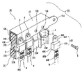
- FIG. 1 is a perspective view showing an HL (fusible link) mounting device and a fusible link in a fuse block device according to an embodiment of the present invention in a separated state, and an end portion is shown in a longitudinal section passing through a bolt insertion hole.
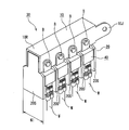
- ing. 2 is a perspective view showing a state in which the HL mounting device and the fusible link are separated from each other as in FIG. 1, and the end portion is shown in a longitudinal section from which the bolt insertion hole is removed.
- FIG. 3 is a perspective view showing a state in which four fusible links with electric wires are attached to the HL attachment device shown in FIG. 4A is a perspective view of the electrical junction box showing a state before the fuse block device shown in FIG.
- FIG. 3 is connected to the relay inner block
- FIG. 4B is a diagram showing the connection of the fuse block device to the relay inner block. It is a perspective view of the electrical junction box which shows the state after having done.
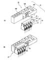
- FIGS. 5A to 5C are perspective views showing electrical junction boxes having different numbers of loads to be connected.
- FIG. 6 is an exploded perspective view of the fuse block device described in Patent Document 1. In FIG.
- an HL mounting device 30 to which an arbitrary number of fusible links 40 with electric wires can be mounted includes a bus bar 10 and a fuse block 20 mounted on the bus bar 10.
- the fuse block device 50 (FIG. 4) is completed. That is, the fuse block device 50 according to the present embodiment includes the HL mounting device 30 including the bus bar 10 and the fuse block 20 mounted on the bus bar 10, and the fusible link 40 with electric wires.
- bus bar 10 is formed by pressing a long conductive metal plate into a U-shaped cross section, and a plurality of bolt insertion holes 10B are opened at predetermined intervals in the longitudinal direction of the U-shaped open leg portion 10K.
- the terminal portion 10J is formed at the end of the long conductive metal plate.
- the end of the fuse block 20 is attached between the two open leg portions 10K having a U-shaped cross section.
- the thickness of the fuse block 20 is, as viewed in a longitudinal sectional view, the upper portion 20K (see FIG. 2), that is, the back side portion of the open leg portion 10K of the bus bar 10 is wide, and the lower portion 20W is also different from the upper portion 20K. It is also wide.
- the intermediate part 20N in the meantime is narrower than the upper part 20K and the lower part 20W.
- the vertical length of the intermediate portion 20N is equal to the vertical length of the bulging portion 40N that is resin-molded into a rectangular parallelepiped shape of the fusible link 40 with electric wires, and the lateral width (thickness) of the intermediate portion 20N.
- the portion formed by the difference from the width of the lower portion 20W can accommodate the predetermined length of the lateral width of the rectangular parallelepiped bulged portion 40N of the fusible link 40 with electric wire. Therefore, as a whole, as shown by a two-dot chain line circle A in FIG. 2, a depression (accommodating portion) D that can accommodate one surface of the bulging portion 40N of the rectangular parallelepiped resin of the fusible link 40 with electric wires is formed. . Further, a corner 20C is formed at a corner of the recess D of the fuse block 20 (a portion indicated by a two-dot chain line circle B in FIG.
- a corner of a rectangular parallelepiped bulging portion 40N of the fusible link 40 with electric wires A corner 40C is formed at the end. Therefore, the corner 40C of the fusible link 40 with electric wire is caught on the corner 20C of the fuse block 20.
- a nut N (see FIG. 1) that engages with the bolt B inserted into the bolt insertion hole 10B is embedded in the upper portion 20K (see FIG. 2) of the fuse block 20.
- the fusible link 40 with electric wire includes a screw terminal 40T having a screw hole 40B screwed with a bolt B (see FIG. 1) at one end, and crimps, spot welds, or ultrasonically connects the electric wire W (see FIG. 1). Is provided at the other end with a wire connecting portion 40W connected to the electric wire W, and a bulging portion 40N in which a fusible body is housed.
- the bulging portion 40N has a rectangular parallelepiped shape formed by injection molding of resin, and a corner facing the lower fuse block 20 is formed in a corner shape 40C.
- the electric wires W connected to the electric wire connecting portion 40W are connected to the respective loads.
- Attachment of the fusible link 40 with electric wires to the HL attachment device 30 is as follows.
- the bolt B is inserted into the screw hole 40B of the screw fastening terminal 40T of the fusible link 40 with electric wire, and the bolt B is inserted into the bolt insertion hole 10B of the bus bar 10 and screwed.
- the fusible link 40 with electric wire is fixed to the bus bar 10 by being screwed into a nut N (see FIG. 1) embedded in the upper portion 20K (see FIG. 2) of the fuse block 20.
- the bus bar 10 has a plurality of bolt insertion holes 10B (in FIG. 1, a total of 8 bolts on the front leg of the U-shaped leg of the bus bar 10 and 4 on the opposite side). A single fusible link 40 with electric wires can be attached, and a multi-structure can be obtained.
- FIG. 2 shows a state where two fusible links 40 with electric wires are attached to the HL attachment device 30.
- a plurality of bolt insertion holes 10B are formed in the bus bar 10 according to the present embodiment, a multi-structure in which a maximum of eight fusible links with electric wires 40 can be obtained. If there is a pattern in which there are many circuits that are not actually used due to differences in vehicle grade or vehicle type, the fusible link 40 with electric wires may not be attached to the bolt insertion hole 10B of the bus bar 10 connected to the circuit. . Further, even when changing the circuit or rating, according to the present embodiment, it is not necessary to modify the entire bus bar, and the fusible link 40 with an electric wire may be attached only to the bolt insertion hole 10B connected to the necessary circuit.
- FIG. 3 shows a state where four fusible links 40 with electric wires are attached to the HL attachment device 30.
- Insulating partition plates 20S are provided between the fusible links 40 with electric wires of the HL mounting device 30 or at end portions thereof to insulate each other.
- the fuse block 20 has a space for storing the fusible link 40 with the electric wire, this portion serves to prevent the element portion from being damaged by the external tension transmitted from the electric wire W to the fusible link 40. ing.
- the electrical junction box 70 includes a relay inner block 60 as shown in FIG. 4A and a fuse block device 50 shown in FIG.
- the relay inner block 60 is equipped with an electronic control device of a relay 60R inside, and these are connected to an external load via a fusible link 60B and a fuse F.
- 4A is an inner block bus bar for fastening the fuse block bus bar.
- the terminal block 10J of the bus bar 10 of the fuse block device 50 according to the present embodiment is connected to the inner block bus bar BA in FIG. 4B.
- FIG. 5 is a perspective view for explaining that an unused fusible link does not occur according to the fuse block device 50 of the present embodiment even if the number of loads connected to the electrical junction box is different.
- FIG. 5A shows an electric junction box 70A to which two loads are connected. By using only the fusible links 40-1 and 40-2 with wires according to the present embodiment, an unused fusible link is used. There is no link.
- FIG. 5B shows an electric junction box 70B to which three loads are connected. By using only the three fusible links 40-1, 40-2, and 40-3 with wires according to the present embodiment, There is no fusible link to use.
- FIG. 5A shows an electric junction box 70A to which two loads are connected. By using only the fusible links 40-1 and 40-2 with wires according to the present embodiment, an unused fusible link is used. There is no link.
- FIG. 5B shows an electric junction box 70B to which three loads are connected. By using only the three fusible links 40-1, 40-2,
- 5C shows an electric connection box 70C to which four loads are connected, and only four fusible links 40-1, 40-2, 40-3, and 40-4 with electric wires according to the present embodiment are used. As a result, an unusable fusible link does not occur.
- up to eight fusible links with electric wires can be used in the same manner, so that no unused fusible links are generated. Since all of the conventional electrical junction boxes were equipped with 8 fuses, an unused fuse was generated and wasted, but according to this embodiment, the fusible link 40-1 to 40 with wires Up to eight of 40-8 can be freely attached, and a necessary number of fusible links need only be attached, so that useless fusible links do not occur.
- the example of eight fusible links has been described. However, the number is merely limited to a specific number used for convenience of description, and is not limited to this number.
- the fuse block device of the present invention even if a pattern in which many circuits that are not actually used exist due to the difference in vehicle grade or vehicle type, waste due to the difference in vehicle grade or vehicle type can be eliminated, and the circuit A fuse block device that does not require modification of the entire bus bar even when the rating is changed can be obtained.
- Busbar 10B Bolt insertion hole 10J Terminal part (power feeding part) 10K Open leg 20 Fuse block 20C Corner of dent 20K Upper part 20N Intermediate part 20S Insulating partition plate 20W Lower part 30 HL mounting device 40 Fusible link with electric wire 40B Screw hole 40C Corner of bulge part 40N bulging part 40T screw terminal 40W electric wire connection part 50 fuse block device 60 relay inner block 60R internal relay 60B internal fusible link 70 electric connection box B bolt D dent (accommodating part) F Internal fuse N Nut W Electric wire
Landscapes
- Fuses (AREA)
Abstract
Description
特許文献1記載のヒューズブロック装置はマルチタイプのヒュージブルリンクであって、図6に分解斜視図で示すように、ヒュージブルリンク100は、バスバーである第1ヒューズ回路構成体101と、同じくバスバーである第2ヒューズ回路構成体102と、これらヒューズ回路構成体101、102が互いに所定の間隔を開けて組み込まれる合成樹脂製のハウジングHとを備えている。
第1ヒューズ回路構成体101は、細長い長方形状の連結プレート部と、この連結プレート部の短手方向に各可溶体部を介して連鎖状に連結された複数の雌端子部100Tと、その他複数のビス止め用端子部等とを備えるように、導電性平板状プレート材をプレス加工することにより一体に形成されている。第2ヒューズ回路構成体102も同様の構成で、両者は共通端子部103で繋がっている。
各可溶体部は第1ヒューズ回路構成体101と第2ヒューズ回路構成体102の間に位置しているので、図6では第1ヒューズ回路構成体101に隠れて見えないが、周知のように細幅でクランク状を有し、そのクランク形状の途中に低融点金属が加締め固定され、それぞれに所定値以上の電流が通電されると溶断されるようになっている。
従来公知のマルチタイプヒュージブルリンクはマルチ構造となったため、多種のヒューズがバスバーで一体に形成される。それ故、車輌グレードや車種の違いにより実際には使用しない回路が多数存在してしまうパターンが発生し、車種によっては半分以下の回路しか使用されないことがおきる可能性があった。
また、回路や定格変更の際には一体になったバスバーを設計変更する必要があり、一体型のバスバー構造のため空き回路の発生・定格変更等でのバスバー全面修正が必要になり、したがってワイヤハーネスの設計自由度を下げていた。
本発明はこれらの欠点を解決するためになされたもので、車輌グレードや車種の違いにより実際には使用しない回路が多数存在してしまうパターンが発生しても、必要な回路のみ電線付きヒュージブルリンクを入れることによって車輌グレードや車種の違いによる無駄が省け、また、回路や定格変更の際にもバスバー全面修正を必要としないヒューズブロック装置を提供することを目的としている。
(1) バスバーと、前記バスバーに取り付けられたヒューズブロックと、電線付きヒュージブルリンクとを備えたヒューズブロック装置であって、前記電線付きヒュージブルリンクは、ボルトでねじ締めされるねじ締め端子が一端に設けられ、電線と接続された電線接続部が他端に設けられ、可溶体を収容した膨出部が前記ねじ締め端子と前記電線接続部との間に設けられて成り、前記ねじ締め端子に用いるボルトを挿通するボルト挿通孔が前記バスバーに設けられ、前記ボルト挿通孔に挿通されたボルトと噛み合うナットが前記バスバーの裏側の前記ヒューズブロックに埋め込まれ、かつ、前記電線付きヒュージブルリンクのねじ締め端子が前記バスバーにボルトで固定された状態で前記膨出部を収容する収容部が前記ヒューズブロックに形成されたヒューズブロック装置。
(2) 上記(1)の構成のヒューズブロック装置において、前記ヒューズブロック装置は電気接続箱と別体で形成され、前記バスバーは前記電気接続箱からの給電を得る給電部と、複数の前記ボルト挿通孔とを備え、前記ヒューズブロックは複数の前記収容部を備えたヒューズブロック装置。
以下、車輌グレードや車種の違いがあっても使用しない回路が出ることのない、また、回路や定格変更の際にもバスバー全面修正が必要とならない本発明の一実施形態に係るヒューズブロック装置について、図1および図2を用いて説明する。
図1および図2において、任意個数の電線付きヒュージブルリンク40を取り付けることのできるHL取り付け装置30は、バスバー10とバスバー10に取り付けられたヒューズブロック20とから構成されている。このHL取り付け装置30に電線付きヒュージブルリンク40を取り付けると、ヒューズブロック装置50(図4)が出来上がる。すなわち、本実施形態に係るヒューズブロック装置50は、バスバー10とバスバー10に取り付けられたヒューズブロック20とからなるHL取り付け装置30と、電線付きヒュージブルリンク40と、から成っている。
バスバー10は長尺状の導電性金属板を断面コ字状にプレス加工したもので、断面コ字状の開脚部10Kの長手方向に複数個のボルト挿通孔10Bが所定間隔をおいて開けられ、長尺状の導電性金属板の端部に端子部10Jが形成されている。断面コ字状の両開脚部10Kの間にヒューズブロック20の端部が取り付けられている。
ヒューズブロック20の厚みは、縦断面図で見ると、上方部20K(図2参照)、すなわち、バスバー10の開脚部10Kの裏側部が幅広となっており、下方部20Wも上方部20Kと同じく幅広となっている。その間の中間部20Nは、上方部20Kおよび下方部20Wと比べて幅狭となっている。中間部20Nの上下方向の長さは、電線付きヒュージブルリンク40の直方体状に樹脂成形されている膨出部40Nの上下方向長さに等しく、また、中間部20Nの横方向の幅(厚さ)は、下方部20Wの幅との差で形成される部位が、電線付きヒュージブルリンク40の直方体状の膨出部40Nの横幅の所定長さを収容できるようになっている。したがって、全体で、図2の二点鎖線円Aで示すように、電線付きヒュージブルリンク40の直方体樹脂の膨出部40Nの一面を収容することのできる窪み(収容部)Dが形成される。
また、ヒューズブロック20の窪みDの角に角20Cが(図2の二点鎖線円Bで示す部分)形成されており、一方、電線付きヒュージブルリンク40の直方体状の膨出部40Nの角に角40Cが形成されている。そこで、このヒューズブロック20の角20Cに電線付きヒュージブルリンク40の角40Cが引っ掛かるようになる。
そして、ヒューズブロック20の上方部20K(図2参照)には、ボルト挿通孔10Bに挿通されたボルトBと噛み合うナットN(図1参照)が埋め込まれている。
電線付きヒュージブルリンク40は、ボルトB(図1参照)でねじ締めされるねじ孔40Bを有するねじ締め端子40Tを一端に備え、電線W(図1参照)を圧着・スポット溶接又は超音波接続により電線Wと接続された電線接続部40Wを他端に備え、可溶体を内部に収容した膨出部40Nを中間に備えている。膨出部40Nは樹脂を射出成型して成る直方体の形状をしており、下方のヒューズブロック20側に面する隅を角(かど)状40Cに形成している。
電線接続部40Wに接続された電線Wはそれぞれ各負荷に繋がっている。
HL取り付け装置30への電線付きヒュージブルリンク40の取り付けは次のようになる。電線付きヒュージブルリンク40のねじ締め端子40Tのねじ孔40BにボルトBを挿通し、そのボルトBをバスバー10のボルト挿通孔10Bに挿通し、ねじ締めする。すると、ヒューズブロック20の上方部20K(図2参照)に埋め込まれたナットN(図1参照)にねじ込まれて、電線付きヒュージブルリンク40はバスバー10に固定される。この状態で、電線付きヒュージブルリンク40の膨出部40Nは、ヒューズブロック20の中間部20Nである窪みDに一部が収容されて、膨出部40Nはヒューズブロック20に安定して固定されるようになる。このとき電線付きヒュージブルリンク40の直方体状の膨出部40Nの角40Cがヒューズブロック20の中間部20Nの角20Cに引っ掛かるようになるので、電線付きヒュージブルリンク40はHL取り付け装置30へいっそう安定して取り付けられることとなる。
バスバー10にはボルト挿通孔10Bが複数個(図1ではバスバー10のコ字状脚部の手前側脚部に4個、反対側に4個の合計8個)あけられているので、最大8個の電線付きヒュージブルリンク40を取り付けることができ、マルチ構造とすることができる。
図2は電線付きヒュージブルリンク40が2個、HL取り付け装置30へ取り付けられた状態を示している。上記のように、本実施形態に係るバスバー10にはボルト挿通孔10Bが複数個あけられているので、最大8個の電線付きヒュージブルリンク40を取り付けることができるマルチ構造が得られる。
車輌グレードや車種の違いにより実際には使用しない回路が多数存在してしまうパターンが発生した場合には、その回路に繋がるバスバー10のボルト挿通孔10Bに電線付きヒュージブルリンク40を取り付けなければよい。
また、回路や定格変更の際にも、本実施形態によればバスバー全面修正が必要でなく、必要な回路に繋がるボルト挿通孔10Bにのみ電線付きヒュージブルリンク40を取り付ければよい。
図3は電線付きヒュージブルリンク40が4個、HL取り付け装置30へ取り付けられた状態を示している。HL取り付け装置30の電線付きヒュージブルリンク40同士の間や端部には、絶縁仕切板20Sを設けて互いの電気絶縁を行っている。
この絶縁仕切板20Sの横幅W1を、従来のマルチFLと同等の幅とすることで従来のマルチFLと同等のスペースで同極数を構成することが可能となり、従来技術のマルチFLの役目を果たす部品とすることができる。
ヒューズブロック20には電線付きヒュージブルリンク40が収納される空間があるので、この部分が、電線Wからヒュージブルリンク40に伝わる外部からのテンションによりエレメント部分が破損することを防止する役目をしている。
本実施形態に係る電気接続箱70は、図4(A)に示すようなリレーインナーブロック60と図3に示したヒューズブロック装置50とから成る。リレーインナーブロック60には、内部にリレー60Rの電子制御装置が装備され、これらはヒュージブルリンク60B、ヒューズFを介して外部の負荷と接続される。図4(A)の符号BAはヒューズブロックバスバー締結用のインナーブロックバスバーで、このインナーブロックバスバーBAに本実施形態に係るヒューズブロック装置50のバスバー10の端子部10Jが、図4(B)のように接続されることで、本実施形態に係るヒューズブロック装置50に接続されているすべての負荷がヒューズFを介してリレーインナーブロック60に通電可能に接続される。
図5(A)は2個の負荷が接続される電気接続箱70Aで、本実施形態による電線付きヒュージブルリンク40-1と40-2の2個のみを用いることで、不使用のヒュージブルリンクが生じない。
図5(B)は3個の負荷が接続される電気接続箱70Bで、本実施形態による電線付きヒュージブルリンク40-1と40-2と40-3の3個のみを用いることで、不使用のヒュージブルリンクが生じない。
図5(C)は4個の負荷が接続される電気接続箱70Cで、本実施形態による電線付きヒュージブルリンク40-1と40-2と40-3と40-4の4個のみを用いることで、不使用のヒュージブルリンクが生じない。
以上、同じようにして8個までの電線付きヒュージブルリンクを用いることができ、これにより不使用のヒュージブルリンクが生じない。
従来の電気接続箱にはすべて8個のヒューズが取り付けられていたので、不使用のヒューズが発生して、無駄が起こったが、本実施形態によれば、電線付きヒュージブルリンク40-1~40-8の8個まで自由に取り付けることができ、必要な数のヒュージブルリンクを取り付ければよいので、無駄なヒュージブルリンクが生じなくなる。
なお、以上の説明では8個のヒュージブルリンクの例で説明したが、説明の便宜のために使った具体的な数で説明しただけで、この数にもちろん限定されるものではない。
なお、本出願は、2010年7月23日出願の日本特許出願(特願2010-166403)に基づくものであり、その内容はここに参照して取り込まれる。
10B ボルト挿通孔
10J 端子部(給電部)
10K 開脚部
20 ヒューズブロック
20C 窪みの角(かど)
20K 上方部
20N 中間部
20S 絶縁仕切板
20W 下方部
30 HL取り付け装置
40 電線付きヒュージブルリンク
40B ねじ孔
40C 膨出部の角(かど)
40N 膨出部
40T ねじ締め端子
40W 電線接続部
50 ヒューズブロック装置
60 リレーインナーブロック
60R 内部リレー
60B 内部ヒュージブルリンク
70 電気接続箱
B ボルト
D 窪み(収容部)
F 内部ヒューズ
N ナット
W 電線
Claims (2)
- バスバーと、前記バスバーに取り付けられたヒューズブロックと、電線付きヒュージブルリンクとを備えたヒューズブロック装置であって、
前記電線付きヒュージブルリンクは、ボルトでねじ締めされるねじ締め端子が一端に設けられ、電線と接続された電線接続部が他端に設けられ、可溶体を収容した膨出部が前記ねじ締め端子と前記電線接続部との間に設けられて成り、
前記ねじ締め端子に用いるボルトを挿通するボルト挿通孔が前記バスバーに設けられ、
前記ボルト挿通孔に挿通されたボルトと噛み合うナットが前記バスバーの裏側の前記ヒューズブロックに埋め込まれ、かつ、前記電線付きヒュージブルリンクのねじ締め端子が前記バスバーにボルトで固定された状態で前記膨出部を収容する収容部が前記ヒューズブロックに形成されたヒューズブロック装置。 - 前記ヒューズブロック装置は電気接続箱と別体で形成され、
前記バスバーは前記電気接続箱からの給電を得る給電部と、複数の前記ボルト挿通孔とを備え、
前記ヒューズブロックは複数の前記収容部を備えた請求項1記載のヒューズブロック装置。
Priority Applications (4)
| Application Number | Priority Date | Filing Date | Title |
|---|---|---|---|
| KR1020137001844A KR101417689B1 (ko) | 2010-07-23 | 2011-07-21 | 휴즈 블럭 장치 |
| DE112011102449T DE112011102449T5 (de) | 2010-07-23 | 2011-07-21 | Sicherungsblockvorrichtung |
| CN201180036191.1A CN103026448B (zh) | 2010-07-23 | 2011-07-21 | 熔丝盒装置 |
| US13/811,422 US20130120101A1 (en) | 2010-07-23 | 2011-07-21 | Fuse block device |
Applications Claiming Priority (2)
| Application Number | Priority Date | Filing Date | Title |
|---|---|---|---|
| JP2010166403A JP5606200B2 (ja) | 2010-07-23 | 2010-07-23 | ヒューズブロック装置 |
| JP2010-166403 | 2010-07-23 |
Publications (1)
| Publication Number | Publication Date |
|---|---|
| WO2012011532A1 true WO2012011532A1 (ja) | 2012-01-26 |
Family
ID=45496950
Family Applications (1)
| Application Number | Title | Priority Date | Filing Date |
|---|---|---|---|
| PCT/JP2011/066592 Ceased WO2012011532A1 (ja) | 2010-07-23 | 2011-07-21 | ヒューズブロック装置 |
Country Status (6)
| Country | Link |
|---|---|
| US (1) | US20130120101A1 (ja) |
| JP (1) | JP5606200B2 (ja) |
| KR (1) | KR101417689B1 (ja) |
| CN (1) | CN103026448B (ja) |
| DE (1) | DE112011102449T5 (ja) |
| WO (1) | WO2012011532A1 (ja) |
Families Citing this family (6)
| Publication number | Priority date | Publication date | Assignee | Title |
|---|---|---|---|---|
| JP6287891B2 (ja) * | 2015-02-24 | 2018-03-07 | 株式会社オートネットワーク技術研究所 | 電気接続箱及び接続端子部品 |
| JP6490729B2 (ja) * | 2017-03-22 | 2019-03-27 | 矢崎総業株式会社 | 電気接続箱 |
| EP3613068B1 (en) * | 2017-04-18 | 2021-11-03 | Delphi Technologies, Inc. | Fuse assembly |
| KR102344019B1 (ko) * | 2019-12-23 | 2021-12-28 | 대산전자(주) | 퓨즈가 적용된 버스바 |
| US11211220B1 (en) * | 2020-07-16 | 2021-12-28 | Sumitomo Wiring Systems, Ltd. | Fuse array and junction box with fuse array |
| EP4064319B1 (en) * | 2021-03-24 | 2025-04-02 | Littelfuse, Inc. | Attaching an isolated single stud fuse to an electrical device |
Citations (4)
| Publication number | Priority date | Publication date | Assignee | Title |
|---|---|---|---|---|
| JPH0198458U (ja) * | 1987-12-22 | 1989-06-30 | ||
| JPH10188774A (ja) * | 1996-12-27 | 1998-07-21 | Yazaki Corp | ヒューズボックスのバスバー固定構造 |
| JP2006107965A (ja) * | 2004-10-06 | 2006-04-20 | Yazaki Corp | ヒューズブロック |
| JP2009087769A (ja) * | 2007-09-28 | 2009-04-23 | Yazaki Corp | ヒューズプラーおよび電気接続箱 |
Family Cites Families (8)
| Publication number | Priority date | Publication date | Assignee | Title |
|---|---|---|---|---|
| US4722701A (en) * | 1986-09-29 | 1988-02-02 | Todd Engineering Sales, Inc. | Fuse block for miniature plug-in blade-type fuse |
| JP2613400B2 (ja) * | 1987-10-12 | 1997-05-28 | 株式会社中埜酢店 | 醸造用原料の製造法 |
| US5643693A (en) * | 1995-10-30 | 1997-07-01 | Yazaki Corporation | Battery-mounted power distribution module |
| JP4091181B2 (ja) * | 1998-10-27 | 2008-05-28 | 矢崎総業株式会社 | 連鎖型大電流ヒュージブルリンク |
| JP3516259B2 (ja) * | 1999-05-18 | 2004-04-05 | 矢崎総業株式会社 | 電源直付け用大電流ヒューズ |
| JP4112936B2 (ja) * | 2002-10-02 | 2008-07-02 | 矢崎総業株式会社 | ヒュージブルリンクユニット |
| JP5294402B2 (ja) * | 2008-10-23 | 2013-09-18 | 矢崎総業株式会社 | 電気接続箱 |
| JP2010166403A (ja) * | 2009-01-16 | 2010-07-29 | Sony Corp | パルス分離回路 |
-
2010
- 2010-07-23 JP JP2010166403A patent/JP5606200B2/ja active Active
-
2011
- 2011-07-21 CN CN201180036191.1A patent/CN103026448B/zh active Active
- 2011-07-21 KR KR1020137001844A patent/KR101417689B1/ko not_active Expired - Fee Related
- 2011-07-21 US US13/811,422 patent/US20130120101A1/en not_active Abandoned
- 2011-07-21 WO PCT/JP2011/066592 patent/WO2012011532A1/ja not_active Ceased
- 2011-07-21 DE DE112011102449T patent/DE112011102449T5/de not_active Ceased
Patent Citations (4)
| Publication number | Priority date | Publication date | Assignee | Title |
|---|---|---|---|---|
| JPH0198458U (ja) * | 1987-12-22 | 1989-06-30 | ||
| JPH10188774A (ja) * | 1996-12-27 | 1998-07-21 | Yazaki Corp | ヒューズボックスのバスバー固定構造 |
| JP2006107965A (ja) * | 2004-10-06 | 2006-04-20 | Yazaki Corp | ヒューズブロック |
| JP2009087769A (ja) * | 2007-09-28 | 2009-04-23 | Yazaki Corp | ヒューズプラーおよび電気接続箱 |
Also Published As
| Publication number | Publication date |
|---|---|
| JP2012028191A (ja) | 2012-02-09 |
| US20130120101A1 (en) | 2013-05-16 |
| DE112011102449T5 (de) | 2013-06-20 |
| KR101417689B1 (ko) | 2014-07-09 |
| JP5606200B2 (ja) | 2014-10-15 |
| CN103026448B (zh) | 2015-05-20 |
| CN103026448A (zh) | 2013-04-03 |
| KR20130059386A (ko) | 2013-06-05 |
Similar Documents
| Publication | Publication Date | Title |
|---|---|---|
| US6830482B2 (en) | Fusible link and method of producing said fusible link | |
| JP4917927B2 (ja) | 車両用多連型ヒューズ装置 | |
| CN101183772B (zh) | 电接线盒 | |
| KR101461300B1 (ko) | 퓨즈 유닛 | |
| US20040130430A1 (en) | Fusible link unit | |
| US7347733B2 (en) | Electric junction box | |
| JP5606200B2 (ja) | ヒューズブロック装置 | |
| US9589756B2 (en) | Fusible link mounting structure and electrical junction box | |
| JP4096431B2 (ja) | 多連ヒューズ素子および該多連ヒューズ素子を用いた多連ヒューズ | |
| US20110100706A1 (en) | Electric junction box | |
| JP4828944B2 (ja) | 電気接続箱 | |
| KR20160031531A (ko) | 배터리 직접 장착 퓨저블 링크 | |
| CN104603905A (zh) | 保险丝装置及其制造方法 | |
| JP6823633B2 (ja) | バスバー組み付け構造、電気接続箱、及びワイヤハーネス | |
| JP4456519B2 (ja) | 電気接続箱 | |
| JP2012010590A (ja) | 電気接続箱 | |
| JP4112936B2 (ja) | ヒュージブルリンクユニット | |
| WO2021006109A1 (ja) | 電気接続箱 | |
| JP2007179978A (ja) | ヒュージブルリンクユニット | |
| JP2006149077A (ja) | 電気接続箱 | |
| JP7495255B2 (ja) | 電気接続箱 | |
| JP2004186005A (ja) | ヒュージブルリンクユニット | |
| JP7680280B2 (ja) | ヒューズユニット | |
| JP7283369B2 (ja) | 電気接続箱 | |
| JP4870999B2 (ja) | 多極ヒューズ |
Legal Events
| Date | Code | Title | Description |
|---|---|---|---|
| WWE | Wipo information: entry into national phase |
Ref document number: 201180036191.1 Country of ref document: CN |
|
| 121 | Ep: the epo has been informed by wipo that ep was designated in this application |
Ref document number: 11809702 Country of ref document: EP Kind code of ref document: A1 |
|
| WWE | Wipo information: entry into national phase |
Ref document number: 13811422 Country of ref document: US |
|
| ENP | Entry into the national phase |
Ref document number: 20137001844 Country of ref document: KR Kind code of ref document: A |
|
| WWE | Wipo information: entry into national phase |
Ref document number: 112011102449 Country of ref document: DE Ref document number: 1120111024495 Country of ref document: DE |
|
| 122 | Ep: pct application non-entry in european phase |
Ref document number: 11809702 Country of ref document: EP Kind code of ref document: A1 |