WO2012011531A1 - 送電装置及び送受電システム - Google Patents
送電装置及び送受電システム Download PDFInfo
- Publication number
- WO2012011531A1 WO2012011531A1 PCT/JP2011/066590 JP2011066590W WO2012011531A1 WO 2012011531 A1 WO2012011531 A1 WO 2012011531A1 JP 2011066590 W JP2011066590 W JP 2011066590W WO 2012011531 A1 WO2012011531 A1 WO 2012011531A1
- Authority
- WO
- WIPO (PCT)
- Prior art keywords
- power
- power transmission
- unit
- magnetic field
- reception
- Prior art date
- Legal status (The legal status is an assumption and is not a legal conclusion. Google has not performed a legal analysis and makes no representation as to the accuracy of the status listed.)
- Ceased
Links
Images



Classifications
-
- H—ELECTRICITY
- H04—ELECTRIC COMMUNICATION TECHNIQUE
- H04B—TRANSMISSION
- H04B5/00—Near-field transmission systems, e.g. inductive or capacitive transmission systems
- H04B5/70—Near-field transmission systems, e.g. inductive or capacitive transmission systems specially adapted for specific purposes
- H04B5/79—Near-field transmission systems, e.g. inductive or capacitive transmission systems specially adapted for specific purposes for data transfer in combination with power transfer
-
- B—PERFORMING OPERATIONS; TRANSPORTING
- B60—VEHICLES IN GENERAL
- B60L—PROPULSION OF ELECTRICALLY-PROPELLED VEHICLES; SUPPLYING ELECTRIC POWER FOR AUXILIARY EQUIPMENT OF ELECTRICALLY-PROPELLED VEHICLES; ELECTRODYNAMIC BRAKE SYSTEMS FOR VEHICLES IN GENERAL; MAGNETIC SUSPENSION OR LEVITATION FOR VEHICLES; MONITORING OPERATING VARIABLES OF ELECTRICALLY-PROPELLED VEHICLES; ELECTRIC SAFETY DEVICES FOR ELECTRICALLY-PROPELLED VEHICLES
- B60L53/00—Methods of charging batteries, specially adapted for electric vehicles; Charging stations or on-board charging equipment therefor; Exchange of energy storage elements in electric vehicles
- B60L53/10—Methods of charging batteries, specially adapted for electric vehicles; Charging stations or on-board charging equipment therefor; Exchange of energy storage elements in electric vehicles characterised by the energy transfer between the charging station and the vehicle
- B60L53/12—Inductive energy transfer
- B60L53/122—Circuits or methods for driving the primary coil, e.g. supplying electric power to the coil
-
- H—ELECTRICITY
- H02—GENERATION; CONVERSION OR DISTRIBUTION OF ELECTRIC POWER
- H02J—ELECTRIC POWER NETWORKS; CIRCUIT ARRANGEMENTS OR SYSTEMS FOR SUPPLYING OR DISTRIBUTING ELECTRIC POWER; SYSTEMS FOR STORING ELECTRIC ENERGY
- H02J50/00—Circuit arrangements or systems for wireless supply or distribution of electric power
- H02J50/10—Circuit arrangements or systems for wireless supply or distribution of electric power using inductive coupling
- H02J50/12—Circuit arrangements or systems for wireless supply or distribution of electric power using inductive coupling of the resonant type
-
- H—ELECTRICITY
- H02—GENERATION; CONVERSION OR DISTRIBUTION OF ELECTRIC POWER
- H02J—ELECTRIC POWER NETWORKS; CIRCUIT ARRANGEMENTS OR SYSTEMS FOR SUPPLYING OR DISTRIBUTING ELECTRIC POWER; SYSTEMS FOR STORING ELECTRIC ENERGY
- H02J50/00—Circuit arrangements or systems for wireless supply or distribution of electric power
- H02J50/40—Circuit arrangements or systems for wireless supply or distribution of electric power using two or more transmitting or receiving devices
-
- H—ELECTRICITY
- H02—GENERATION; CONVERSION OR DISTRIBUTION OF ELECTRIC POWER
- H02J—ELECTRIC POWER NETWORKS; CIRCUIT ARRANGEMENTS OR SYSTEMS FOR SUPPLYING OR DISTRIBUTING ELECTRIC POWER; SYSTEMS FOR STORING ELECTRIC ENERGY
- H02J50/00—Circuit arrangements or systems for wireless supply or distribution of electric power
- H02J50/80—Circuit arrangements or systems for wireless supply or distribution of electric power involving the exchange of data, concerning supply or distribution of electric power, between transmitting devices and receiving devices
-
- Y—GENERAL TAGGING OF NEW TECHNOLOGICAL DEVELOPMENTS; GENERAL TAGGING OF CROSS-SECTIONAL TECHNOLOGIES SPANNING OVER SEVERAL SECTIONS OF THE IPC; TECHNICAL SUBJECTS COVERED BY FORMER USPC CROSS-REFERENCE ART COLLECTIONS [XRACs] AND DIGESTS
- Y02—TECHNOLOGIES OR APPLICATIONS FOR MITIGATION OR ADAPTATION AGAINST CLIMATE CHANGE
- Y02T—CLIMATE CHANGE MITIGATION TECHNOLOGIES RELATED TO TRANSPORTATION
- Y02T10/00—Road transport of goods or passengers
- Y02T10/60—Other road transportation technologies with climate change mitigation effect
- Y02T10/70—Energy storage systems for electromobility, e.g. batteries
-
- Y—GENERAL TAGGING OF NEW TECHNOLOGICAL DEVELOPMENTS; GENERAL TAGGING OF CROSS-SECTIONAL TECHNOLOGIES SPANNING OVER SEVERAL SECTIONS OF THE IPC; TECHNICAL SUBJECTS COVERED BY FORMER USPC CROSS-REFERENCE ART COLLECTIONS [XRACs] AND DIGESTS
- Y02—TECHNOLOGIES OR APPLICATIONS FOR MITIGATION OR ADAPTATION AGAINST CLIMATE CHANGE
- Y02T—CLIMATE CHANGE MITIGATION TECHNOLOGIES RELATED TO TRANSPORTATION
- Y02T10/00—Road transport of goods or passengers
- Y02T10/60—Other road transportation technologies with climate change mitigation effect
- Y02T10/7072—Electromobility specific charging systems or methods for batteries, ultracapacitors, supercapacitors or double-layer capacitors
-
- Y—GENERAL TAGGING OF NEW TECHNOLOGICAL DEVELOPMENTS; GENERAL TAGGING OF CROSS-SECTIONAL TECHNOLOGIES SPANNING OVER SEVERAL SECTIONS OF THE IPC; TECHNICAL SUBJECTS COVERED BY FORMER USPC CROSS-REFERENCE ART COLLECTIONS [XRACs] AND DIGESTS
- Y02—TECHNOLOGIES OR APPLICATIONS FOR MITIGATION OR ADAPTATION AGAINST CLIMATE CHANGE
- Y02T—CLIMATE CHANGE MITIGATION TECHNOLOGIES RELATED TO TRANSPORTATION
- Y02T90/00—Enabling technologies or technologies with a potential or indirect contribution to GHG emissions mitigation
- Y02T90/10—Technologies relating to charging of electric vehicles
- Y02T90/14—Plug-in electric vehicles
Definitions
- the present invention relates to a power transmission device that transmits power and a power transmission / reception system that includes the power transmission device and transmits and receives power in a contactless manner.
- Patent Document 1 proposes a charging system in which a power transmission device is disposed in the ground and the power transmission device transmits power to a power receiving device of an electric vehicle on the ground.
- Patent Document 2 proposes a charging system in which a power transmission device is arranged on an electric bulletin board provided on a road, and the power transmission device transmits power to a power receiving device of an electric vehicle on the road.
- JP 2009-106136 A Japanese Patent Laid-Open No. 2005-210843
- the power transmission device when a power transmission device that performs contactless charging is disposed in a parking lot, a bicycle parking lot, or the like, the power transmission device may have to be disposed in proximity. In such a case, if each of the adjacent power transmission devices transmits power at the same time, it cannot interfere with each other and efficiently charge, It becomes a problem.
- FIG. 9 is a block diagram conceptually showing a power transmission / reception system provided in a conventional charging system.
- the power transmission device Tx1 is set to transmit power to the power reception device Rx1 of the electric vehicle
- the power transmission device Tx2 is set to transmit power to the power reception device Rx2 of the electric vehicle.
- the power transmission device Tx3 is set to transmit power to the power reception device Rx3 of the electric vehicle.
- the power transmission device Tx2 is disposed between the power transmission device Tx1 and the power transmission device Tx3, and is adjacent to each of the power transmission device Tx1 and the power transmission device Tx3.
- the power receiving device Rx2 is disposed between the power receiving device Rx1 and the power receiving device Rx3, and is adjacent to each of the power receiving device Rx1 and the power receiving device Rx3. Further, in FIG. 9, a path through which power is transmitted to each of the power receiving devices Rx1 to Rx3 set so that each of the power transmitting devices Tx1 to Tx3 transmits power is indicated by a thick line. Further, when the power transmission device Tx2 transmits power to the power reception device Rx2, the influence (interference) exerted on the other power transmission devices Tx1 and Tx3 and the power reception devices Rx1 and Rx3 that are not set to transmit power is indicated by a thin line. Show.
- the power transmission device Tx2 transmits power to the power receiving device Rx2 that is set to transmit power by changing an electric field, a magnetic field, or the like. At this time, the fluctuation of the electric field or magnetic field by the power transmission device Tx2 propagates to the power reception device Rx1 that is not set to transmit power. Then, in the power receiving device Rx1, fluctuations in the electric field and magnetic field caused by the power transmission device Tx2 interfere with fluctuations in the electric field and magnetic field caused by the power transmission device Tx1, and in some cases (for example, when the respective fluctuations are in reverse phase), the power receiving device Rx1 receives power. Power to be reduced. Furthermore, a similar situation can occur between the power transmission devices Tx2, Tx3 and the power reception device Rx3.
- the electric field and magnetic field fluctuations caused by the power transmission device Tx2 are also propagated to the power transmission device Tx1. Then, power is transmitted from the power transmission device Tx2 to the power transmission device Tx1, and as a result, the power received by the power reception device Rx2 decreases. Furthermore, a similar situation can occur between the power transmission devices Tx2 and Tx3 and the power reception device Rx2.
- an object of the present invention is to provide a power transmission device that suppresses interference caused by nearby power transmission devices, and a power transmission / reception system including the power transmission device.
- a power transmission device includes a power transmission unit that transmits power by varying at least one of an electric field and a magnetic field, and the power transmission unit is different from other adjacent power transmission devices.
- the method is characterized by varying at least one of an electric field and a magnetic field.
- the power transmission unit transmits power by changing the magnetic field
- the frequency at which the power transmission unit changes the magnetic field changes the magnetic field by another adjacent power transmission device. It may be different from the frequency.
- the power transmission unit transmits power by changing the magnetic field
- the timing at which the power transmission unit changes the magnetic field changes the magnetic field by another adjacent power transmission device. It may be different from the timing.
- Such a configuration makes it possible to make the frequency of the magnetic field fluctuated by the adjacent power transmission devices substantially equal, so that the configuration of the power reception devices can be made common and simplified.
- the power transmission device having the above configuration further includes a power transmission control unit that controls a variation method of the power transmission unit, wherein the power transmission control unit sets a variation method different from that of another nearby power transmission device, and the power transmission unit You may fluctuate at least one of an electric field and a magnetic field with the said fluctuation
- This configuration makes it possible to improve the degree of freedom of installation of the power transmission device. Moreover, it becomes possible to change the fluctuation
- a power transmission / reception system includes the power transmission device described above and a power reception device that receives power transmitted from the power transmission device, and the power reception device includes at least one of an electric field and a magnetic field generated by the power transmission unit. And a power receiving unit that converts the fluctuation into electric power by a conversion method corresponding to the fluctuation method of the power transmission unit.
- the power transmission / reception system of the present invention includes the above power transmission device and a power reception device that receives power transmitted from the power transmission device, and the power transmission device uses the power transmission unit variation method to the power reception device.
- a notification unit for notifying, and the power reception device includes: a power reception unit that converts at least one of an electric field and a magnetic field generated by the power transmission unit into power; and a power reception control unit that sets a conversion method of the power reception unit.
- the power reception control unit sets a conversion method corresponding to the variation method of the power transmission unit notified from the notification unit.
- the power receiving device can receive power efficiently.
- the power reception control unit can easily set a conversion method of the power reception unit that can efficiently convert at least one of the electric field and the magnetic field generated by the power transmission unit into electric power.
- the power transmission unit transmits power by changing the magnetic field, and the frequency at which the power transmission unit changes the magnetic field is different from the frequency at which another nearby power transmission device changes the magnetic field.
- the power reception control unit may set the frequency of the magnetic field fluctuation that the power reception unit resonates based on the frequency of the magnetic field that is notified by the notification unit and that the power transmission unit varies. I do not care.
- a power transmission / reception system includes the power transmission device described above and a power reception device that receives power transmitted from the power transmission device, and the power reception device includes at least one of an electric field and a magnetic field generated by the power transmission unit.
- the power receiving device can receive power efficiently.
- the configuration of the power transmission device and the power reception device can be simplified.
- the power transmission unit transmits power by changing the magnetic field, and the frequency at which the power transmission unit changes the magnetic field is different from the frequency at which another nearby power transmission device changes the magnetic field.
- the power reception control unit sequentially changes the frequency of fluctuation of the magnetic field resonated by the power reception unit, and preferentially sets the frequency of fluctuation of the magnetic field resonated by the power reception unit having a large power to be received. It is characterized by that.
- the charging system of the present invention includes a power supply device that supplies power, the power transmission device that transmits power supplied from the power supply device, a power reception device that receives power transmitted from the power transmission device, A storage battery that is charged with the power received by the power receiving device, and the power receiving device converts at least one of the electric field and the magnetic field by the power transmission unit into electric power by a conversion method corresponding to the method of changing the power transmission unit.
- the power receiving unit is provided.
- the method of varying at least one of the electric field and the magnetic field by the power transmission units of the adjacent power transmission devices is different. For this reason, it is possible to suppress interference caused by adjacent power transmission devices.
- FIGS. 1-10 These are block diagrams which show the example of schematic structure of the charging system provided with the power transmission / reception system which is one Embodiment of this invention. These are figures which show the power transmission / reception system of 1st Example. These are block diagrams which show the structural example 1 of the power transmission apparatus with which the power transmission / reception system of 1st Example is equipped. These are block diagrams which show the structural example 2 of the power transmission apparatus with which the power transmission / reception system of 1st Example is equipped. These are block diagrams which show the structural example 1 of the power receiving apparatus with which the power transmission / reception system of 1st Example is equipped. These are block diagrams which show the structural example 2 of the power receiving apparatus with which the power transmission / reception system of 1st Example is equipped.
- FIG. 1 is a block diagram illustrating a schematic configuration example of a charging system including a power transmission / reception system according to an embodiment of the present invention.
- a charging system 100 illustrated in FIG. 1 includes a power supply device 110 that supplies power, a power transmission device 10 that transmits power supplied from the power supply device 110, a power reception device 20 that receives power transmitted from the power transmission device 10, and A storage battery 120 that is charged with power received by the power receiving device 20.
- the power transmission / reception system 1 includes a power transmission device 10 and a power reception device 20.
- the power receiving device 20 and the storage battery 120 are provided in an electric vehicle, for example.
- the power transmission device 10 includes a power transmission unit 11 that transmits power by varying at least one of an electric field and a magnetic field using electric power supplied from the outside (power supply device 110), and power transmission control that controls a variation method by the power transmission unit 11.
- Unit 12 The power receiving device 20 includes a power receiving unit 21 that converts at least one of an electric field and a magnetic field generated by the power transmitting unit 11 into electric power and supplies the power to the outside (the storage battery 120), and a power receiving control unit 22 that controls a conversion method of the power receiving unit 21 .
- the charging system 100 includes a plurality of power transmission devices 10. Also, a plurality of power receiving devices 20 can be provided in the charging system 100. A plurality of sets including the power transmission device 10 and the power reception device 20 set so that the power transmission device 10 transmits power may be established, and power may be transmitted and received at the same time. Specifically, for example, when the power transmission device 10 is arranged in each parking space of a parking lot, a plurality of electric vehicles including the power receiving device 20 are parked in each parking space, and the users of the respective electric vehicles are For example, a charging instruction is given to the power transmission devices 10 arranged in the respective parking spaces at the same time. In such a case, there is a concern about interference caused by the adjacent power transmission devices 10 as described above.
- each power transmission unit 11 provided varies at least one of an electric field and a magnetic field by a different variation method.
- the power transmission control unit 12 sets the variation method of each power transmission unit 11 so that the variation method of the power transmission unit 11 of the adjacent power transmission device 10 is different.
- the power transmission apparatus 10 which adjoins is comprised so that the fluctuation
- the power receiving unit 21 of the power receiving device 20 converts at least one of the electric field and magnetic field fluctuations generated by the power transmitting unit 11 of the power transmitting device 10 into electric power.
- the power reception control unit 22 sets a conversion method corresponding to the variation method of the power transmission unit 11 of the power transmission device 10 that forms a pair with the power reception device 20 as the conversion method of the power reception unit 21.
- variation methods of the power transmission part 11 differ, as long as it can receive electric power with the same conversion method, it does not matter as a structure which does not have the power reception control part 22.
- variation method of at least one of an electric field and a magnetic field by the power transmission part 11 of the power transmission apparatus 10 which adjoins will become a different thing. For this reason, it is possible to suppress interference caused by the adjacent power transmission devices 10.
- the power transmission device 10 includes the power transmission control unit 12 and the configuration in which the variation method of the power transmission unit 11 can be changed afterwards, the degree of freedom of installation of the power transmission device 10 can be improved. Moreover, it becomes possible to change the fluctuation
- the power transmission unit 11 and the power reception unit 21 may transmit and receive power by any method as long as the power transmission unit 11 and the power reception unit 21 transmit and receive power by fluctuation of at least one of an electric field and a magnetic field.
- a method for transmitting and receiving electric power by fluctuation of magnetic flux a method for transmitting and receiving electric power by resonance of magnetic field or electric field fluctuation, and transmission and reception of electromagnetic waves (including light emission and reception).
- Power may be transmitted and received by a method of transmitting and receiving power.
- a case where the power transmission unit 11 and the power reception unit 21 transmit and receive power by resonance of magnetic field fluctuations is illustrated.
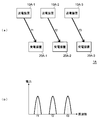
- FIG. 2 is a diagram illustrating the power transmission / reception system according to the first embodiment.
- FIG. 2A is a block diagram conceptually showing the power transmission / reception system of the first embodiment, and corresponds to FIG. 9 showing the conventional example.
- FIG. 2B is a graph showing the frequency of the magnetic field that is changed by each power transmission device of FIG. 2A, where the horizontal axis indicates the frequency and the vertical axis indicates the magnitude of the transmitted power.
- the power transmission device 10A-1 is set to transmit power to the power reception device 20A-1, and the power transmission device 10A-2 transmits power to the power reception device 20A-2.
- the power transmission device 10A-3 is set to transmit power to the power reception device 20A-3.
- the power transmission device 10A-2 is disposed between the power transmission device 10A-1 and the power transmission device 10A-3, and is adjacent to each of the power transmission device 10A-1 and the power transmission device 10A-3.
- the power receiving device 20A-2 is disposed between the power receiving device 20A-1 and the power receiving device 20A-3, and is adjacent to each of the power receiving device 20A-1 and the power receiving device 20A-3.
- the power transmission devices 10A-1 to 10A-3 transmit power to each of the power receiving devices 20A-1 to 20A-3 that are set to transmit power. Is indicated by a solid line.
- the center frequency f1 of the magnetic field changed by the power transmission device 10A-1, the center frequency f2 of the magnetic field changed by the power transmission device 10A-2, and the power transmission device 10A-3 The center frequency f3 of the magnetic field to be varied is different from each other.
- the power receiving device 20A-1 is configured to receive power in resonance with the variation in the magnetic field at the center frequency f1, and the power receiving device 20A-2 receives power in resonance with the variation in the magnetic field at the center frequency f2.
- the power receiving device 20A-3 is configured to be able to receive power in resonance with the fluctuation of the magnetic field at the center frequency f3.
- the frequencies at which the adjacent power transmission devices 10A-1 to 10A-3 fluctuate the magnetic field are different. Therefore, it is possible to suppress interference caused by the adjacent power transmission devices 10A-1 to 10A-3. Further, since the adjacent power transmission devices 10A-1 to 10A-3 can tolerate overlapping of power transmission timing, a plurality of power transmission devices 10A-1 to 10A-3 and power reception devices 20A-1 to 20A-3 are allowed. Can simultaneously transmit and receive power, and can easily manage the timing of transmitting and receiving power.
- a power transmission device that transmits and receives power and The number of power receiving device groups may be increased or decreased.
- the frequency at which the magnetic field fluctuates when each set transmits and receives power can be easily set by allocating frequencies that can be used. The same applies to the case where the number of sets increases or decreases while any of the power transmission devices and power reception devices transmit and receive power, and the frequency at which the magnetic field fluctuates when each pair transmits and receives power is Can be set easily.
- power may be transmitted by changing the magnetic field at substantially the same frequency.
- the frequencies at which the adjacent power transmission devices 10A-1 to 10A-3 change the magnetic field may be fixed in advance with different magnitudes.
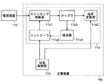
- FIG. 3 is a block diagram illustrating a configuration example 1 of the power transmission device provided in the power transmission and reception system according to the first embodiment. As shown in FIG.
- the power transmission device 10 a generates a magnetic field by passing a switching oscillator 11 a 1 that oscillates by switching permission / inhibition of conduction of a current supplied from the power supply device 10 and a current output from the switching oscillator 11 a 1.
- the magnetic field fluctuation unit 11a2 that fluctuates, the coupler 11a3 that branches and outputs part of the current that is output from the switching oscillator 11a1 and that is input to the magnetic field fluctuation unit 11a2, and the state of the current that is branched and output by the coupler 11a3
- the power transmission unit 11a includes a detector 11a4 to detect, and a controller 11a5 that controls the timing at which the switching oscillator 11a1 switches permission / inhibition of conduction based on the state of the current detected by the detector 11a4.
- the power transmission device 10a includes a power transmission control unit 12a that controls the controller 11a5 and the magnetic field variation unit 11a2.
- the magnetic field fluctuation unit 11a2 is composed of, for example, a reactance element (for example, a capacitor) and an inductance element (for example, a coil) connected in series. At least one of the reactance of the reactance element and the inductance of the inductance element is variable.
- the reactance element may be a varactor diode.
- the inductance element may be a plurality of coils that can switch the connection with the reactance element and have different inductances.
- the controller 11a5 Based on the state of the current detected by the detector 11a4, the controller 11a5 adjusts the timing at which the switching oscillator 11a1 switches whether to permit conduction, so that the current passed to the magnetic field fluctuation unit 11a2 is stabilized in a desired oscillation state. To control.
- the power transmission control unit 12a adjusts each of the reactance and the inductance of the magnetic field variation unit 11a2 and the timing at which the switching oscillator 11a1 controlled by the controller 11a5 switches permission / inhibition of conduction, so that the magnetic field variation unit 11a2
- the frequency of the changing magnetic field can be set to an arbitrary magnitude.
- the power transmission control unit 12a sets the frequency of the magnetic field changed by the power transmission unit 11a of the power transmission device 10a to be different from the frequency of the magnetic field changed by the power transmission unit of another nearby power transmission device.
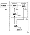
- FIG. 4 is a block diagram illustrating a configuration example 2 of the power transmission device provided in the power transmission and reception system according to the first embodiment. As shown in FIG.
- the power transmission device 10b oscillates the local oscillator 11b1 that outputs an oscillation signal that oscillates at a predetermined frequency, and the current supplied from the power supply device 110 based on the oscillation signal that is output from the local oscillator 11b1.
- the power transmission unit 11b includes the oscillation unit 11b2 to be changed and the magnetic field variation unit 11b3 that varies the magnetic field by passing the current output from the oscillation unit 11b2.
- the power transmission device 10b includes a power transmission control unit 12b that controls the local oscillator 11b1 and the magnetic field variation unit 11b3.
- variation part 11b3 is the structure similar to the magnetic field fluctuation
- the oscillating unit 11b2 oscillates the current passing through the magnetic field varying unit 11b3, for example, by mixing the oscillation signal output from the local oscillator 11b1 with the current supplied from the power supply device 110.
- the power transmission control unit 12b adjusts at least one of the reactance and inductance of the magnetic field variation unit 11b3 and the frequency of the oscillation signal output from the local oscillator 11b1, thereby adjusting the frequency of the magnetic field that the magnetic field variation unit 11b3 varies. It can be set to any size. Thereby, the power transmission control unit 12b sets the frequency of the magnetic field changed by the power transmission unit 11b of the power transmission device 10b to be different from the frequency of the magnetic field changed by the power transmission unit of another nearby power transmission device.
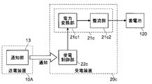
- FIG. 5 is a block diagram illustrating a configuration example 1 of the power receiving device provided in the power transmission and reception system according to the first embodiment. As illustrated in FIG.
- the power receiving device 20 c obtains a DC current that can charge the storage battery 120 by rectifying the current obtained by the conversion of the power conversion unit 21 c 1 and the conversion of the power conversion unit 21 c 1.
- the power receiving device 20c includes a power reception control unit 22c that controls the power conversion unit 21c1.
- the power conversion unit 21c1 includes, for example, a reactance element (for example, a capacitor) and an inductance element (for example, a coil) connected in series. At least one of the reactance of the reactance element and the inductance of the inductance element is variable.
- the reactance element may be a varactor diode.
- the inductance element may be a plurality of coils that can switch the connection with the reactance element and have different inductances.
- the power reception control unit 22c adjusts at least one of the reactance and the inductance of the power conversion unit 21c1, thereby resonating magnetic field fluctuation frequency (frequency of magnetic field fluctuation that can be efficiently converted into electric power. Can be set to any size.
- the power transmission device 10A includes the notification unit 13 that notifies the power reception device 20c set to transmit power of the frequency of the magnetic field that is changed by the power transmission unit of the power transmission device 10A.
- the power reception control unit 22c sets the resonance frequency of the power conversion unit 21c1 based on the frequency of the magnetic field, which is notified from the notification unit 13 and varies by the power transmission unit of the power transmission device 10A.
- the frequency of the magnetic field, which is notified from the notification unit 13 and is changed by the power transmission unit of the power transmission device 10A is set as it is as the resonance frequency of the power conversion unit 21c1.
- FIG. 6 is a block diagram illustrating a configuration example 2 of the power receiving device provided in the power transmission and reception system according to the first embodiment. As illustrated in FIG.
- the power receiving device 20d obtains a DC current that can charge the storage battery 120 by rectifying the current obtained by the conversion of the power conversion unit 21d1 and the conversion of the power conversion unit 21d1 by converting the fluctuation of the magnetic field into electric power.
- the power receiving device 20d includes a power reception control unit 22d that controls the power conversion unit 21d1.
- the power conversion unit 21d1 and the rectification unit 21d2 have the same configuration as the power conversion unit 21c1 and the rectification unit 21c2 (see FIG. 5) described in the configuration example 1 of the power receiving device.
- the power reception control unit 22d sequentially changes the resonance frequency of the power conversion unit 21d1, and sets the resonance frequency of the power conversion unit 21d1 by checking the power output from the rectification unit 21d2.
- the power reception control unit 22d preferentially sets a resonance frequency at which the power output from the rectification unit 21d2 is increased.
- the power reception control unit 22d sets a resonance frequency that realizes a state in which the charging efficiency of the power storage unit 120 is 80% or more.
- the power receiving apparatus 20d It becomes possible to receive power efficiently. Moreover, it becomes possible to simplify the structure of the power transmission apparatus and the power receiving apparatus 20d.
- FIG. 7 is a diagram illustrating a power transmission / reception system according to the second embodiment.
- FIG. 7A is a block diagram conceptually showing the power transmission / reception system of the second embodiment, and corresponds to FIG. 2A shown for the first embodiment.
- FIG. 7B is a graph showing the timing at which each power transmission device of FIG. 7A fluctuates the magnetic field, with the horizontal axis indicating time and the vertical axis indicating the magnitude of transmitted power.
- the power transmission device 10B-1 is set to transmit power to the power reception device 20B-1, and the power transmission device 10B-2 transmits power to the power reception device 20B-2. It is assumed that the power transmission device 10B-3 is set to transmit power to the power reception device 20B-3.
- the power transmission device 10B-2 is disposed between the power transmission device 10B-1 and the power transmission device 10B-3, and is adjacent to each of the power transmission device 10B-1 and the power transmission device 10B-3.
- the power receiving device 20B-2 is disposed between the power receiving device 20B-1 and the power receiving device 20B-3, and is adjacent to each of the power receiving device 20B-1 and the power receiving device 20B-3.
- FIG. 7A shows a state of the power transmission / reception system 1B at the timing t1 when the power transmission device 10B-1 transmits power to the power reception device 20B-1, and at this timing t1, the power transmission device 10B-1 receives the power reception device.
- a route for transmitting power to 20B-1 is shown by a solid line.
- each of the power transmission devices 10B-2 and 10B-3 supplies power to each of the power receiving devices 20B-2 and 20B-3 set to transmit power.
- a power transmission path is indicated by a broken line.
- the timing t1 when the power transmission device 10B-1 changes the magnetic field the timing t2 when the power transmission device 10B-2 changes the magnetic field
- the power transmission device 10B-3 change the magnetic field.
- the changing timing t3 is different.
- the power receiving devices 20B-1 to 20B-3 are configured to receive power by resonating with the frequency of the magnetic field changed by the power transmitting devices 10B-1 to 10B-3.
- the timings at which the adjacent power transmission devices 10B-1 to 10B-3 change the magnetic field are different. Therefore, it is possible to suppress interference caused by the adjacent power transmission devices 10B-1 to 10B-3. Further, since the frequencies of the magnetic fields fluctuated by the adjacent power transmission devices 10B-1 to 10B-3 can be made substantially equal, the configurations of the power reception devices 20B-1 to 20B-3 are made common and simplified (for example, substantially Equal fixed resonance frequencies).
- a power transmission device that transmits and receives power and The number of power receiving device groups may be increased or decreased.
- the timing at which each pair transmits and receives power can be easily set only by dividing the time by the number of sets. The same applies to the case where the number of sets increases or decreases while any of the power transmission devices and power reception devices are transmitting and receiving power, and it is easy to set the timing at which each pair transmits and receives power. Can be redone.
- the graph shown in FIG. 7B shows a case where the timings t1 to t3 are equal in proportion, but the proportion of any timing is increased (for example, the number of times is increased or the time per time is increased). You can make it longer). Further, the timings t1 to t3 are repeated in the order of t1, t2, and t3. However, the order of the timings t1 to t3 may be changed when repeating.
- the power transmitted at the respective timings t1 to t3 is substantially equal, but may be different or varied.
- the amount of power to be transmitted may be determined according to the amount of power charged in the storage battery 120. For example, the amount of power to be transmitted may be increased as the amount of power charged in the storage battery 120 is smaller. Further, as the number of sets of power transmission devices and power reception devices that transmit and receive power increases (the ratio of each timing per unit time decreases), the power transmitted by each power transmission device increases. I do not care.
- power may be transmitted at substantially the same timing.
- the timing at which the adjacent power transmission devices 10B-1 to 10B-3 change the magnetic field may be fixed as different timings in advance.
- FIG. 8 is a block diagram illustrating a configuration example of a power transmission device provided in the power transmission and reception system according to the second embodiment.
- each of the plurality of power transmission devices 10e-1 to 10e-3 includes power transmission units 11e-1 to 11e-3 and power transmission control units 12e-1 to 12e-3.
- the power transmission control units 12e-1 to 12e-3 can communicate with at least the power transmission control unit of another nearby power transmission device.
- the power transmission devices 10e-1 to 10e-3 in FIG. 8 are arranged in the same manner as the power transmission devices 10B-1 to 10B-3 in FIG. Specifically, the power transmission device 10e-1 corresponds to the power transmission device 10B-1, the power transmission device 10e-2 corresponds to the power transmission device 10B-2, and the power transmission device 10e-3 corresponds to the power transmission device 10B-3.
- the power transmission device 10e-1 corresponds to the power transmission device 10B-1
- the power transmission device 10e-2 corresponds to the power transmission device 10B-2
- the power transmission device 10e-3 corresponds to the power transmission device 10B-3.
- the power transmission control units 12e-1 to 12e-3 set the timing at which the power transmission units 11e-1 to 11e-3 transmit power by communicating with the power transmission control unit of the adjacent power transmission device (in this example, adjacent). .
- the timings at which the power transmission units 11e-1 to 11e-3 of the neighboring power transmission devices 10e-1 to 10e-3 change the magnetic field are set to be different.
- the power transmission units 11e-1 to 11e-3 are, for example, the power transmission unit 11a (see FIG. 3) provided in the power transmission device 10a of the configuration example 1 described in the first embodiment and the power transmission provided in the power transmission device 10b of the configuration example 2. It can be set as the structure similar to the part 11b (refer FIG. 4). However, in this embodiment, the frequency of the magnetic field changed by the power transmission units 11e-1 to 11e-3 can be fixed and not controlled by the power transmission control units 12e-1 to 12e-3.
- the power receiving unit of the power receiving device is, for example, a power receiving unit 21c (see FIG. 5) provided in the power receiving device 20c of the configuration example 1 described in the first embodiment, or a power receiving unit 21d provided in the power receiving device 20d of the configuration example 2.
- the configuration can be the same as (see FIG. 6).
- the resonance frequency of the power reception unit can be fixed and not controlled by the power reception control unit, and can be configured without the power reception control unit.
- the power transmission control units 12e-1 to 12e-3 included in the power transmission devices 10e-1 to 10e-3 communicate with each other to autonomously set the timing for transmitting power.
- a control unit common to the plurality of power transmission devices 10e-1 to 10e-3 is provided, and the control unit includes power transmission control units 12e-1 to 12e- of the respective power transmission devices 10e-1 to 10e-3. 3 may be configured so as to centrally set the timing of power transmission by communicating with each other.
- ⁇ Modification
- the first embodiment and the second embodiment described above can be implemented in combination. For example, a plurality of neighboring power transmission devices may transmit power at different timings with different magnetic field frequencies to be varied. Even if comprised in this way, it becomes possible to suppress the interference by the power transmission apparatus which adjoins.
- the power transmission / reception system 1, 1A, 1B has been described as being provided in the charging system 100 for charging a storage battery such as an electric vehicle, the power transmission / reception system 1, 1A, 1B is electrically driven.
- the present invention can also be applied to a storage battery charging system provided in an electronic device other than a vehicle, a power supply system that supplies power consumed by the electronic device, and the like.
- a control device such as a microcomputer.
- all or part of the functions realized by such a control device is described as a program, and the program is executed on a program execution device (for example, a computer) to realize all or part of the functions. It doesn't matter if you do.
- the power transmission / reception system 1, 1A, 1B shown in FIGS. 1, 2, and 7 is not limited to the above-described case, and can be realized by hardware or a combination of hardware and software. Further, when a part of the power transmission / reception system is configured using software, a block for a part realized by software represents a functional block of the part.
- the present invention can be used for a power transmission device that transmits power and a power transmission / reception system that includes the power transmission device and transmits and receives power in a contactless manner.
- a power transmission device that transmits power
- a power transmission / reception system that includes the power transmission device and transmits and receives power in a contactless manner.
Landscapes
- Engineering & Computer Science (AREA)
- Power Engineering (AREA)
- Computer Networks & Wireless Communication (AREA)
- Transportation (AREA)
- Mechanical Engineering (AREA)
- Signal Processing (AREA)
- Charge And Discharge Circuits For Batteries Or The Like (AREA)
Abstract
近接する送電装置による干渉を抑制する送電装置と、当該送電装置を備えた送受電システムであり、送電装置10は、電界及び磁界の少なくとも一方を変動させることで電力を送電する送電部11を備える。送電部11は、近接する他の送電装置とは異なる変動方法で、電界及び磁界の少なくとも一方を変動させる。例えば、送電部11が磁界を変動させる周波数が、近接する他の送電装置10が磁界を変動させる周波数と異なるようにする、あるいは、送電部11が磁界を変動させるタイミングが、近接する他の送電装置10が磁界を変動させるタイミングと異なるようにする。
Description
本発明は、電力を送電する送電装置や、当該送電装置を備え非接触で電力を送電及び受電する送受電システムに関する。
近年、蓄電池の大容量化が進み、電動車両(例えば、電動自動車や電動バイク、電動自転車など)の駆動用としても利用されるようになってきている。電動車両は、走行するために蓄電池の充電が必要であり、当該充電は、ユーザの自宅だけでなく、駐車場や駐輪場、充電スタンドなどの自宅以外の施設でも行われ得る。
従来、電動車両を充電する場合、電力を供給する装置と電動車両とを接触させる(例えば、ケーブルなどで接続する)必要や、電動車両から蓄電池を取り外す必要などがあった。しかし、このような作業は、多大な時間や労力が必要となるため、好ましくない。そこで、電動車両に備えられる蓄電池を、非接触で充電する(無接点充電を行う)充電システムが提案されている。
例えば、特許文献1では、送電装置が地中に配置され、当該送電装置が地上の電動車両の受電装置に対して電力を送電する充電システムが提案されている。また、特許文献2では、道路に設けられている電光掲示板などに送電装置が配置され、当該送電装置が道路上の電動車両の受電装置に対して電力を送電する充電システムが提案されている。
例えば、駐車場や駐輪場などに無接点充電を行う送電装置を配置する場合、送電装置を近接して配置せざるを得ないことがある。このような場合、近接するそれぞれの送電装置が同時に電力を送電すると、互いに干渉して効率よく充電することができなくなるため、
問題となる。
問題となる。
この問題について、図面を参照して説明する。図9は、従来の充電システムに備えられる送受電システムを概念的に示すブロック図である。図9に示す送受電システムTRxでは、送電装置Tx1が、電動車両の受電装置Rx1に電力を送電するように設定され、送電装置Tx2が、電動車両の受電装置Rx2に電力を送電するように設定され、送電装置Tx3が、電動車両の受電装置Rx3に電力を送電するように設定されている。また、送電装置Tx2は、送電装置Tx1及び送電装置Tx3の間に配置され、送電装置Tx1及び送電装置Tx3のそれぞれに隣接する。受電装置Rx2も同様に、受電装置Rx1及び受電装置Rx3の間に配置され、受電装置Rx1及び受電装置Rx3のそれぞれに隣接する。また、図9では、送電装置Tx1~Tx3のそれぞれが、電力を送電するように設定された受電装置Rx1~Rx3のそれぞれに対して電力を送電する経路を、太線で示している。さらに、送電装置Tx2が受電装置Rx2に電力を送電する際に、他の送電装置Tx1,Tx3や電力を送電するように設定されていない受電装置Rx1,Rx3へ与える影響(干渉)を、細線で示している。
送電装置Tx2は、電界や磁界などを変動させることで、電力を送電するように設定されている受電装置Rx2に対して電力を送電する。このとき、送電装置Tx2による電界や磁界の変動は、電力を送電するように設定されていない受電装置Rx1にも少なからず伝播する。すると、受電装置Rx1において、送電装置Tx1による電界や磁界の変動に送電装置Tx2による電界や磁界の変動が干渉し、場合によっては(例えば、それぞれの変動が逆相になると)受電装置Rx1が受電する電力が減少する。さらに、送電装置Tx2,Tx3と受電装置Rx3との間においても、同様の事態が生じ得る。
また、送電装置Tx2による電界や磁界の変動は、送電装置Tx1にも伝播する。すると、送電装置Tx2から送電装置Tx1に対して電力が送電されてしまい、結果として受電装置Rx2が受電する電力が減少する。さらに、送電装置Tx2,Tx3と受電装置Rx2との間においても、同様の事態が生じ得る。
上述のように、受電装置Rx1~Rx3が受電する電力が減少すると、期待した電力量を蓄電池に充電することが困難になったり、充電に要する時間が長くなったりするため、問題となる。また、送電する電力が無駄に消費され、充電効率が悪化するため、問題となる。
そこで本発明は、近接する送電装置による干渉を抑制する送電装置と、当該送電装置を備えた送受電システムを提供することを目的とする。
上記目的を達成するために、本発明における送電装置は、電界及び磁界の少なくとも一方を変動させることで電力を送電する送電部を備え、前記送電部が、近接する他の送電装置とは異なる変動方法で、電界及び磁界の少なくとも一方を変動させることを特徴とする。
また、上記構成の送電装置において、前記送電部が、磁界を変動させることで電力を送電するものであり、前記送電部が磁界を変動させる周波数が、近接する他の送電装置が磁界を変動させる周波数と異なることとしても構わない。
このように構成すると、近接する送電装置が電力を送電するタイミングの重複を許容することができるため、複数の送電装置及び受電装置が同時に電力を送電及び受電することが可能になるとともに、電力を送電及び受電するタイミングの管理を容易にすることが可能になる。
また、上記構成の送電装置において、前記送電部が、磁界を変動させることで電力を送電するものであり、前記送電部が磁界を変動させるタイミングが、近接する他の送電装置が磁界を変動させるタイミングと異なることとしても構わない。
このように構成すると、近接する送電装置が変動させる磁界の周波数を略等しくすることができるため、受電装置の構成を共通化及び簡略化することが可能になる。
また、上記構成の送電装置において、前記送電部の変動方法を制御する送電制御部をさらに備え、前記送電制御部が、近接する他の送電装置とは異なる変動方法を設定し、前記送電部が当該変動方法で電界及び磁界の少なくとも一方を変動させても構わない。
このように構成すると、送電装置の設置の自由度を向上させることが可能になる。また、送電部の変動方法を、状況に応じて変更することが可能になる。
また、本発明の送受電システムは、上記の送電装置と、前記送電装置から送電された電力を受電する受電装置と、を備え、前記受電装置が、前記送電部による電界及び磁界の少なくとも一方の変動を、前記送電部の変動方法に対応した変換方法で電力に変換する受電部を備えることを特徴とする。
また、本発明の送受電システムは、上記の送電装置と、前記送電装置から送電された電力を受電する受電装置と、を備え、前記送電装置が、前記送電部の変動方法を前記受電装置に通知する通知部をさらに備え、前記受電装置が、前記送電部による電界及び磁界の少なくとも一方の変動を電力に変換する受電部と、前記受電部の変換方法を設定する受電制御部と、を備え、前記受電制御部が、前記通知部から通知される前記送電部の変動方法に対応した変換方法を設定することを特徴とする。
このように構成すると、送電部の変動方法が様々な状態を取り得るものであったとしても、受電装置が効率良く電力を受電することが可能になる。また、送電部による電界及び磁界の少なくとも一方の変動を効率よく電力に変換することができる受電部の変換方法を、受電制御部が容易に設定することが可能になる。
また、上記構成の送受電システムにおいて、前記送電部が、磁界を変動させることで電力を送電するとともに、前記送電部が磁界を変動させる周波数が、近接する他の送電装置が磁界を変動させる周波数と異なるものであり、前記受電制御部が、前記通知部から通知される、前記送電部が変動させる磁界の周波数に基づいて、前記受電部が共鳴する磁界の変動の周波数を設定することとしても構わない。
また、本発明の送受電システムは、上記の送電装置と、前記送電装置から送電された電力を受電する受電装置と、を備え、前記受電装置が、前記送電部による電界及び磁界の少なくとも一方の変動を電力に変換する受電部と、前記受電部の変換方法を設定する受電制御部と、を備え、前記受電制御部が、前記受電部の変換方法を順次変更し、受電する電力が大きい変換方法を優先的に設定することを特徴とする。
このように構成すると、送電部の変動方法が様々な状態を取り得るものであったとしても、受電装置が効率良く電力を受電することが可能になる。また、送電装置及び受電装置の構成を簡略化することが可能になる。
また、上記構成の送受電システムにおいて、前記送電部が、磁界を変動させることで電力を送電するとともに、前記送電部が磁界を変動させる周波数が、近接する他の送電装置が磁界を変動させる周波数と異なるものであり、前記受電制御部が、前記受電部が共鳴する磁界の変動の周波数を順次変更し、受電する電力が大きい前記受電部が共鳴する磁界の変動の周波数を優先的に設定することを特徴とする。
また、本発明の充電システムは、電力を供給する電源装置と、前記電源装置から供給される電力を送電する上記の送電装置と、前記送電装置から送電される電力を受電する受電装置と、前記受電装置が受電した電力が充電される蓄電池と、を備え、前記受電装置が、前記送電部による電界及び磁界の少なくとも一方の変動を、前記送電部の変動方法に対応した変換方法で電力に変換する受電部を備えることを特徴とする。
本発明の構成とすると、近接する送電装置の送電部による、電界及び磁界の少なくとも一方の変動方法が、異なるものとなる。そのため、近接する送電装置による干渉を抑制することが可能になる。
本発明の意義ないし効果は、以下に示す実施の形態の説明によりさらに明らかとなろう。ただし、以下の実施の形態は、あくまでも本発明の実施の形態の一つであって、本発明ないし各構成要件の用語の意義は、以下の実施の形態に記載されたものに制限されるものではない。
<<送受電システム>>
<概略構成>
まず、本発明の実施の一形態である送受電システムの概略構成の一例について、図面を参照して説明する。なお、送受電システムの説明の具体化のため、電動車両などの蓄電池を無接点充電する充電システムに、本発明の実施の一形態である送受電システムが備えられる場合を例示する。
<概略構成>
まず、本発明の実施の一形態である送受電システムの概略構成の一例について、図面を参照して説明する。なお、送受電システムの説明の具体化のため、電動車両などの蓄電池を無接点充電する充電システムに、本発明の実施の一形態である送受電システムが備えられる場合を例示する。
図1は、本発明の実施の一形態である送受電システムを備えた充電システムの概略構成例を示すブロック図である。図1に示す充電システム100は、電力を供給する電源装置110と、電源装置110から供給される電力を送電する送電装置10と、送電装置10から送電された電力を受電する受電装置20と、受電装置20で受電された電力が充電される蓄電池120と、を備える。送受電システム1は、送電装置10と受電装置20とを備える。受電装置20及び蓄電池120は、例えば電動車両などに備えられる。
送電装置10は、外部(電源装置110)から供給される電力を用いて電界及び磁界の少なくとも一方を変動させることで電力を送電する送電部11と、送電部11による変動方法を制御する送電制御部12と、を備える。受電装置20は、送電部11による電界及び磁界の少なくとも一方の変動を電力に変換して外部(蓄電池120)に供給する受電部21と、受電部21の変換方法を制御する受電制御部22と、を備える。
充電システム100には、複数の送電装置10が備えられる。また、受電装置20も、充電システム100内に複数備えられ得る。そして、送電装置10と、当該送電装置10が電力を送電するように設定される受電装置20と、から成る組が複数成立し、同時期に電力を送受及び受電する場合が生じ得る。具体的に例えば、駐車場のそれぞれの駐車スペースに送電装置10が配置される場合であり、受電装置20を備える複数の電動車両がそれぞれの駐車スペースに駐車され、それぞれの電動車両のユーザが、それぞれの駐車スペースに配置された送電装置10に対して同時期に充電指示を与える場合などである。このような場合、上述のような、近接する送電装置10による干渉が懸念される。
そこで、本例の送受電システム1では、近接する(例えば、上述の干渉を生じる程度に近接する。以下同じ。)送電装置10が同時期に電力を送電する際に、これらの送電装置10に備えられるそれぞれの送電部11が、異なる変動方法で電界及び磁界の少なくとも一方を変動させることとする。このとき、送電制御部12が、近接する送電装置10の送電部11の変動方法が異なるように、それぞれの送電部11の変動方法を設定する。なお、近接する送電装置10が、予め送電部11の変動方法が異なるように構成されている場合などでは、送電制御部12を備えない構成としても構わない。
また、受電装置20の受電部21は、送電装置10の送電部11による電界及び磁界の少なくとも一方の変動を、電力に変換する。このとき、受電制御部22は、受電装置20と組を成す送電装置10の送電部11の変動方法に対応した変換方法を、受電部21の変換方法として設定する。なお、送電部11の変動方法が異なる場合でも、同じ変換方法で電力を受電することが可能であれば、受電制御部22を備えない構成としても構わない。
以上のように構成すると、近接する送電装置10の送電部11による、電界及び磁界の少なくとも一方の変動方法が、異なるものとなる。そのため、近接する送電装置10による干渉を抑制することが可能になる。
また、送電装置10に送電制御部12を備える構成として、送電部11の変動方法を事後的に変更可能な構成とすると、送電装置10の設置の自由度を向上させることが可能になる。また、送電部11の変動方法を、状況に応じて変更することが可能になる。
なお、送電部11及び受電部21は、電界及び磁界の少なくとも一方の変動により電力を送電及び受電するものであれば、どのような方法で電力を送電及び受電しても構わない。例えば、磁束の変動により電力を送電及び受電する方法や、磁界または電界の変動の共鳴により電力を送電及び受電する方法、電磁波を送信及び受信(光の発光及び受光も含む)することで電力を送電及び受電する方法などで、電力を送電及び受電しても構わない。
ただし、以下の各実施例では、説明の具体化のため、送電部11及び受電部21が、磁界の変動の共鳴により電力を送電及び受電する場合を例示する。
ただし、以下の各実施例では、説明の具体化のため、送電部11及び受電部21が、磁界の変動の共鳴により電力を送電及び受電する場合を例示する。
また、電源装置110は、太陽電池や商用電源など、どのような電源であっても構わない。ただし、以下の各実施例では、説明の具体化のため、電源装置110が直流電力を供給可能な電源である場合を例示する。
<第1実施例>
次に、送受電システムの第1実施例について、図面を参照して説明する。図2は、第1実施例の送受電システムを示す図である。図2(a)は、第1実施例の送受電システムを概念的に示すブロック図であり、従来例について示した図9に相当するものである。図2(b)は、図2(a)の各送電装置が変動させる磁界の周波数を示すグラフであり、横軸が周波数、縦軸が送電される電力の大きさを示すものである。
<第1実施例>
次に、送受電システムの第1実施例について、図面を参照して説明する。図2は、第1実施例の送受電システムを示す図である。図2(a)は、第1実施例の送受電システムを概念的に示すブロック図であり、従来例について示した図9に相当するものである。図2(b)は、図2(a)の各送電装置が変動させる磁界の周波数を示すグラフであり、横軸が周波数、縦軸が送電される電力の大きさを示すものである。
図2に示す送受電システム1Aでは、送電装置10A-1が、受電装置20A-1に電力を送電するように設定され、送電装置10A-2が、受電装置20A-2に電力を送電するように設定され、送電装置10A-3が、受電装置20A-3に電力を送電するように設定されている。また、送電装置10A-2は、送電装置10A-1及び送電装置10A-3の間に配置され、送電装置10A-1及び送電装置10A-3のそれぞれに隣接する。受電装置20A-2も同様に、受電装置20A-1及び受電装置20A-3の間に配置され、受電装置20A-1及び受電装置20A-3のそれぞれに隣接する。また、図2(a)では、送電装置10A-1~10A-3のそれぞれが、電力を送電するように設定された受電装置20A-1~20A-3のそれぞれに対して電力を送電する経路を、実線で示している。
図2(a),(b)に示すように、送電装置10A-1が変動させる磁界の中心周波数f1と、送電装置10A-2が変動させる磁界の中心周波数f2と、送電装置10A-3が変動させる磁界の中心周波数f3と、はそれぞれ異なる。また、受電装置20A-1は、中心周波数f1の磁界の変動と共鳴して電力を受電可能な構成であり、受電装置20A-2は、中心周波数f2の磁界の変動と共鳴して電力を受電可能な構成であり、受電装置20A-3は、中心周波数f3の磁界の変動と共鳴して電力を受電可能な構成である。
以上のように構成すると、近接する送電装置10A-1~10A-3が磁界を変動させる周波数が異なるものとなる。そのため、近接する送電装置10A-1~10A-3による干渉を抑制することが可能になる。また、近接する送電装置10A-1~10A-3が電力を送電するタイミングの重複を許容することができるため、複数の送電装置10A-1~10A-3及び受電装置20A-1~20A-3が同時に電力を送電及び受電することが可能になるとともに、電力を送電及び受電するタイミングの管理を容易にすることが可能になる。
なお、3つの送電装置10A-1~10A-3及び3つの受電装置20A-1~20A-3が電力を送電及び受電する送受電システム1Aについて説明したが、電力を送電及び受電する送電装置及び受電装置の組の数がこれより増えても減っても構わない。本実施例では、それぞれの組が電力を送電及び受電する際に磁界を変動する周波数を、使用可能な周波数の中から割り当てることで容易に設定することができる。いずれかの送電装置及び受電装置が電力を送電及び受電している途中で、組の数が増減する場合も同様であり、それぞれの組が電力を送電及び受電する際に磁界を変動する周波数は、容易に設定することができる。
また、干渉を生じ得ない程度に離間して配置されている送電装置については、略等しい周波数で磁界を変動させることで電力を送電しても構わない。また、近接するそれぞれの送電装置10A-1~10A-3が磁界を変動させる周波数を、予め異なる大きさとして固定しても構わない。
また、第1実施例の送受電システムに1Aに備えられる送電装置10A-1~10A-3及び受電装置20A-1~20A-3は、上述のように異なる周波数で変動させる磁界によって電力を送電及び受電するものであれば、どのような構成であっても構わない。それぞれの構成の具体例について、以下図面を参照して説明する。
[送電装置の構成例1]
図3は、第1実施例の送受電システムに備えられる送電装置の構成例1を示すブロック図である。図3に示すように、送電装置10aは、電源装置10から供給される電流の導通の許否を切り替えることで発振させるスイッチング発振器11a1と、スイッチング発振器11a1から出力される電流が通じられることで磁界を変動させる磁界変動部11a2と、スイッチング発振器11a1から出力されて磁界変動部11a2に入力される電流の一部を分岐させて出力するカップラ11a3と、カップラ11a3で分岐されて出力される電流の状態を検出する検波器11a4と、検波器11a4で検出される電流の状態に基づいてスイッチング発振器11a1が導通の許否を切り替えるタイミングを制御するコントローラ11a5と、を備える送電部11aを備える。また、送電装置10aは、コントローラ11a5及び磁界変動部11a2を制御する送電制御部12aを備える。
磁界変動部11a2は、例えば、直列接続されるリアクタンス素子(例えば、コンデンサ)とインダクタンス素子(例えば、コイル)とから成る。リアクタンス素子のリアクタンス及びインダクタンス素子のインダクタンスの少なくとも一方は、可変である。例えば、リアクタンス素子が、バラクタダイオードであっても構わない。また例えば、インダクタンス素子が、リアクタンス素子との接続が切替可能でありインダクタンスが異なる複数のコイルであっても構わない。
コントローラ11a5は、検波器11a4で検出される電流の状態に基づいて、スイッチング発振器11a1が導通の許否を切り替えるタイミングを調整することで、磁界変動部11a2に通じられる電流が所望の発振状態で安定するように制御する。
送電制御部12aは、磁界変動部11a2のリアクタンス及びインダクタンスの少なくとも一方と、コントローラ11a5により制御されるスイッチング発振器11a1が導通の許否を切り替えるタイミングと、のそれぞれを調整することで、磁界変動部11a2が変動させる磁界の周波数を任意の大きさに設定することができる。これにより、送電制御部12aは、送電装置10aの送電部11aが変動させる磁界の周波数を、近接する他の送電装置の送電部が変動させる磁界の周波数とは異なる大きさにする。
なお、それぞれの送電装置の送電部が変動させる磁界の周波数は、例えば、それぞれの送電装置に備えられるそれぞれの送電制御部が互いに通信することで、自律的に設定するものであっても構わない。また例えば、複数の送電装置で共通する制御部を備え、当該制御部がそれぞれの送電装置の送電制御部とそれぞれ通信することで、一元的に設定するものであっても構わない。
[送電装置の構成例2]
図4は、第1実施例の送受電システムに備えられる送電装置の構成例2を示すブロック図である。図4に示すように、送電装置10bは、所定の周波数で発振する発振信号を出力する局部発振器11b1と、電源装置110から供給される電流を局部発振器11b1から出力される発振信号に基づいて発振させる発振部11b2と、発振部11b2から出力される電流が通じられることで磁界を変動させる磁界変動部11b3と、を備える送電部11bを備える。また、送電装置10bは、局部発振器11b1及び磁界変動部11b3を制御する送電制御部12bを備える。なお、磁界変動部11b3は、送電装置の構成例1で述べた磁界変動部11a2(図3参照)と同様の構成である。
発振部11b2は、例えば、局部発振器11b1から出力される発振信号を、電源装置110から供給される電流に混合することで、磁界変動部11b3に通じる電流を発振させる。
送電制御部12bは、磁界変動部11b3のリアクタンス及びインダクタンスの少なくとも一方と、局部発振器11b1が出力する発振信号の周波数と、のそれぞれを調整することで、磁界変動部11b3が変動させる磁界の周波数を任意の大きさに設定することができる。これにより、送電制御部12bは、送電装置10bの送電部11bが変動させる磁界の周波数を、近接する他の送電装置の送電部が変動させる磁界の周波数とは異なる大きさにする。
なお、それぞれの送電装置の送電部が変動させる磁界の周波数は、例えば、それぞれの送電装置に備えられるそれぞれの送電制御部が互いに通信することで、自律的に設定するものであっても構わない。また例えば、複数の送電装置で共通する制御部を備え、当該制御部がそれぞれの送電装置の送電制御部とそれぞれ通信することで、一元的に設定するものであっても構わない。
[受電装置の構成例1]
図5は、第1実施例の送受電システムに備えられる受電装置の構成例1を示すブロック図である。図5に示すように、受電装置20cは、磁界の変動を電力に変換する電力変換部21c1と、電力変換部21c1の変換により得られる電流を整流して蓄電池120に充電可能な直流電流を得る整流部21c2と、を備える受電部21cを備える。また、受電装置20cは、電力変換部21c1を制御する受電制御部22cを備える。
[受電装置の構成例1]
図5は、第1実施例の送受電システムに備えられる受電装置の構成例1を示すブロック図である。図5に示すように、受電装置20cは、磁界の変動を電力に変換する電力変換部21c1と、電力変換部21c1の変換により得られる電流を整流して蓄電池120に充電可能な直流電流を得る整流部21c2と、を備える受電部21cを備える。また、受電装置20cは、電力変換部21c1を制御する受電制御部22cを備える。
電力変換部21c1は、例えば、直列接続されるリアクタンス素子(例えば、コンデンサ)とインダクタンス素子(例えば、コイル)とから成る。リアクタンス素子のリアクタンス及びインダクタンス素子のインダクタンスの少なくとも一方は、可変である。例えば、リアクタンス素子が、バラクタダイオードであっても構わない。また例えば、インダクタンス素子が、リアクタンス素子との接続が切替可能でありインダクタンスが異なる複数のコイルであっても構わない。
受電制御部22cは、電力変換部21c1のリアクタンス及びインダクタンスの少なくとも一方を調整することで、共鳴する磁界の変動の周波数(効率よく電力に変換することができる磁界の変動の周波数。以下、共鳴周波数とする。)を、任意の大きさに設定することができる。
本構成例では、送電装置10Aが、電力を送電するように設定された受電装置20cに対して送電装置10Aの送電部が変動させる磁界の周波数を通知する通知部13を、備える。受電制御部22cは、通知部13から通知される、送電装置10Aの送電部が変動させる磁界の周波数に基づいて、電力変換部21c1の共鳴周波数を設定する。例えば、通知部13から通知される、送電装置10Aの送電部が変動させる磁界の周波数を、そのまま電力変換部21c1の共鳴周波数として設定する。
このように構成すると、送電部の変動方法(本実施例では、変動させる磁界の周波数)が様々な状態(本実施例では、異なる周波数)を取り得るものであったとしても、受電装置20cが効率良く電力を受電することが可能になる。また、送電部による電界及び磁界の少なくとも一方の変動(本実施例では、磁界の変動)を効率よく電力に変換することができる受電部11の変換方法(本実施例では、共鳴周波数)を、受電制御部22cが容易に設定することが可能になる。
[受電装置の構成例2]
図6は、第1実施例の送受電システムに備えられる受電装置の構成例2を示すブロック図である。図6に示すように、受電装置20dは、磁界の変動を電力に変換する電力変換部21d1と、電力変換部21d1の変換により得られる電流を整流して蓄電池120に充電可能な直流電流を得る整流部21d2と、を備える受電部21dを備える。また、受電装置20dは、電力変換部21d1を制御する受電制御部22dを備える。なお、電力変換部21d1及び整流部21d2は、受電装置の構成例1で述べた電力変換部21c1及び整流部21c2(図5参照)と同様の構成である。
[受電装置の構成例2]
図6は、第1実施例の送受電システムに備えられる受電装置の構成例2を示すブロック図である。図6に示すように、受電装置20dは、磁界の変動を電力に変換する電力変換部21d1と、電力変換部21d1の変換により得られる電流を整流して蓄電池120に充電可能な直流電流を得る整流部21d2と、を備える受電部21dを備える。また、受電装置20dは、電力変換部21d1を制御する受電制御部22dを備える。なお、電力変換部21d1及び整流部21d2は、受電装置の構成例1で述べた電力変換部21c1及び整流部21c2(図5参照)と同様の構成である。
本構成例では、受電制御部22dが、電力変換部21d1の共鳴周波数を順次変更するとともに、整流部21d2から出力される電力を確認することで、電力変換部21d1の共鳴周波数を設定する。例えば、受電制御部22dは、整流部21d2から出力される電力が大きくなる共鳴周波数を、優先的に設定する。具体的に例えば、受電制御部22dは、蓄電部120の充電効率が80%以上となる状態を実現する共鳴周波数を設定する。
このように構成すると、送電部の変動方法(本実施例では、変動させる磁界の周波数)が様々な状態(本実施例では、異なる周波数)を取り得るものであったとしても、受電装置20dが効率良く電力を受電することが可能になる。また、送電装置及び受電装置20dの構成を簡略化することが可能になる。
なお、本実施例の送受電システム1Aは、上述の送電装置の構成例1及び構成例2と、受電装置の構成例1及び構成例2と、の任意の組み合わせで実現することができる。
<第2実施例>
次に、送受電システム第2実施例について、図面を参照して説明する。図7は、第2実施例の送受電システムを示す図である。図7(a)は、第2実施例の送受電システムを概念的に示すブロック図であり、第1実施例について示した図2(a)に相当するものである。図7(b)は、図7(a)の各送電装置が磁界を変動させるタイミングを示すグラフであり、横軸が時間、縦軸が送電される電力の大きさを示すものである。
<第2実施例>
次に、送受電システム第2実施例について、図面を参照して説明する。図7は、第2実施例の送受電システムを示す図である。図7(a)は、第2実施例の送受電システムを概念的に示すブロック図であり、第1実施例について示した図2(a)に相当するものである。図7(b)は、図7(a)の各送電装置が磁界を変動させるタイミングを示すグラフであり、横軸が時間、縦軸が送電される電力の大きさを示すものである。
図7の送受電システム1Bでは、送電装置10B-1が、受電装置20B-1に電力を送電するように設定され、送電装置10B-2が、受電装置20B-2に電力を送電するように設定され、送電装置10B-3が、受電装置20B-3に電力を送電するように設定されているものとする。また、送電装置10B-2は、送電装置10B-1及び送電装置10B-3の間に配置され、送電装置10B-1及び送電装置10B-3のそれぞれに隣接する。受電装置20B-2も同様に、受電装置20B-1及び受電装置20B-3の間に配置され、受電装置20B-1及び受電装置20B-3のそれぞれに隣接する。
図7(a)は、送電装置10B-1が受電装置20B-1へ電力を送電するタイミングt1における送受電システム1Bの状態を示すものであり、このタイミングt1で送電装置10B-1が受電装置20B-1へ電力を送電する経路を実線で示している。さらに、タイミングt1と異なるタイミングt2,t3において、送電装置10B-2,10B-3のそれぞれが、電力を送電するように設定された受電装置20B-2,20B-3のそれぞれに対して電力を送電する経路を破線で示している。
図7(a),(b)に示すように、送電装置10B-1が磁界を変動させるタイミングt1と、送電装置10B-2が磁界を変動させるタイミングt2と、送電装置10B-3が磁界を変動させるタイミングt3と、はそれぞれ異なる。また、受電装置20B-1~20B-3は、送電装置10B-1~10B-3が変動させる磁界の周波数と共鳴して電力を受電可能な構成である。
以上のように構成すると、近接する送電装置10B-1~10B-3が磁界を変動させるタイミングが異なるものとなる。そのため、近接する送電装置10B-1~10B-3による干渉を抑制することが可能になる。また、近接する送電装置10B-1~10B-3が変動させる磁界の周波数を略等しくすることができるため、受電装置20B-1~20B-3の構成を共通化及び簡略化する(例えば、略等しい固定の共鳴周波数とする)ことが可能になる。
なお、3つの送電装置10B-1~10B-3及び3つの受電装置20B-1~20B-3が電力を送電及び受電する送受電システム1Bについて説明したが、電力を送電及び受電する送電装置及び受電装置の組の数がこれより増えても減っても構わない。本実施例では、組の数で時間を分割するだけで、それぞれの組が電力を送電及び受電するタイミングを容易に設定することができる。また、いずれかの送電装置及び受電装置が電力を送電及び受電している途中で、組の数が増減する場合も同様であり、それぞれの組が電力を送電及び受電するタイミングを、容易に設定し直すことができる。
また、図7(b)に示すグラフでは、タイミングt1~t3が等しい割合になる場合を示しているが、いずれかのタイミングの割合を大きく(例えば、回数を多くしたり、一回当たりの時間を長くしたり)しても構わない。また、タイミングt1~t3が、t1、t2、t3の順で繰り返すものとしているが、繰り返す際にタイミングt1~t3の順番を異ならせても構わない。
また、図7(b)に示すグラフでは、それぞれのタイミングt1~t3で送電される電力を略等しいものとしているが、異ならせても構わないし、変動させても構わない。具体的に、蓄電池120に充電されている電力量に応じて、送電する電力量を決定しても構わない。例えば、蓄電池120に充電されている電力量が小さいほど、送電する電力量を大きくしても構わない。また、電力を送電及び受電する送電装置及び受電装置の組の数が多くなるほど(単位時間当たりのそれぞれのタイミングの割合が小さくなるほど)、それぞれの組の送電装置が送電する電力を大きくしても構わない。
また、干渉を生じ得ない程度に離間して配置されている送電装置については、略等しいタイミングで電力を送電しても構わない。また、近接するそれぞれの送電装置10B-1~10B-3が磁界を変動させるタイミングを、予め異なるタイミングとして固定しても構わない。
また、第2実施例の送受電システムに1Bに備えられる送電装置10B-1~10B-3及び受電装置20B-1~20B-3は、上述のように異なるタイミングで電力を送電及び受電するものであれば、どのような構成であっても構わない。それぞれの構成の具体例について、以下図面を参照して説明する。
[送電装置及び受電装置の構成例]
図8は、第2実施例の送受電システムに備えられる送電装置の構成例を示すブロック図である。図8は、複数の送電装置10e-1~10e-3のそれぞれが、送電部11e-1~11e-3と、送電制御部12e-1~12e-3とを備える。ただし、本例では、送電制御部12e-1~12e-3が、少なくとも近接する他の送電装置の送電制御部と通信し得る。なお、図8の送電装置10e-1~10e-3は、図7の送電装置10B-1~10B-3と同様に配置されているものとする。具体的には、送電装置10e-1が送電装置10B-1に相当し、送電装置10e-2が送電装置10B-2に相当し、送電装置10e-3が送電装置10B-3に相当するものとする。
送電制御部12e-1~12e-3は、近接(本例では隣接)する送電装置の送電制御部と通信することで、送電部11e-1~11e-3が電力を送電するタイミングを設定する。このとき、上述のように、近接する送電装置10e-1~10e-3の送電部11e-1~11e-3が磁界を変動させるタイミングが、異なるように設定する。
送電部11e-1~11e-3は、例えば第1実施例で述べた構成例1の送電装置10aに備えられる送電部11a(図3参照)や、構成例2の送電装置10bに備えられる送電部11b(図4参照)と同様の構成とすることができる。ただし、本実施例では、送電部11e-1~11e-3が変動させる磁界の周波数を、送電制御部12e-1~12e-3によって制御されない固定のものとすることができる。
また、受電装置の受電部は、例えば第1実施例で述べた構成例1の受電装置20cに備えられる受電部21c(図5参照)や、構成例2の受電装置20dに備えられる受電部21d(図6参照)と同様の構成とすることができる。ただし、本実施例では、受電部の共鳴周波数を、受電制御部によって制御されない固定のものとすることが可能であり、受電制御部を備えない構成とすることも可能である。
なお、図8では、それぞれの送電装置10e-1~10e-3に備えられるそれぞれの送電制御部12e-1~12e-3が互いに通信することで、電力を送電するタイミングを自律的に設定する構成について示したが、複数の送電装置10e-1~10e-3で共通する制御部を備え、当該制御部がそれぞれの送電装置10e-1~10e-3の送電制御部12e-1~12e-3とそれぞれ通信することで、電力を送電するタイミングを一元的に設定するもの構成としても構わない。
<<変形例>>
なお、上述の第1実施例及び第2実施例は、組み合わせて実施することも可能である。例えば、近接する複数の送電装置が、変動させる磁界の周波数を異ならせ、かつ、異なるタイミングで電力を送電しても構わない。このように構成しても、近接する送電装置による干渉を抑制することが可能になる。
<<変形例>>
なお、上述の第1実施例及び第2実施例は、組み合わせて実施することも可能である。例えば、近接する複数の送電装置が、変動させる磁界の周波数を異ならせ、かつ、異なるタイミングで電力を送電しても構わない。このように構成しても、近接する送電装置による干渉を抑制することが可能になる。
本発明の実施の一形態である送受電システム1,1A,1Bを、電動車両などの蓄電池を充電する充電システム100に備えられるものとして説明したが、送受電システム1,1A,1Bは、電動車両以外の電子機器に備えられる蓄電池の充電システムや、電子機器で消費される電力の供給を行う電力供給システムなどにも適用可能である。
本発明の実施形態における送受電システム1,1A,1Bについて、送電装置10,10A-1~10A-3,10B-1~10B-3や受電装置20,20A-1~20A-3,20B-1~20B-3などの一部または全部の動作を、マイコンなどの制御装置が
行うこととしても構わない。さらに、このような制御装置によって実現される機能の全部または一部をプログラムとして記述し、該プログラムをプログラム実行装置(例えばコンピュータ)上で実行することによって、その機能の全部または一部を実現するようにしても構わない。
行うこととしても構わない。さらに、このような制御装置によって実現される機能の全部または一部をプログラムとして記述し、該プログラムをプログラム実行装置(例えばコンピュータ)上で実行することによって、その機能の全部または一部を実現するようにしても構わない。
また、上述した場合に限らず、図1、図2及び図7に示す送受電システム1,1A,1Bは、ハードウェア、或いは、ハードウェアとソフトウェアの組み合わせによって実現可能である。また、ソフトウェアを用いて送受電システムの一部を構成する場合、ソフトウェアによって実現される部位についてのブロックは、その部位の機能ブロックを表すこととする。
以上、本発明における実施形態について説明したが、本発明の範囲はこれに限定されるものではなく、発明の主旨を逸脱しない範囲で種々の変更を加えて実行することができる。
本発明は、電力を送電する送電装置や、当該送電装置を備え非接触で電力を送電及び受電する送受電システムに利用可能である。例えば、電動車両などに備えられる蓄電池を充電する充電システムに本発明を適用すると、好適である。
1 送受電システム
10 送電装置
11 送電部
12 送電制御部
13 通知部
20 受電装置
21 受電部
22 受電制御部
100 充電システム
110 電源装置
120 蓄電池
10 送電装置
11 送電部
12 送電制御部
13 通知部
20 受電装置
21 受電部
22 受電制御部
100 充電システム
110 電源装置
120 蓄電池
Claims (6)
- 電界及び磁界の少なくとも一方を変動させることで電力を送電する送電部を備え、
前記送電部が、近接する他の送電装置とは異なる変動方法で、電界及び磁界の少なくとも一方を変動させることを特徴とする送電装置。 - 前記送電部が、磁界を変動させることで電力を送電するものであり、
前記送電部が磁界を変動させる周波数が、近接する他の送電装置が磁界を変動させる周波数と異なることを特徴とする請求項1に記載の送電装置。 - 前記送電部が、磁界を変動させることで電力を送電するものであり、
前記送電部が磁界を変動させるタイミングが、近接する他の送電装置が磁界を変動させるタイミングと異なることを特徴とする請求項1または請求項2に記載の送電装置。 - 前記送電部の変動方法を制御する送電制御部をさらに備え、
前記送電制御部が、近接する他の送電装置とは異なる変動方法を設定し、前記送電部が当該変動方法で電界及び磁界の少なくとも一方を変動させることを特徴とする請求項1~請求項3のいずれかに記載の送電装置。 - 請求項1~請求項4のいずれかに記載の送電装置と、
前記送電装置から送電された電力を受電する受電装置と、を備え、
前記送電装置が、前記送電部の変動方法を前記受電装置に通知する通知部をさらに備え、
前記受電装置が、
前記送電部による電界及び磁界の少なくとも一方の変動を電力に変換する受電部と、
前記受電部の変換方法を設定する受電制御部と、を備え、
前記受電制御部が、前記通知部から通知される前記送電部の変動方法に対応した変換方法を設定することを特徴とする送受電システム。 - 請求項1~請求項4のいずれかに記載の送電装置と、
前記送電装置から送電された電力を受電する受電装置と、を備え、
前記受電装置が、
前記送電部による電界及び磁界の少なくとも一方の変動を電力に変換する受電部と、
前記受電部の変換方法を設定する受電制御部と、を備え、
前記受電制御部が、前記受電部の変換方法を順次変更し、受電する電力が大きい変換方法を優先的に設定することを特徴とする送受電システム。
Applications Claiming Priority (2)
| Application Number | Priority Date | Filing Date | Title |
|---|---|---|---|
| JP2010-166198 | 2010-07-23 | ||
| JP2010166198A JP2012029471A (ja) | 2010-07-23 | 2010-07-23 | 送電装置及び送受電システム |
Publications (1)
| Publication Number | Publication Date |
|---|---|
| WO2012011531A1 true WO2012011531A1 (ja) | 2012-01-26 |
Family
ID=45496949
Family Applications (1)
| Application Number | Title | Priority Date | Filing Date |
|---|---|---|---|
| PCT/JP2011/066590 Ceased WO2012011531A1 (ja) | 2010-07-23 | 2011-07-21 | 送電装置及び送受電システム |
Country Status (2)
| Country | Link |
|---|---|
| JP (1) | JP2012029471A (ja) |
| WO (1) | WO2012011531A1 (ja) |
Cited By (4)
| Publication number | Priority date | Publication date | Assignee | Title |
|---|---|---|---|---|
| JP2015534432A (ja) * | 2012-09-07 | 2015-11-26 | クアルコム,インコーポレイテッド | 電力送信機のための保護デバイスおよび方法 |
| US11133714B1 (en) | 2020-11-03 | 2021-09-28 | Quaze Technologies Inc. | Apparatus for wireless power transmission and method of use thereof |
| WO2024185583A1 (ja) * | 2023-03-06 | 2024-09-12 | キヤノン株式会社 | 送電装置、受電装置、送電装置が行う方法、受電装置が行う方法、およびプログラム |
| US12374921B2 (en) | 2020-11-03 | 2025-07-29 | Quaze Technologies Inc. | Apparatus for wireless power transmission and method of use thereof |
Families Citing this family (8)
| Publication number | Priority date | Publication date | Assignee | Title |
|---|---|---|---|---|
| JP5449504B1 (ja) * | 2012-10-31 | 2014-03-19 | 三菱電機エンジニアリング株式会社 | 無線電力伝送による多重化伝送システム及び送信側多重化伝送装置 |
| JP2014192949A (ja) * | 2013-03-26 | 2014-10-06 | Canon Inc | 送電装置、受電装置、送電方法、受電方法及びプログラム |
| JP5819030B2 (ja) * | 2013-05-27 | 2015-11-18 | 三菱電機エンジニアリング株式会社 | 無線電力伝送による多重化伝送システム、送信側多重化伝送装置及び課金・情報システム |
| JP2015128349A (ja) * | 2013-12-27 | 2015-07-09 | キヤノン株式会社 | 送電装置、無線給電システム、制御方法及びプログラム |
| JP6623345B2 (ja) * | 2015-02-17 | 2019-12-25 | キヤノン株式会社 | 送電装置、受電装置、制御方法、及びプログラム |
| JP6516519B2 (ja) * | 2015-03-18 | 2019-05-22 | キヤノン株式会社 | 送電装置、送電装置が行う制御方法、及びプログラム |
| JP2017022861A (ja) | 2015-07-09 | 2017-01-26 | 船井電機株式会社 | 給電装置 |
| JP2019129678A (ja) * | 2018-01-26 | 2019-08-01 | 京セラ株式会社 | 電子機器、送電装置、送電システム、及び送電方法 |
Citations (2)
| Publication number | Priority date | Publication date | Assignee | Title |
|---|---|---|---|---|
| JP2006034044A (ja) * | 2004-07-20 | 2006-02-02 | Mitsubishi Electric Corp | 無線電力伝送装置 |
| JP2009278707A (ja) * | 2008-05-12 | 2009-11-26 | Sony Corp | 送電装置、送電方法、プログラム、受電装置、および電力伝送システム |
-
2010
- 2010-07-23 JP JP2010166198A patent/JP2012029471A/ja active Pending
-
2011
- 2011-07-21 WO PCT/JP2011/066590 patent/WO2012011531A1/ja not_active Ceased
Patent Citations (2)
| Publication number | Priority date | Publication date | Assignee | Title |
|---|---|---|---|---|
| JP2006034044A (ja) * | 2004-07-20 | 2006-02-02 | Mitsubishi Electric Corp | 無線電力伝送装置 |
| JP2009278707A (ja) * | 2008-05-12 | 2009-11-26 | Sony Corp | 送電装置、送電方法、プログラム、受電装置、および電力伝送システム |
Cited By (4)
| Publication number | Priority date | Publication date | Assignee | Title |
|---|---|---|---|---|
| JP2015534432A (ja) * | 2012-09-07 | 2015-11-26 | クアルコム,インコーポレイテッド | 電力送信機のための保護デバイスおよび方法 |
| US11133714B1 (en) | 2020-11-03 | 2021-09-28 | Quaze Technologies Inc. | Apparatus for wireless power transmission and method of use thereof |
| US12374921B2 (en) | 2020-11-03 | 2025-07-29 | Quaze Technologies Inc. | Apparatus for wireless power transmission and method of use thereof |
| WO2024185583A1 (ja) * | 2023-03-06 | 2024-09-12 | キヤノン株式会社 | 送電装置、受電装置、送電装置が行う方法、受電装置が行う方法、およびプログラム |
Also Published As
| Publication number | Publication date |
|---|---|
| JP2012029471A (ja) | 2012-02-09 |
Similar Documents
| Publication | Publication Date | Title |
|---|---|---|
| JP2012029471A (ja) | 送電装置及び送受電システム | |
| JP7550807B2 (ja) | 受信装置を充電するためのシステムおよび方法 | |
| JP6495330B2 (ja) | 動的システムのための基礎磁気学およびシーケンス設計 | |
| US9682631B2 (en) | Non-contact electricity supply device | |
| US9787114B2 (en) | Wireless power transmitter and wireless power transmission system | |
| US20170141618A1 (en) | Wireless power receiver | |
| US20150022147A1 (en) | Device and method for wirelessly transmitting power | |
| JP2011176914A (ja) | 非接触給電装置 | |
| WO2013002319A1 (ja) | 電力伝送システム | |
| EP2555377A1 (en) | Contactless power feeding apparatus and contactless power feeding method | |
| JP6588190B2 (ja) | 無線給電装置 | |
| CN111799891B (zh) | 具有可重新配置的整流器电路的无线功率系统 | |
| US20120193994A1 (en) | Power receiving device, power supply system, and method for supplying power | |
| JP2012175763A (ja) | 非接触電力伝送システム | |
| JP5716877B2 (ja) | 電力伝送システム | |
| JP2018023276A (ja) | 受信装置を充電するためのシステムおよび方法 | |
| JP5884698B2 (ja) | 非接触受電装置 | |
| WO2013038885A1 (ja) | 車両用電力伝送装置及び車両用電源システム | |
| JP5930182B2 (ja) | アンテナ | |
| JP2012034524A (ja) | 無線電力伝送装置 | |
| KR101850468B1 (ko) | 차량용 전력제어장치 | |
| JP2013255349A (ja) | アンテナ | |
| KR101850467B1 (ko) | 차량용 전력제어장치 | |
| KR101850470B1 (ko) | 차량용 전력제어장치 | |
| KR101830402B1 (ko) | 차량용 전력제어장치 |
Legal Events
| Date | Code | Title | Description |
|---|---|---|---|
| 121 | Ep: the epo has been informed by wipo that ep was designated in this application |
Ref document number: 11809701 Country of ref document: EP Kind code of ref document: A1 |
|
| NENP | Non-entry into the national phase |
Ref country code: DE |
|
| 122 | Ep: pct application non-entry in european phase |
Ref document number: 11809701 Country of ref document: EP Kind code of ref document: A1 |