WO2012011439A1 - ガラスフィルムの製造装置および製造方法 - Google Patents
ガラスフィルムの製造装置および製造方法 Download PDFInfo
- Publication number
- WO2012011439A1 WO2012011439A1 PCT/JP2011/066190 JP2011066190W WO2012011439A1 WO 2012011439 A1 WO2012011439 A1 WO 2012011439A1 JP 2011066190 W JP2011066190 W JP 2011066190W WO 2012011439 A1 WO2012011439 A1 WO 2012011439A1
- Authority
- WO
- WIPO (PCT)
- Prior art keywords
- glass film
- film ribbon
- width direction
- ribbon
- glass
- Prior art date
- Legal status (The legal status is an assumption and is not a legal conclusion. Google has not performed a legal analysis and makes no representation as to the accuracy of the status listed.)
- Ceased
Links
Images




Classifications
-
- C—CHEMISTRY; METALLURGY
- C03—GLASS; MINERAL OR SLAG WOOL
- C03B—MANUFACTURE, SHAPING, OR SUPPLEMENTARY PROCESSES
- C03B17/00—Forming molten glass by flowing-out, pushing-out, extruding or drawing downwardly or laterally from forming slits or by overflowing over lips
- C03B17/06—Forming glass sheets
-
- C—CHEMISTRY; METALLURGY
- C03—GLASS; MINERAL OR SLAG WOOL
- C03B—MANUFACTURE, SHAPING, OR SUPPLEMENTARY PROCESSES
- C03B35/00—Transporting of glass products during their manufacture, e.g. hot glass lenses, prisms
- C03B35/14—Transporting hot glass sheets or ribbons, e.g. by heat-resistant conveyor belts or bands
-
- C—CHEMISTRY; METALLURGY
- C03—GLASS; MINERAL OR SLAG WOOL
- C03B—MANUFACTURE, SHAPING, OR SUPPLEMENTARY PROCESSES
- C03B35/00—Transporting of glass products during their manufacture, e.g. hot glass lenses, prisms
- C03B35/14—Transporting hot glass sheets or ribbons, e.g. by heat-resistant conveyor belts or bands
- C03B35/16—Transporting hot glass sheets or ribbons, e.g. by heat-resistant conveyor belts or bands by roller conveyors
-
- C—CHEMISTRY; METALLURGY
- C03—GLASS; MINERAL OR SLAG WOOL
- C03B—MANUFACTURE, SHAPING, OR SUPPLEMENTARY PROCESSES
- C03B35/00—Transporting of glass products during their manufacture, e.g. hot glass lenses, prisms
- C03B35/14—Transporting hot glass sheets or ribbons, e.g. by heat-resistant conveyor belts or bands
- C03B35/16—Transporting hot glass sheets or ribbons, e.g. by heat-resistant conveyor belts or bands by roller conveyors
- C03B35/161—Transporting hot glass sheets or ribbons, e.g. by heat-resistant conveyor belts or bands by roller conveyors specially adapted for bent sheets or ribbons
-
- C—CHEMISTRY; METALLURGY
- C03—GLASS; MINERAL OR SLAG WOOL
- C03B—MANUFACTURE, SHAPING, OR SUPPLEMENTARY PROCESSES
- C03B35/00—Transporting of glass products during their manufacture, e.g. hot glass lenses, prisms
- C03B35/14—Transporting hot glass sheets or ribbons, e.g. by heat-resistant conveyor belts or bands
- C03B35/16—Transporting hot glass sheets or ribbons, e.g. by heat-resistant conveyor belts or bands by roller conveyors
- C03B35/18—Construction of the conveyor rollers ; Materials, coatings or coverings thereof
-
- C—CHEMISTRY; METALLURGY
- C03—GLASS; MINERAL OR SLAG WOOL
- C03B—MANUFACTURE, SHAPING, OR SUPPLEMENTARY PROCESSES
- C03B35/00—Transporting of glass products during their manufacture, e.g. hot glass lenses, prisms
- C03B35/14—Transporting hot glass sheets or ribbons, e.g. by heat-resistant conveyor belts or bands
- C03B35/16—Transporting hot glass sheets or ribbons, e.g. by heat-resistant conveyor belts or bands by roller conveyors
- C03B35/18—Construction of the conveyor rollers ; Materials, coatings or coverings thereof
- C03B35/186—End caps, end fixtures or roller end shape designs
-
- C—CHEMISTRY; METALLURGY
- C03—GLASS; MINERAL OR SLAG WOOL
- C03B—MANUFACTURE, SHAPING, OR SUPPLEMENTARY PROCESSES
- C03B35/00—Transporting of glass products during their manufacture, e.g. hot glass lenses, prisms
- C03B35/14—Transporting hot glass sheets or ribbons, e.g. by heat-resistant conveyor belts or bands
- C03B35/20—Transporting hot glass sheets or ribbons, e.g. by heat-resistant conveyor belts or bands by gripping tongs or supporting frames
- C03B35/202—Transporting hot glass sheets or ribbons, e.g. by heat-resistant conveyor belts or bands by gripping tongs or supporting frames by supporting frames
-
- C—CHEMISTRY; METALLURGY
- C03—GLASS; MINERAL OR SLAG WOOL
- C03B—MANUFACTURE, SHAPING, OR SUPPLEMENTARY PROCESSES
- C03B35/00—Transporting of glass products during their manufacture, e.g. hot glass lenses, prisms
- C03B35/14—Transporting hot glass sheets or ribbons, e.g. by heat-resistant conveyor belts or bands
- C03B35/20—Transporting hot glass sheets or ribbons, e.g. by heat-resistant conveyor belts or bands by gripping tongs or supporting frames
- C03B35/202—Transporting hot glass sheets or ribbons, e.g. by heat-resistant conveyor belts or bands by gripping tongs or supporting frames by supporting frames
- C03B35/207—Construction or design of supporting frames
-
- Y—GENERAL TAGGING OF NEW TECHNOLOGICAL DEVELOPMENTS; GENERAL TAGGING OF CROSS-SECTIONAL TECHNOLOGIES SPANNING OVER SEVERAL SECTIONS OF THE IPC; TECHNICAL SUBJECTS COVERED BY FORMER USPC CROSS-REFERENCE ART COLLECTIONS [XRACs] AND DIGESTS
- Y02—TECHNOLOGIES OR APPLICATIONS FOR MITIGATION OR ADAPTATION AGAINST CLIMATE CHANGE
- Y02P—CLIMATE CHANGE MITIGATION TECHNOLOGIES IN THE PRODUCTION OR PROCESSING OF GOODS
- Y02P40/00—Technologies relating to the processing of minerals
- Y02P40/50—Glass production, e.g. reusing waste heat during processing or shaping
- Y02P40/57—Improving the yield, e-g- reduction of reject rates
Definitions
- the present invention relates to improvement of glass film manufacturing technology.
- organic EL is being used not only as a display for blinking the three primary colors of light by TFT, but also as a flat light source such as an LCD backlight or a light source for indoor lighting by emitting only a single color (for example, white).
- An illumination device using an organic EL as a light source can freely deform the light emitting surface as long as the glass substrate constituting the organic EL has flexibility. Therefore, with regard to the glass substrate used in this type of lighting device, further thinning (making a glass film) is promoted from the viewpoint of ensuring sufficient flexibility.
- the glass film ribbon is formed by pulling the glass base material vertically downward by the so-called down draw method, and the glass film ribbon travels downstream while curving in the longitudinal direction to move the glass film ribbon in the traveling direction. Is converted from a vertical direction to a horizontal direction, and then a glass sheet ribbon is cut in the width direction to obtain a thin glass sheet having a predetermined size.
- a so-called glass roll may be obtained by being wound around a winding core without being cut in the width direction after the traveling direction is converted into the horizontal direction.
- This type of defect is often a microscopic thing that cannot be found visually, and when a glass film having a defect is dispensed to the subsequent process as it is, when a predetermined additional process is performed in the subsequent process, The film is likely to be damaged unexpectedly. If the glass film is damaged, the production efficiency and product yield are greatly affected.
- the object of the present invention is to prevent as much as possible the formation of minute defects on the surface of the glass film ribbon when the traveling direction of the glass film ribbon is changed from the vertical direction to the horizontal direction.
- the purpose is to reduce the possibility of defective products as much as possible.
- the first invention relating to the glass film manufacturing apparatus created to achieve the above object is to transfer the glass film ribbon drawn vertically downward from the forming apparatus to the downstream side while curving in the longitudinal direction.
- the one provided with a direction changing device that converts the traveling direction of the glass film ribbon from the vertical direction to the horizontal direction the direction changing device has a bending support means for supporting the glass film ribbon in a state of being bent in the longitudinal direction
- the curved support means is composed of two rows of end support portions that support the width direction end region without supporting the width direction central region of the glass film ribbon.
- the “vertical direction” includes a direction slightly tilted with respect to the vertical direction
- the “horizontal direction” includes a direction slightly tilted with respect to the horizontal direction
- the “glass film” referred to in the present invention includes thin glass cut into a predetermined size, thin glass wound in a roll shape (so-called glass roll), and the like. The same applies to other configurations according to the present invention described below.
- the glass film ribbon drawn vertically downward from the forming apparatus is controlled in its thickness by controlling the width direction end region with a roll and pulling, so that the effective portion of the glass film ribbon is Limited to the central region in the width direction. Accordingly, as described above, if the bending support means is constituted by two rows of end support portions that support the width direction end region without supporting the width direction central region of the glass film ribbon, the glass film ribbon is bent. Contact between the central region in the width direction of the glass film ribbon and the curved support means during transfer is avoided. Thereby, it becomes difficult to form a micro defect in the width direction center area
- the second invention related to the glass film manufacturing apparatus created to achieve the above object is to transfer the glass film ribbon drawn vertically downward from the forming apparatus to the downstream side while curving in the longitudinal direction.
- the direction changing device has a bending support means for supporting the glass film ribbon in a state of being bent in the longitudinal direction.
- the curved support means is interposed between the two rows of end support portions that support the width direction end region of the glass film ribbon, and the two rows of end support portions, and the width direction central region of the glass film ribbon.
- a center support portion is a support position for supporting the center region in the width direction of the glass film ribbon, and the center in the width direction of the glass film ribbon. Characterized in that it is configured for reciprocal movement between a retracted position where it does not support the band.
- the tip of the glass film ribbon is in a free state, so it is difficult to stabilize the molding accuracy. If it is not supported, it takes a long time until the molding accuracy is stabilized, resulting in a decrease in production efficiency and a decrease in yield.
- the bending support means has a central support portion that is interposed between the two rows of end support portions and can reciprocate in the above-described manner, the central region in the width direction of the glass film ribbon Can be easily switched between support and non-support. Therefore, for example, until the molding accuracy of the glass film ribbon is stabilized (until a predetermined time elapses from the start of molding), the central support portion takes the support position.
- the time until the molding accuracy of the glass film ribbon is stabilized is shortened. It becomes possible to achieve improvement in production efficiency and yield.
- the molding initial part of the glass film ribbon is basically not used at all, there is no particular problem even if scratches or cracks are formed on the glass film ribbon.
- the third invention relating to the glass film manufacturing apparatus created to achieve the above object is to transfer the glass film ribbon drawn vertically downward from the forming apparatus to the downstream side while curving in the longitudinal direction.
- the direction conversion device includes a curved support means for supporting the glass film ribbon in a state of being curved in the longitudinal direction.
- the curved support means has two rows of end support portions that support the width direction end region of the glass film ribbon, and is interposed between the two rows of end support portions, and is centered in the width direction of the glass film ribbon. And a central support portion capable of supporting the region in a non-contact manner.
- the central support portion is configured to be capable of reciprocating between a support position that supports the glass film ribbon in the width direction central region in a non-contact manner and a retracted position that does not support the width direction central region of the glass film ribbon. Can do.
- the central support portion of the curved support means has an air supply path capable of injecting air toward the glass film ribbon. It is possible.
- the central region in the width direction of the glass film ribbon can be supported in a non-contact manner by the air injection pressure (the air layer formed between the central support portion of the curved support means and the glass film ribbon).
- the air layer absorbs a change in stress based on a plate thickness difference between each portion of the glass film ribbon. Can do. Therefore, the molding accuracy of the glass film ribbon and thus the glass film is improved.
- the two row end support portions of the bending support means may have an air supply path capable of injecting air toward the glass film ribbon.
- the end region in the width direction of the glass film ribbon can be supported in a non-contact manner.
- region of the glass film ribbon accompanying the contact with a curved support means (end part support part) and a glass film ribbon can be prevented as much as possible.
- the two rows of end support portions may be configured to contact and support the width direction end region of the glass film ribbon.
- the two rows of end support portions correspond to the transfer speed of the glass film ribbon to the downstream side. It can be configured to be driven at substantially the same speed.
- the curved transfer of the glass film ribbon proceeds as if the glass film ribbon and the end support portion were integrated, so the relative relationship between the glass film ribbon and the end support portion is relatively high. Sliding movement is prevented as much as possible. Therefore, it is possible to prevent as much as possible the adverse effect caused by the formation of minute defects in the width direction end region of the glass film ribbon that reaches the width direction central region, which is an effective portion.
- the above configuration can be preferably applied when the thickness of the glass film ribbon to be molded is 10 ⁇ m or more and 300 ⁇ m or less in the center in the width direction (near the center).
- the thickness of the glass film ribbon at the center in the width direction is less than 10 ⁇ m, the rigidity (strength) of the glass film ribbon is insufficient. Therefore, in this case, the deflection due to the weight of the glass film ribbon increases, and the probability of occurrence of cracks (microdefects) increases due to unexpected contact between the bent portion and the manufacturing apparatus.
- region tends to become larger than the board thickness of the width direction center area
- the molding apparatus is for molding a glass film ribbon by the overflow down draw method.
- the glass film obtained from the glass film ribbon is used, for example, as a glass substrate for FPD.
- the work of providing fine elements and wiring on the surface of the glass film is performed in a later step.
- the overflow downdraw method allows the glass film ribbon to be formed while the surface is just in contact with the outside air (atmosphere gas), so compared to molding methods using nozzles such as the slot down draw method. High flatness can be ensured for the glass film ribbon.
- the same effect can also be obtained by using a molding apparatus for forming a glass film ribbon by the so-called redraw method, in which a glass base material for secondary processing once solidified is heated and stretched.
- the first invention relating to the glass film manufacturing method created to achieve the above object is to transfer the glass film ribbon drawn vertically downward from the forming apparatus to the downstream side while curving in the longitudinal direction. , Including a direction conversion step of converting the traveling direction of the glass film ribbon from the vertical direction to the horizontal direction, in the direction conversion step, supports the width direction end region of the glass film ribbon and the center of the glass film ribbon in the width direction. The region is not supported.
- the 2nd invention which concerns on the manufacturing method of the glass film created in order to achieve said objective transfers to the downstream side, curving the glass film ribbon pulled out vertically downward from the shaping
- the width of a glass film ribbon It is characterized in that the state in which the central region in the direction is supported and the state in which it is not supported are switched.
- the third invention relating to the glass film manufacturing method created to achieve the above object is to transfer the glass film ribbon drawn vertically downward from the forming apparatus to the downstream side while curving in the longitudinal direction.
- the direction change process which changes the advancing direction of a glass film ribbon from a perpendicular direction to a horizontal direction by this, in a direction change process, while supporting the width direction edge part field of a glass film ribbon, the width of a glass film ribbon The center region in the direction is supported in a non-contact manner.
- the traveling direction of the glass film ribbon is changed from the vertical direction to the horizontal direction, it is possible to prevent the formation of minute defects on the glass film ribbon as much as possible. it can. Thereby, the possibility that a defective product of the glass film flows out to the subsequent process can be reduced as much as possible, and it can contribute to the improvement of the processing efficiency and the yield in the subsequent process.
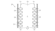
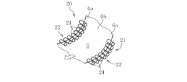
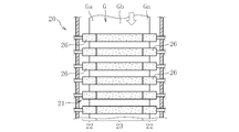
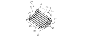
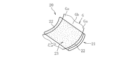
- FIG. It is a partial schematic side view of the manufacturing apparatus of the glass film which concerns on embodiment of this invention. It is a principal part front view of FIG. It is a principal part perspective view of FIG. It is a principal part perspective view of the manufacturing apparatus of the glass film which concerns on other embodiment of this invention. It is a principal part perspective view of the manufacturing apparatus of the glass film which concerns on other embodiment of this invention. It is a principal part front view of the manufacturing apparatus of the glass film which concerns on other embodiment of this invention. It is a principal part perspective view of the manufacturing apparatus of the glass film which concerns on other embodiment of this invention. It is a principal part front view of the manufacturing apparatus of the glass film which concerns on other embodiment of this invention.
- FIG. 1 is a partial schematic side view of a glass film manufacturing apparatus 1 according to an embodiment of the present invention.
- the manufacturing apparatus 1 shown in the figure includes a forming apparatus 10 for forming a glass film ribbon G, a direction changing device 20 provided on the downstream side of the forming apparatus 10, and a downstream side of the direction changing apparatus 20.
- At least an end cutting device 30 that cuts the width direction end region (both ends in the width direction) of the ribbon G is provided.
- a winder that winds the glass film ribbon G in a roll shape to obtain a roll body (glass roll) of the glass film, or by cutting the glass film ribbon G in the width direction.
- a width direction cutting device for obtaining a thin glass sheet having a predetermined size is further provided (all not shown).
- the forming apparatus 10 forms the glass film ribbon G by pulling the molten glass vertically downward, and includes a forming region 10A, a slow cooling region 10B, and a cooling region 10C in the interior from vertically upward to vertically downward. Are provided in order.
- a molded body 11 having a wedge-shaped cross section is disposed in the molding region 10A, and a plurality of roller bodies 12 are disposed at predetermined intervals in the slow cooling region 10B and the cooling region 10C.
- the roller body 12 is provided in pairs on the front surface side and the back surface side of the glass film ribbon G so as to sandwich the glass film ribbon G.
- roller bodies 12 (sets of roller bodies 12) respectively arranged in the slow cooling region 10B and the cooling region 10C, at least the uppermost portion of the slow cooling region 10B is cooled for cooling the glass film ribbon G. While functioning as a roller, it functions as a drive roller for pulling out the glass film ribbon G vertically downward.
- a part or all of the other roller bodies 12 arranged in the slow cooling region 10B and a part or all of the roller bodies 12 arranged in the cooling region 10C may be free-rolling rollers (guide rollers). Alternatively, a driving roller may be used.
- the forming apparatus 10 having such a configuration forms the glass film ribbon G as follows. First, when molten glass is supplied from a melting furnace (not shown) to the molded body 11, the molten glass overflows from the top of the molded body 11, and the overflowed molten glass travels along both side surfaces of the molded body 11 and then the molded body 11. Forming of the glass film ribbon G is started by joining at the lower end of the. Thereafter, the glass film ribbon G is continuously formed by continuously supplying the molten glass to the formed body 11. The glass film ribbon G formed in this way flows down as it is vertically downward, and is gradually cooled by passing through a slow cooling region 10B provided below the forming region 10A, and residual strain is removed. When the glass film ribbon G from which the residual strain has been removed passes through the cooling region 10C, the glass film ribbon G is cooled to a temperature of about room temperature.
- the method for forming the glass film ribbon G described above is a so-called overflow down draw method.
- the overflow down draw method since the molding of the glass film ribbon G proceeds while the surface is only in contact with the outside air (atmospheric gas in the molding apparatus 10), it is possible to ensure high flatness in the glass film ribbon G. There is an advantage that you can. Therefore, when using the glass film obtained from the said glass film ribbon G as a glass substrate for FPD, for example, it becomes easy to form a fine element and wiring on the surface accurately.
- the glass film ribbon G discharged from the lower end of the forming device 10 (passed through the cooling region 10C) is transferred (transferred) to the direction changing device 20, and the glass film ribbon G is transferred along the direction changing device 20.
- the traveling direction is converted from the vertical direction to the horizontal direction.
- the direction changing device 20 has a bending support means 21 that supports the glass film ribbon G in a state of being bent in the longitudinal direction.
- the bending support means 21 of the present embodiment supports the width direction end regions Ga and Ga without supporting the width direction central region Gb of the glass film ribbon G. It is comprised by the edge part support parts 22 and 22 of a row
- the end support portions 22 are arranged at predetermined intervals along the longitudinal direction of the glass film ribbon G so as to form an arcuate transfer path curved with a predetermined curvature, and the width direction of the glass film ribbon G It is comprised by the row
- all the roller bodies 24 constituting the end support portion 22 are constituted by drive rollers that are rotationally driven.
- the rotational speed of each roller body 24 is set to be approximately the same speed as the transfer speed (advance speed) of the glass film ribbon G to the downstream side.
- an elastic material soft material
- resin or rubber in order to suppress or prevent formation of scratches on the glass film ribbon G. It is desirable to do.
- the direction changing device 20 has the above configuration, when the glass film ribbon G is transferred downstream along the direction changing device 20 (direction changing step), the glass film ribbon G has an arc shape in the longitudinal direction. To curve. As described above, when the glass film ribbon G is curved in the longitudinal direction and the transfer to the downstream side proceeds, the traveling direction of the glass film ribbon G is converted from the vertical direction to the horizontal direction. And when the glass film ribbon G reaches
- the end cutting device 30 a so-called folding device, a laser cutting device, or the like can be used.
- the glass film ribbon G is divided
- the width direction end regions Ga and Ga are cut, the width direction is cut, but conversely, after the width direction cutting is performed, the width direction end regions are cut. Ga and Ga may be cut.
- the effective portion is limited to the central region Gb in the width direction of the glass film ribbon G. Therefore, as described above, the bending support means 21 is composed of two rows of end support portions 22 and 22 that support the width direction end regions Ga and Ga without supporting the width direction central region Gb of the glass film ribbon G. If comprised, the contact of the width direction center area
- the two rows of end support portions 22 and 22 are for supporting the width direction end regions Ga and Ga of the glass film ribbon G in contact with each other, and are constituted by a row of roller bodies 24 composed of drive rollers.
- the rotation speed of the roller body 24 is set to be substantially the same as the transfer speed of the glass film ribbon G to the downstream side, the direction change of the glass film ribbon G (transfer to the downstream side in the curved state) ) Proceeds as if the roller body 24 (end support 22) and the glass film ribbon G are integrated.
- the relative sliding movement of the glass film ribbon G and the edge part support part 22 is prevented as much as possible, it becomes difficult to form a micro defect in the width direction edge part area
- the end support 22 is idle. It may be configured only by the roller body 24 (guide roller), or a part may be configured by a rotationally driven roller body, and the other may be configured by an idled roller body.
- the glass film ribbon G When the thickness of the glass film ribbon G is less than 10 ⁇ m when the glass film ribbon G is curved and transferred in the above-described manner, the glass film ribbon G is caused by insufficient rigidity (strength). The bending in the width direction due to the weight of the glass film ribbon G increases. In this case, microdefects such as cracks are likely to occur due to unexpected contact between the bent portion and the manufacturing apparatus. Moreover, as for the glass film ribbon G shape
- the plate thickness at the center in the width direction exceeds 300 ⁇ m, the plate thickness of the width direction end region Ga becomes too thick, and it becomes difficult to curve the glass film ribbon G with a predetermined curvature. Therefore, as the forming apparatus 10, it is desirable to use an apparatus capable of forming a glass film ribbon G having a thickness of 10 ⁇ m or more and 300 ⁇ m or less at the center in the width direction (near the center).
- the molding apparatus 10 is more preferably capable of molding a glass film ribbon G having a thickness of 200 ⁇ m or less at the center in the width direction, and can be molded to 100 ⁇ m or less. Are more preferable, and those that can be molded to 50 ⁇ m or less are most preferable.
- this invention is not limited to this, Especially about the direction change apparatus 20, it is possible to give a various change. is there.
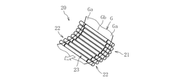
- FIG. 3A and 3B are perspective views of a main part of a glass film manufacturing apparatus according to another embodiment of the present invention. Both figures show a modification of the direction changing device 20 shown in FIG. 2.
- the curved support means 21 supports two rows of end portions that support the width direction end regions Ga and Ga of the glass film ribbon G. Parts 22 and 22 and a central support part 23 that can be interposed between the end support parts 22 and 22 and can support the central region Gb in the width direction of the glass film ribbon G. Reciprocating between a support position (FIG. 3a) that supports (contact support) the width direction central region Gb of the glass film ribbon G and a retreat position (FIG. 3b) that does not support the width direction central region Gb of the glass film ribbon G. It is configured to be possible.
- Such a configuration is preferably applicable when it is desired to stabilize the molding accuracy of the glass film ribbon G at an early stage after the molding of the glass film ribbon G is started.
- the leading edge of the glass film ribbon G is in a free state, so it is difficult to stabilize the forming accuracy. If the glass film ribbon G is not supported at all from the formation start stage of the glass film ribbon G, it takes a long time until the forming accuracy is stabilized, leading to a decrease in production efficiency and a decrease in yield. On the other hand, if the curved support means 21 has the central support portion 23 that can reciprocate in the above-described manner, the support / non-support of the width direction central region Gb of the glass film ribbon G can be easily switched. Can do.
- the central support unit 23 stands by at the support position. If 23 is retracted to the retracted position, it becomes difficult to form minute defects in the center region Gb in the width direction of the glass film ribbon G, that is, the effective portion, and until the molding accuracy of the glass film ribbon G is stabilized. The production time and the yield can be improved.
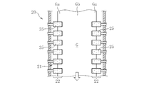
- the direction changing device 20 moves the glass film ribbon G from the vertical direction to the horizontal direction by bending and transferring the glass film ribbon G to the downstream side in a state where the width direction end regions Ga and Ga are supported in a non-contact manner.
- a roller body 25 having air supply holes (air injection holes) through which the end support portions 22 can inject air toward the glass film ribbon G as shown in FIGS. 4a and 4b, for example. It is obtained by configuring with As such a roller body 25, for example, a material formed of a porous material such as sintered metal, porous resin (foamed resin), ceramics, or the like can be used, or a through-hole is formed in a non-porous member.
- a drilled one can also be used.
- the roller body 25 is provided with at least an air supply hole having a directivity capable of imparting a floating force to the glass film ribbon G.
- an air supply hole having a directivity that can impart a downstream feed force to the glass film ribbon G may be provided.
- the glass film ribbon G bends in the downstream direction of the glass film ribbon G in a state where the width direction end regions Ga and Ga of the glass film ribbon G and the end support portion 22 of the bending support means 21 are not in contact with each other. Since the transfer proceeds, it is difficult to form minute defects in the width direction end regions Ga and Ga of the glass film ribbon G. As a result, it is possible to prevent as much as possible the adverse effect caused by the formation of micro defects in the width direction end regions Ga and Ga, reaching the width direction central region Gb. A film can be obtained.
- the bending support means 21 of the direction changing device 20 includes two rows of end support portions 22 for supporting the width direction end regions Ga and Ga of the glass film ribbon G in a non-contact manner. 22 and a central support portion 23 that is interposed between the end support portions 22 and 22 and supports the central region Gb in the width direction of the glass film ribbon G in a non-contact manner.
- two rows of end support portions 22 and 22 and a central support portion 23 are configured by a row of roller bodies 26 having air supply holes and extending so as to cross the glass film ribbon G in the width direction. is doing.
- each roller body 26 constituting the central support portion 23 has an air supply hole, during the curved transfer of the glass film ribbon G, between the central support portion 26 of the curved support means 21 and the glass film ribbon G. An air layer can be formed. If such an air layer is formed, it is possible to absorb a change in stress based on a difference in plate thickness between each part of the glass film ribbon G. Therefore, it is possible to improve the molding accuracy of the glass film ribbon G and consequently the glass film.
- the curved support means 21 shown in FIG. 5a and FIG. 5b has two rows of end support portions 22 and 22 and a central support portion 23 that are integrally provided.
- the central support portion 23 supports (non-contact support) the width direction central region Gb of the glass film ribbon G, and the width direction central region Gb of the glass film ribbon G. It is also possible to configure so as to reciprocate between a retracted position that does not support.
- the two end support portions 22 and 22 and the center support portion 23 are both composed of a row of roller bodies arranged at predetermined intervals along the longitudinal direction of the glass film ribbon G.
- One or both of the two end support portions 22 and 22 and the central support portion 23 are conveyors that extend in a curved manner along the longitudinal direction of the glass film ribbon G, as shown in FIG. It is also possible to configure.
- FIG. 6a shows an example of the case where the bending support means 21 is composed of only two rows of end support portions 22 and 22, and each end support portion 22 is composed of a conveyor.
- 6b shows an example in which the curved support means 21 is composed of two rows of end support portions 22 and 22 and a central support portion 23, and both support portions 22 and 23 are configured by a conveyor. .
- the present invention is applied to the glass film manufacturing apparatus 1 incorporating the molding apparatus 10 for molding the glass film ribbon G by the so-called overflow down draw method. It can also be preferably applied to a glass film manufacturing apparatus 1 incorporating a forming apparatus for forming a glass film ribbon G by a so-called redraw method in which a glass base material for subsequent processing is heated and stretched.
Landscapes
- Chemical & Material Sciences (AREA)
- Engineering & Computer Science (AREA)
- Materials Engineering (AREA)
- Organic Chemistry (AREA)
- Re-Forming, After-Treatment, Cutting And Transporting Of Glass Products (AREA)
- Laminated Bodies (AREA)
- Electroluminescent Light Sources (AREA)
- Casting Or Compression Moulding Of Plastics Or The Like (AREA)
Abstract
Description
10 成形装置
10A 成形領域
10B 徐冷領域
10C 冷却領域
20 方向変換装置
21 湾曲支持手段
22 端部支持部
23 中央支持部
24 ローラ体
25 ローラ体
30 端部切断装置
G ガラスフィルムリボン
Ga 幅方向端部領域
Gb 幅方向中央領域
Claims (12)
- 成形装置から鉛直下方に引き出されたガラスフィルムリボンを、長尺方向に湾曲させながら下流側に移送することにより、前記ガラスフィルムリボンの進行方向を鉛直方向から水平方向に変換する方向変換装置を備えたガラスフィルムの製造装置において、
前記方向変換装置は、前記ガラスフィルムリボンを長尺方向に湾曲した状態で支持する湾曲支持手段を有し、該湾曲支持手段は、前記ガラスフィルムリボンの幅方向中央領域を支持せずに幅方向端部領域を支持する二列の端部支持部で構成されていることを特徴とするガラスフィルムの製造装置。 - 成形装置から鉛直下方に引き出されたガラスフィルムリボンを、長尺方向に湾曲させながら下流側に移送することにより、前記ガラスフィルムリボンの進行方向を鉛直方向から水平方向に変換する方向変換装置を備えたガラスフィルムの製造装置において、
前記方向変換装置は、前記ガラスフィルムリボンを長尺方向に湾曲した状態で支持する湾曲支持手段を有し、該湾曲支持手段は、前記ガラスフィルムリボンの幅方向端部領域を支持する二列の端部支持部と、該二列の端部支持部の間に介在して、前記ガラスフィルムリボンの幅方向中央領域を支持可能な中央支持部とを有し、該中央支持部は、前記ガラスフィルムリボンの幅方向中央領域を支持する支持位置と、前記ガラスフィルムリボンの幅方向中央領域を支持しない退避位置との間を往復動可能に構成されていることを特徴とするガラスフィルムの製造装置。 - 成形装置から鉛直下方に引き出されたガラスフィルムリボンを、長尺方向に湾曲させながら下流側に移送することにより、前記ガラスフィルムリボンの進行方向を鉛直方向から水平方向に変換する方向変換装置を備えたガラスフィルムの製造装置において、
前記方向変換装置は、前記ガラスフィルムリボンを長尺方向に湾曲した状態で支持する湾曲支持手段を有し、該湾曲支持手段は、前記ガラスフィルムリボンの幅方向端部領域を支持する二列の端部支持部と、該二列の端部支持部の間に介在し、前記ガラスフィルムリボンの幅方向中央領域を非接触支持可能な中央支持部とを備えることを特徴とするガラスフィルムの製造装置。 - 前記中央支持部は、前記ガラスフィルムリボンの幅方向中央領域を非接触支持する支持位置と、前記ガラスフィルムリボンの幅方向中央領域を支持しない退避位置との間を往復動可能に構成されていることを特徴とする請求項3に記載のガラスフィルムの製造装置。
- 前記中央支持部は、前記ガラスフィルムリボンに向けてエアーを噴射するエアー供給路を有することを特徴とする請求項2~4の何れか一項に記載のガラスフィルムの製造装置。
- 前記二列の端部支持部は、前記ガラスフィルムリボンに向けてエアーを噴射するエアー供給路を有することを特徴とする請求項1~5の何れか一項に記載のガラスフィルムの製造装置。
- 前記二列の端部支持部は、前記ガラスフィルムリボンの幅方向端部領域を接触支持するものであり、かつ前記ガラスフィルムリボンの下流側への移送速度と略同一の速度にて駆動するように構成されていることを特徴とする請求項1~5の何れか一項に記載のガラスフィルムの製造装置。
- 前記ガラスフィルムリボンは、幅方向中央部の板厚が10μm以上300μm以下のものである請求項1~7の何れか一項に記載のガラスフィルムの製造装置。
- 前記成形装置は、オーバーフローダウンドロー法により前記ガラスフィルムリボンを成形するものである請求項1~8の何れか一項に記載のガラスフィルムの製造装置。
- 成形装置から鉛直下方に引き出されたガラスフィルムリボンを長尺方向に湾曲させながら下流側に移送することにより、前記ガラスフィルムリボンの進行方向を鉛直方向から水平方向に変換する方向変換工程を含むガラスフィルムの製造方法において、
前記方向変換工程では、前記ガラスフィルムリボンの幅方向端部領域を支持すると共に、前記ガラスフィルムリボンの幅方向中央領域を支持しないことを特徴とするガラスフィルムの製造方法。 - 成形装置から鉛直下方に引き出されたガラスフィルムリボンを長尺方向に湾曲させながら下流側に移送することにより、前記ガラスフィルムリボンの進行方向を鉛直方向から水平方向に変換する方向変換工程を含むガラスフィルムの製造方法において、
前記方向変換工程では、前記ガラスフィルムリボンの幅方向端部領域を支持すると共に、前記ガラスフィルムリボンの幅方向中央領域を支持する状態と支持しない状態を切り換えることを特徴とするガラスフィルムの製造方法。 - 成形装置から鉛直下方に引き出されたガラスフィルムリボンを長尺方向に湾曲させながら下流側に移送することにより、前記ガラスフィルムリボンの進行方向を鉛直方向から水平方向に変換する方向変換工程を含むガラスフィルムの製造方法において、
前記方向変換工程では、前記ガラスフィルムリボンの幅方向端部領域を支持すると共に、前記ガラスフィルムリボンの幅方向中央領域を非接触支持することを特徴とするガラスフィルムの製造方法。
Priority Applications (2)
| Application Number | Priority Date | Filing Date | Title |
|---|---|---|---|
| CN201180026297.3A CN102917989B (zh) | 2010-07-23 | 2011-07-15 | 玻璃膜的制造装置及制造方法 |
| KR1020127022391A KR101823427B1 (ko) | 2010-07-23 | 2011-07-15 | 유리 필름의 제조 장치 및 제조 방법 |
Applications Claiming Priority (2)
| Application Number | Priority Date | Filing Date | Title |
|---|---|---|---|
| JP2010165894A JP5645063B2 (ja) | 2010-07-23 | 2010-07-23 | ガラスフィルムの製造装置および製造方法 |
| JP2010-165894 | 2010-07-23 |
Publications (1)
| Publication Number | Publication Date |
|---|---|
| WO2012011439A1 true WO2012011439A1 (ja) | 2012-01-26 |
Family
ID=45496862
Family Applications (1)
| Application Number | Title | Priority Date | Filing Date |
|---|---|---|---|
| PCT/JP2011/066190 Ceased WO2012011439A1 (ja) | 2010-07-23 | 2011-07-15 | ガラスフィルムの製造装置および製造方法 |
Country Status (6)
| Country | Link |
|---|---|
| US (1) | US8701442B2 (ja) |
| JP (1) | JP5645063B2 (ja) |
| KR (1) | KR101823427B1 (ja) |
| CN (1) | CN102917989B (ja) |
| TW (1) | TWI535671B (ja) |
| WO (1) | WO2012011439A1 (ja) |
Cited By (3)
| Publication number | Priority date | Publication date | Assignee | Title |
|---|---|---|---|---|
| CN102785934A (zh) * | 2012-07-31 | 2012-11-21 | 芜湖耀华玻璃园艺有限公司 | 大型玻璃的传送装置 |
| JP2013079188A (ja) * | 2011-10-03 | 2013-05-02 | Corning Inc | ガラス製造プロセスにおいて使用される牽引ローラおよびこれを組み込んだガラス製造プロセス |
| WO2013099676A1 (ja) * | 2011-12-26 | 2013-07-04 | 日本電気硝子株式会社 | 帯状ガラスの製造方法 |
Families Citing this family (17)
| Publication number | Priority date | Publication date | Assignee | Title |
|---|---|---|---|---|
| JP5532507B2 (ja) * | 2008-10-01 | 2014-06-25 | 日本電気硝子株式会社 | ガラスロール及びガラスロールの処理方法 |
| US8656738B2 (en) * | 2008-10-31 | 2014-02-25 | Corning Incorporated | Glass sheet separating device |
| US9199816B2 (en) * | 2010-11-04 | 2015-12-01 | Corning Incorporated | Methods and apparatus for guiding flexible glass ribbons |
| JP2015187041A (ja) * | 2012-08-09 | 2015-10-29 | 旭硝子株式会社 | 薄板ガラスの製造方法 |
| TWI597245B (zh) * | 2012-09-25 | 2017-09-01 | 康寧公司 | 處理連續玻璃帶之方法 |
| EP3040317B1 (en) * | 2013-08-28 | 2019-09-25 | Nippon Electric Glass Co., Ltd. | Glass film ribbon manufacturing method and glass film ribbon manufacturing device |
| JP6478084B2 (ja) * | 2014-03-20 | 2019-03-06 | 日本電気硝子株式会社 | ガラスフィルムの搬送方法、及びガラスフィルムの搬送装置 |
| JP6323716B2 (ja) * | 2014-12-17 | 2018-05-16 | 日本電気硝子株式会社 | ガラスフィルムの製造方法 |
| JP2017109881A (ja) * | 2015-12-14 | 2017-06-22 | 日本電気硝子株式会社 | 板ガラスの製造装置、板ガラスの製造方法および板ガラスの搬送装置 |
| JP6675587B2 (ja) | 2016-10-11 | 2020-04-01 | 日本電気硝子株式会社 | 帯状ガラスフィルムの製造方法及び製造装置 |
| JP6811671B2 (ja) * | 2017-03-31 | 2021-01-13 | 日東電工株式会社 | ウエブ送給方法およびそれに用いるウエブ送給装置 |
| JP7033269B2 (ja) * | 2017-12-11 | 2022-03-10 | 日本電気硝子株式会社 | 帯状ガラスの製造方法、及び帯状ガラスの製造装置 |
| DE112019000619T5 (de) * | 2018-01-31 | 2020-10-15 | Nippon Electric Glass Co., Ltd. | Glasrolle, Glasrollenherstellungsverfahren und Qualitätsbewertungsverfahren |
| CN108383358A (zh) * | 2018-03-30 | 2018-08-10 | 安徽福莱特光伏玻璃有限公司 | 一种改进的玻璃压延机 |
| CN113631372B (zh) * | 2019-03-29 | 2024-01-30 | 日东电工株式会社 | 玻璃膜复合体的搬送方法 |
| JP7450851B2 (ja) * | 2020-02-25 | 2024-03-18 | 日本電気硝子株式会社 | ガラスフィルムの製造方法 |
| JP7486044B2 (ja) * | 2020-03-17 | 2024-05-17 | 日本電気硝子株式会社 | 帯状ガラスフィルムの製造方法 |
Citations (2)
| Publication number | Priority date | Publication date | Assignee | Title |
|---|---|---|---|---|
| JP2009511398A (ja) * | 2005-05-10 | 2009-03-19 | コーニング インコーポレイテッド | ガラスシートの製造方法 |
| JP2010511581A (ja) * | 2006-11-30 | 2010-04-15 | コーニング インコーポレイテッド | 形状安定性が向上した板ガラスの形成 |
Family Cites Families (9)
| Publication number | Priority date | Publication date | Assignee | Title |
|---|---|---|---|---|
| US3771987A (en) * | 1971-04-05 | 1973-11-13 | Libbey Owens Ford Co | Apparatus for conveying a glass ribbon |
| DE3067590D1 (en) * | 1980-01-02 | 1984-05-24 | Agfa Gevaert Nv | Web controlling apparatus |
| JP3638042B2 (ja) | 1995-08-11 | 2005-04-13 | 日本電気硝子株式会社 | 薄板ガラスの切断方法及び装置 |
| US6004432A (en) * | 1998-01-28 | 1999-12-21 | Beloit Technologies, Inc. | Sheet turn with vectored air supply |
| DE19918936A1 (de) * | 1999-04-27 | 2000-11-02 | Schott Glas | Verfahren und Vorrichtung zur Herstellung von Einzelglasscheiben |
| DE10045479A1 (de) * | 2000-09-14 | 2002-04-04 | Schott Glas | Verfahren und Vorrichtung zum kontaktlosen Lagern und Transportieren von Flachglas |
| DE10156961B4 (de) * | 2001-11-20 | 2005-12-01 | Schott Ag | Vorrichtung zur Unterstützung eines Glasbandes |
| US20060042314A1 (en) * | 2004-08-27 | 2006-03-02 | Abbott John S Iii | Noncontact glass sheet stabilization device used in fusion forming of a glass sheet |
| US8397539B2 (en) * | 2010-02-18 | 2013-03-19 | Corning Incorporated | Non-contact dancer mechanisms, web isolation apparatuses and methods for using the same |
-
2010
- 2010-07-23 JP JP2010165894A patent/JP5645063B2/ja active Active
-
2011
- 2011-07-15 WO PCT/JP2011/066190 patent/WO2012011439A1/ja not_active Ceased
- 2011-07-15 CN CN201180026297.3A patent/CN102917989B/zh active Active
- 2011-07-15 KR KR1020127022391A patent/KR101823427B1/ko active Active
- 2011-07-19 US US13/185,687 patent/US8701442B2/en active Active
- 2011-07-21 TW TW100125793A patent/TWI535671B/zh active
Patent Citations (2)
| Publication number | Priority date | Publication date | Assignee | Title |
|---|---|---|---|---|
| JP2009511398A (ja) * | 2005-05-10 | 2009-03-19 | コーニング インコーポレイテッド | ガラスシートの製造方法 |
| JP2010511581A (ja) * | 2006-11-30 | 2010-04-15 | コーニング インコーポレイテッド | 形状安定性が向上した板ガラスの形成 |
Cited By (4)
| Publication number | Priority date | Publication date | Assignee | Title |
|---|---|---|---|---|
| JP2013079188A (ja) * | 2011-10-03 | 2013-05-02 | Corning Inc | ガラス製造プロセスにおいて使用される牽引ローラおよびこれを組み込んだガラス製造プロセス |
| WO2013099676A1 (ja) * | 2011-12-26 | 2013-07-04 | 日本電気硝子株式会社 | 帯状ガラスの製造方法 |
| US9260336B2 (en) | 2011-12-26 | 2016-02-16 | Nippon Electric Glass Co., Ltd. | Method for manufacturing band-shaped glass |
| CN102785934A (zh) * | 2012-07-31 | 2012-11-21 | 芜湖耀华玻璃园艺有限公司 | 大型玻璃的传送装置 |
Also Published As
| Publication number | Publication date |
|---|---|
| JP5645063B2 (ja) | 2014-12-24 |
| JP2012025624A (ja) | 2012-02-09 |
| US8701442B2 (en) | 2014-04-22 |
| US20120024929A1 (en) | 2012-02-02 |
| TW201208993A (en) | 2012-03-01 |
| CN102917989B (zh) | 2015-11-25 |
| KR101823427B1 (ko) | 2018-01-30 |
| KR20130094175A (ko) | 2013-08-23 |
| CN102917989A (zh) | 2013-02-06 |
| TWI535671B (zh) | 2016-06-01 |
Similar Documents
| Publication | Publication Date | Title |
|---|---|---|
| JP5645063B2 (ja) | ガラスフィルムの製造装置および製造方法 | |
| KR101736262B1 (ko) | 유리 필름의 제조방법 및 그 제조장치 | |
| JP5679324B2 (ja) | ガラスロールの製造方法および製造装置 | |
| CN102933513B (zh) | 带状玻璃膜制造方法及带状玻璃膜制造装置 | |
| TWI534107B (zh) | 生產玻璃板之方法 | |
| JP6331087B2 (ja) | ガラスフィルムリボン製造方法及びガラスフィルムリボン製造装置 | |
| CN103261107B (zh) | 玻璃板成形品的制造方法及玻璃板成形品的制造装置 | |
| JP6392238B2 (ja) | ガラス板平坦化のための装置及びガラス板を平坦化する方法 | |
| JP2015044710A (ja) | ガラスフィルムリボン製造装置及びガラスフィルムリボン製造方法並びにガラスロール | |
| JP2015044709A (ja) | ガラスフィルムリボン製造方法及びガラスフィルムリボン製造装置並びにガラスロール | |
| JP5500377B2 (ja) | ガラスフィルムの製造方法及び製造装置 |
Legal Events
| Date | Code | Title | Description |
|---|---|---|---|
| WWE | Wipo information: entry into national phase |
Ref document number: 201180026297.3 Country of ref document: CN |
|
| 121 | Ep: the epo has been informed by wipo that ep was designated in this application |
Ref document number: 11809609 Country of ref document: EP Kind code of ref document: A1 |
|
| ENP | Entry into the national phase |
Ref document number: 20127022391 Country of ref document: KR Kind code of ref document: A |
|
| NENP | Non-entry into the national phase |
Ref country code: DE |
|
| 122 | Ep: pct application non-entry in european phase |
Ref document number: 11809609 Country of ref document: EP Kind code of ref document: A1 |