WO2012011256A1 - 発振装置および電子機器 - Google Patents
発振装置および電子機器 Download PDFInfo
- Publication number
- WO2012011256A1 WO2012011256A1 PCT/JP2011/004035 JP2011004035W WO2012011256A1 WO 2012011256 A1 WO2012011256 A1 WO 2012011256A1 JP 2011004035 W JP2011004035 W JP 2011004035W WO 2012011256 A1 WO2012011256 A1 WO 2012011256A1
- Authority
- WO
- WIPO (PCT)
- Prior art keywords
- elastic
- oscillation device
- electroacoustic transducer
- elastic vibration
- piezoelectric
- Prior art date
Links
- 230000005684 electric field Effects 0.000 claims abstract description 11
- 230000010355 oscillation Effects 0.000 claims description 44
- 238000005259 measurement Methods 0.000 claims description 6
- 230000004044 response Effects 0.000 claims description 2
- 239000000463 material Substances 0.000 description 21
- 239000000919 ceramic Substances 0.000 description 7
- 238000006243 chemical reaction Methods 0.000 description 6
- 230000009471 action Effects 0.000 description 5
- 230000000694 effects Effects 0.000 description 5
- 230000005520 electrodynamics Effects 0.000 description 5
- 230000010287 polarization Effects 0.000 description 5
- 239000004332 silver Substances 0.000 description 5
- KDLHZDBZIXYQEI-UHFFFAOYSA-N Palladium Chemical compound [Pd] KDLHZDBZIXYQEI-UHFFFAOYSA-N 0.000 description 4
- 238000004519 manufacturing process Methods 0.000 description 4
- 239000011159 matrix material Substances 0.000 description 4
- 238000000034 method Methods 0.000 description 4
- 229910052709 silver Inorganic materials 0.000 description 4
- 230000008901 benefit Effects 0.000 description 3
- 238000010586 diagram Methods 0.000 description 3
- 239000010408 film Substances 0.000 description 3
- 229910052451 lead zirconate titanate Inorganic materials 0.000 description 3
- 238000012986 modification Methods 0.000 description 3
- 230000004048 modification Effects 0.000 description 3
- 229910002113 barium titanate Inorganic materials 0.000 description 2
- 238000001514 detection method Methods 0.000 description 2
- 238000011161 development Methods 0.000 description 2
- 238000006073 displacement reaction Methods 0.000 description 2
- 230000001771 impaired effect Effects 0.000 description 2
- HFGPZNIAWCZYJU-UHFFFAOYSA-N lead zirconate titanate Chemical compound [O-2].[O-2].[O-2].[O-2].[O-2].[Ti+4].[Zr+4].[Pb+2] HFGPZNIAWCZYJU-UHFFFAOYSA-N 0.000 description 2
- 229910052763 palladium Inorganic materials 0.000 description 2
- 238000005192 partition Methods 0.000 description 2
- 239000010935 stainless steel Substances 0.000 description 2
- 229910001220 stainless steel Inorganic materials 0.000 description 2
- 239000010409 thin film Substances 0.000 description 2
- 229910001316 Ag alloy Inorganic materials 0.000 description 1
- 229910001369 Brass Inorganic materials 0.000 description 1
- 229910000906 Bronze Inorganic materials 0.000 description 1
- 239000004593 Epoxy Substances 0.000 description 1
- 229910001252 Pd alloy Inorganic materials 0.000 description 1
- OAICVXFJPJFONN-UHFFFAOYSA-N Phosphorus Chemical compound [P] OAICVXFJPJFONN-UHFFFAOYSA-N 0.000 description 1
- 239000000853 adhesive Substances 0.000 description 1
- 230000001070 adhesive effect Effects 0.000 description 1
- 230000002238 attenuated effect Effects 0.000 description 1
- JRPBQTZRNDNNOP-UHFFFAOYSA-N barium titanate Chemical compound [Ba+2].[Ba+2].[O-][Ti]([O-])([O-])[O-] JRPBQTZRNDNNOP-UHFFFAOYSA-N 0.000 description 1
- 239000010951 brass Substances 0.000 description 1
- 239000010974 bronze Substances 0.000 description 1
- 230000006835 compression Effects 0.000 description 1
- 238000007906 compression Methods 0.000 description 1
- 239000004020 conductor Substances 0.000 description 1
- 239000000470 constituent Substances 0.000 description 1
- 230000008602 contraction Effects 0.000 description 1
- KUNSUQLRTQLHQQ-UHFFFAOYSA-N copper tin Chemical compound [Cu].[Sn] KUNSUQLRTQLHQQ-UHFFFAOYSA-N 0.000 description 1
- 238000013461 design Methods 0.000 description 1
- 239000012530 fluid Substances 0.000 description 1
- 229910052751 metal Inorganic materials 0.000 description 1
- 239000002184 metal Substances 0.000 description 1
- 230000003647 oxidation Effects 0.000 description 1
- 238000007254 oxidation reaction Methods 0.000 description 1
- 238000012545 processing Methods 0.000 description 1
- 230000000644 propagated effect Effects 0.000 description 1
- 230000001902 propagating effect Effects 0.000 description 1
- 239000011347 resin Substances 0.000 description 1
- 229920005989 resin Polymers 0.000 description 1
- 230000000452 restraining effect Effects 0.000 description 1
- 230000035939 shock Effects 0.000 description 1
Images


Classifications
-
- H—ELECTRICITY
- H02—GENERATION; CONVERSION OR DISTRIBUTION OF ELECTRIC POWER
- H02N—ELECTRIC MACHINES NOT OTHERWISE PROVIDED FOR
- H02N2/00—Electric machines in general using piezoelectric effect, electrostriction or magnetostriction
- H02N2/0005—Electric machines in general using piezoelectric effect, electrostriction or magnetostriction producing non-specific motion; Details common to machines covered by H02N2/02 - H02N2/16
- H02N2/001—Driving devices, e.g. vibrators
-
- H—ELECTRICITY
- H04—ELECTRIC COMMUNICATION TECHNIQUE
- H04R—LOUDSPEAKERS, MICROPHONES, GRAMOPHONE PICK-UPS OR LIKE ACOUSTIC ELECTROMECHANICAL TRANSDUCERS; DEAF-AID SETS; PUBLIC ADDRESS SYSTEMS
- H04R17/00—Piezoelectric transducers; Electrostrictive transducers
-
- G—PHYSICS
- G01—MEASURING; TESTING
- G01S—RADIO DIRECTION-FINDING; RADIO NAVIGATION; DETERMINING DISTANCE OR VELOCITY BY USE OF RADIO WAVES; LOCATING OR PRESENCE-DETECTING BY USE OF THE REFLECTION OR RERADIATION OF RADIO WAVES; ANALOGOUS ARRANGEMENTS USING OTHER WAVES
- G01S15/00—Systems using the reflection or reradiation of acoustic waves, e.g. sonar systems
- G01S15/02—Systems using the reflection or reradiation of acoustic waves, e.g. sonar systems using reflection of acoustic waves
- G01S15/06—Systems determining the position data of a target
- G01S15/08—Systems for measuring distance only
-
- H—ELECTRICITY
- H04—ELECTRIC COMMUNICATION TECHNIQUE
- H04R—LOUDSPEAKERS, MICROPHONES, GRAMOPHONE PICK-UPS OR LIKE ACOUSTIC ELECTROMECHANICAL TRANSDUCERS; DEAF-AID SETS; PUBLIC ADDRESS SYSTEMS
- H04R2217/00—Details of magnetostrictive, piezoelectric, or electrostrictive transducers covered by H04R15/00 or H04R17/00 but not provided for in any of their subgroups
- H04R2217/03—Parametric transducers where sound is generated or captured by the acoustic demodulation of amplitude modulated ultrasonic waves
-
- H—ELECTRICITY
- H04—ELECTRIC COMMUNICATION TECHNIQUE
- H04R—LOUDSPEAKERS, MICROPHONES, GRAMOPHONE PICK-UPS OR LIKE ACOUSTIC ELECTROMECHANICAL TRANSDUCERS; DEAF-AID SETS; PUBLIC ADDRESS SYSTEMS
- H04R2440/00—Bending wave transducers covered by H04R, not provided for in its groups
- H04R2440/05—Aspects relating to the positioning and way or means of mounting of exciters to resonant bending wave panels
-
- H—ELECTRICITY
- H04—ELECTRIC COMMUNICATION TECHNIQUE
- H04R—LOUDSPEAKERS, MICROPHONES, GRAMOPHONE PICK-UPS OR LIKE ACOUSTIC ELECTROMECHANICAL TRANSDUCERS; DEAF-AID SETS; PUBLIC ADDRESS SYSTEMS
- H04R2499/00—Aspects covered by H04R or H04S not otherwise provided for in their subgroups
- H04R2499/10—General applications
- H04R2499/11—Transducers incorporated or for use in hand-held devices, e.g. mobile phones, PDA's, camera's
Definitions
- the present invention relates to an oscillating device including a piezoelectric vibrator, and more particularly to an oscillating device in which a piezoelectric vibrator is mounted on an elastic diaphragm, and an electronic apparatus having the oscillating device.
- electrodynamic electroacoustic transducers are used as electroacoustic transducers in electronic devices such as mobile phones.
- This electrodynamic electroacoustic transducer is composed of a permanent magnet, a voice coil, and a diaphragm.
- Patent Documents 1 and 2 describe using a piezoelectric vibrator as an electroacoustic transducer.
- An oscillation device using a piezoelectric vibrator generates a vibration amplitude by an electrostrictive action by inputting an electric signal by using a piezoelectric effect of a piezoelectric material.
- the electrodynamic electroacoustic transducer generates vibration by a piston-type forward / backward movement, whereas the oscillation device using the piezoelectric vibrator has a bending-type vibration state and thus has a small amplitude. For this reason, it is superior in reducing the thickness of the electrodynamic electroacoustic transducer described above.
- the oscillation frequency which is one of the physical indicators of the oscillation device, depends on the shape of the vibrator. For this reason, in the case of an oscillation device using a piezoelectric vibrator, an oscillation frequency having a specific peak value tends to be obtained, and it is difficult to freely adjust the oscillation frequency.
- the present invention has been made in view of the above-described problems, and provides an oscillation device capable of freely adjusting the peak value of the oscillation frequency for each of a plurality of elastic vibration areas.
- the oscillation device of the present invention is supported by an elastic diaphragm that is divided into a plurality of elastic vibration areas by a slit, a support member that supports the plurality of elastic vibration areas at a position that is not a slit, and a support member.
- a plurality of piezoelectric vibrators that are individually attached to at least a part of the plurality of elastic vibration areas and vibrate and contract in response to application of an electric field.
- a first electronic device of the present invention includes the above-described oscillation device and an oscillation drive unit that causes the oscillation device to output an audible sound wave.
- a second electronic device includes the above-described oscillation device, an ultrasonic detection unit that detects an ultrasonic wave oscillated from the oscillation device and reflected by the measurement object, and from the detected ultrasonic wave to the measurement object.
- a distance measuring unit for calculating a distance.
- the peak value of the oscillation frequency can be freely adjusted for each of a plurality of elastic vibration areas.
- FIG. 1 is a schematic top view showing an electroacoustic transducer 100 as an oscillation device of the present embodiment
- FIG. 2 is a schematic perspective view
- FIG. 3 is a schematic cross-sectional view.
- the electroacoustic transducer 100 includes an elastic diaphragm 110 divided into a plurality of elastic vibration areas 112 by a slit 111 having a predetermined shape, and a plurality of elastic vibration areas 112. Is applied to at least a part of a plurality of elastic vibration sections 112 supported by the center support shaft 131 and the center support shaft 131, and a central support shaft 131 that is a support member that supports the magnetic field at a position other than the slit 111. And a plurality of piezoelectric vibrators 120 that vibrate and contract.
- the slit means a notch and does not necessarily have a width. A portion of the elastic vibration area 112 that is supported by the center support shaft 131 is a cut end portion.
- the elastic diaphragm 110 is formed in a circular shape, and is divided into a plurality of sector-shaped elastic vibration areas 112 by a plurality of radial slits 111. As shown in FIG. 3, the plurality of sector-shaped elastic vibration areas 112 are supported by a center support shaft 131 at the center of the elastic diaphragm 110.
- the plurality of sector-shaped elastic vibration areas 112 are formed in the same shape.
- the plurality of piezoelectric vibrators 120 attached to the plurality of elastic vibration areas 112 are also formed in disks having the same shape.
- the circular elastic diaphragm 110 is divided into a plurality of elastic vibration areas 112 having the same shape by a plurality of radial slits 111. ing.
- the plurality of elastic vibration areas 112 are cantilevered by a cylindrical center support shaft 131 at the center of the elastic vibration plate 110.
- An annular support body 132 is formed on the outer periphery of the circular elastic diaphragm 110.
- the main surface on one side of the piezoelectric vibrator 120 is constrained by the elastic vibration section 112, whereby the section vibrator 113 is formed.
- a plurality of segmented vibrators 113 are arranged so as to surround the center support shaft 131.
- the piezoelectric vibrator 120 of each sectional vibrator 113 has the upper and lower main surfaces of the piezoelectric layer 121 made of a piezoelectric material constrained by the upper electrode layer 122 and the lower electrode layer 123. And is joined to the elastic vibration area 112.
- the upper / lower electrode layers 122 and 123 are connected to the control unit 140 by lead wires 124.
- the piezoelectric vibrator 120 is driven in an audible region or an ultrasonic region by an electric field applied from the control unit 140.
- the material constituting the piezoelectric layer 121 of the present embodiment is not particularly limited as long as it is a material having a piezoelectric effect, but is not particularly limited, but a material having high electromechanical conversion efficiency, for example, lead zirconate titanate (PZT). ) And barium titanate (BaTiO3).
- PZT lead zirconate titanate
- BaTiO3 barium titanate
- the thickness of the piezoelectric layer 121 is not particularly limited, but is preferably 10 ⁇ m or more and 500 ⁇ m or less.
- the piezoelectric layer 121 may be chipped or damaged due to weak mechanical strength during handling. Handling of the piezoelectric layer 121 becomes difficult.
- the conversion efficiency for converting electrical energy into mechanical energy is remarkably lowered, and sufficient performance as the electroacoustic transducer 100 cannot be obtained.
- the conversion efficiency depends on the electric field strength. Since this electric field strength is expressed by (input voltage) / (thickness with respect to the polarization direction), an increase in thickness inevitably leads to a decrease in conversion efficiency.
- an upper electrode layer 122 and a lower electrode layer 123 are formed on the main surface in order to generate an electric field.
- the upper electrode layer 122 and the lower electrode layer 123 are not particularly limited as long as they are materials having electrical conductivity, but it is preferable to use silver or silver / palladium. Silver is used as a general-purpose electrode layer with low resistance, and has advantages in manufacturing process and cost.
- the thicknesses of the upper electrode layer 122 and the lower electrode layer 123 are not particularly limited, but the thickness is preferably 1 ⁇ m or more and 50 ⁇ m or less.
- the thickness of the upper electrode layer 122 and the lower electrode layers 122 and 123 is less than 1 ⁇ m, the upper electrode layer 122 and the lower electrode layer 123 are thin, so that they cannot be formed uniformly, and conversion efficiency may be reduced. There is sex.
- As a technique for forming the thin film upper electrode layer 122 and the lower electrode layer 123 there is a method of applying the paste in a paste form.
- the surface state is a satin surface, so that the wet state at the time of application is poor, and a uniform electrode film cannot be formed without a certain thickness.
- the film thickness of the upper electrode layer 122 and the lower electrode layer 123 exceeds 100 ⁇ m, there is no particular problem in manufacturing, but the piezoelectric film material in which the upper electrode layer 122 and the lower electrode layer 123 are the piezoelectric layer 121 is used. As a result, the energy conversion efficiency is lowered.
- one main surface is constrained by the elastic vibration area 112.
- the elastic vibration area 112 propagates vibration generated from the piezoelectric vibrator 120 to the annular support 132.
- the elastic vibration area 112 has a function of adjusting the basic resonance frequency of the piezoelectric vibrator 120.
- the mechanical basic resonance frequency f of the segmented resonator 113 depends on the load weight and compliance, as shown by the following equation.
- the basic resonance frequency can be controlled by controlling the rigidity of the piezoelectric vibrator 120.
- the fundamental resonance frequency can be shifted to a low frequency.
- the fundamental resonance frequency can be shifted to a high range by selecting a material having a high elastic modulus or increasing the thickness of the elastic vibration area 112.
- the basic resonance frequency was controlled by the shape and material of the piezoelectric vibrator 120, there were problems in design constraints, cost, and reliability.
- the basic resonance frequency can be easily adjusted to a desired value by changing the elastic vibration area 112 which is a constituent member.
- the material constituting the elastic diaphragm 110 is not particularly limited as long as it is a material having a high elastic modulus with respect to a ceramic that is a brittle material such as metal or resin, but phosphor bronze or stainless steel from the viewpoint of workability and cost.
- General-purpose materials such as are suitable.
- the thickness of the elastic diaphragm 110 is preferably 5 ⁇ m or more and 1000 ⁇ m or less. When the thickness is less than 5 ⁇ m, the mechanical strength of the elastic diaphragm 110 is weak, and the function as a restraining member may be impaired. Further, due to a decrease in processing accuracy, an error in the mechanical vibration characteristics of the piezoelectric vibrator 120 occurs between manufacturing lots.
- the elastic diaphragm 110 of the present embodiment preferably has a longitudinal elastic modulus, which is an index indicating the rigidity of the material, of 1 GPa or more and 500 GPa or less. As described above, when the rigidity of the elastic diaphragm 110 is excessively low or excessively high, there is a problem that characteristics and reliability are impaired as a mechanical vibrator.
- the elastic diaphragm 110 of the electroacoustic transducer 100 of this embodiment is directly joined to the center support shaft 131.
- the center support shaft 131 serves as a fixed end, and the material thereof must be a material having high rigidity with respect to the elastic diaphragm 110.
- stainless steel or brass can be used.
- the center support shaft 131 may be joined by an annular support 132 and a base member 133.
- An upper electrode layer 122 and a lower electrode layer 123 each having a thickness of 8 ⁇ m are formed on both surfaces of the piezoelectric layer 121.
- the lead zirconate titanate ceramic is used for the piezoelectric layer 121, and a silver / palladium alloy (weight ratio 70%: 30%) can be used for the electrode layer.
- the piezoelectric layer 121 is manufactured by, for example, a green sheet method. Specifically, the piezoelectric layer 121 is baked in the atmosphere at 1100 ° C. for 2 hours, and then the piezoelectric layer 121 is subjected to polarization treatment.
- An epoxy-based adhesive can be used for adhesion between the elastic diaphragm 110 having an outer diameter of 20 mm and the piezoelectric vibrator 120 and adhesion between the elastic diaphragm 110 and the center support shaft 131.
- the center support shaft 131 is made of SUS304, and the elastic diaphragm 110 is directly joined to the center support shaft 131.
- the electroacoustic transducer 100 generates sound waves from a plurality of segmented vibrators 113 arranged so as to surround the center support shaft 131.
- the frequency of the sound wave is not particularly limited, but the sound wave oscillated here is used as a modulated wave transporter, and therefore is preferably outside the audible band, for example, 100 KHz is suitable. As shown in FIG. 6, in this configuration, eight sectioned vibrators 113 are vibrated.
- the oscillation frequency of the plurality of sectional vibrators 113 is achieved.
- the peak value of can be adjusted individually.
- nonlinear characteristic is a phenomenon in which the flow changes from laminar flow to turbulent flow when the Reynolds number indicated by the ratio between the inertial action and the viscous action of the flow increases.
- sound waves are a dense state where molecular groups are mixed in the air, and if it takes time for the air molecules to recover rather than compress, the air that cannot be recovered after compression is continuously propagated air. Collide with molecules. Thereby, a shock wave is generated and an audible sound is generated.
- the piezoelectric layer 121 is composed of a piezoelectric plate (piezoelectric ceramic) having two main surfaces as described above, and an upper electrode layer 122 and a lower electrode are formed on each of the main surfaces of the piezoelectric layer 121.
- a layer 123 is formed.
- the polarization direction of the piezoelectric layer 121 is not particularly limited, but in the electroacoustic transducer of the present embodiment, it is in the vertical direction (the thickness direction of the piezoelectric vibrator 120).
- the piezoelectric vibrator 120 configured as described above is applied with an alternating voltage to the upper electrode layer 122 and the lower electrode layer 123 and an alternating electric field is applied as shown in FIG. Performs a radial expansion / contraction motion (diameter expansion motion) that simultaneously expands or contracts.
- the piezoelectric vibrator 120 performs a motion that repeats a first deformation mode in which the main surface expands and a second deformation mode in which the main surface contracts.
- the elastic vibration area 112 generates a sound wave by using the elastic effect of the elastic vibration area 112 with the center support shaft 131 as a fulcrum to generate vertical vibration due to inertial action and restoring action.
- the electroacoustic transducer 100 of the present embodiment is small and can reproduce a large volume. Further, since ultrasonic waves are used, directivity is narrow, and industrial value is great in terms of protecting user privacy.
- the electroacoustic transducer 100 of this embodiment has higher straightness of the sound wave than the conventional electroacoustic transducer, and can selectively propagate the sound wave to a position to be transmitted to the user.
- the electroacoustic transducer 100 can be used as a sound source of an electronic device (for example, as shown in FIG. 18, a mobile phone, a notebook personal computer, a small game device, etc.).
- an electronic device for example, as shown in FIG. 18, a mobile phone, a notebook personal computer, a small game device, etc.
- the electroacoustic transducer 100 can be prevented from being enlarged and the acoustic characteristics are improved, the electroacoustic transducer 100 can be suitably used for portable electronic devices.
- the elastic vibration area 112 is supported by both ends of the center support shaft 131 and the annular support 132 in the electroacoustic transducer 100 according to the first embodiment. Is different.
- the electroacoustic transducer 100 can generate a higher sound pressure than the first embodiment. Further, it can also be used as a sound source of an electronic device (for example, a mobile phone, a notebook personal computer, a small game device, etc.). Further, since the electroacoustic transducer 100 can be prevented from being enlarged and the acoustic characteristics are improved, it is also suitable as a sound source for a portable electronic device.
- an electronic device for example, a mobile phone, a notebook personal computer, a small game device, etc.
- a third embodiment of the present invention will be described below with reference to FIG.
- the elastic vibration area 112 is constrained by two piezoelectric vibrators 120 with respect to the electroacoustic transducer 100 of the first embodiment. Is different.
- the electroacoustic transducer 300 has a bimorph structure using two piezoelectric vibrators 120.
- the bimorph type piezoelectric vibrator 120 has a structure in which two piezoelectric ceramics having opposite polarization directions are opposed to each other through an elastic vibration section 112 (elastic vibration plate 110).
- the elastic diaphragm 110 is bent by extending one piezoelectric vibrator 120 in the longitudinal direction and contracting the other piezoelectric vibrator 120.
- the electroacoustic transducer 300 can be operated as a parametric speaker by applying a high-frequency electric field to the piezoelectric vibrator 120.
- the two piezoelectric vibrators 120 may have the same shape or different shapes. As described above, similarly to the second embodiment, the electroacoustic transducer 100 can be prevented from being enlarged, and the acoustic characteristics are improved.
- the electroacoustic transducer of this embodiment includes a stacked piezoelectric vibrator 400.
- the piezoelectric vibrator 400 has a multilayer structure in which piezoelectric layers 13a to 13e made of the piezoelectric layer 13 are laminated in five layers.
- Electrode layers (conductor layers) 14a to 14d are formed between the piezoelectric layers 13 one by one.
- the polarization directions of the piezoelectric layers 13a to 13e are reversed in each layer, and the direction of the electric field is alternately reversed.
- the piezoelectric vibrator 400 having such a laminated structure since the electric field strength generated between the electrode layers is high, the driving force of the piezoelectric vibrator 400 as a whole is improved by an amount corresponding to the number of laminated piezoelectric layers 13.
- the electroacoustic transducer 100 can also be used as a sound source of an electronic device (for example, a mobile phone, a notebook personal computer, a small game device, etc.).
- an electronic device for example, a mobile phone, a notebook personal computer, a small game device, etc.
- the electroacoustic transducer 100 can be prevented from being enlarged, and the acoustic characteristics are improved. Therefore, the electroacoustic transducer 100 is suitable as a sound source for a portable electronic device.
- the electroacoustic transducer 500 is characterized in that a plurality of segmented vibrators 113 are separated from each other by a lid 510 and a partition plate 511.
- the lid is provided with a sound hole 512 through which sound waves pass, and the partition plate 511 and the lid 510 are made of the same material as the annular support 132.
- the electroacoustic transducer 100 can be prevented from being enlarged, and the acoustic characteristics are improved.
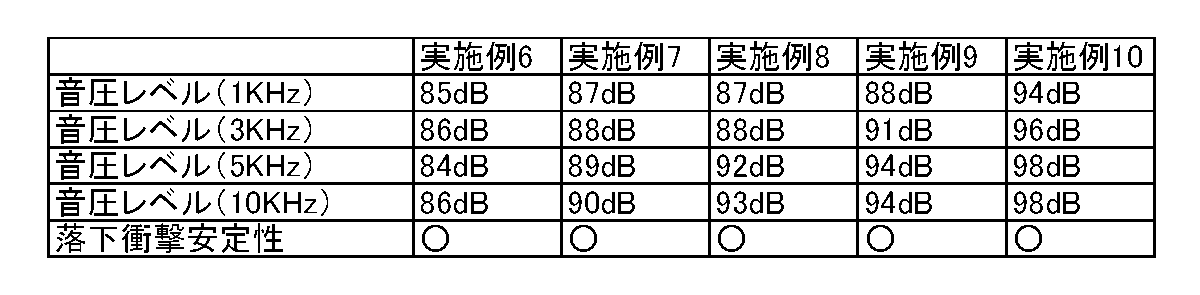
- experimental results of the electroacoustic transducers 100 to 500 of the respective embodiments will be exemplified as Examples 1 to 5 below.
- the electroacoustic transducer 600 that is the oscillation device of the present embodiment differs from the electroacoustic transducer 100 of the first embodiment in the following points.
- the elastic vibration area 112 is divided into two concentric circles in the radial direction by a circular slit 111. Each divided region is supported by a center support shaft 131 and an annular support 132.
- the piezoelectric vibrator 120 is attached to each of the divided elastic vibration areas 112, the number of the section vibrators 113 is doubled. For this reason, a higher sound pressure than the electroacoustic transducer 100 of the first embodiment can be oscillated.
- the electroacoustic transducer 100 can be prevented from being enlarged, and the acoustic characteristics are improved.
- a seventh embodiment of the present invention will be described below with reference to FIG.
- the electroacoustic transducer 700 which is the oscillation device of the present embodiment
- a large-diameter annular support 132 is disposed on the outer periphery of the electroacoustic transducer 600 of the sixth embodiment described above. .
- the elastic vibration area 112 is concentrically divided into three or more, for example, four by a plurality of circular slits 111 having different diameters. These divided elastic vibration areas 112 are respectively supported by inner and outer annular supports 132.
- the piezoelectric vibrator 120 is attached to each of the elastic vibration areas 112 that are divided into three or more in the radial direction as described above. For this reason, since the number of the segmented vibrators 113 is further increased from the electroacoustic transducer 600 according to the sixth embodiment, a higher sound pressure can be oscillated.
- the electroacoustic transducer 100 can be prevented from being enlarged, and the acoustic characteristics are improved.
- the rectangular elastic diaphragm 810 is divided into a plurality of rectangular elastic vibration areas 812 by a plurality of L-shaped slits 811.
- Piezoelectric vibrators 120 are attached to the plurality of elastic vibration zones 812 of the elastic diaphragm 810, respectively. Thus, a plurality of rectangular segmented vibrators 813 are formed in a matrix. In the electroacoustic transducer 800 of this embodiment, since the plurality of segmented vibrators 813 arranged in a matrix form oscillate as described above, a high-output sound pressure can be oscillated.
- the electroacoustic transducer 100 can be prevented from being enlarged, and the acoustic characteristics are improved.
- a ninth embodiment of the present invention will be described below with reference to FIG.
- a rectangular elastic diaphragm 910 is divided into a plurality of rectangular elastic vibration areas 912 by a plurality of U-shaped slits 911.
- a plurality of U-shaped slits 911 are connected in a shape that shares adjacent sides.
- a plurality of piezoelectric vibrators 120 are individually attached to a plurality of elastic vibration areas 912 of the elastic diaphragm 910, and a plurality of rectangular segmented vibrators 913 are formed in a matrix.
- a high output sound pressure can be oscillated.
- the electroacoustic transducer 100 can be prevented from being enlarged, and the acoustic characteristics are improved.
- the present invention is not limited to the present embodiment, and various modifications are allowed without departing from the scope of the present invention.
- the plurality of elastic vibration areas 112 are formed in the same shape and the same size.
- the shape and size of the plurality of elastic vibration areas 112 may be different (not shown).
- each part is formed double with respect to the electroacoustic transducer 600.
- FIG. it may be formed more than triple (not shown).
- the plurality of piezoelectric vibrators 120 have the same structure and the same shape and the same size. However, the structure, shape and size may be different (not shown).
- a mobile phone that outputs sound by the electroacoustic transducer 100 or the like is illustrated as an electric device.
- the electronic apparatus includes an electroacoustic transducer 100 that is an oscillation device, an ultrasonic detection unit that detects ultrasonic waves that are oscillated from the electroacoustic transducer 100 and reflected by the measurement object, and the detected ultrasonic wave.
- a sonar (not shown) having a distance measuring unit that calculates a distance from a sound wave to a measurement object may be used.
Abstract
Description
f=1/(2πL√(mC))
なお、"m"は質量、"C"はコンプライアンス、である。
本発明の実施の第二の形態を、図10を参照して以下に説明する。なお、以下に例示する本発明の実施の形態では、上述した第一の形態と同一の部分に関しては説明を省略する。
本発明の実施の第三の形態を、図11を参照して以下に説明する。本実施の形態の発振装置である電気音響変換器300では、実施の第一の形態の電気音響変換器100に対して、弾性振動区域112を二個の圧電振動子120で拘束している点が異なる。
本発明の実施の第四の形態について図12を参照して説明する。本実施の形態の電気音響変換器は、積層型の圧電振動子400を有する。図示されるように、圧電振動子400は、圧電層13からなる圧電層13a~13eが五層に積層された多層構造である。
本発明の実施の第五の形態について、図13を参照して説明する。本実施の形態の電気音響変換器500では、複数の区分振動子113が蓋510と仕切り板511により各々隔絶されていることが特徴である。

本発明の実施の第六の形態を、図14を参照して以下に説明する。本実施の形態の発振装置である電気音響変換器600では、実施の第一の形態の電気音響変換器100とは以下の点で異なる。まず、弾性振動区域112が円状のスリット111により、径方向に同心円状に二分割されている。そして分割後の各領域は、それぞれ中心支持軸131と円環支持体132とで支持されている。
本発明の実施の第七の形態を、図15を参照して以下に説明する。本実施の形態の発振装置である電気音響変換器700では、上述の実施の第六の形態の電気音響変換器600に対して、さらに外周に大径の円環支持体132が配置されている。
本発明の実施の第八の形態を、図16を参照して以下に説明する。本実施の形態の発振装置である電気音響変換器800では、矩形の弾性振動板810が、複数のL字型のスリット811によって複数の矩形の弾性振動区域812に区分されている。
本発明の実施の第九の形態を、図17を参照して以下に説明する。本実施の形態の発振装置である電気音響変換器900では、矩形の弾性振動板910が複数のコ字型のスリット911によって複数の矩形の弾性振動区域912に区分されている。ただし、本実施の形態の電気音響変換器900では、複数のコ字型のスリット911が、隣接する側辺を共有する形状に連結されている。
Claims (10)
- スリットで複数の弾性振動区域に区分されている弾性振動板と、
複数の前記弾性振動区域を前記スリットではない位置で支持している支持部材と、
前記支持部材で支持されている複数の前記弾性振動区域の少なくとも一部に個々に装着されていて電界の印加により伸縮振動する複数の圧電振動子と、
を有する発振装置。 - 前記弾性振動板は、放射状の複数の前記スリットで複数の前記弾性振動区域に区分されている請求項1に記載の発振装置。
- 複数の前記弾性振動区域が中心で支持されている請求項2に記載の発振装置。
- 前記弾性振動板が円形に形成されている請求項2または3に記載の発振装置。
- 前記弾性振動板は、L字型またはコ字型の複数の前記スリットで矩形の複数の前記弾性振動区域に区分されている請求項1に記載の発振装置。
- 前記弾性振動板が矩形に形成されている請求項5に記載の発振装置。
- 複数の前記弾性振動区域が同一形状に形成されている請求項1ないし6の何れか一項に記載の発振装置。
- 複数の前記弾性振動区域に装着されている複数の前記圧電振動子が同一形状に形成されている請求項1ないし7の何れか一項に記載の発振装置。
- 請求項1ないし8の何れか一項に記載の発振装置と、
前記発振装置に可聴域の音波を出力させる発振駆動部と、
を有する電子機器。 - 請求項1ないし8の何れか一項に記載の発振装置と、
前記発振装置から発振されて測定対象物で反射した前記超音波を検知する超音波検知部と、
検知された前記超音波から前記測定対象物までの距離を算出する測距部と、
を有する電子機器。
Priority Applications (4)
| Application Number | Priority Date | Filing Date | Title |
|---|---|---|---|
| CN201180033997.5A CN102986249B (zh) | 2010-07-23 | 2011-07-14 | 振荡器和电子设备 |
| JP2012525314A JP5761192B2 (ja) | 2010-07-23 | 2011-07-14 | 発振装置および電子機器 |
| US13/703,718 US8891333B2 (en) | 2010-07-23 | 2011-07-14 | Oscillator and electronic device |
| EP11809432.5A EP2597894A4 (en) | 2010-07-23 | 2011-07-14 | VIBRATION DEVICE AND ELECTRONIC DEVICE |
Applications Claiming Priority (2)
| Application Number | Priority Date | Filing Date | Title |
|---|---|---|---|
| JP2010-166549 | 2010-07-23 | ||
| JP2010166549 | 2010-07-23 |
Publications (1)
| Publication Number | Publication Date |
|---|---|
| WO2012011256A1 true WO2012011256A1 (ja) | 2012-01-26 |
Family
ID=45496689
Family Applications (1)
| Application Number | Title | Priority Date | Filing Date |
|---|---|---|---|
| PCT/JP2011/004035 WO2012011256A1 (ja) | 2010-07-23 | 2011-07-14 | 発振装置および電子機器 |
Country Status (5)
| Country | Link |
|---|---|
| US (1) | US8891333B2 (ja) |
| EP (1) | EP2597894A4 (ja) |
| JP (1) | JP5761192B2 (ja) |
| CN (1) | CN102986249B (ja) |
| WO (1) | WO2012011256A1 (ja) |
Cited By (6)
| Publication number | Priority date | Publication date | Assignee | Title |
|---|---|---|---|---|
| US20130083630A1 (en) * | 2010-07-23 | 2013-04-04 | Nec Corporation | Oscillator and electronic device |
| JPWO2015064081A1 (ja) * | 2013-10-31 | 2017-03-09 | パナソニック インテレクチュアル プロパティ コーポレーション オブ アメリカPanasonic Intellectual Property Corporation of America | 送信方法 |
| CN110602616A (zh) * | 2019-08-28 | 2019-12-20 | 武汉大学 | 一种高灵敏度mems压电式麦克风 |
| JP2021517396A (ja) * | 2018-03-05 | 2021-07-15 | グーグル エルエルシーGoogle LLC | パターン電極を含む分散モードラウドスピーカアクチュエータの駆動 |
| JPWO2022176002A1 (ja) * | 2021-02-16 | 2022-08-25 | ||
| US11902740B2 (en) | 2019-08-28 | 2024-02-13 | Wuhan Memsonics Technologies Co., Ltd. | High-sensitivity piezoelectric microphone |
Families Citing this family (17)
| Publication number | Priority date | Publication date | Assignee | Title |
|---|---|---|---|---|
| JP6180211B2 (ja) * | 2013-07-12 | 2017-08-16 | 富士フイルム株式会社 | ダイアフラム型共振memsデバイス用基板、ダイアフラム型共振memsデバイス及びその製造方法 |
| KR101480938B1 (ko) * | 2014-12-04 | 2015-01-14 | 범진시엔엘 주식회사 | 압전 스피커 |
| JP6761277B2 (ja) | 2016-05-13 | 2020-09-23 | 株式会社東芝 | スピーカシステム |
| CN106028228B (zh) * | 2016-07-25 | 2021-06-11 | 山东共达电声股份有限公司 | 一种振膜及具有该振膜的音响设备 |
| DE102017200111B3 (de) * | 2017-01-05 | 2018-03-15 | Robert Bosch Gmbh | Mikromechanische Schallwandleranordnung und entsprechendes Herstellungsverfahren |
| KR101890761B1 (ko) * | 2018-03-08 | 2018-08-22 | 범진시엔엘 주식회사 | 디스플레이 패널 스피커 |
| CN109587612A (zh) * | 2018-12-31 | 2019-04-05 | 瑞声声学科技(深圳)有限公司 | 压电式麦克风 |
| CN109737992B (zh) * | 2019-01-09 | 2020-11-06 | 苏州星航综测科技有限公司 | 一种具有周期性带隙结构的传感器结构 |
| US10924866B2 (en) * | 2019-02-27 | 2021-02-16 | Nokia Technologies Oy | Piezoelectric speaker |
| CN110545514B (zh) * | 2019-08-16 | 2021-01-08 | 瑞声声学科技(深圳)有限公司 | 压电式mems麦克风 |
| CN110545511B (zh) * | 2019-08-16 | 2021-05-07 | 瑞声声学科技(深圳)有限公司 | 压电式mems麦克风 |
| CN111225330A (zh) * | 2019-12-31 | 2020-06-02 | 瑞声科技(南京)有限公司 | 压电mems麦克风及压电mems麦克风的制备方法 |
| CN111147998B (zh) * | 2020-04-08 | 2020-07-31 | 共达电声股份有限公司 | Mems微型扬声器、mems微型扬声器的制备方法及电子设备 |
| CN111453691B (zh) * | 2020-04-21 | 2023-05-12 | 安徽奥飞声学科技有限公司 | 一种mems结构的制造方法 |
| JP2022125545A (ja) | 2021-02-17 | 2022-08-29 | 株式会社リコー | 音響変換器 |
| CN114339552A (zh) * | 2021-12-31 | 2022-04-12 | 瑞声开泰科技(武汉)有限公司 | 一种发声装置 |
| DE102022210125A1 (de) | 2022-09-26 | 2024-03-28 | Robert Bosch Gesellschaft mit beschränkter Haftung | Mikromechanische Schallwandlervorrichtung und entsprechendes Schallwandlungsverfahren |
Citations (7)
| Publication number | Priority date | Publication date | Assignee | Title |
|---|---|---|---|---|
| JPS59144997U (ja) * | 1983-03-18 | 1984-09-27 | 三洋電機株式会社 | 圧電型発音体 |
| JPH02141098A (ja) * | 1988-11-21 | 1990-05-30 | Murata Mfg Co Ltd | 圧電スピーカ |
| JPH03270282A (ja) | 1990-03-20 | 1991-12-02 | Matsushita Electric Ind Co Ltd | 複合圧電体 |
| JP2001016692A (ja) * | 1998-11-05 | 2001-01-19 | Matsushita Electric Ind Co Ltd | 圧電スピーカ、その製造方法およびスピーカシステム |
| JP2006211413A (ja) * | 2005-01-28 | 2006-08-10 | Taiyo Yuden Co Ltd | 圧電振動板 |
| WO2007026736A1 (ja) | 2005-08-31 | 2007-03-08 | Nec Corporation | 圧電アクチュエータ、音響素子、及び電子機器 |
| WO2007083497A1 (ja) | 2005-12-27 | 2007-07-26 | Nec Corporation | 圧電アクチュエータおよび電子機器 |
Family Cites Families (10)
| Publication number | Priority date | Publication date | Assignee | Title |
|---|---|---|---|---|
| JP2549673B2 (ja) * | 1987-09-30 | 1996-10-30 | 株式会社東芝 | 超音波治療用アプリケータ |
| WO1991015090A1 (fr) * | 1990-03-20 | 1991-10-03 | Matsushita Electric Industrial Co., Ltd. | Sonde ultrasonique |
| WO1998028942A1 (en) * | 1996-12-20 | 1998-07-02 | Nct Group, Inc. | Electroacoustic transducers comprising vibrating panels |
| KR100385388B1 (ko) | 1998-11-05 | 2003-05-27 | 마쯔시다덴기산교 가부시키가이샤 | 압전 스피커, 이의 제조 방법 및 이를 구비한 스피커 시스템 |
| JP2002135893A (ja) * | 2000-10-24 | 2002-05-10 | Matsushita Electric Ind Co Ltd | 圧電スピーカ及びその駆動回路 |
| JP3799001B2 (ja) * | 2001-09-10 | 2006-07-19 | 富士彦 小林 | 圧電スピーカ |
| JPWO2005006809A1 (ja) | 2003-07-09 | 2006-08-31 | 株式会社シマダ製作所 | 圧電型振動発生器及びこれを用いた振動送音器 |
| WO2009093291A1 (ja) * | 2008-01-21 | 2009-07-30 | Fujihiko Kobayashi | 圧電振動板 |
| US7804742B2 (en) * | 2008-01-29 | 2010-09-28 | Hyde Park Electronics Llc | Ultrasonic transducer for a proximity sensor |
| EP2597894A4 (en) * | 2010-07-23 | 2015-11-11 | Nec Corp | VIBRATION DEVICE AND ELECTRONIC DEVICE |
-
2011
- 2011-07-14 EP EP11809432.5A patent/EP2597894A4/en not_active Withdrawn
- 2011-07-14 WO PCT/JP2011/004035 patent/WO2012011256A1/ja active Application Filing
- 2011-07-14 US US13/703,718 patent/US8891333B2/en not_active Expired - Fee Related
- 2011-07-14 JP JP2012525314A patent/JP5761192B2/ja not_active Expired - Fee Related
- 2011-07-14 CN CN201180033997.5A patent/CN102986249B/zh not_active Expired - Fee Related
Patent Citations (7)
| Publication number | Priority date | Publication date | Assignee | Title |
|---|---|---|---|---|
| JPS59144997U (ja) * | 1983-03-18 | 1984-09-27 | 三洋電機株式会社 | 圧電型発音体 |
| JPH02141098A (ja) * | 1988-11-21 | 1990-05-30 | Murata Mfg Co Ltd | 圧電スピーカ |
| JPH03270282A (ja) | 1990-03-20 | 1991-12-02 | Matsushita Electric Ind Co Ltd | 複合圧電体 |
| JP2001016692A (ja) * | 1998-11-05 | 2001-01-19 | Matsushita Electric Ind Co Ltd | 圧電スピーカ、その製造方法およびスピーカシステム |
| JP2006211413A (ja) * | 2005-01-28 | 2006-08-10 | Taiyo Yuden Co Ltd | 圧電振動板 |
| WO2007026736A1 (ja) | 2005-08-31 | 2007-03-08 | Nec Corporation | 圧電アクチュエータ、音響素子、及び電子機器 |
| WO2007083497A1 (ja) | 2005-12-27 | 2007-07-26 | Nec Corporation | 圧電アクチュエータおよび電子機器 |
Non-Patent Citations (1)
| Title |
|---|
| See also references of EP2597894A4 |
Cited By (19)
| Publication number | Priority date | Publication date | Assignee | Title |
|---|---|---|---|---|
| US20130083630A1 (en) * | 2010-07-23 | 2013-04-04 | Nec Corporation | Oscillator and electronic device |
| US8891333B2 (en) * | 2010-07-23 | 2014-11-18 | Nec Corporation | Oscillator and electronic device |
| US10791011B2 (en) | 2013-10-31 | 2020-09-29 | Panasonic Intellectual Property Corporation Of America | Transmission method, transmission device, reception method and reception device |
| US11177991B2 (en) | 2013-10-31 | 2021-11-16 | Panasonic Intellectual Property Corporation Of America | Transmission method, transmission device, reception method and reception device |
| US10355898B2 (en) | 2013-10-31 | 2019-07-16 | Panasonic Intellectual Property Corporation Of America | Transmission method, transmission device, reception method and reception device |
| US10498575B2 (en) | 2013-10-31 | 2019-12-03 | Panasonic Intellectual Property Corporation Of America | Transmission method, transmission device, reception method and reception device |
| US11902067B2 (en) | 2013-10-31 | 2024-02-13 | Panasonic Intellectual Property Corporation Of America | Transmission method, transmission device, reception method and reception device |
| US10608855B2 (en) | 2013-10-31 | 2020-03-31 | Panasonic Intellectual Property Corporation Of America | Transmission method, transmission device, reception method and reception device |
| JPWO2015064081A1 (ja) * | 2013-10-31 | 2017-03-09 | パナソニック インテレクチュアル プロパティ コーポレーション オブ アメリカPanasonic Intellectual Property Corporation of America | 送信方法 |
| US10911278B2 (en) | 2013-10-31 | 2021-02-02 | Panasonic Intellectual Property Corporation Of America | Transmission method, transmission device, reception method and reception device |
| US11575553B2 (en) | 2013-10-31 | 2023-02-07 | Panasonic Intellectual Property Corporation Of America | Transmission method, transmission device, reception method and reception device |
| US10129062B2 (en) | 2013-10-31 | 2018-11-13 | Panasonic Intellectual Property Corporation Of America | Transmission method, transmission device, reception method and reception device |
| JP7195330B2 (ja) | 2018-03-05 | 2022-12-23 | グーグル エルエルシー | パターン電極を含む分散モードラウドスピーカアクチュエータの駆動 |
| JP2021517396A (ja) * | 2018-03-05 | 2021-07-15 | グーグル エルエルシーGoogle LLC | パターン電極を含む分散モードラウドスピーカアクチュエータの駆動 |
| CN110602616A (zh) * | 2019-08-28 | 2019-12-20 | 武汉大学 | 一种高灵敏度mems压电式麦克风 |
| US11902740B2 (en) | 2019-08-28 | 2024-02-13 | Wuhan Memsonics Technologies Co., Ltd. | High-sensitivity piezoelectric microphone |
| JPWO2022176002A1 (ja) * | 2021-02-16 | 2022-08-25 | ||
| WO2022176002A1 (ja) * | 2021-02-16 | 2022-08-25 | 本多電子株式会社 | 計測機器用の超音波振動子 |
| JP7294701B2 (ja) | 2021-02-16 | 2023-06-20 | 本多電子株式会社 | 計測機器用の超音波振動子 |
Also Published As
| Publication number | Publication date |
|---|---|
| US20130083630A1 (en) | 2013-04-04 |
| JP5761192B2 (ja) | 2015-08-12 |
| CN102986249A (zh) | 2013-03-20 |
| US8891333B2 (en) | 2014-11-18 |
| JPWO2012011256A1 (ja) | 2013-09-09 |
| CN102986249B (zh) | 2015-08-12 |
| EP2597894A1 (en) | 2013-05-29 |
| EP2597894A4 (en) | 2015-11-11 |
Similar Documents
| Publication | Publication Date | Title |
|---|---|---|
| JP5761192B2 (ja) | 発振装置および電子機器 | |
| JP5682973B2 (ja) | 発振装置および電子機器 | |
| JP5741580B2 (ja) | 発振装置 | |
| JP5652813B2 (ja) | 電気音響変換器及びそれを用いた電子機器 | |
| JP5939160B2 (ja) | 発振装置および電子機器 | |
| JP2012015755A (ja) | 発振装置および電子機器 | |
| JP5803917B2 (ja) | 発振装置および電子機器 | |
| JP2012015758A (ja) | 発振装置、その製造方法、電子機器 | |
| JP5771952B2 (ja) | 発振装置および電子機器 | |
| JP5527083B2 (ja) | 発振装置 | |
| EP2590435A1 (en) | Vibration device | |
| JP5617412B2 (ja) | 発振装置および電子機器 | |
| JP2012015757A (ja) | 発振装置および電子機器 | |
| JP2012029104A (ja) | 発振装置および電子機器 | |
| JP5750865B2 (ja) | 発振装置および電子機器 | |
| JP5505165B2 (ja) | 発振装置 | |
| JP2012029078A (ja) | 発振装置 | |
| JP2012029105A (ja) | 発振装置 | |
| JP2012029108A (ja) | 発振装置および電子機器 | |
| JP5659598B2 (ja) | 発振装置 | |
| JP2012134595A (ja) | 発振装置および電子機器 | |
| JP2012134599A (ja) | 発振装置および電子機器 | |
| JP2012134597A (ja) | 発振装置および電子機器 | |
| JP2012029098A (ja) | 発振装置および電子機器 | |
| JP2012015759A (ja) | 発振装置および電子機器 |
Legal Events
| Date | Code | Title | Description |
|---|---|---|---|
| WWE | Wipo information: entry into national phase |
Ref document number: 201180033997.5 Country of ref document: CN |
|
| 121 | Ep: the epo has been informed by wipo that ep was designated in this application |
Ref document number: 11809432 Country of ref document: EP Kind code of ref document: A1 |
|
| REEP | Request for entry into the european phase |
Ref document number: 2011809432 Country of ref document: EP |
|
| WWE | Wipo information: entry into national phase |
Ref document number: 2011809432 Country of ref document: EP |
|
| WWE | Wipo information: entry into national phase |
Ref document number: 2012525314 Country of ref document: JP |
|
| WWE | Wipo information: entry into national phase |
Ref document number: 13703718 Country of ref document: US |
|
| NENP | Non-entry into the national phase |
Ref country code: DE |