WO2012011176A1 - Véhicule entraîné électriquement et son procédé de commande de chargement - Google Patents
Véhicule entraîné électriquement et son procédé de commande de chargement Download PDFInfo
- Publication number
- WO2012011176A1 WO2012011176A1 PCT/JP2010/062322 JP2010062322W WO2012011176A1 WO 2012011176 A1 WO2012011176 A1 WO 2012011176A1 JP 2010062322 W JP2010062322 W JP 2010062322W WO 2012011176 A1 WO2012011176 A1 WO 2012011176A1
- Authority
- WO
- WIPO (PCT)
- Prior art keywords
- power
- conversion path
- charging
- switch
- storage device
- Prior art date
Links
Images


Classifications
-
- H—ELECTRICITY
- H02—GENERATION; CONVERSION OR DISTRIBUTION OF ELECTRIC POWER
- H02J—CIRCUIT ARRANGEMENTS OR SYSTEMS FOR SUPPLYING OR DISTRIBUTING ELECTRIC POWER; SYSTEMS FOR STORING ELECTRIC ENERGY
- H02J7/00—Circuit arrangements for charging or depolarising batteries or for supplying loads from batteries
- H02J7/02—Circuit arrangements for charging or depolarising batteries or for supplying loads from batteries for charging batteries from ac mains by converters
-
- B—PERFORMING OPERATIONS; TRANSPORTING
- B60—VEHICLES IN GENERAL
- B60L—PROPULSION OF ELECTRICALLY-PROPELLED VEHICLES; SUPPLYING ELECTRIC POWER FOR AUXILIARY EQUIPMENT OF ELECTRICALLY-PROPELLED VEHICLES; ELECTRODYNAMIC BRAKE SYSTEMS FOR VEHICLES IN GENERAL; MAGNETIC SUSPENSION OR LEVITATION FOR VEHICLES; MONITORING OPERATING VARIABLES OF ELECTRICALLY-PROPELLED VEHICLES; ELECTRIC SAFETY DEVICES FOR ELECTRICALLY-PROPELLED VEHICLES
- B60L1/00—Supplying electric power to auxiliary equipment of vehicles
- B60L1/003—Supplying electric power to auxiliary equipment of vehicles to auxiliary motors, e.g. for pumps, compressors
-
- B—PERFORMING OPERATIONS; TRANSPORTING
- B60—VEHICLES IN GENERAL
- B60L—PROPULSION OF ELECTRICALLY-PROPELLED VEHICLES; SUPPLYING ELECTRIC POWER FOR AUXILIARY EQUIPMENT OF ELECTRICALLY-PROPELLED VEHICLES; ELECTRODYNAMIC BRAKE SYSTEMS FOR VEHICLES IN GENERAL; MAGNETIC SUSPENSION OR LEVITATION FOR VEHICLES; MONITORING OPERATING VARIABLES OF ELECTRICALLY-PROPELLED VEHICLES; ELECTRIC SAFETY DEVICES FOR ELECTRICALLY-PROPELLED VEHICLES
- B60L3/00—Electric devices on electrically-propelled vehicles for safety purposes; Monitoring operating variables, e.g. speed, deceleration or energy consumption
- B60L3/0023—Detecting, eliminating, remedying or compensating for drive train abnormalities, e.g. failures within the drive train
- B60L3/0069—Detecting, eliminating, remedying or compensating for drive train abnormalities, e.g. failures within the drive train relating to the isolation, e.g. ground fault or leak current
-
- B—PERFORMING OPERATIONS; TRANSPORTING
- B60—VEHICLES IN GENERAL
- B60L—PROPULSION OF ELECTRICALLY-PROPELLED VEHICLES; SUPPLYING ELECTRIC POWER FOR AUXILIARY EQUIPMENT OF ELECTRICALLY-PROPELLED VEHICLES; ELECTRODYNAMIC BRAKE SYSTEMS FOR VEHICLES IN GENERAL; MAGNETIC SUSPENSION OR LEVITATION FOR VEHICLES; MONITORING OPERATING VARIABLES OF ELECTRICALLY-PROPELLED VEHICLES; ELECTRIC SAFETY DEVICES FOR ELECTRICALLY-PROPELLED VEHICLES
- B60L3/00—Electric devices on electrically-propelled vehicles for safety purposes; Monitoring operating variables, e.g. speed, deceleration or energy consumption
- B60L3/04—Cutting off the power supply under fault conditions
-
- B—PERFORMING OPERATIONS; TRANSPORTING
- B60—VEHICLES IN GENERAL
- B60L—PROPULSION OF ELECTRICALLY-PROPELLED VEHICLES; SUPPLYING ELECTRIC POWER FOR AUXILIARY EQUIPMENT OF ELECTRICALLY-PROPELLED VEHICLES; ELECTRODYNAMIC BRAKE SYSTEMS FOR VEHICLES IN GENERAL; MAGNETIC SUSPENSION OR LEVITATION FOR VEHICLES; MONITORING OPERATING VARIABLES OF ELECTRICALLY-PROPELLED VEHICLES; ELECTRIC SAFETY DEVICES FOR ELECTRICALLY-PROPELLED VEHICLES
- B60L53/00—Methods of charging batteries, specially adapted for electric vehicles; Charging stations or on-board charging equipment therefor; Exchange of energy storage elements in electric vehicles
- B60L53/10—Methods of charging batteries, specially adapted for electric vehicles; Charging stations or on-board charging equipment therefor; Exchange of energy storage elements in electric vehicles characterised by the energy transfer between the charging station and the vehicle
- B60L53/14—Conductive energy transfer
-
- B—PERFORMING OPERATIONS; TRANSPORTING
- B60—VEHICLES IN GENERAL
- B60L—PROPULSION OF ELECTRICALLY-PROPELLED VEHICLES; SUPPLYING ELECTRIC POWER FOR AUXILIARY EQUIPMENT OF ELECTRICALLY-PROPELLED VEHICLES; ELECTRODYNAMIC BRAKE SYSTEMS FOR VEHICLES IN GENERAL; MAGNETIC SUSPENSION OR LEVITATION FOR VEHICLES; MONITORING OPERATING VARIABLES OF ELECTRICALLY-PROPELLED VEHICLES; ELECTRIC SAFETY DEVICES FOR ELECTRICALLY-PROPELLED VEHICLES
- B60L53/00—Methods of charging batteries, specially adapted for electric vehicles; Charging stations or on-board charging equipment therefor; Exchange of energy storage elements in electric vehicles
- B60L53/20—Methods of charging batteries, specially adapted for electric vehicles; Charging stations or on-board charging equipment therefor; Exchange of energy storage elements in electric vehicles characterised by converters located in the vehicle
- B60L53/22—Constructional details or arrangements of charging converters specially adapted for charging electric vehicles
-
- H—ELECTRICITY
- H02—GENERATION; CONVERSION OR DISTRIBUTION OF ELECTRIC POWER
- H02M—APPARATUS FOR CONVERSION BETWEEN AC AND AC, BETWEEN AC AND DC, OR BETWEEN DC AND DC, AND FOR USE WITH MAINS OR SIMILAR POWER SUPPLY SYSTEMS; CONVERSION OF DC OR AC INPUT POWER INTO SURGE OUTPUT POWER; CONTROL OR REGULATION THEREOF
- H02M1/00—Details of apparatus for conversion
- H02M1/42—Circuits or arrangements for compensating for or adjusting power factor in converters or inverters
- H02M1/4208—Arrangements for improving power factor of AC input
- H02M1/4225—Arrangements for improving power factor of AC input using a non-isolated boost converter
-
- H—ELECTRICITY
- H02—GENERATION; CONVERSION OR DISTRIBUTION OF ELECTRIC POWER
- H02M—APPARATUS FOR CONVERSION BETWEEN AC AND AC, BETWEEN AC AND DC, OR BETWEEN DC AND DC, AND FOR USE WITH MAINS OR SIMILAR POWER SUPPLY SYSTEMS; CONVERSION OF DC OR AC INPUT POWER INTO SURGE OUTPUT POWER; CONTROL OR REGULATION THEREOF
- H02M3/00—Conversion of dc power input into dc power output
- H02M3/02—Conversion of dc power input into dc power output without intermediate conversion into ac
- H02M3/04—Conversion of dc power input into dc power output without intermediate conversion into ac by static converters
- H02M3/10—Conversion of dc power input into dc power output without intermediate conversion into ac by static converters using discharge tubes with control electrode or semiconductor devices with control electrode
- H02M3/145—Conversion of dc power input into dc power output without intermediate conversion into ac by static converters using discharge tubes with control electrode or semiconductor devices with control electrode using devices of a triode or transistor type requiring continuous application of a control signal
- H02M3/155—Conversion of dc power input into dc power output without intermediate conversion into ac by static converters using discharge tubes with control electrode or semiconductor devices with control electrode using devices of a triode or transistor type requiring continuous application of a control signal using semiconductor devices only
- H02M3/156—Conversion of dc power input into dc power output without intermediate conversion into ac by static converters using discharge tubes with control electrode or semiconductor devices with control electrode using devices of a triode or transistor type requiring continuous application of a control signal using semiconductor devices only with automatic control of output voltage or current, e.g. switching regulators
- H02M3/158—Conversion of dc power input into dc power output without intermediate conversion into ac by static converters using discharge tubes with control electrode or semiconductor devices with control electrode using devices of a triode or transistor type requiring continuous application of a control signal using semiconductor devices only with automatic control of output voltage or current, e.g. switching regulators including plural semiconductor devices as final control devices for a single load
-
- B—PERFORMING OPERATIONS; TRANSPORTING
- B60—VEHICLES IN GENERAL
- B60L—PROPULSION OF ELECTRICALLY-PROPELLED VEHICLES; SUPPLYING ELECTRIC POWER FOR AUXILIARY EQUIPMENT OF ELECTRICALLY-PROPELLED VEHICLES; ELECTRODYNAMIC BRAKE SYSTEMS FOR VEHICLES IN GENERAL; MAGNETIC SUSPENSION OR LEVITATION FOR VEHICLES; MONITORING OPERATING VARIABLES OF ELECTRICALLY-PROPELLED VEHICLES; ELECTRIC SAFETY DEVICES FOR ELECTRICALLY-PROPELLED VEHICLES
- B60L2210/00—Converter types
- B60L2210/10—DC to DC converters
-
- B—PERFORMING OPERATIONS; TRANSPORTING
- B60—VEHICLES IN GENERAL
- B60L—PROPULSION OF ELECTRICALLY-PROPELLED VEHICLES; SUPPLYING ELECTRIC POWER FOR AUXILIARY EQUIPMENT OF ELECTRICALLY-PROPELLED VEHICLES; ELECTRODYNAMIC BRAKE SYSTEMS FOR VEHICLES IN GENERAL; MAGNETIC SUSPENSION OR LEVITATION FOR VEHICLES; MONITORING OPERATING VARIABLES OF ELECTRICALLY-PROPELLED VEHICLES; ELECTRIC SAFETY DEVICES FOR ELECTRICALLY-PROPELLED VEHICLES
- B60L2210/00—Converter types
- B60L2210/30—AC to DC converters
-
- B—PERFORMING OPERATIONS; TRANSPORTING
- B60—VEHICLES IN GENERAL
- B60L—PROPULSION OF ELECTRICALLY-PROPELLED VEHICLES; SUPPLYING ELECTRIC POWER FOR AUXILIARY EQUIPMENT OF ELECTRICALLY-PROPELLED VEHICLES; ELECTRODYNAMIC BRAKE SYSTEMS FOR VEHICLES IN GENERAL; MAGNETIC SUSPENSION OR LEVITATION FOR VEHICLES; MONITORING OPERATING VARIABLES OF ELECTRICALLY-PROPELLED VEHICLES; ELECTRIC SAFETY DEVICES FOR ELECTRICALLY-PROPELLED VEHICLES
- B60L2210/00—Converter types
- B60L2210/40—DC to AC converters
- B60L2210/42—Voltage source inverters
-
- H—ELECTRICITY
- H02—GENERATION; CONVERSION OR DISTRIBUTION OF ELECTRIC POWER
- H02J—CIRCUIT ARRANGEMENTS OR SYSTEMS FOR SUPPLYING OR DISTRIBUTING ELECTRIC POWER; SYSTEMS FOR STORING ELECTRIC ENERGY
- H02J2207/00—Indexing scheme relating to details of circuit arrangements for charging or depolarising batteries or for supplying loads from batteries
- H02J2207/20—Charging or discharging characterised by the power electronics converter
-
- H—ELECTRICITY
- H02—GENERATION; CONVERSION OR DISTRIBUTION OF ELECTRIC POWER
- H02J—CIRCUIT ARRANGEMENTS OR SYSTEMS FOR SUPPLYING OR DISTRIBUTING ELECTRIC POWER; SYSTEMS FOR STORING ELECTRIC ENERGY
- H02J2207/00—Indexing scheme relating to details of circuit arrangements for charging or depolarising batteries or for supplying loads from batteries
- H02J2207/40—Indexing scheme relating to details of circuit arrangements for charging or depolarising batteries or for supplying loads from batteries adapted for charging from various sources, e.g. AC, DC or multivoltage
-
- Y—GENERAL TAGGING OF NEW TECHNOLOGICAL DEVELOPMENTS; GENERAL TAGGING OF CROSS-SECTIONAL TECHNOLOGIES SPANNING OVER SEVERAL SECTIONS OF THE IPC; TECHNICAL SUBJECTS COVERED BY FORMER USPC CROSS-REFERENCE ART COLLECTIONS [XRACs] AND DIGESTS
- Y02—TECHNOLOGIES OR APPLICATIONS FOR MITIGATION OR ADAPTATION AGAINST CLIMATE CHANGE
- Y02T—CLIMATE CHANGE MITIGATION TECHNOLOGIES RELATED TO TRANSPORTATION
- Y02T10/00—Road transport of goods or passengers
- Y02T10/60—Other road transportation technologies with climate change mitigation effect
- Y02T10/70—Energy storage systems for electromobility, e.g. batteries
-
- Y—GENERAL TAGGING OF NEW TECHNOLOGICAL DEVELOPMENTS; GENERAL TAGGING OF CROSS-SECTIONAL TECHNOLOGIES SPANNING OVER SEVERAL SECTIONS OF THE IPC; TECHNICAL SUBJECTS COVERED BY FORMER USPC CROSS-REFERENCE ART COLLECTIONS [XRACs] AND DIGESTS
- Y02—TECHNOLOGIES OR APPLICATIONS FOR MITIGATION OR ADAPTATION AGAINST CLIMATE CHANGE
- Y02T—CLIMATE CHANGE MITIGATION TECHNOLOGIES RELATED TO TRANSPORTATION
- Y02T10/00—Road transport of goods or passengers
- Y02T10/60—Other road transportation technologies with climate change mitigation effect
- Y02T10/7072—Electromobility specific charging systems or methods for batteries, ultracapacitors, supercapacitors or double-layer capacitors
-
- Y—GENERAL TAGGING OF NEW TECHNOLOGICAL DEVELOPMENTS; GENERAL TAGGING OF CROSS-SECTIONAL TECHNOLOGIES SPANNING OVER SEVERAL SECTIONS OF THE IPC; TECHNICAL SUBJECTS COVERED BY FORMER USPC CROSS-REFERENCE ART COLLECTIONS [XRACs] AND DIGESTS
- Y02—TECHNOLOGIES OR APPLICATIONS FOR MITIGATION OR ADAPTATION AGAINST CLIMATE CHANGE
- Y02T—CLIMATE CHANGE MITIGATION TECHNOLOGIES RELATED TO TRANSPORTATION
- Y02T10/00—Road transport of goods or passengers
- Y02T10/60—Other road transportation technologies with climate change mitigation effect
- Y02T10/72—Electric energy management in electromobility
-
- Y—GENERAL TAGGING OF NEW TECHNOLOGICAL DEVELOPMENTS; GENERAL TAGGING OF CROSS-SECTIONAL TECHNOLOGIES SPANNING OVER SEVERAL SECTIONS OF THE IPC; TECHNICAL SUBJECTS COVERED BY FORMER USPC CROSS-REFERENCE ART COLLECTIONS [XRACs] AND DIGESTS
- Y02—TECHNOLOGIES OR APPLICATIONS FOR MITIGATION OR ADAPTATION AGAINST CLIMATE CHANGE
- Y02T—CLIMATE CHANGE MITIGATION TECHNOLOGIES RELATED TO TRANSPORTATION
- Y02T10/00—Road transport of goods or passengers
- Y02T10/80—Technologies aiming to reduce greenhouse gasses emissions common to all road transportation technologies
- Y02T10/92—Energy efficient charging or discharging systems for batteries, ultracapacitors, supercapacitors or double-layer capacitors specially adapted for vehicles
-
- Y—GENERAL TAGGING OF NEW TECHNOLOGICAL DEVELOPMENTS; GENERAL TAGGING OF CROSS-SECTIONAL TECHNOLOGIES SPANNING OVER SEVERAL SECTIONS OF THE IPC; TECHNICAL SUBJECTS COVERED BY FORMER USPC CROSS-REFERENCE ART COLLECTIONS [XRACs] AND DIGESTS
- Y02—TECHNOLOGIES OR APPLICATIONS FOR MITIGATION OR ADAPTATION AGAINST CLIMATE CHANGE
- Y02T—CLIMATE CHANGE MITIGATION TECHNOLOGIES RELATED TO TRANSPORTATION
- Y02T90/00—Enabling technologies or technologies with a potential or indirect contribution to GHG emissions mitigation
- Y02T90/10—Technologies relating to charging of electric vehicles
- Y02T90/12—Electric charging stations
-
- Y—GENERAL TAGGING OF NEW TECHNOLOGICAL DEVELOPMENTS; GENERAL TAGGING OF CROSS-SECTIONAL TECHNOLOGIES SPANNING OVER SEVERAL SECTIONS OF THE IPC; TECHNICAL SUBJECTS COVERED BY FORMER USPC CROSS-REFERENCE ART COLLECTIONS [XRACs] AND DIGESTS
- Y02—TECHNOLOGIES OR APPLICATIONS FOR MITIGATION OR ADAPTATION AGAINST CLIMATE CHANGE
- Y02T—CLIMATE CHANGE MITIGATION TECHNOLOGIES RELATED TO TRANSPORTATION
- Y02T90/00—Enabling technologies or technologies with a potential or indirect contribution to GHG emissions mitigation
- Y02T90/10—Technologies relating to charging of electric vehicles
- Y02T90/14—Plug-in electric vehicles
Definitions
- the present invention relates to an electric vehicle and a charging control method thereof, and more particularly to a charging system for an in-vehicle power storage device using a power source outside the vehicle and its control.
- the on-vehicle power storage is performed by a power source outside the vehicle (hereinafter also simply referred to as “external power source”)
- a power source outside the vehicle hereinafter also simply referred to as “external power source”.
- charging of the power storage device by the external power supply is also referred to as “external charging”.
- Patent Document 1 describes a configuration in which a vehicle-mounted battery is charged from a commercial power source via an insulating transformer.
- the battery charger is configured to share the inverter components that control the vehicle driving motor.
- Patent Document 2 describes a configuration including an insulating transformer 330 as a charger for charging an in-vehicle power storage device from an external power source.
- Patent Document 3 also describes a configuration for externally charging a main battery mounted on an electric vehicle with an external power source.
- Patent Document 3 shows a configuration in which an energization path for charging a main battery from an external power source and an energization path formed between the main battery and the vehicle drive motor during traveling are independent.
- Patent Documents 1 to 3 exemplify a configuration including an insulating transformer for a charger that converts electric power from an external power source into charging power for an in-vehicle power storage device.
- the charger is configured to include an insulation transformer, the in-vehicle electric device can be reliably insulated from the external power source.
- it is possible to ensure insulation between the external power supply and the in-vehicle electric device even when it is necessary to electrically connect the in-vehicle power storage device and the in-vehicle electric device by a relay during external charging. Is advantageous in terms of safety.
- the present invention has been made in order to solve such problems, and the object of the present invention is to provide external charging with insulation performance and efficiency when charging an in-vehicle power storage device with an external power source. It is an object of the present invention to provide an electric vehicle capable of selectively applying priority non-insulated external charging according to the situation.
- an electric vehicle in one aspect of the present invention, includes a power storage device for storing electric power input / output to / from the vehicle drive motor and a charger for charging the power storage device with an external power source.
- the charger is configured to electrically insulate between the external power source and the power storage device via the insulation mechanism and to convert the power from the external power source into the charging power of the power storage device, and to bypass the insulation mechanism
- the second power conversion path for electrically connecting the external power source and the power storage device to convert the power from the external power source into the charging power of the power storage device, and the first switch.
- the insulation mechanism is configured to transmit electrical energy after electrically insulating the primary side and the secondary side.
- the first switch is provided to selectively form one of the first power conversion path and the second power conversion path during external charging.
- the electric vehicle further includes an electric load that is operated by electric power of the power storage device, and a second switch connected between the power storage device and the electric load.
- the charger executes selection of the first power conversion path and the second power conversion path in response to turning on and off of the second switch.
- the charger selects the first power conversion path when the second switch is on, while selecting the second power conversion path when the second switch is off. Control the first switch.
- the insulation mechanism is constituted by an insulation transformer that transmits electric energy between the primary side and the secondary side by electromagnetic induction.
- the charger further includes a first power converter, a second power converter, a third power converter, and a smoothing inductor.
- the first power converter is configured to convert electric power from an external power source into a DC voltage and output it between the first power supply wiring and the first ground wiring.
- the second power converter is configured to convert a DC voltage into an AC voltage and output it to the primary side of the isolation transformer when the first power conversion path is selected.
- the third power converter converts the secondary side AC voltage of the insulating transformer into a charging voltage of the power storage device, and converts the second power supply wiring and the second ground wiring. It is configured to output in between.
- the smoothing inductor is connected between the second power supply wiring and the power storage device.
- Each of the second power converter and the third power converter includes a plurality of switching elements.
- the third power converter stops operating when the second power conversion path is selected.
- the second power converter converts the DC voltage from the first power converter into the charging voltage of the power storage device by using a part of the plurality of switching elements and the smoothing inductor. Operates to form an isolated chopper circuit.
- the first switch has a first switch element, a second switch element, and a third switch element.
- the first switching element is connected between the primary side of the insulating transformer and the second power supply wiring.
- the second switching element is connected between the first ground wiring and the second ground wiring.
- the third switching element is interposed and connected to the energization path on the primary side of the insulating transformer.
- the first switching element and the second switching element are turned off when the first power conversion path is selected, and are turned on when the second power conversion path is selected.
- the third open / close element is turned on when the first power conversion path is selected, and is turned off when the second power conversion path is selected.
- the first switch has a first switch element, a second switch element, and a third switch element.
- the first open / close element is connected between one wiring on the primary side of the insulating transformer and the second power supply wiring.
- the second switch element is connected between the other wiring on the primary side of the insulating transformer and the second ground wiring.
- the third switching element is interposed and connected to the energization path on the primary side of the insulating transformer.
- the first switching element and the second switching element are turned off when the first power conversion path is selected, and are turned on when the second power conversion path is selected.
- the third open / close element is turned on when the first power conversion path is selected, and is turned off when the second power conversion path is selected.
- the second power converter constitutes a non-insulated chopper circuit and operates to electrically connect the first ground wiring and the second ground wiring. To do.
- the charger further includes a first power converter, a second power converter, a third power converter, and a smoothing inductor.
- the first power converter is configured to convert electric power from an external power source into a DC voltage according to a voltage command value and output the DC voltage between the first power supply wiring and the first ground wiring.
- the second power converter includes a plurality of switching elements so as to convert a DC voltage into an AC voltage and output it to the primary side of the isolation transformer when the first power conversion path is selected.
- the third power converter converts the secondary side AC voltage of the insulating transformer into a charging voltage of the power storage device, and converts the second power supply wiring and the second ground wiring. It is configured to output in between.
- the smoothing inductor is connected between the second power supply wiring and the power storage device.
- the first switch is electrically connected between the first power supply wiring and the second power supply wiring and between the first ground wiring and the second ground wiring when the second power conversion path is selected. Connecting.
- the second power converter and the third power converter stop operating when the second power conversion path is selected.
- the voltage command value of the first power converter is set so as to correspond to the charging voltage of the power storage device when the second power conversion path is selected.
- the first switch has a first switch element and a second switch element.
- the first open / close element is connected between the first power supply wiring and the second power supply wiring, and is turned off when the first power conversion path is selected, while being turned on when the second power conversion path is selected.
- the second opening / closing element is connected between the first ground wiring and the second ground wiring, and is turned off when the first power conversion path is selected, while being turned on when the second power conversion path is selected.
- the insulating mechanism includes a capacitor, a third switch, and a fourth switch.
- the third switch is provided between the bipolar terminal of the capacitor and the primary side.
- the fourth switch is provided between the bipolar terminal of the capacitor and the secondary side.
- the charger further includes a first power converter.
- the first power converter is configured to convert electric power from an external power source into direct-current power for charging the power storage device, and output the DC power to the primary side of the insulating mechanism.
- the power storage device is electrically connected to the secondary side of the insulating mechanism during external charging.
- the first switch is disposed so as to bypass the third switch and the fourth switch and to electrically connect the primary side and the secondary side of the insulation mechanism.
- the first switch is controlled to be fixed off when the first power conversion path is selected, and to be fixed on when the second power conversion path is selected. Is done.
- the third switch is turned on and off alternately and complementarily with the fourth switch when the first power conversion path is selected, and is fixed off when the second power conversion path is selected.
- the fourth switch is turned on and off alternately and complementarily with the third switch when the first power conversion path is selected, and is fixed off when the second power conversion path is selected. To be controlled.
- the electric vehicle includes a power storage device for storing electric power input / output with respect to the vehicle driving motor, and an external power supply. And a charger for charging.
- the charger is configured such that the power conversion path from the external power source to the power storage device is switched by controlling the first switch.
- the control method includes a first charging mode for electrically insulating the external power source and the power storage device and charging the power storage device, and electrically connecting the external power source and the power storage device. Selecting one of the second charging modes for charging the power storage device by connecting to the battery and electrically insulating the primary side and the secondary side when the first charging mode is selected.
- the first switch is formed so as to form a first power conversion path for converting the electric power from the external power source into the charging power of the power storage device via the insulation mechanism configured to transmit electric energy at And when the second charging mode is selected, the second power conversion path is formed so as to bypass the insulation mechanism and convert the power from the external power source into the charging power of the power storage device when the second charging mode is selected.
- the electric vehicle further includes an electric load that is operated by electric power of the power storage device, and a second switch connected between the power storage device and the electric load.
- the step of selecting performs selection of 1st charge mode and 2nd charge mode corresponding to ON / OFF of a 2nd switch.
- the selecting step selects the first charging mode when the second switch is turned on, while selecting the second charging mode when the second switch is turned off.
- external charging when charging an in-vehicle power storage device of an electric vehicle using an external power source, external charging that ensures insulation performance and non-insulated external charging that prioritizes efficiency are selectively applied depending on the situation. be able to.
- FIG. 2 is a circuit diagram illustrating a configuration example of an AC-DC converter (PFC circuit) illustrated in FIG. 1.
- FIG. 3 is a waveform diagram for explaining the operation of the PFC circuit shown in FIG. 2.
- PFC circuit AC-DC converter
- FIG. 3 is a waveform diagram for explaining the operation of the PFC circuit shown in FIG. 2.
- 5 is a chart for illustrating an operation during external charging of a charger in the electric vehicle according to the first embodiment.
- It is a block diagram which shows the electric system structure of the electric vehicle by the modification of Embodiment 1 of this invention.
- It is a block diagram which shows the electric system structure of the electric vehicle by Embodiment 2 of this invention.
- FIG. 5 is a chart for explaining an operation at the time of external charging of a charger in an electric vehicle according to a second embodiment. It is a block diagram which shows the electric system structure of the electric vehicle by Embodiment 3 of this invention.
- FIG. 12 is a waveform diagram for explaining an operation during external charging of a charger in an electric vehicle according to a third embodiment.
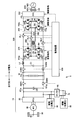
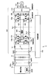
- FIG. 1 is a block diagram showing an electric system configuration of an electric vehicle according to Embodiment 1 of the present invention.
- the electric vehicle 5 includes a main battery 10, an electric load 15, system main relays SMR1 and SMR2, and a control device 100.
- Control device 100 indicates a functional part related to a control function at the time of external charging related to the present embodiment, among the functions for controlling equipment mounted on electric vehicle 5.
- the control device 100 can be configured to achieve the above functions by predetermined arithmetic processing by executing a program stored in an internal memory (not shown) or by predetermined arithmetic processing by hardware such as an electronic circuit.
- the main battery 10 is shown as a representative example of the “power storage device”, and typically includes a secondary battery such as a lithium ion battery or a nickel metal hydride battery.
- a secondary battery such as a lithium ion battery or a nickel metal hydride battery.
- the output voltage of the main battery 10 is about 200V.
- the “power storage device” may be configured by an electric double layer capacitor or a combination of a secondary battery and a capacitor.
- the electric load 15 comprehensively indicates an electric device group that operates by the electric power of the main battery 10.
- the electric load 15 includes a power control unit (PCU) 20, a motor generator 30, a DCDC converter 60, an auxiliary battery 70, a low voltage auxiliary machine 80, and a high voltage auxiliary machine 90.
- PCU power control unit
- the system main relay SMR1 is connected between the positive terminal of the main battery 10 and the power supply wiring 151p.
- System main relay SMR2 is connected between the negative terminal of main battery 10 and ground wiring 151g.
- On / off (open) of system main relays SMR 1 and SMR 2 are controlled by control device 100.
- System main relays SMR1 and SMR2 correspond to a “second switch”.
- a smoothing capacitor C0 is connected between the power supply wiring 151p and the ground wiring 151g.
- the PCU 20 converts the stored power of the main battery 10 transmitted to the power supply wiring 151p into power for driving and controlling the motor generator 30.
- motor generator 30 is constituted by a permanent magnet type three-phase synchronous motor
- PCU 20 is constituted by a three-phase inverter.
- the PCU 20 may be configured by a combination of a converter that variably controls the output voltage from the main battery 10 and a three-phase inverter that converts the output voltage of the converter into an AC voltage.
- the output torque of the motor generator 30 is transmitted to the drive wheels 50 via a power transmission gear 40 constituted by a speed reducer and a power split mechanism, and the electric vehicle 5 is caused to travel.
- the motor generator 30 can generate electric power by the rotational force of the drive wheels 50 during the regenerative braking operation of the electric vehicle 5.
- the generated power is converted into charging power for the main battery 10 by the PCU 20, and is output between the power supply wiring 151p and the ground wiring 151g.
- the electric vehicle 5 comprehensively indicates a vehicle equipped with an electric motor for generating vehicle driving force, and is a hybrid vehicle that generates vehicle driving force by an engine and an electric motor, an electric vehicle that does not have an engine, and a fuel cell vehicle. Etc.
- auxiliary machine 90 is driven by a DC voltage between the power supply wiring 151p and the ground wiring 151g, that is, the output voltage of the main battery 10.
- auxiliary machine 90 includes an inverter for driving a compressor of an air conditioner (not shown).
- the DCDC converter 60 steps down the DC voltage between power supply line 151p and ground line 151g, that is, the output voltage of main battery 10 to the charging voltage level of auxiliary battery 70.
- the DCDC converter 60 is configured by a general switching regulator.
- the auxiliary battery 70 is constituted by, for example, a lead storage battery and is charged by the output voltage of the DCDC converter 60.
- the voltage of auxiliary battery 70 is lower than the output voltage of main battery 10 and is, for example, about 12V.
- the auxiliary machine 80 is driven by the output voltage of the DCDC converter 60 and / or the output voltage of the auxiliary battery 70.
- the auxiliary machine 80 includes audio equipment, navigation equipment, lighting equipment (hazard lamp, room light, headlamp, etc.) and the like.
- the auxiliary machine 80 includes a traveling system auxiliary machine that is directly used for running the vehicle, such as an electric power steering mechanism, an electric oil pump, and a small motor for electronic control.
- each ECU Electric Control Unit
- each ECU Electric Control Unit
- the system main relays SMR1 and SMR2 are turned on to operate the electric load 15 including the motor generator 30 and the auxiliary machines 80 and 90 by the electric power of the main battery 10 when the electric vehicle 5 travels.
- the electric vehicle 5 further includes a charging system for external charging of the main battery 10 (power storage device) in addition to a traveling system that is a normal configuration for traveling the vehicle. Specifically, electric vehicle 5 further includes charging relays CHR1, CHR2, charging connector 105, and charger 200 as a charging system.
- the charging connector 105 is configured to be connectable to the charging connector 405 of the charging cable 410.
- the external power supply 400 is typically constituted by a system power supply. At the time of external charging, external power source 400 is connected to a charging plug (not shown) of charging cable 410, and charging connector 405 of charging cable 410 is further connected to charging connector 105 of electric vehicle 5. Thereby, the electric power from the external power supply 400 is supplied to the charging connector 105 of the electric vehicle 5.
- the charging connector 105 is configured to have a function of notifying the control device 100 when it is electrically connected to the external power source 400.
- the charging relays CHR1 and CHR2 are connected between the charger 200 and the main battery 10.
- Charger 200 includes an AC-DC converter 210, a DC-AC converter 250, an insulating transformer 260, an AC-DC converter 270, a smoothing inductor L1, and a smoothing capacitor C1.
- the AC-DC converter 210 outputs between the external power supplies transmitted to the charging connector 105.
- output voltage vdc of AC-DC converter 210 is controlled in accordance with a control command from control device 100.
- the AC-DC converter 210 is preferably provided as a PFC (Power Factor Correction) circuit for improving the power factor of AC-DC conversion. A detailed configuration example of the AC-DC converter 210 will be described later.
- the DC-AC converter 250 has a full bridge circuit composed of power semiconductor switching elements Q1 to Q4.
- an IGBT Insulated Gate Bipolar Transistor
- switching element a power semiconductor switching element
- MOS Metal Oxide Semiconductor
- Anti-parallel diodes D1 to D4 are arranged for switching elements Q1 to Q4, respectively.
- the DC-AC converter 250 converts the DC voltage vdc into an AC voltage and outputs the AC voltage between the wires 154 and 155 connected to the primary side of the insulating transformer 260.
- the DC-AC converter 250 is also referred to as an inverter 250.
- the insulating transformer 260 has a primary side to which the wirings 154 and 155 are connected and a secondary side to which the wirings 156 and 157 are connected.
- the isolation transformer 260 electrically insulates the primary side and the secondary side, and transmits electric energy between the primary side and the secondary side by electromagnetic induction. That is, the insulation transformer 260 constitutes an “insulation mechanism”.
- the AC-DC converter 270 has a full bridge circuit composed of switching elements Q5 to Q8. Antiparallel diodes D5 to D8 are connected to switching elements Q5 to Q8, respectively.
- the AC-DC converter 270 converts the AC voltage between the wirings 156 and 157 into a DC voltage Vb corresponding to the charging voltage of the main battery 10 and outputs it between the power supply wiring 153p and the ground wiring 153g.
- the AC-DC converter 270 is also referred to as a converter 270.
- the smoothing inductor L1 is connected between the power supply wiring 153p and the positive terminal of the main battery 10.
- Smoothing capacitor C1 is electrically connected between power supply line 153p and ground line 153g. That is, high frequency components are removed from the charging voltage and charging current of the main battery 10 by the smoothing capacitor C1 and the smoothing inductor L1.
- the charger 200 is provided with relays RL1 to RL3. ON / OFF of relays RL1-RL3 is controlled by control device 100.
- Relays RL1 to RL3 are arranged to control switching between a power conversion path in “insulated charging mode” and a power conversion path in “non-insulated charging mode”, which will be described in detail below. That is, the relays RL1 to RL3 constitute a “first switch”.
- the relay RL1 corresponds to a “first opening / closing element”
- the relay RL2 corresponds to a “second opening / closing element”
- the relay RL3 corresponds to a “third opening / closing element”.
- the relay RL1 is electrically connected between the primary-side wiring 154 and the power supply wiring 153p of the isolation transformer 260.
- Relay RL2 is electrically connected between ground wiring 152g of inverter 250 and ground wiring 153g of converter 270.
- the relay RL3 is inserted and connected to the energization path (wirings 154 and 155) on the primary side of the insulating transformer 260 that is electrically connected to the DC-AC converter 250.
- an AC-DC converter (PFC circuit) 210 corresponds to a “first power converter”
- an inverter 250 corresponds to a “second power converter”
- a converter 270 includes a “third power”.
- the power supply wiring 152p corresponds to the “first power supply wiring”
- the power supply wiring 153p corresponds to the “second power supply wiring”
- the ground wiring 152g corresponds to the “first ground wiring”
- the ground wiring 153g corresponds to “second ground wiring”.
- the insulated charging mode corresponds to the “first charging mode”
- the non-insulating charging mode corresponds to the “second charging mode”.
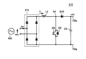
- FIG. 2 is a circuit diagram showing a preferred configuration example of the AC-DC converter 210.
- the AC-DC converter 210 is provided as a PFC circuit 210 for improving the power factor of the power supply voltage and power supply current from the external power supply 400.
- PFC circuit 210 includes a rectifier 212 configured by a diode bridge, an inductor L2, a switching element Q9 and an antiparallel diode D9, a diode D10, and a smoothing capacitor C2.
- the rectifier 212 rectifies and outputs the power supply voltage vac from the external power supply 400.
- Inductor L2 is connected between the positive output node of rectifier 212 and node N1.
- the negative output node of the rectifier 212 is connected to the ground wiring 152g.
- Switching element Q9 is electrically connected between node N1 and ground wiring 152g.
- An antiparallel diode D9 is provided for switching element Q9.
- the diode D10 is connected between the node N1 and the power supply wiring 152p with the direction from the node N1 toward the power supply wiring 152p as the forward direction.
- Smoothing capacitor C2 is connected between power supply line 152p and ground line 152g.
- power supply voltage vac from external power supply 400 is an AC voltage having a predetermined frequency (hereinafter referred to as “power supply frequency”).
- power supply frequency a predetermined frequency
- the current iL of the inductor L2 increases during the ON period of the switching element Q9, but decreases during the OFF period of the switching element Q9. Therefore, the current iL of the inductor L2 can be matched with the target current iL * by the on / off control of the switching element Q9 based on the output of a current sensor (not shown) for detecting the current iL.
- the current iL can be controlled so that the power supply current iac and the power supply voltage vac are in phase.
- the instantaneous power VA indicated by the product of the power supply current iac and the power supply voltage vac is always a positive value, so that the effective power that is the average value of the instantaneous power VA increases. That is, the power factor of the power supplied from the external power source 400 can be brought close to 1.
- the smoothing capacitor C2 is charged by a current supplied via the diode D10. Further, the current discharged from the smoothing capacitor C ⁇ b> 2 is supplied to the inverter 250 and used for charging the main battery 10. By these charging / discharging, the voltage of the smoothing capacitor C2, that is, the DC voltage vdc, fluctuates at a frequency twice the power supply frequency.
- the DC voltage vdc of the power supply wiring 152p can be controlled according to the magnitude (amplitude) iLA of the target current iL *. it can. That is, the PFC circuit 210 can control the DC voltage vdc according to the voltage command value vdc * along with the control of the current iL by turning on and off the switching element Q9. Specifically, when the DC voltage vdc is higher than the voltage command value vdc *, the power supply is reduced while the target current iL * (amplitude iLA) is increased when the DC voltage vdc is lower than the voltage command value vdc *. It is preferable to set it higher than the peak value of the voltage vac (for example, about 300 to 400 V).
- electric vehicle 5 turns on system main relays SMR1 and SMR2 and turns off charging relays CHR1 and CHR2 when the vehicle is traveling. Therefore, each device of the traveling system including the electric load 15 can be operated using the electric power of the main battery 10. On the other hand, when the vehicle travels, the charging system including charger 200 can be completely disconnected from main battery 10 and the traveling system by turning off charging relays CHR1 and CHR2.
- condition for starting the vehicle traveling includes that the charging cable 410 is not connected to the charging connector 105, so that the charging cable 410 is not connected to the charging connector 105 during vehicle traveling. Guaranteed to be.
- the main battery 10 can be charged with the electric power from the charger 200 by turning on the charging relays CHR1 and CHR2.
- charging relays CHR1 and CHR2 are turned off except during external charging.
- System main relays SMR1 and SMR2 are turned on or off according to the vehicle state, specifically, depending on the state of power consumption in the traveling system in response to a user operation.
- Control device 100 turns on system main relays SMR1 and SMR2 in accordance with a user operation or an operating state (or power consumption) of auxiliary devices 80 and 90 even during external charging.
- the system main relays SMR1 and SMR2 are turned on when the operation of the high-voltage auxiliary machine 90 such as an air conditioner is required or when the power consumption of the low-voltage auxiliary machine 80 increases.
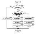
- FIG. 4 is a flowchart for explaining control of the charger in electric vehicle 5 according to the first embodiment of the present invention.
- the flowchart shown in FIG. 4 is executed at a predetermined cycle when the electric vehicle 5 is not running.
- control device 100 confirms whether or not external charging is being performed in step S100.
- Step S100 is determined as YES when the charging cable 410 is normally connected to the charging connector 105 and charging of the main battery 10 is not completed. On the other hand, when the charging cable 410 is not connected, or when external charging is not performed according to a user instruction or depending on the charging state of the main battery 10 even when the charging cable 410 is connected, the step is performed. S100 is NO.
- Control device 100 turns off charging relays CHR1 and CHR2 and turns off relays RL1 to RL3 of charger 200 in step S150 when external charging is not performed (NO in S100). As a result, the path through which the electric power from the external power source 400 is transmitted to the main battery 10 is cut off, so that the main battery 10 is not charged.
- Control device 100 turns on charging relays CHR1 and CHR2 during external charging (when YES is determined in S100), and advances the process to step S110.
- Control device 100 selects a charging mode of external charging in step S110. Specifically, it is determined whether or not the vehicle state requires insulation charging. Typically, the determination in step S110 is executed in response to on / off of system main relays SMR1 and SMR2 during external charging. As described above, whether or not the system main relays SMR1 and SMR2 need to be turned on is determined based on, for example, a user operation instruction to the auxiliary machines 80 and 90 or power consumption of the auxiliary machines 80 and 90. Can be determined.
- control device 100 selects YES in step S110 and selects the insulated charging mode (step S120).
- control device 100 determines NO in step S110 and selects the non-insulated charging mode (step S130).
- control device 100 When the isolated charging mode is selected, the control device 100 turns off the relays RL1 and RL2 in step S122, while turning on the relay RL3 in step S124. On the other hand, when the non-insulated charging mode is selected, control device 100 turns on relays RL1 and RL2 in step S132, and turns off relay RL3 in step S134.
- the inverter 250 converts the DC voltage vdc from the AC-DC converter (PFC circuit) 210 into an AC voltage by the on / off control of the switching elements Q1 to Q4, and supplies the AC voltage to the primary side of the insulating transformer 260. Output between connected wires 154 and 155. Since relays RL1 and RL2 are turned off, inverter 250 and converter 270 are electrically disconnected. On the other hand, since relay RL3 is turned on, the AC voltage output from inverter 250 to the primary side of isolation transformer 260 is transmitted between wirings 156 and 157 connected to the secondary side of isolation transformer 260.
- Converter 270 converts the AC voltage output to the secondary side (wirings 156 and 157) of insulating transformer 260 into a DC voltage and outputs it to power supply wiring 153p by on / off control of switching elements Q5 to Q8. Switching elements Q5 to Q8 are turned on / off so that the DC current or DC voltage input to main battery 10 via smoothing inductor L1 follows the control command value.
- the charger 200 charges the power from the external power source 400 to the main battery 10 through the power conversion path via the insulating transformer that ensures electrical insulation and transmits electrical energy. Convert to electricity.
- the external power source 400 since external charging can be performed in a state where the external power source 400 is electrically insulated from the main battery 10, even if the system main relays SMR1 and SMR2 are turned on, the external power source 400 is reliably connected between the electrical load 15 and the external power source 400. Insulation can be secured.
- inverter 250 bypasses switching elements Q5 to Q8 of converter 270 and is electrically connected to power supply wiring 153p and ground wiring 153g. Converter 270 is then stopped. That is, switching elements Q5 to Q8 are fixed off.
- relay RL3 since relay RL3 is turned off, the energization path on the primary side of isolation transformer 260 is interrupted. Therefore, transmission of electric energy by the isolation transformer 260 is not executed.
- a switching element (Q3 and Q4 in FIG. 1) connected to the smoothing inductor L1 by the relay RL1 and the smoothing inductor L1 form a non-insulated chopper circuit.
- the charger 200 operates. That is, of the switching elements Q1 to Q4, the switching elements (Q1 and Q2 in FIG. 1) that are not connected to the smoothing inductor L1 are fixed off.
- the charger 200 charges the main battery 10 with the DC voltage vdc from the AC-DC converter (PFC circuit) 210 by a non-insulated chopper circuit having the switching element Q3 as an upper arm and the switching element Q4 as a lower arm. Convert to voltage (Vb level).
- the switching elements Q3 and Q4 are complementarily turned on and off according to a predetermined switching cycle, and the on / off ratio (duty ratio) is controlled to thereby convert the voltage conversion ratio between the DC voltage vdc and the charging voltage of the main battery 10. Can be controlled.
- the charger 200 bypasses the insulating transformer 260 and is connected from the external power source 400 by the power conversion path in which the external power source 400 and the main battery 10 are electrically connected. Electric power is converted into charging power for the main battery 10.
- external charging can be performed with higher efficiency than in the insulating charging mode without causing loss in the insulating transformer 260.
- the electric load 15 and the external power source 400 are applied by applying the non-insulated charging mode. It is possible to increase the efficiency of external charging while ensuring insulation between the two.
- DC voltage vdc is set higher than the voltage of main battery 10, and charger 200 operates as a step-down chopper.
- the external charging (insulating charging mode) that secures the insulating performance by the power conversion path via the insulating transformer 260 (insulating mechanism) and the insulating transformer 260 (insulating mechanism) are provided.
- External charging non-insulated charging mode giving priority to high efficiency by the bypassed power conversion path can be selectively applied.
- in-vehicle electric equipment by switching between the insulated charging mode and the non-insulated charging mode in conjunction with the on / off of the system main relays SMR1, SMR2 for controlling the electrical connection between the main battery 10 and the electrical load 15 ( Highly efficient external charging can be performed while ensuring insulation between the electrical load 15) and the external power source 400.
- the relay RL1 can be modified so as to be connected between the power supply wiring 153p and the wiring 155.
- the smoothing inductor L1 and the switching elements Q3 and Q4 can constitute a non-insulated chopper circuit in the non-insulated charging mode.
- FIG. 6 is a block diagram showing an electric system configuration of the electric vehicle according to the modification of the first embodiment of the present invention.
- the arrangement of the relay RL2 in the charger 200 is different from the configuration of the first embodiment (first embodiment).
- the relay RL1 is connected between one wiring (wiring 154 in FIG. 6) on the primary side of the insulating transformer 260 and the power supply wiring 153p, similarly to the configuration of FIG.
- relay RL2 is connected between the other wiring (wiring 155 in FIG. 6) on the primary side of insulating transformer 260 and ground wiring 153g.
- the relay RL3 is inserted and connected to the primary energization path of the insulating transformer 260, similarly to the configuration of FIG. Since the configuration of other parts in FIG. 6 is the same as that of the first embodiment (FIG. 1), detailed description will not be repeated.
- the relays RL1 and RL2 are turned off and the relay RL3 is turned on, so that a power conversion path similar to that in the insulated charging mode in FIG. 1 is formed.
- the main battery 10 is charged using the power of the external power source 400.
- the relay RL3 is turned off while the relays RL1 and RL2 are turned on. Further, in inverter 250, the switching element (Q2 in the example of FIG. 6) connected between ground wirings 152g and 153g is fixed on via relay RL2.
- the non-insulated chopper circuit configured by the smoothing inductor L1 and the upper and lower arm switching elements (Q3 and Q4 in the example of FIG. 6) is included in FIG.
- a power conversion path similar to that in the non-insulated charging mode is formed. That is, the main battery 10 is charged using the power of the external power supply 400 through a power conversion path that electrically connects the external power supply 400 and the main battery 10, bypassing the isolation transformer 260.
- the electric vehicle 5 according to the modification of the first embodiment (FIG. 6) can also enjoy the same effects as the electric vehicle according to the first embodiment.
- the conversion function is ensured by a non-insulated chopper circuit. Therefore, when the voltage peak value from the external power supply 400 is guaranteed to be higher than the charging voltage of the main battery 10, the control of the output voltage (DC voltage vdc) of the AC-DC converter 210 is not necessarily performed. Not necessary. In other words, even if the AC-DC converter 210 is configured to simply execute AC-DC conversion by diode rectification or the like, external charging in the non-insulated charging mode can be realized.
- FIG. 7 is a block diagram showing an electric system configuration of the electric vehicle according to the second embodiment of the present invention.
- FIG. 7 is compared with FIG. 1, and the electric vehicle 5 according to the second embodiment is different from the electric vehicle according to the first embodiment shown in FIG. 1 in the arrangement of relays in the charger 200. Specifically, the arrangement of relay RL3 is omitted in electrically powered vehicle 5 according to the second embodiment. Further, relay RL1 is connected between power supply wiring 152p and power supply wiring 153p, while relay RL2 is connected between ground wiring 152g and ground wiring 153g. Since the configuration of other parts in FIG. 7 is the same as that of the first embodiment (FIG. 1), detailed description will not be repeated.
- selection of the insulated charging mode and the non-insulated charging mode is performed in the same manner as steps S110 to S130 in FIG.
- FIG. 8 shows the operation of charger 200 in the electrically powered vehicle according to Embodiment 2 during external charging (insulated charging mode / non-insulated charging mode).
- relays RL1 and RL2 are turned off in the insulated charging mode. That is, in the electric vehicle according to the second embodiment, when applying the charger control shown in FIG. 4, relays RL1 and RL2 are turned off in steps S122 and S124.
- the main battery 10 is charged using the power of the external power source 400 by forming a power conversion path similar to that in the isolated charging mode in FIG. That is, AC-DC converter (PFC circuit) 210, inverter 250, and converter 270 operate in the same manner as in the isolated charging mode in the first embodiment.
- AC-DC converter (PFC circuit) 210, inverter 250, and converter 270 operate in the same manner as in the isolated charging mode in the first embodiment.
- relays RL1 and RL2 are turned on. That is, in the electric vehicle according to the second embodiment, when applying the charger control shown in FIG. 4, relays RL1 and RL2 are turned on in steps S132 and S134.
- the operations of the inverter 250 and the converter 270 are stopped. That is, switching elements Q1-Q8 are all fixed off. For this reason, the voltage conversion function from the output voltage (DC voltage vdc) of the AC-DC converter (PFC circuit) 210 to the charging voltage of the main battery 10 is not ensured. That is, the output from the AC-DC converter (PFC circuit) 210 is directly used as the charging voltage and charging current of the main battery 10 via the relays RL1 and RL2.
- the output voltage vdc of the AC-DC converter 210 needs to be controlled to a voltage level corresponding to the charging voltage of the main battery 10. That is, the voltage command value vdc * is set to be equal to the charging voltage (Vb).
- the output current of the AC-DC converter 210 can also be realized by controlling the current iL in the PFC circuit 210 described with reference to FIGS.
- the electric vehicle 5 according to the second embodiment is not provided with a voltage conversion function for the output voltage vdc of the AC-DC converter 210 as compared with the electric vehicle according to the first embodiment.
- External switching in the non-insulated charging mode can be performed without switching all the switching elements Q1 to Q8 of 270. As a result, it is expected that the efficiency of external charging in the non-insulated charging mode is higher than that in the first embodiment.
- the relay RL1 is the same as in the first embodiment. , RL2 is turned off and the insulation charging mode is selected, so that insulation between the external power source 400 and the electric load 15 can be ensured.
- AC-DC converter 210 needs to have an output voltage (or output current) control function. As described in 1 above, it cannot be constituted by a simple diode rectifier.
- the insulating transformer 260 is exemplified as the insulating mechanism of the charger 200.
- the third embodiment a configuration example of an insulation mechanism other than an insulation transformer will be described.
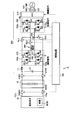
- FIG. 9 is a block diagram showing an electric system configuration of the electric vehicle according to the third embodiment of the present invention.
- electrically powered vehicle 5 according to the third embodiment includes charger 200 # in place of charger 200 as compared with electrically powered vehicle according to the first embodiment shown in FIG. 1. It is different. Since the configuration other than charger 200 # is similar to that of the first embodiment, detailed description thereof will not be repeated.
- charger 200 # includes an AC-DC converter 210, a charge pump circuit 260 #, and relays RL1 and RL2.
- relays RL1 and RL2 constitute a “first switch”.
- the AC-DC converter (PFC circuit) 210 converts AC power from the external power supply 400 transmitted to the charging connector 105 into DC power (DC voltage vdc) and outputs it to the power supply wiring 152p and the ground wiring 152g.
- the primary side of charge pump circuit 260 # is connected to power supply line 152p and ground line 152g.
- the secondary side of charge pump circuit 260 # is connected to power supply line 153p and ground line 153g.
- the power supply wiring 153p and the ground wiring 153g are electrically connected to the positive terminal and the negative terminal of the main battery 10 via the charging relays CHR1 and CHR2, respectively.
- Charge pump circuit 260 # includes a capacitor Cp, relays CR1a and CR1b provided on the primary side, and relays CR2a and CR2b provided on the secondary side.
- relay CR1a is connected between the positive terminal of capacitor Cp and power supply line 152p, and relay CR1b is connected between the negative terminal of capacitor Cp and ground line 152g. That is, the relays CR1a and CR1b correspond to a “third switch”.
- relay CR2a is connected between the positive terminal of capacitor Cp and power supply line 153p
- relay CR2b is connected between the negative terminal of capacitor Cp and ground line 153g. Is done. That is, the relays CR2a and CR2b correspond to a “fourth switch”.
- the relay RL1 is connected between the power supply wires 152p and 153p so as to form an energization path that bypasses the relays CR1a and CR2a.
- relay RL2 is connected to form an energization path that bypasses relays CR1b and CR2b between ground wirings 152g and 153g.
- relays CR1a, CR1b, CR2a, CR2b, relays R1, RL2, system main relays SMR1, SMR2, and charging relays CHR1, CHR2 are turned on (closed).
- the off state (opening) is controlled by the control device 100 (FIG. 1).
- FIG. 10 is a waveform diagram for explaining the operation at the time of external charging of the charger in the electric vehicle according to the third embodiment, specifically, the on / off operation of the plurality of relays shown in FIG.
- the insulated charging mode is selected between time t0 and t1, and the non-insulated charging mode is selected after time t2.
- the relays CR1a and CR1b and the relays CR2a and CR2b are turned on and off alternately and complementarily. As a result, the ON periods of the relays CR1a and CR1b and the ON periods of the relays CR2a and CR2b are alternately provided. On the other hand, relays RL1 and RL2 are fixed off.
- capacitor Cp is charged by the output voltage vdc of the AC-DC converter 210. At this time, capacitor Cp is electrically disconnected from power supply line 153p and ground line 153g (secondary side of charge pump circuit 260 #).
- charge pump circuit 260 # electrically insulates the primary side (power supply wiring 152p and ground wiring 152g) and secondary side (power supply wiring 153p and ground wiring 153g) of charge pump circuit 260 #, Electrical energy can be transmitted from the primary side to the secondary side. That is, charge pump circuit 260 # constitutes an “insulation mechanism”.
- charger 200 # can form a power conversion path that electrically isolates external power supply 400 and main battery 10 through charge pump circuit 260 # in the isolated charging mode. As a result. External charging of the main battery 10 can be performed in a state where the external power source 400 is electrically insulated from the main battery 10. Therefore, even if system main relays SMR1 and SMR2 are turned on, insulation can be reliably ensured between electric load 15 and external power supply 400.
- relays CR1a and CR2a and the relays CR1b and CR2b are fixed off.
- relays RL1 and RL2 are fixed on.
- charger 200 # bypasses charge pump circuit 260 # and is connected from external power supply 400 by a power conversion path in which external power supply 400 and main battery 10 are electrically connected. Is converted into the charging power of the main battery 10.
- charge pump circuit 260 # in the isolated charging mode, a switching loss occurs as each relay CR1a, CR2a, CR1b, CR2b is turned on / off. However, since the charge pump circuit 260 # is bypassed in the non-insulated charging mode, such a switching loss does not occur when the relays CR1a, CR2a, CR1b, CR2b are fixed off. That is, in the non-insulated charging mode, external charging can be executed with higher efficiency than in the insulating charging mode without causing loss in the charge pump circuit 260 # (insulating mechanism).
- the electric load 15 and the external power source 400 are applied by applying the non-insulated charging mode. It is possible to increase the efficiency of external charging while ensuring insulation between the two.
- charger 200 # according to Embodiment 3 is configured to have a voltage conversion function from the output voltage (DC voltage vdc) of AC-DC converter (PFC circuit) 210 to the charging voltage of main battery 10. Absent. Therefore, in each of the isolated charging mode and the non-insulated charging mode, output voltage vdc of AC-DC conversion circuit (PFC circuit) 210 needs to be controlled to a voltage level corresponding to the charging voltage of main battery 10. . That is, the voltage command value vdc * is set to be equal to the charging voltage (Vb).
- the output from the AC-DC converter (PFC circuit) 210 is directly used as the charging voltage and charging current of the main battery 10 via the relays RL1 and RL2.
- the converter 210 needs to be controlled as in the second embodiment.
- the isolated charging mode and the non-insulated charging mode can be changed to the first embodiment and its modifications. Similar to the example and the second embodiment, it can be used properly.
- external charging insulating charging mode
- charge pump circuit 260 # insulating mechanism
- insulating transformer 260 insulating mechanism
- steps S110 to S130 for selecting the insulating charging mode and the non-insulating charging mode are the same as those in FIG.
- steps S122 and S124 the relays RL1 and RL2 are turned off, and in steps S132 and S134, the process may be changed so that the relays RL1 and RL2 are turned on.
- the configuration of the charger 200 particularly the configurations of the AC-DC converter 210, the inverter 250, and the converter 270 are the same as those shown in FIGS.
- the point which is not limited to the illustration in is described definitely.
- the AC-DC converter 210 is a power converter that can convert the power supply voltage vac from the external power supply 400 into a DC voltage
- a circuit configuration different from that illustrated in FIG. 2 can be applied.
- the inverter 250 and the converter 270 can perform equivalent DC-AC conversion and AC-DC conversion when the power conversion path via the isolation transformer 260 is formed (insulated charging mode) and is insulated.
- a non-insulated DC voltage converter can be configured using the smoothing inductor L1 when the power conversion path bypassing the transformer 260 is formed, a circuit configuration different from the example in FIG. Can do.
- the present invention can be applied to an electric vehicle such as a hybrid vehicle, an electric vehicle not equipped with an engine, or a fuel cell vehicle equipped with an in-vehicle power storage device that can be charged by a power source external to the vehicle.
- an electric vehicle such as a hybrid vehicle, an electric vehicle not equipped with an engine, or a fuel cell vehicle equipped with an in-vehicle power storage device that can be charged by a power source external to the vehicle.
Landscapes
- Engineering & Computer Science (AREA)
- Power Engineering (AREA)
- Transportation (AREA)
- Mechanical Engineering (AREA)
- Life Sciences & Earth Sciences (AREA)
- Sustainable Development (AREA)
- Sustainable Energy (AREA)
- Electric Propulsion And Braking For Vehicles (AREA)
- Charge And Discharge Circuits For Batteries Or The Like (AREA)
- Secondary Cells (AREA)
- Dc-Dc Converters (AREA)
Abstract
Priority Applications (5)
| Application Number | Priority Date | Filing Date | Title |
|---|---|---|---|
| JP2012525275A JP5348326B2 (ja) | 2010-07-22 | 2010-07-22 | 電動車両およびその充電制御方法 |
| CN201080066720.8A CN102892615B (zh) | 2010-07-22 | 2010-07-22 | 电动车辆及其充电控制方法 |
| EP10855013.8A EP2596979A4 (fr) | 2010-07-22 | 2010-07-22 | Véhicule entraîné électriquement et son procédé de commande de chargement |
| PCT/JP2010/062322 WO2012011176A1 (fr) | 2010-07-22 | 2010-07-22 | Véhicule entraîné électriquement et son procédé de commande de chargement |
| US13/497,163 US8810206B2 (en) | 2010-07-22 | 2010-07-22 | Electric motored vehicle and method for controlling electrically charging the same |
Applications Claiming Priority (1)
| Application Number | Priority Date | Filing Date | Title |
|---|---|---|---|
| PCT/JP2010/062322 WO2012011176A1 (fr) | 2010-07-22 | 2010-07-22 | Véhicule entraîné électriquement et son procédé de commande de chargement |
Publications (1)
| Publication Number | Publication Date |
|---|---|
| WO2012011176A1 true WO2012011176A1 (fr) | 2012-01-26 |
Family
ID=45496616
Family Applications (1)
| Application Number | Title | Priority Date | Filing Date |
|---|---|---|---|
| PCT/JP2010/062322 WO2012011176A1 (fr) | 2010-07-22 | 2010-07-22 | Véhicule entraîné électriquement et son procédé de commande de chargement |
Country Status (5)
| Country | Link |
|---|---|
| US (1) | US8810206B2 (fr) |
| EP (1) | EP2596979A4 (fr) |
| JP (1) | JP5348326B2 (fr) |
| CN (1) | CN102892615B (fr) |
| WO (1) | WO2012011176A1 (fr) |
Cited By (10)
| Publication number | Priority date | Publication date | Assignee | Title |
|---|---|---|---|---|
| JP2013143788A (ja) * | 2012-01-06 | 2013-07-22 | Nippon Soken Inc | 車両 |
| JP2013162649A (ja) * | 2012-02-06 | 2013-08-19 | Daihen Corp | 電力変換装置 |
| WO2016050392A1 (fr) * | 2014-10-01 | 2016-04-07 | Robert Bosch Gmbh | Circuit de charge pour un accumulateur d'énergie électrique, système d'entraînement électrique et procédé pour faire fonctionner un circuit de charge |
| JP2018082616A (ja) * | 2016-11-16 | 2018-05-24 | ドクター エンジニール ハー ツェー エフ ポルシェ アクチエンゲゼルシャフトDr. Ing. h.c. F. Porsche Aktiengesellschaft | 車両、特に電気自動車またはハイブリッド車両、および車両のエネルギー貯蔵セルを充電する方法 |
| WO2018159022A1 (fr) * | 2017-03-02 | 2018-09-07 | パナソニックIpマネジメント株式会社 | Dispositif de charge et dispositif d'alimentation électrique embarqué |
| JP2019531043A (ja) * | 2016-09-22 | 2019-10-24 | イエフペ・エネルジェ・ヌーヴェル | 変換デバイス、関連する制御方法および関連する車両 |
| JP2019531689A (ja) * | 2016-11-08 | 2019-10-31 | 日産自動車株式会社 | 電気またはハイブリッド車両の車載充電装置用の三相整流器を制御する方法 |
| JP2019531688A (ja) * | 2016-11-10 | 2019-10-31 | 日産自動車株式会社 | 電気またはハイブリッド車両の車載充電装置用の三相整流器を制御する方法 |
| CN110474410A (zh) * | 2019-08-15 | 2019-11-19 | 深圳威迈斯新能源股份有限公司 | 车载集成充电装置及其电流分配计算方法 |
| US11355947B2 (en) * | 2018-12-18 | 2022-06-07 | Hyundai Motor Company | Apparatus incorporating non-isolated charger and DC converter |
Families Citing this family (34)
| Publication number | Priority date | Publication date | Assignee | Title |
|---|---|---|---|---|
| EP2722961A4 (fr) * | 2011-06-17 | 2016-02-10 | Toyota Motor Co Ltd | Système d'alimentation électrique, véhicule doté de celui-ci et procédé de commande de système d'alimentation électrique |
| US10122293B2 (en) * | 2012-01-17 | 2018-11-06 | Infineon Technologies Americas Corp. | Power module package having a multi-phase inverter and power factor correction |
| KR102040632B1 (ko) * | 2012-05-11 | 2019-11-05 | 후지 덴키 가부시키가이샤 | 모터 구동 장치 |
| DE102012111968B4 (de) * | 2012-12-07 | 2022-12-15 | Sick Ag | Sensor und ein Verfahren zur Herstellung des Sensors |
| JP6193681B2 (ja) * | 2013-08-30 | 2017-09-06 | ヤンマー株式会社 | エンジン発電機 |
| KR101567648B1 (ko) * | 2013-12-18 | 2015-11-10 | 현대자동차주식회사 | 배터리 충전 시스템 및 장치 |
| KR101516899B1 (ko) * | 2013-12-31 | 2015-05-04 | 현대모비스 주식회사 | 차량용 전력 변환 장치 및 이의 제어 방법 |
| TWI559648B (zh) * | 2014-01-21 | 2016-11-21 | 台達電子工業股份有限公司 | 動態充電之充電裝置及其操作方法 |
| US20160190954A1 (en) * | 2014-12-31 | 2016-06-30 | Avogy, Inc. | Method and system for bridgeless ac-dc converter |
| DE102015101094A1 (de) * | 2015-01-27 | 2016-07-28 | Dr. Ing. H.C. F. Porsche Aktiengesellschaft | Ladesteuerung für eine Batterie in einem Fahrzeug |
| FR3035282B1 (fr) * | 2015-04-15 | 2018-05-11 | Valeo Siemens Eautomotive France Sas | Chargeur de batterie, installation electrique et vehicule automobile |
| JP6288134B2 (ja) * | 2016-03-22 | 2018-03-07 | トヨタ自動車株式会社 | 自動車 |
| DE102016105542A1 (de) | 2016-03-24 | 2017-09-28 | Dr. Ing. H.C. F. Porsche Aktiengesellschaft | Verfahren zum Betreiben eines elektrischen Netzes |
| US10511223B2 (en) | 2016-12-09 | 2019-12-17 | Allegro Microsystems, Llc | Voltage regulator having boost and charge pump functionality |
| CN106936325A (zh) * | 2016-12-21 | 2017-07-07 | 蔚来汽车有限公司 | 多功能车载功率变换器和包含其的电动汽车 |
| DE102017110708A1 (de) | 2017-05-17 | 2018-11-22 | Dr. Ing. H.C. F. Porsche Aktiengesellschaft | Verfahren zum Betreiben eines elektrischen Netzes |
| DE102017110709A1 (de) | 2017-05-17 | 2018-11-22 | Dr. Ing. H.C. F. Porsche Aktiengesellschaft | Verfahren zum Betreiben eines elektrischen Netzes |
| KR102454222B1 (ko) * | 2017-07-21 | 2022-10-17 | 현대자동차주식회사 | 전기 자동차 |
| CN107585032A (zh) * | 2017-08-10 | 2018-01-16 | 清华大学 | 电动汽车的电子电气系统 |
| JP6554151B2 (ja) * | 2017-08-31 | 2019-07-31 | 本田技研工業株式会社 | 車両の電源システム |
| JP6545230B2 (ja) * | 2017-08-31 | 2019-07-17 | 本田技研工業株式会社 | 車両の電源システム |
| KR102008753B1 (ko) * | 2017-09-12 | 2019-08-09 | 현대오트론 주식회사 | 차량용 전력 제어 장치 |
| KR102008752B1 (ko) * | 2017-09-12 | 2019-08-12 | 현대오트론 주식회사 | 차량용 전력 제어 장치 |
| KR102008751B1 (ko) * | 2017-09-12 | 2019-08-12 | 현대오트론 주식회사 | 차량용 전력 제어 장치 |
| JP6885302B2 (ja) * | 2017-11-08 | 2021-06-09 | トヨタ自動車株式会社 | 車両用電源システム |
| JP7010035B2 (ja) | 2018-02-06 | 2022-01-26 | トヨタ自動車株式会社 | 電動車両 |
| US11351885B2 (en) * | 2018-04-20 | 2022-06-07 | Siemens Aktiengesellschaft | Charging infrastructure unit, and charging infrastructure having a charging power option |
| JP7067434B2 (ja) * | 2018-11-15 | 2022-05-16 | トヨタ自動車株式会社 | 充電装置 |
| JP2020108265A (ja) * | 2018-12-27 | 2020-07-09 | トヨタ自動車株式会社 | 車両用電源システム |
| JP2020145850A (ja) * | 2019-03-06 | 2020-09-10 | トヨタ自動車株式会社 | 車両用電源システム |
| CN112776624A (zh) * | 2021-02-03 | 2021-05-11 | 爱驰汽车有限公司 | 车对车充电系统、方法及电动汽车 |
| CN113484629B (zh) * | 2021-05-31 | 2024-05-03 | 北京航天光华电子技术有限公司 | 一种电子电气设备通用测试系统 |
| US11613184B1 (en) * | 2021-10-31 | 2023-03-28 | Beta Air, Llc | Systems and methods for disabling an electric vehicle during charging |
| KR102389150B1 (ko) * | 2022-01-20 | 2022-04-21 | 김부광 | 엘리베이터의 비상구출장치 |
Citations (6)
| Publication number | Priority date | Publication date | Assignee | Title |
|---|---|---|---|---|
| WO2009028520A1 (fr) * | 2007-08-24 | 2009-03-05 | Toyota Jidosha Kabushiki Kaisha | Véhicule |
| JP2009225568A (ja) * | 2008-03-17 | 2009-10-01 | Toyota Motor Corp | 燃料電池車両システム |
| JP2010081734A (ja) * | 2008-09-26 | 2010-04-08 | Toyota Motor Corp | 電動車両及び電動車両の充電制御方法 |
| WO2010061465A1 (fr) * | 2008-11-28 | 2010-06-03 | トヨタ自動車株式会社 | Système de charge de véhicule |
| WO2010067417A1 (fr) * | 2008-12-09 | 2010-06-17 | トヨタ自動車株式会社 | Système d'alimentation électrique de véhicule |
| WO2010070761A1 (fr) * | 2008-12-19 | 2010-06-24 | トヨタ自動車株式会社 | Véhicule hybride |
Family Cites Families (17)
| Publication number | Priority date | Publication date | Assignee | Title |
|---|---|---|---|---|
| US4296296A (en) * | 1979-08-13 | 1981-10-20 | General Electric Company | Controllable-duty-cycle power supply for microwave oven magnetron and the like |
| FR2695266B1 (fr) * | 1992-09-02 | 1994-09-30 | Cableco Sa | Ensemble pour recharger les batteries d'accumulateurs d'un véhicule automobile électrique. |
| JPH0888908A (ja) | 1994-09-14 | 1996-04-02 | Hitachi Ltd | 電気車用充電装置 |
| JP3228097B2 (ja) * | 1995-10-19 | 2001-11-12 | 株式会社日立製作所 | 充電システム及び電気自動車 |
| DE60220560T2 (de) * | 2001-01-27 | 2007-10-18 | Sma Technologie Ag | Mittelfrequenz-Energieversorgung für ein Schienenfahrzeug |
| US7178513B2 (en) * | 2002-04-19 | 2007-02-20 | Ward Michael A V | MCU based high energy ignition |
| US7274112B2 (en) * | 2004-08-31 | 2007-09-25 | American Power Conversion Corporation | Method and apparatus for providing uninterruptible power |
| JP4144646B1 (ja) * | 2007-02-20 | 2008-09-03 | トヨタ自動車株式会社 | 電動車両、車両充電装置および車両充電システム |
| JP4770798B2 (ja) * | 2007-06-15 | 2011-09-14 | 株式会社豊田自動織機 | 電源装置 |
| JP4315232B1 (ja) | 2008-03-17 | 2009-08-19 | トヨタ自動車株式会社 | 電動車両 |
| JP2009274479A (ja) | 2008-05-12 | 2009-11-26 | Toyota Motor Corp | ハイブリッド車両 |
| JP5285418B2 (ja) * | 2008-12-24 | 2013-09-11 | 株式会社豊田自動織機 | 共鳴型非接触電力供給装置 |
| JP5510032B2 (ja) * | 2009-05-14 | 2014-06-04 | 日産自動車株式会社 | 非接触給電装置 |
| US8350523B2 (en) * | 2009-08-05 | 2013-01-08 | GM Global Technology Operations LLC | Charging system with galvanic isolation and multiple operating modes |
| WO2011016328A1 (fr) * | 2009-08-06 | 2011-02-10 | ヤンマー株式会社 | Circuit de convertisseur continu-continu |
| JP4905571B2 (ja) * | 2010-03-10 | 2012-03-28 | トヨタ自動車株式会社 | 車両の駐車支援装置およびそれを備える車両 |
| EP2388902B1 (fr) * | 2010-05-21 | 2013-08-14 | C.R.F. Società Consortile per Azioni | Système et procédé pour la commande numérique d'un dispositif de conversion de puissance CC/CC, en particulier pour des applications automobiles |
-
2010
- 2010-07-22 EP EP10855013.8A patent/EP2596979A4/fr not_active Withdrawn
- 2010-07-22 US US13/497,163 patent/US8810206B2/en not_active Expired - Fee Related
- 2010-07-22 JP JP2012525275A patent/JP5348326B2/ja not_active Expired - Fee Related
- 2010-07-22 CN CN201080066720.8A patent/CN102892615B/zh not_active Expired - Fee Related
- 2010-07-22 WO PCT/JP2010/062322 patent/WO2012011176A1/fr active Application Filing
Patent Citations (6)
| Publication number | Priority date | Publication date | Assignee | Title |
|---|---|---|---|---|
| WO2009028520A1 (fr) * | 2007-08-24 | 2009-03-05 | Toyota Jidosha Kabushiki Kaisha | Véhicule |
| JP2009225568A (ja) * | 2008-03-17 | 2009-10-01 | Toyota Motor Corp | 燃料電池車両システム |
| JP2010081734A (ja) * | 2008-09-26 | 2010-04-08 | Toyota Motor Corp | 電動車両及び電動車両の充電制御方法 |
| WO2010061465A1 (fr) * | 2008-11-28 | 2010-06-03 | トヨタ自動車株式会社 | Système de charge de véhicule |
| WO2010067417A1 (fr) * | 2008-12-09 | 2010-06-17 | トヨタ自動車株式会社 | Système d'alimentation électrique de véhicule |
| WO2010070761A1 (fr) * | 2008-12-19 | 2010-06-24 | トヨタ自動車株式会社 | Véhicule hybride |
Non-Patent Citations (1)
| Title |
|---|
| See also references of EP2596979A4 * |
Cited By (16)
| Publication number | Priority date | Publication date | Assignee | Title |
|---|---|---|---|---|
| JP2013143788A (ja) * | 2012-01-06 | 2013-07-22 | Nippon Soken Inc | 車両 |
| JP2013162649A (ja) * | 2012-02-06 | 2013-08-19 | Daihen Corp | 電力変換装置 |
| WO2016050392A1 (fr) * | 2014-10-01 | 2016-04-07 | Robert Bosch Gmbh | Circuit de charge pour un accumulateur d'énergie électrique, système d'entraînement électrique et procédé pour faire fonctionner un circuit de charge |
| JP2017536793A (ja) * | 2014-10-01 | 2017-12-07 | ロベルト・ボッシュ・ゲゼルシャフト・ミト・ベシュレンクテル・ハフツングRobert Bosch Gmbh | 電気エネルギー蓄積器のための充電回路、電気駆動システム、および充電回路を作動する方法 |
| US10286786B2 (en) | 2014-10-01 | 2019-05-14 | Robert Bosch Gmbh | Charging circuit for an electrical energy accumulator, electrical drive system and method for operating a charging circuit |
| JP2019531043A (ja) * | 2016-09-22 | 2019-10-24 | イエフペ・エネルジェ・ヌーヴェル | 変換デバイス、関連する制御方法および関連する車両 |
| JP2019531689A (ja) * | 2016-11-08 | 2019-10-31 | 日産自動車株式会社 | 電気またはハイブリッド車両の車載充電装置用の三相整流器を制御する方法 |
| JP2019531688A (ja) * | 2016-11-10 | 2019-10-31 | 日産自動車株式会社 | 電気またはハイブリッド車両の車載充電装置用の三相整流器を制御する方法 |
| US10421364B2 (en) | 2016-11-16 | 2019-09-24 | Dr. Ing. H.C. F. Porsche Aktiengesellschaft | Vehicle, in particular an electric vehicle or a hybrid vehicle, and method for charging an energy storage cell of a vehicle |
| JP2018082616A (ja) * | 2016-11-16 | 2018-05-24 | ドクター エンジニール ハー ツェー エフ ポルシェ アクチエンゲゼルシャフトDr. Ing. h.c. F. Porsche Aktiengesellschaft | 車両、特に電気自動車またはハイブリッド車両、および車両のエネルギー貯蔵セルを充電する方法 |
| JP2018148637A (ja) * | 2017-03-02 | 2018-09-20 | パナソニックIpマネジメント株式会社 | 充電装置、及び車載電源装置 |
| WO2018159022A1 (fr) * | 2017-03-02 | 2018-09-07 | パナソニックIpマネジメント株式会社 | Dispositif de charge et dispositif d'alimentation électrique embarqué |
| US11043831B2 (en) | 2017-03-02 | 2021-06-22 | Panasonic Intellectual Property Management Co., Ltd. | Charging device and on board power supply device |
| US11355947B2 (en) * | 2018-12-18 | 2022-06-07 | Hyundai Motor Company | Apparatus incorporating non-isolated charger and DC converter |
| CN110474410A (zh) * | 2019-08-15 | 2019-11-19 | 深圳威迈斯新能源股份有限公司 | 车载集成充电装置及其电流分配计算方法 |
| CN110474410B (zh) * | 2019-08-15 | 2023-08-29 | 深圳威迈斯新能源股份有限公司 | 车载集成充电装置及其电流分配计算方法 |
Also Published As
| Publication number | Publication date |
|---|---|
| CN102892615A (zh) | 2013-01-23 |
| JP5348326B2 (ja) | 2013-11-20 |
| US20130106365A1 (en) | 2013-05-02 |
| CN102892615B (zh) | 2014-12-10 |
| EP2596979A1 (fr) | 2013-05-29 |
| US8810206B2 (en) | 2014-08-19 |
| EP2596979A4 (fr) | 2017-03-29 |
| JPWO2012011176A1 (ja) | 2013-09-09 |
Similar Documents
| Publication | Publication Date | Title |
|---|---|---|
| JP5348326B2 (ja) | 電動車両およびその充電制御方法 | |
| US10994623B2 (en) | Apparatus for energy transfer using converter and method of manufacturing same | |
| JP5348334B2 (ja) | 電動車両の電源装置およびその制御方法 | |
| JP5267740B1 (ja) | 車両の電源システム | |
| US8963482B2 (en) | Power supply apparatus for electrically powered vehicle and method for controlling the same | |
| CN106026318B (zh) | 使用具有高频变压器隔离的车载功率电子设备转移能量的设备及其制造方法 | |
| WO2012144045A1 (fr) | Appareil d'alimentation en énergie pour véhicule à propulsion électrique et procédé de commande de celui-ci | |
| WO2007026942A1 (fr) | Module de regulation de charge et vehicule electrique | |
| WO2013132604A1 (fr) | Véhicule électrique et procédé de commande de celui-ci | |
| JP5767123B2 (ja) | 車両 | |
| KR102008751B1 (ko) | 차량용 전력 제어 장치 | |
| WO2013046315A1 (fr) | Système d'alimentation pour véhicule électrique | |
| KR102008753B1 (ko) | 차량용 전력 제어 장치 | |
| KR102063921B1 (ko) | 차량용 전력 제어 장치 | |
| KR102008750B1 (ko) | 차량용 전력 제어 장치 | |
| KR102008746B1 (ko) | 차량용 전력 제어 장치 | |
| KR102008752B1 (ko) | 차량용 전력 제어 장치 | |
| KR102008747B1 (ko) | 차량용 전력 제어 장치 | |
| KR102008748B1 (ko) | 차량용 전력 제어 장치 | |
| KR102008749B1 (ko) | 차량용 전력 제어 장치 | |
| JP2022107885A (ja) | 車両の電力システム |
Legal Events
| Date | Code | Title | Description |
|---|---|---|---|
| WWE | Wipo information: entry into national phase |
Ref document number: 201080066720.8 Country of ref document: CN |
|
| 121 | Ep: the epo has been informed by wipo that ep was designated in this application |
Ref document number: 10855013 Country of ref document: EP Kind code of ref document: A1 |
|
| WWE | Wipo information: entry into national phase |
Ref document number: 13497163 Country of ref document: US |
|
| REEP | Request for entry into the european phase |
Ref document number: 2010855013 Country of ref document: EP |
|
| WWE | Wipo information: entry into national phase |
Ref document number: 2010855013 Country of ref document: EP |
|
| WWE | Wipo information: entry into national phase |
Ref document number: 2012525275 Country of ref document: JP |
|
| NENP | Non-entry into the national phase |
Ref country code: DE |