以下、添付図面を参照して、本発明の実施形態を説明する。
Hereinafter, embodiments of the present invention will be described with reference to the accompanying drawings.
(第1の実施形態)
図1~54を参照して、本発明に係るX線断層像撮影装置としての歯科用X線口外撮影装置の第1の実施形態を説明する。
(First embodiment)
A first embodiment of a dental X-ray extraoral imaging apparatus as an X-ray tomographic imaging apparatus according to the present invention will be described with reference to FIGS.
このX線口外撮影装置は、被検体Pの顎部の撮像対象(歯列など)を顎部の外部からX線でスキャンし、このスキャンで収集したデータをトモシンセス法で処理し、その撮像対象の断層像を生成するモダリティである。このため、本実施形態に係るX線口外撮影装置は、既存の歯科治療で用いられているパノラマ撮像装置の機能は勿論のこと、従来のパノラマ撮像装置では得られなかった、小形・軽量化、高分解能な画像の提供、放射線管理区域として撮像室を設けなければならないという不便さに由来するワークフローの改善など、本発明の目的を達成し得る。
This X-ray extra-oral imaging apparatus scans an object to be imaged (such as a dentition) of the jaw of the subject P with an X-ray from the outside of the jaw, processes the data collected by this scan by the tomosynthesis method, This is a modality that generates a tomographic image. For this reason, the X-ray extraoral imaging apparatus according to the present embodiment is not only the function of the panoramic imaging apparatus used in the existing dental treatment, but also a small size and light weight that cannot be obtained by the conventional panoramic imaging apparatus. The object of the present invention can be achieved, such as providing a high-resolution image and improving a workflow derived from the inconvenience of having to provide an imaging room as a radiation control area.
<基本構成>
この実施形態では、最初に、本実施形態に係るX線口外撮影装置の基本構成を説明する。その後で、このX線口外撮影装置の設置の様々な具体例を変形例として説明する。
<Basic configuration>
In this embodiment, first, the basic configuration of the X-ray extraoral imaging apparatus according to this embodiment will be described. Thereafter, various specific examples of the installation of the X-ray extraoral imaging apparatus will be described as modified examples.
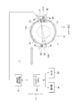
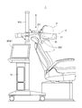
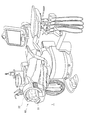
図1に、実施形態に係るX線口外撮影装置1の基本構成を示す。このX線口外撮影装置1は、被検体P(患者)の口外から、その被検体Pの歯列を含む顎部の内部構造を示すパノラマ画像、及び、このパノラマ画像を用いて3次元(3D)断層像を提供するモダリティである。
FIG. 1 shows a basic configuration of an X-ray extraoral imaging apparatus 1 according to the embodiment. The X-ray extra-oral imaging apparatus 1 uses a panoramic image showing the internal structure of the jaw including the dentition of the subject P from outside the subject P (patient), and three-dimensional (3D) using the panoramic image. ) Modality that provides a tomographic image.
このX線口外撮影装置1は、その基本要素として、顎部に対してX線によるスキャンを行ってX線透過データを収集するスキャン装置10と、このスキャン装置10のスキャン動作に関わる駆動を制御するとともに、スキャン装置10が収集したX線透過データを受けて画像を再構成するコンピュータ11と、スキャン装置10に高電圧を供給する高電圧発生装置12とを備える。なお、本実施形態で言うスキャンとは、被検体Pの撮像部位に対して予め定めた複数のパスのそれぞれに沿ってX線(X線ビームXB)を照射し、画像再構成に必要な分のX線透過データのセットを収集する一連の動作である。
The X-ray extraoral imaging apparatus 1 controls, as its basic elements, a scanning apparatus 10 that performs X-ray scanning on the jaw and collects X-ray transmission data, and driving related to the scanning operation of the scanning apparatus 10. In addition, a computer 11 that receives X-ray transmission data collected by the scanning device 10 and reconstructs an image, and a high voltage generator 12 that supplies a high voltage to the scanning device 10 are provided. The scan referred to in the present embodiment is an amount necessary for image reconstruction by irradiating an X-ray (X-ray beam XB) along each of a plurality of predetermined paths with respect to the imaging region of the subject P. Is a series of operations for collecting a set of X-ray transmission data.
スキャン装置10は、後述の変形例で説明するように様々な設置方法によって被検体Pの顎部(撮像部位)の周りに近接し、その顎部を囲うように配置される。具体的には、スキャン装置10は、図1及び図3から分かるように、円状の軌道OBを提供する円形のリング体21を有する。軌道OBは、リング体21の外側面を成す円周面に沿って仮想的に創生される円軌道である。
The scanning device 10 is arranged so as to be close to and surround the jaw (imaging site) of the subject P by various installation methods as will be described in the following modification. Specifically, as can be seen from FIGS. 1 and 3, the scanning apparatus 10 includes a circular ring body 21 that provides a circular orbit OB. The orbit OB is a circular orbit created virtually along the circumferential surface that forms the outer surface of the ring body 21.
スキャン時には、このリング体21が被検体Pの顎部の周りに配置される。この配置の仕方は様々である。例えば後述の変形例で説明するように、リング体21を歯科用の治療椅子のヘッドレストに固定的に又は着脱自在に設置してもよい。また、治療椅子とは別体のC形状のアームを用意し、このアームにリング体21を支持させてもよい。さらに、被検体Pの肩部及び/又は頭部に載せたホルダに、このリング体21を支持させるようにしてもよい。要するに、スキャン時にリング体21を被検体Pの顎部の周りに位置させることができ、且つ、スキャンに必要なX線の量を減らすために、リング体21の径を極力小さくして、小形化することが望ましい。
At the time of scanning, the ring body 21 is arranged around the jaw of the subject P. There are various ways of arrangement. For example, as will be described in a later-described modification, the ring body 21 may be fixedly or detachably installed on the headrest of a dental treatment chair. Further, a C-shaped arm separate from the treatment chair may be prepared, and the ring body 21 may be supported by this arm. Furthermore, the ring body 21 may be supported by a holder placed on the shoulder and / or head of the subject P. In short, the ring body 21 can be positioned around the jaw of the subject P at the time of scanning, and in order to reduce the amount of X-rays required for scanning, the ring body 21 is made as small as possible by reducing the diameter thereof. It is desirable to make it.
なお、図1に示す如く、リング体21に対して、このリング体21が提供する軌道OBに沿った2次元面をXY面とするX軸、Y軸、及びZ軸から成る直交座標を設定し、必要に応じて、これらの座標軸を用いて説明する。
In addition, as shown in FIG. 1, orthogonal coordinates composed of an X-axis, a Y-axis, and a Z-axis are set with respect to the ring body 21 with the two-dimensional surface along the trajectory OB provided by the ring body 21 as the XY plane. Then, description will be made using these coordinate axes as necessary.
このリング体21は、前述のように、この外周面に沿った仮想的な円形の軌道OBを提供する。同時に、このリング体21は、スキャンを実施するため、X線管31を備えるX線管ユニット31Uと検出器32を備える検出器ユニット32Uとをその軌道OBに沿って移動可能に支持している。リング体21の外周面には、その周方向に沿って、例えばベアリング(図示せず)が形成されている。
The ring body 21 provides a virtual circular orbit OB along the outer peripheral surface as described above. At the same time, the ring body 21 supports an X-ray tube unit 31U including the X-ray tube 31 and a detector unit 32U including the detector 32 so as to be movable along the orbit OB in order to perform scanning. . For example, a bearing (not shown) is formed on the outer circumferential surface of the ring body 21 along the circumferential direction.
X線管ユニット31Uは、X線管31のほかに、このユニット31Uを軌道OBに沿って移動させるウォームギヤなどの移動機構41と、この移動機構41を移動させる電動モータ42とを備える。さらに、本実施形態では、このX線管ユニット31Uに、コリメータ33と、このコリメータ33をX線管31に対して相対的に移動可能な超音波モータ、ねじ機構などの駆動部34とを備える。
In addition to the X-ray tube 31, the X-ray tube unit 31U includes a moving mechanism 41 such as a worm gear that moves the unit 31U along the track OB, and an electric motor 42 that moves the moving mechanism 41. Further, in the present embodiment, the X-ray tube unit 31U includes a collimator 33 and a drive unit 34 such as an ultrasonic motor or a screw mechanism that can move the collimator 33 relative to the X-ray tube 31. .
なお、X線管31及び検出器32が回転しながらX線によるスキャンが実行されるので、リング体21が供する円形軌道OBによって囲まれる内部の空間は撮像空間ISを形成している。
In addition, since the X-ray scan is executed while the X-ray tube 31 and the detector 32 are rotated, the internal space surrounded by the circular orbit OB provided by the ring body 21 forms an imaging space IS.
X線管31は、例えば回転陽極型の真空管型のX線管、又は、電界放射型カーボンナノチューブカソードを用いたパルス点灯型のX線管で構成されており、そのターゲット(陽極)からX線を検出器22向けて放射状に放射させる。このターゲットに衝突させる電子線の焦点(いわゆるX線管焦点)の径は0.25mm以下と小さく、したがって、このX線管21は点状のX線源として機能する。
The X-ray tube 31 is composed of, for example, a rotary anode type vacuum tube type X-ray tube or a pulse lighting type X-ray tube using a field emission type carbon nanotube cathode, and an X-ray from the target (anode). Are emitted radially toward the detector 22. The diameter of the focal point (so-called X-ray tube focal point) of the electron beam colliding with the target is as small as 0.25 mm or less, and therefore the X-ray tube 21 functions as a point-like X-ray source.
X線管21の前面側の所定位置には、スリット状の開口を有するコリメータ33が位置付けられている。X線管21から曝射されたX線は、このコリメータ33の開口を通過する。このため、検出器32に入射させるX線を、その検出面(すなわち実際の収集用の窓(例えば5.0mm幅の窓))に絞ることができる。コリメータ33は、移動機構34によってその位置及び姿勢、又は、位置のみが移動可能に形成されている。コリメータ33及び移動機構34は、X線管ユニット31Uの内部に設置されているため、X線管31と伴に移動する。
A collimator 33 having a slit-like opening is positioned at a predetermined position on the front side of the X-ray tube 21. X-rays exposed from the X-ray tube 21 pass through the opening of the collimator 33. For this reason, the X-rays incident on the detector 32 can be focused on the detection surface (that is, an actual collection window (for example, a window having a width of 5.0 mm)). The collimator 33 is formed so that the position and posture of the collimator 33 or only the position can be moved by the moving mechanism 34. Since the collimator 33 and the moving mechanism 34 are installed inside the X-ray tube unit 31U, they move together with the X-ray tube 31.
X線管ユニット31Uと同様に、検出器ユニット32Uは、X線を検出する検出器32のほかに、このユニット32Uを軌道OBに沿って移動させるウォームギヤなどの移動機構51と、この移動機構51を移動させる電動モータ52とを備える。
Similar to the X-ray tube unit 31U, the detector unit 32U includes a moving mechanism 51 such as a worm gear for moving the unit 32U along the track OB, in addition to the detector 32 for detecting X-rays, and the moving mechanism 51. And an electric motor 52 that moves the motor.
一方、検出器32は、放射線検出手段として機能するデバイスであり、X線検出素子を2次元状(例えば、64×1500のマトリクス状)に配置した検出面を有するデジタル形X線検出器である。この検出器32は、その検出面に入射するX線を検出する。この検出器32は、一例として、CdTeで作られた、縦長形の検出面(例えば、横6.4mm×縦150mm)を有している。なお、本実施形態は画像再構成法としてトモシンセシス法を採用しているため、検出器32はその横(幅)方向にも複数のX線検出素子を持つことが必須である。
On the other hand, the detector 32 is a device that functions as a radiation detection means, and is a digital X-ray detector having a detection surface in which X-ray detection elements are arranged two-dimensionally (for example, a 64 × 1500 matrix). . The detector 32 detects X-rays incident on the detection surface. As an example, the detector 32 has a vertically long detection surface (for example, 6.4 mm wide × 150 mm long) made of CdTe. Since this embodiment employs the tomosynthesis method as an image reconstruction method, the detector 32 must have a plurality of X-ray detection elements in the lateral (width) direction.
この検出器32は、その縦方向をZ軸方向に一致させて縦方向に配置される。この検出器32の検出時の横方向(XY面に沿った方向)の有効幅は、前述したコリメータ33によって例えば約5.0mmに設定される。この検出器32は、例えば300fpsの高速なフレームレート(1フレームは、例えば、64×1500画素)で入射X線を、当該X線の量に応じたデジタル量の電気信号に直接変換でき、その電気信号をフレーム毎に画像データとして収集することができる。以下、この収集データを「フレームデータ」と呼ぶ。
The detector 32 is arranged in the vertical direction with its vertical direction coinciding with the Z-axis direction. The effective width in the horizontal direction (direction along the XY plane) at the time of detection by the detector 32 is set to, for example, about 5.0 mm by the collimator 33 described above. The detector 32 can directly convert incident X-rays into a digital electric signal corresponding to the amount of X-rays at a high frame rate of 300 fps (one frame is, for example, 64 × 1500 pixels), for example. Electrical signals can be collected as image data for each frame. Hereinafter, this collected data is referred to as “frame data”.
なお、電動モータ42、52及び駆動部34は、コンピュータ11から送信されてくる駆動信号に応じて、互いに独立して駆動可能になっている。このため、X線管ユニット31U及び検出器ユニット32Uは、軌道OBに沿って互いに独立して移動可能であり、また、X線管ユニット31Uの内部において、コリメータ33はX線管31に対して独立して相対的に移動可能に構成されている。なお、必要に応じて、コリメータ33を使用しない構成も可能である。また、コリメータ11から電動モータ42、52及び駆動部34への駆動信号は、有線によって送信してもよいし、無線によって送信してもよい。
The electric motors 42 and 52 and the drive unit 34 can be driven independently of each other in accordance with a drive signal transmitted from the computer 11. For this reason, the X-ray tube unit 31U and the detector unit 32U can move independently of each other along the orbit OB, and the collimator 33 is located with respect to the X-ray tube 31 inside the X-ray tube unit 31U. It is configured to be relatively movable independently. In addition, the structure which does not use the collimator 33 is also possible as needed. The drive signals from the collimator 11 to the electric motors 42 and 52 and the drive unit 34 may be transmitted by wire or wirelessly.
なお、本発明に係るX線断層像撮影装置は、必ずしも歯科用X線口外撮影装置に実施するものに限定されず、トモシンセシス法を用いて対象物の実体形状(位置)を3次元的に把握する装置にも実施することができる。例えば医療用では以下のような装置に本発明を実施することができる。
Note that the X-ray tomography apparatus according to the present invention is not necessarily limited to that used for a dental X-ray extraoral imaging apparatus, and the actual shape (position) of an object is three-dimensionally grasped using a tomosynthesis method. It can also be implemented in an apparatus. For example, for medical use, the present invention can be implemented in the following apparatus.
(1)腕、足などの骨のスキャン撮影装置: 腕、足を回転体に入れることで撮影可能、また検出器をフォトンカウンティング型検出器や、2つのエネルギーのX線を照射することで、イメージングと骨塩定量を同時に行うシステム。リング体としての円形ドーム体を縦方向に移動する構造を採用することで、スキャン領域を変更することもできるシステム。
(1) Scanning imaging device for bones such as arms and legs: It can be taken by putting the arms and legs in a rotating body, and the detector is irradiated with a photon counting type detector or two energy X-rays. A system for simultaneous imaging and bone mineral determination. A system that can change the scan area by adopting a structure that moves the circular dome as a ring body in the vertical direction.
(2)肺がん検診装置: リング体としての円形ドーム体に胸部を挿入し、胸部をカバーする検出器で、スキャンし一気に多層断層面を再構成するようなシステム。
(2) Lung cancer screening device: A system in which a chest is inserted into a circular dome as a ring body, and a multi-layered tomographic plane is reconstructed at once with a detector that covers the chest.
(3)マンモスキャナー: リング体としての円形ドームに乳房を設定し、スキャンし一気に多層断層面を再構成するシステム。
(3) Mammo scanner: A system in which a breast is set on a circular dome as a ring body, scanned, and the multilayered tomographic plane is reconstructed at once.
(4)頭蓋骨外形把握用スキャナ: 頭部を、リング体としての円形ドーム体に入れて、頭蓋骨表層を3次元的に把握するシステム。
(4) Skull outline grasping scanner: A system that three-dimensionally grasps the skull surface layer by putting the head in a circular dome as a ring body.
(5)セファロメトリー装置: 頭部を、リング体としての円形ドーム体に入れて、セファロメトリーに相当する面で再構成を行い、拡大率による歪のない画像を提供する装置。また整形外科、美容整形などの審美的な診断装置。
(5) Cephalometry device: A device that puts the head in a circular dome as a ring body, reconstructs the surface corresponding to cephalometry, and provides an image free from distortion due to the magnification. Also, aesthetic diagnostic devices such as orthopedics and cosmetic surgery.
(6)死体鑑定用装置: 軽量な可動構造にして、死体の歯列撮影を可能な構造にすることで、死体の個人判定に用いるシステム。3次元構造と精密な歯列構造を表現できるために、精度の高い鑑定が期待できる。
(6) Cadaver identification device: A system that is used for individual determination of corpses by adopting a lightweight movable structure and a structure capable of photographing cadaver teeth. Since a three-dimensional structure and a precise dentition structure can be expressed, highly accurate appraisal can be expected.
(7)動物(ペット)検査X線装置: 動物のX線検査を、ドーム型の検査装置。これにより、撮影領域を自在に選択できるために、大半の検査に対応できる。
(7) Animal (pet) inspection X-ray device: Dome-type inspection device for animal X-ray inspection. As a result, the imaging region can be freely selected, so that most inspections can be handled.
なお、家庭に持ち込める装置として、上述した(1)、(3)項、ならびに、本実施形態で一例として後述するX線口外撮影装置を、軽量な可動構造にすることで家庭に持ち込み可能な装置に展開することができる。もちろん小型車に車載して歯科診療所のない地方に歯科診療を提供することもできる。
In addition, as a device that can be brought into the home, the above-described items (1) and (3) and an X-ray outside-portion imaging device, which will be described later as an example in the present embodiment, can be brought into the home by using a lightweight movable structure. Can be deployed. Of course, it is also possible to provide dental care in a region without a dental clinic by mounting it in a small car.
一方、非破壊検査用としては、以下のような装置に本発明を適用することができる。
On the other hand, the present invention can be applied to the following apparatuses for nondestructive inspection.
(8)内部構造検査装置: 小型梱包物、金属内部構造、食品、フレキシブル実装基板、ICなどなどの内部構造検査装置。検査ドーム内の3次元の任意面で再構成が可能なので、3次元構造が、非検査物の性質によっては検査できる。また検出器をフォトンカウンティング型検出器や、2つのエネルギーのX線を照射することで、物質を同定することも可能である。
(8) Internal structure inspection device: Internal structure inspection device such as small package, metal internal structure, food, flexible mounting board, IC, etc. Since reconstruction can be performed on a three-dimensional arbitrary surface in the inspection dome, the three-dimensional structure can be inspected depending on the nature of the non-inspection object. It is also possible to identify a substance by irradiating the detector with a photon counting type detector or two energy X-rays.
(9)空港での手荷物検査装置: 検査ドーム内を手荷物をステップワイズに送り込みスキャンすることで、CTより低線量かつ高速安価に検査できる。
(9) Baggage inspection device at the airport: By scanning the baggage inside the inspection dome stepwise, it can be inspected at a lower dose and faster than CT.
(10)アセンブル物の検査装置: 立体的に配置されるアセンブル物の構造を3次元的に検査する装置、再構成面を自在に指定することで、標準化した構造体の特定部位の内部検査が可能になる。
(10) Assembled object inspection device: Three-dimensionally inspecting the structure of an assembled object arranged three-dimensionally, and by specifying the reconstructed surface freely, internal inspection of a specific part of a standardized structure is possible. It becomes possible.
(11)絵画のX線検査装置: 凹凸のある絵画の内部を分析する際の検査装置。ある程度大きなドームを構成することで可能になる。
(11) Painting X-ray inspection device: An inspection device for analyzing the interior of an uneven painting. This can be done by constructing a large dome to some extent.
このような多様な用途に展開できるが、本実施形態では、X線口外撮影装置について説明している。
Although it can be developed for such various uses, in this embodiment, the X-ray extraoral imaging apparatus is described.
次に、図2に戻って、このX線口外撮影装置1の制御及び処理のための電気的なブロック図を示す。
Next, returning to FIG. 2, an electrical block diagram for controlling and processing the X-ray extraoral imaging apparatus 1 is shown.
同図に示す如く、X線管31は高電圧発生装置12に電気的に接続され、これによりX線管31はX線曝射のための高電圧の供給を受ける。また、X線管31を移動させる電動モータ42は制御ライン45を介してドライバ46Aに接続され、このドライバ46Aがコンピュータ11に接続されている。検出器32は収集ライン47を介してコンピュータ11に接続されている。検出器32を移動させる電動モータ52は制御ライン48を介してドライバ46Bに接続され、このドライバ46Bがコンピュータ11に接続されている。さらに、コリメータ33を移動させる駆動部34も制御ライン49を介してドライバ46Cに接続され、このドライバ46Cがコンピュータ11に接続されている。高電圧発生装置12は、コンピュータ11から与えられる制御信号により、X線管31に対する管電流及び管電圧などのX線曝射条件、並びに、曝射タイミングのシーケンスに応じて制御する。
As shown in the figure, the X-ray tube 31 is electrically connected to the high-voltage generator 12, whereby the X-ray tube 31 is supplied with a high voltage for X-ray exposure. The electric motor 42 that moves the X-ray tube 31 is connected to a driver 46 </ b> A via a control line 45, and this driver 46 </ b> A is connected to the computer 11. The detector 32 is connected to the computer 11 via a collection line 47. The electric motor 52 that moves the detector 32 is connected to a driver 46B via a control line 48, and this driver 46B is connected to the computer 11. Further, the drive unit 34 for moving the collimator 33 is also connected to the driver 46 </ b> C via the control line 49, and this driver 46 </ b> C is connected to the computer 11. The high voltage generator 12 controls the X-ray exposure conditions such as the tube current and the tube voltage for the X-ray tube 31 and the sequence of the exposure timing by a control signal given from the computer 11.
コンピュータ11は、収集したフレームデータを含む大量の画像データを扱うため、大容量の画像データを格納可能な、例えばパーソナルコンピュータで構成される。つまり、コンピュータ11は、その主要な構成要素して、内部バス50を介して相互に通信可能に接続されたインターフェース51、バッファメモリ52、画像メモリ53、画像プロセッサ54、コントローラとしてのCPU55、ROM56、RAM57、及びフレームメモリ58を備える。また、コンピュータ11は別のインターフェース59を備え、このインターフェース59を介して、モニタ60及び操作器61に接続されている。なお、インターフェース51には、パノラマ像などの画像や医師に説明される画像などを見ることができる患者用モニタ62にも接続されている。
The computer 11 is composed of, for example, a personal computer capable of storing a large amount of image data in order to handle a large amount of image data including the collected frame data. That is, the computer 11 includes, as its main components, an interface 51, a buffer memory 52, an image memory 53, an image processor 54, a CPU 55 as a controller, a ROM 56, A RAM 57 and a frame memory 58 are provided. Further, the computer 11 includes another interface 59, and is connected to the monitor 60 and the operation device 61 via this interface 59. Note that the interface 51 is also connected to a patient monitor 62 through which an image such as a panoramic image or an image explained to a doctor can be viewed.
バッファメモリ52は、インターフェース51を介して受信した、検出器32からのデジタル量のフレームデータを一時的に記憶する。
The buffer memory 52 temporarily stores digital frame data received from the detector 32 via the interface 51.
また、画像プロセッサ54は、CPU55の制御下に置かれ、後述する3D基準断層面SSのパノラマ画像の作成、及びそのパノラマ画像の後利用のための処理を操作者との間でインターラクティブに実行する機能を有する。この機能を実現するためのプログラムはROM56に予め格納されている。このROM56はプログラムを格納する記録媒体として機能する。また、ROM56にはLUT(ルックアップテーブル)が確保され、このLUTに後述する管電流Iの補正特性、及び、X線管21及び検出器32の回転角度θを演算するための参照関数が予め格納されている。なお、このプログラムは予めROM56に格納しておいてもよいが、場合によっては、外部システムから、通信回線又は持ち運び可能なメモリを使い、RAM57を介してコントローラ55のワークエリアにインストールするようにしてもよい。
The image processor 54 is placed under the control of the CPU 55 and interactively executes a process for creating a panoramic image of the 3D reference tomographic plane SS, which will be described later, and a later use of the panoramic image. It has a function. A program for realizing this function is stored in the ROM 56 in advance. The ROM 56 functions as a recording medium for storing programs. In addition, a LUT (Look Up Table) is secured in the ROM 56, and a reference function for calculating a tube current I correction characteristic (to be described later) and a rotation angle θ of the X-ray tube 21 and the detector 32 is stored in advance in the LUT. Stored. This program may be stored in the ROM 56 in advance. However, in some cases, the program may be installed from an external system into the work area of the controller 55 via the RAM 57 using a communication line or a portable memory. Also good.
画像プロセッサ54により処理される又は処理途中のフレームデータ、画像データなどのデータは、画像メモリ53に読出し書込み可能に格納される。画像メモリ53には、例えばハードディスクなどの大容量の記録媒体(不揮発性且つ読出し書込み可能)が使用される。また、フレームメモリ58は、再構成されたパノラマ画像データ、後処理されるパノラマ画像データなどを表示するために使用される。フレームメモリ58に記憶される画像データは、所定周期でモニタ60の画面に表示される。
Data such as frame data and image data processed by the image processor 54 or being processed is stored in the image memory 53 so as to be readable and writable. For the image memory 53, for example, a large-capacity recording medium (nonvolatile and readable / writable) such as a hard disk is used. The frame memory 58 is used to display reconstructed panorama image data, panorama image data to be post-processed, and the like. The image data stored in the frame memory 58 is displayed on the screen of the monitor 60 at a predetermined cycle.
コントローラ(CPU)55は、ROM56に予め格納されている制御及び処理の全体を担うプログラムに沿って、装置の構成要素の全体の動作を制御する。かかるプログラムは、操作者からそれぞれに制御項目についてインターラクティブに操作情報を受け付けるように設定されている。このため、コントローラ55は、後述するように、フレームデータの収集(スキャン)などを実行可能に構成されている。
A controller (CPU) 55 controls the overall operation of the components of the apparatus in accordance with a program that is preliminarily stored in the ROM 56 and handles the entire control and processing. Such a program is set so as to interactively receive operation information for each control item from the operator. Therefore, the controller 55 is configured to be able to execute collection (scanning) of frame data and the like, as will be described later.
このため、患者Pの顎部は、図1に示すように、スキャンユニット10の内側、すなわち撮像空間ISに、動かない状態で位置付けられる。この位置付け状態でスキャンが開始されると、X線管31及びコリメータ33、並びに、検出器32がリング体21に沿って、つまり軌道OBに沿って回転する。
For this reason, as shown in FIG. 1, the jaw of the patient P is positioned inside the scan unit 10, that is, in the imaging space IS without moving. When scanning is started in this positioned state, the X-ray tube 31, the collimator 33, and the detector 32 rotate along the ring body 21, that is, along the trajectory OB.
この回転の間に、コントローラ55からの制御の元で、高電圧発生装置12が所定周期のパルスモードで曝射用の高電圧(指定された管電圧及び管電流)をX線管31に供給させ、X線管31をパルスモードで駆動させる。これにより、X線管31から所定周期でパルス状のX線が曝射される。このパルス駆動には、半波整流した駆動信号を使う場合もあるし、インバータ回路を用いたDC駆動方式の駆動信号を使う場合もある。このX線は、撮影位置に位置する患者の顎部(歯列部分)を透過して検出器32に入射する。検出器32は、前述したように、入射X線を直接検出し、対応するデジタル電気量の2次元のフレームデータ(例えば64×1500画素)を非常に高速のフレームレート(例えば300fps)で順次出力する。このフレームデータは、通信ライン47を介してコンピュータ11に送られ、そのインターフェース51を介してバッファメモリ52に一時的に保管される。この一時保管されたフレームデータは、その後、画像メモリ53に転送されて保管される。このフレームデータを用いて、従来から良く診療に使用される2次元のパノラマ画像や、顎部をその輪郭に沿って再構成した擬似3次元のパノラマ画像(透過像)がトモシンセス法を応用して再構成される。
During this rotation, the high voltage generator 12 supplies a high voltage for exposure (specified tube voltage and tube current) to the X-ray tube 31 in a pulse mode with a predetermined cycle under the control of the controller 55. The X-ray tube 31 is driven in the pulse mode. As a result, pulsed X-rays are emitted from the X-ray tube 31 at a predetermined cycle. This pulse drive may use a half-wave rectified drive signal or a DC drive type drive signal using an inverter circuit. The X-rays pass through the patient's jaw (dental portion) located at the imaging position and enter the detector 32. As described above, the detector 32 directly detects incident X-rays, and sequentially outputs corresponding two-dimensional frame data (eg, 64 × 1500 pixels) of digital quantity at a very high frame rate (eg, 300 fps). To do. The frame data is sent to the computer 11 via the communication line 47 and temporarily stored in the buffer memory 52 via the interface 51. The temporarily stored frame data is then transferred to the image memory 53 and stored. Using this frame data, two-dimensional panoramic images that are often used for medical treatment in the past and pseudo three-dimensional panoramic images (transmission images) reconstructed along the contours of the jaws are applied by the tomosynthesis method. Reconfigured.
<画期的な構成、スキャン制御、画像処理の特徴>
撮影時には、リング体21の内側の撮像空間ISに被検体Pの顎部が位置付けられる。したがって、X線管31から曝射されたX線はコリメータ33によりコリメートされX線ビームXBとなって被検体Pに向かって照射される。このX線ビームXBは被検体Pの顎部を透過して検出器32の検出面に入射し、検出面に並んだX線検出素子によりデジタル量の電気信号に画素毎に直接変換される。この結果、前述したように検出器22からフレームデータが高速なフレームレートで出力される。
<Innovative configuration, scan control, image processing features>
At the time of imaging, the jaw of the subject P is positioned in the imaging space IS inside the ring body 21. Therefore, the X-rays emitted from the X-ray tube 31 are collimated by the collimator 33 and are irradiated toward the subject P as an X-ray beam XB. The X-ray beam XB passes through the jaw of the subject P, enters the detection surface of the detector 32, and is directly converted into an electric signal of a digital quantity for each pixel by the X-ray detection elements arranged on the detection surface. As a result, the frame data is output from the detector 22 at a high frame rate as described above.
このフレームデータは、X線管31(及びコリメータ33)並びに検出器32が軌道OBに沿って移動しながら、所定間隔毎に間欠的(例えば300fps毎)に収集される。
This frame data is collected intermittently (for example, every 300 fps) at predetermined intervals while the X-ray tube 31 (and the collimator 33) and the detector 32 move along the orbit OB.
この間欠的な収集の間に、X線管31及び検出器32は、被検体Pの額部を挟んで互いに斜めに対向した位置又は互いに正対して位置をとりながら顎部の周りを回転することを特徴とする。「X線管31及び検出器32が互いに正対して」とは、X線管31から照射されたX線ビームXBの中心軸(X線ビームをXY面に投影したときのビーム広がりの中心軸)が検出器32の検出面に直交する状態を言う。また、「X線管31及び検出器32が互いに斜めに対向して」とは、上記X線ビームの中心軸が検出器32の検出面に90°以外の角度(0°<角度<90°)で入射する状態を言う。
During this intermittent collection, the X-ray tube 31 and the detector 32 rotate around the jaw while being positioned diagonally opposite each other or facing each other across the forehead portion of the subject P. It is characterized by that. “The X-ray tube 31 and the detector 32 face each other” means the central axis of the X-ray beam XB irradiated from the X-ray tube 31 (the central axis of the beam spread when the X-ray beam is projected onto the XY plane) ) Means a state orthogonal to the detection surface of the detector 32. Further, “the X-ray tube 31 and the detector 32 face each other obliquely” means that the central axis of the X-ray beam is not at an angle other than 90 ° with respect to the detection surface of the detector 32 (0 ° <angle <90 °. ).
ここで、本実施形態に係るX線口外撮影装置で採用されている、従来には無い、画期的な構成上の特徴を説明する。
Here, there will be described an epoch-making structural feature that has not been used in the past and is employed in the X-ray extraoral imaging apparatus according to the present embodiment.
<円形軌道>
歯科用のパノラマ撮像装置においても、他の医療用のモダリティと同様に、高分解能な画像の提供とともに、省電力化や小形・軽量化が求められている。
<Circular orbit>
Similarly to other medical modalities, dental panoramic imaging devices are also required to provide high-resolution images and to save power and be small and light.
そこで、本X線口外撮影装置は、まず、小形・軽量化を図るために、スキャン部、すなわち、本実施形態においてはスキャン装置10におけるX線管31及び検出器32の移動する軌道を円形にする。つまり、リング体11で円形軌道OBを作る。しかも、このリング体11の径は極力小さくする。リング体11は、撮像対象が顎部、さらには歯列であることから、被検体の頭部が収まる程度の大きさであればよい。このため、リング体11は、例えば240mm程度の内径であって、270mm程度の外径を有する程度に作る。つまり、軌道OBの径は、一例として、約270mmである。このように小さい径の軌道OBを設定することで、この軌道OB上を回転移動するX線管31及び検出器32は、従来のパノラマ撮像装置のスキャン部に比べて、互いに非常に近い距離で接近することになる。これにより、スキャン装置10は従来のそれに比べて小形化及び軽量化を図ることができる。
Therefore, in order to reduce the size and weight of the X-ray extraoral imaging apparatus, first, the scanning unit, that is, in this embodiment, the trajectory in which the X-ray tube 31 and the detector 32 move in the scanning apparatus 10 is circular. To do. That is, the circular orbit OB is formed by the ring body 11. Moreover, the diameter of the ring body 11 is made as small as possible. The ring body 11 only needs to be large enough to accommodate the head of the subject because the imaging target is the jaw and further the dentition. For this reason, the ring body 11 has an inner diameter of about 240 mm, for example, and has an outer diameter of about 270 mm. That is, the diameter of the track OB is about 270 mm as an example. By setting the orbit OB with such a small diameter, the X-ray tube 31 and the detector 32 that rotate and move on the orbit OB are at a distance that is very close to each other as compared with the scanning unit of the conventional panoramic imaging apparatus. It will approach. As a result, the scanning device 10 can be reduced in size and weight as compared with the conventional one.
なお、X線管31及び検出器32は同一の円形軌道OB上を回転するので、その円形軌道OBの中心、すなわち回転中心OからX線管31までの距離及び回転中心Oから検出器32までの距離は等しい。しかしながら、本発明に係る軌道は必ずしもこれに限定されず、回転中心OからX線管までの距離と回転中心Oから検出器までの距離は互いに異なっていてもよい。つまり、X線管と検出器が互いに径の異なる2つの円形軌道に沿って独自に回転するようにすることもできる。このときの2つの円形軌道は同軸である方が設計上、容易である。
Since the X-ray tube 31 and the detector 32 rotate on the same circular orbit OB, the center of the circular orbit OB, that is, the distance from the rotation center O to the X-ray tube 31 and the rotation center O to the detector 32. The distances are equal. However, the trajectory according to the present invention is not necessarily limited to this, and the distance from the rotation center O to the X-ray tube and the distance from the rotation center O to the detector may be different from each other. That is, the X-ray tube and the detector can independently rotate along two circular orbits having different diameters. In this case, it is easier in design if the two circular orbits are coaxial.
また、X線管31及び検出器32の間の距離が小さくなることで、同じX線量を想定するのであれば、X線管31が照射するX線の強度を下げることができる。つまり、X線強度その自身は距離の2乗に比例して減衰し、同じ検出器の幅と画素サイズであれば距離の3乗相当の減衰になるので、僅かな距離の短縮化であっても、要求されるX線強度を下げることができる。
In addition, since the distance between the X-ray tube 31 and the detector 32 is reduced, the intensity of X-rays irradiated by the X-ray tube 31 can be reduced if the same X-ray dose is assumed. In other words, the X-ray intensity itself attenuates in proportion to the square of the distance, and if the same detector width and pixel size, the attenuation is equivalent to the cube of the distance. Also, the required X-ray intensity can be reduced.
このように、X線管31と検出器32との間に距離は、従来のパノラマ撮像装置の場合よりも小さい値に設計されており、X線管31に流す電流Iを750μA程度の値に抑えられる。この電流Iの値は、従来の約1/10以下の値になる。このため、従来のパノラマ撮像装置の場合には必要であった放射線管理区域としての別室(放射線撮影室)は不要となり、放射線管理区域をX線管31と検出器32が回転する撮像空間ISに止めることができる。
Thus, the distance between the X-ray tube 31 and the detector 32 is designed to be smaller than that of the conventional panoramic imaging apparatus, and the current I flowing through the X-ray tube 31 is set to a value of about 750 μA. It can be suppressed. The value of this current I is about 1/10 or less of the conventional value. For this reason, a separate room (radiation imaging room) as a radiation management area, which was necessary in the case of the conventional panoramic imaging apparatus, is not necessary, and the radiation management area is made into an imaging space IS in which the X-ray tube 31 and the detector 32 rotate. Can be stopped.
つまり、治療中の患者Pにスキャン装置10を装着することができれば、治療をしながら(患者Pを移動させないで治療用椅子に座らせたまま)、歯列の断層像を取得することができる。勿論、X線管電流Iが少ない分、被曝量も少なくなるので、熟練を要せずに全体を粗くプリスキャンを行い、ヘッドレストを制御することで顎の角度を最適に位置付けて治療部位を的確にスキャンするなど、多様な撮影を行うこともできるのである。
In other words, if the scanning device 10 can be attached to the patient P being treated, a tomographic image of the dentition can be acquired while performing the treatment (while the patient P is not sitting on the treatment chair). . Of course, since the X-ray tube current I is small, the exposure dose is also reduced, so that the whole body is pre-scanned roughly without requiring skill, and the headrest is controlled so that the angle of the jaw is optimally positioned and the treatment site is accurately determined. It is also possible to perform a variety of shooting such as scanning.
<管焦点、検出器>
また、X線管電流Iを少なくするだけでは、画像の分解能が下がるので、使用に耐えられる高精細な断層像を生成することはできない。このため、本実施形態では、X線管焦点を0.25mm以下の小さい値に設定すること、検出器32として直接変換型のデジタル型検出器を用いて高速にフレームデータを収集することも必要である。
<Tube focus, detector>
Further, only by reducing the X-ray tube current I, the resolution of the image is lowered, so that a high-definition tomographic image that can withstand use cannot be generated. Therefore, in this embodiment, it is necessary to set the X-ray tube focal point to a small value of 0.25 mm or less, and to collect frame data at high speed using a direct conversion type digital detector as the detector 32. It is.
<直交撮影と独立駆動>
その一方で、このX線口外撮影装置1は、被検体の顎部の馬蹄形を成す歯列に沿った断層面の画像をトモシンセス法で再構成する。図3に示すように、歯列TRの位置はスキャン装置10のXY面における幾何学的中心Oには位置せず、顎部の前側に寄っている。加えて、歯列TRの後方にはスキャン時の障害物としての頸椎CSが位置する。歯列TRそのものをとっても歯と歯の重なりがある。このため、その重なりが極力写り込まないように、かつ、極力、頸椎CSを避けて歯列を通過するようにX線ビームXBのパスがX線照射角度θ毎に選択されている。このようにパスを選択すると、各照射角度θにおいてパスは歯列TRに直交又は直交に近い値を採る(なお、「直交」とは、「X線ビームが歯と歯の間を通り抜けるようにしたい」との意味であり、必ずしも90度を意味するものではない)。このため、このようなパスに沿ったスキャンは、所謂、直交撮影と呼ばれる。このような観点を加味して、X線ビームXBのパスは例えば図3に示すように設定される。
<Orthogonal shooting and independent drive>
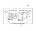
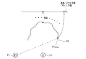
On the other hand, the X-ray extraoral imaging apparatus 1 reconstructs an image of a tomographic plane along a dentition that forms a horseshoe shape of the jaw of the subject by the tomosynthesis method. As shown in FIG. 3, the position of the dentition TR is not located at the geometric center O in the XY plane of the scanning device 10 but is closer to the front side of the jaw. In addition, a cervical vertebra CS as an obstacle at the time of scanning is located behind the dentition TR. Even if the dentition TR itself is taken, there is an overlap of teeth. For this reason, the path | route of the X-ray beam XB is selected for every X-ray irradiation angle (theta) so that the overlap may not be reflected as much as possible, and as much as possible avoids the cervical vertebra CS, and may pass along a dentition. When the path is selected in this way, at each irradiation angle θ, the path takes a value that is orthogonal or close to orthogonal to the dentition TR (note that “orthogonal” means “the X-ray beam passes between the teeth. "I want to do it", not necessarily 90 degrees). For this reason, scanning along such a path is called so-called orthogonal imaging. In consideration of such a viewpoint, the path of the X-ray beam XB is set as shown in FIG. 3, for example.
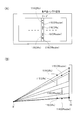
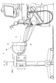
この図3は、本実施形態で採用したX線管31、検出器32、被検体Pの顎部の歯列TR、及び、この歯列TRに沿った3D(3次元)基準断層面SSと、X線ビームXBのパスとのX線照射角度(スキャン角度)θ毎の位置関係をXY面に投影して示す。3D基準断層面SSとは、基準面として採用する断層面が単なる平面ではなく、3次元的な空間の広がりを有しているので、擬似的な3次元という意味で、そのように呼んでいる。また、「X線ビーム」とは、X線管31から曝射され且つコリメータ33でコリメートされたX線である。X線ビームの(パスの)方向(つまりX線照射角度)は、X線管31のX線焦点と検出器31の検出面に入射するX線の中心位置(図3においてXY面に投影した中心位置)とを結ぶラインの方向を言う。X線ビームのパスの位置及び方向は、歯列TRに沿った各位置によって変わるように設定されている。
FIG. 3 shows an X-ray tube 31, a detector 32, a dentition TR of the jaw of the subject P, and a 3D (three-dimensional) reference tomographic plane SS along the dentition TR. The positional relationship for each X-ray irradiation angle (scan angle) θ with the path of the X-ray beam XB is projected onto the XY plane. The 3D reference tomographic plane SS is called as such in the sense of pseudo three-dimensional because the tomographic plane adopted as the reference plane is not a mere plane but has a three-dimensional space spread. . The “X-ray beam” is an X-ray that is emitted from the X-ray tube 31 and collimated by the collimator 33. The (path) direction of the X-ray beam (that is, the X-ray irradiation angle) is the X-ray focal point of the X-ray tube 31 and the center position of the X-ray incident on the detection surface of the detector 31 (projected on the XY plane in FIG. 3). The direction of the line connecting the center position). The position and direction of the X-ray beam path are set so as to vary depending on each position along the tooth row TR.
この歯列TRをXY面に対する投影したときの輪郭(形状)は個人差がある。このため、本実施形態では、統計的に標準的な輪郭を採用している。この標準的な輪郭は、略馬蹄形を成すもので、例えば文献「R. Molteni, “A universal test phantom for dental panoramic radiography” MedicaMudi, vol. 36, no.3, 1991」によっても知られている。この輪郭に沿って3D基準断層面SSが設定されている。この3D基準断層面SSは、図示した位置からZ軸方向に沿って立ち上がる擬似的な3次元な広がりを有する断面(仮想面)である。この3D基準断層面SSは、本実施形態では、装置側で予め用意されているものである。なお、3D基準断層面SSは、装置側で予め用意された複数の断層面から撮影前に選択するようにしてもよい。つまり、3D基準断層面SSとしての固定した断面であることには変わりは無いが、かかる選択動作によって、3D基準断層面SSの位置を、歯列の奥行き(前後)方向の一定範囲で変更可能にしてもよい。
The contour (shape) when this dentition TR is projected onto the XY plane has individual differences. For this reason, in the present embodiment, a statistically standard contour is adopted. This standard contour is substantially horseshoe-shaped, and is also known, for example, from the document “R. Molteni,“ A universal test phantom for dental panoramic radiography ”MedicaMudi, vol. 36, no.3, 1991”. A 3D reference tomographic plane SS is set along this contour. The 3D reference tomographic plane SS is a cross-section (virtual plane) having a pseudo three-dimensional expansion that rises along the Z-axis direction from the illustrated position. In the present embodiment, the 3D reference tomographic plane SS is prepared in advance on the apparatus side. The 3D reference tomographic plane SS may be selected from a plurality of tomographic planes prepared in advance on the apparatus side before imaging. That is, although it is a fixed cross section as the 3D reference tomographic plane SS, the position of the 3D reference tomographic plane SS can be changed within a certain range in the depth (front-rear) direction of the dentition by such a selection operation. It may be.
このような統計的に標準的な歯列TRを採用し、図3に示すように、歯列TRのどの位置を採ってもX線ビームXBのパスが極力、その輪郭に直交するように、且つ、X線ビームXBのパスが極力、頸椎を避けて通過するように、各X線照射角度θにおけるパスの方向(すなわちX線照射方向)が設定される。本実施形態は、そのような歯の重なりやノイズ成分としての頸椎の影響を回避することを優先したX線ビームXBのパスを設定している。このX線照射角度θは、X線管ユニット31U及び検出器ユニット32Uからみれば、回転角度に相当する。このため、この角度θは、回転角度でもあり、X線照射角度でもあり、またスキャン角度でもある。以下、必要に応じて、この角度θを使い分ける。
Employing such a statistically standard dentition TR, as shown in FIG. 3, so that the path of the X-ray beam XB is orthogonal to the contour as much as possible regardless of the position of the dentition TR, In addition, the path direction (that is, the X-ray irradiation direction) at each X-ray irradiation angle θ is set so that the path of the X-ray beam XB passes through the cervical spine as much as possible. In the present embodiment, the path of the X-ray beam XB is set with priority given to avoiding the influence of the tooth overlap and the cervical spine as a noise component. The X-ray irradiation angle θ corresponds to a rotation angle when viewed from the X-ray tube unit 31U and the detector unit 32U. For this reason, this angle θ is also a rotation angle, an X-ray irradiation angle, and a scan angle. Hereinafter, this angle θ is properly used as necessary.
なお、この図3に示す直交撮影を重視したX線ビームXBのパスの設定法は、所望のパス位置の設定ということの代表であり、必ずしも、歯列の各位置においてX線ビームXBのパスが正確に歯列に直交するという意味ではないし、また、上述の直交撮影以外の撮影に対するパスの設定を排除するという意味ではない。
Note that the X-ray beam XB path setting method that emphasizes orthogonal imaging shown in FIG. 3 is representative of setting a desired path position, and the path of the X-ray beam XB is not necessarily set at each position of the dentition. Does not mean that it is exactly orthogonal to the dentition, and does not mean that the setting of a path for photographing other than the above-described orthogonal photographing is excluded.
上述のように直交撮影を所望してX線ビームXBのパスを設定すると、図3から分かるように、歯列TRの前歯部の中心位置ではX線管31(コリメータ33)と検出器32は互いに正対している。つまり、X線ビームXBのパスはリング体12の幾何学的な中心Oを通る。しかし、前歯の中心の位置から左右の臼歯部の方向にX線ビームXBのパスが移動するにつれて、そのパスは幾何学的中心Oから外れた軌道を通る。さらに、臼歯部の奥に進むにつれて、そのパスは中心Oに接近するように移動する。そして、本実施形態の場合、このパスは再び中心Oを通過する。X線ビームXBのパスがどの程度まで移動するかは、スキャン範囲Φ(例えば、Φ=190~210°=±85°~±105°)の設定による。
As described above, when the X-ray beam XB path is set with the desire for orthogonal imaging, the X-ray tube 31 (collimator 33) and the detector 32 are located at the center position of the front tooth portion of the dentition TR, as can be seen from FIG. Facing each other. That is, the path of the X-ray beam XB passes through the geometric center O of the ring body 12. However, as the path of the X-ray beam XB moves from the center position of the front tooth toward the left and right molar parts, the path passes along a trajectory deviating from the geometric center O. Furthermore, the path moves so as to approach the center O as it proceeds to the back of the molar part. In the present embodiment, this path passes through the center O again. The extent to which the path of the X-ray beam XB moves depends on the setting of the scan range Φ (for example, Φ = 190 to 210 ° = ± 85 ° to ± 105 °).
このように、本実施形態では、X線ビームXBのパスを、幾何学的な中心Oよりも撮影対象である歯列TRの形状を優先させ、「直交撮影」ができるように設定されていることにも特徴がある。これを実現するための措置として、X線管31(及びコリメータ33)及び検出器32を互いに円軌道OBに沿って互いに独立して回転可能にし、且つ、コリメータ33をX線管11に対して移動可能に構成している。
As described above, in this embodiment, the path of the X-ray beam XB is set so that “orthogonal imaging” can be performed by giving priority to the shape of the dentition TR to be imaged over the geometric center O. There is also a feature. As measures for realizing this, the X-ray tube 31 (and the collimator 33) and the detector 32 can be rotated independently of each other along the circular orbit OB, and the collimator 33 is moved with respect to the X-ray tube 11. It is configured to be movable.
<濃度ムラ対策>
しかしながら、上述の構成を実施すると、X線強度が低いので、検出器32に入射する単位時間当たりのフォトン数が少なくなる。このため、既存のトモシンセス法で画像を再構成すると、画素濃度が低いことから、ノイズの影響も大きく、また濃度ムラも大きい。
<Countermeasures against uneven density>
However, if the above-described configuration is implemented, the X-ray intensity is low, so the number of photons per unit time incident on the detector 32 is reduced. For this reason, when an image is reconstructed by the existing tomosynthesis method, since the pixel density is low, the influence of noise is large and density unevenness is also large.
・独自の画像再構成
そこで、本実施形態では、照射するX線強度を下げた場合でも、耐ノイズ性も高く、構造物の実際の大きさや形状を反映した高精細な3次元的広がりを持つ画像(3次元的画像)を提供可能な画像再構成法をも併せて採用する。この画像再構成法を実施した処理は後述される。
-Original image reconstruction Therefore, in this embodiment, even when the X-ray intensity to be irradiated is lowered, the noise resistance is high, and it has a high-definition three-dimensional spread reflecting the actual size and shape of the structure. An image reconstruction method capable of providing an image (three-dimensional image) is also employed. Processing that implements this image reconstruction method will be described later.
・拡大率の変化に対する対策
一方、歯列TRがリング体12の幾何学的中心Oに位置していないこと、X線管31及び検出器32を円形軌道OBに沿って動かし、且つ、直交撮影の撮影を優先していることによって、X線照射角度θの値毎に、歯列TRとX線管31との間の距離が大きく変化する。つまり、歯列をスキャンしたときの拡大率がX線照射角度θ毎に変わる。拡大率とは、歯の実際の大きさとその歯の陰影が検出器32の検出面に作る投影像の大きさとの比である。これを、図4を使って説明する。このため、上述した画像処理法は、この拡大率の影響を排除又は低減する処理をも含む。これは、画像再構成の全体処理と伴に後述される。
Measures against change in enlargement ratio On the other hand, the dentition TR is not positioned at the geometric center O of the ring body 12, the X-ray tube 31 and the detector 32 are moved along the circular orbit OB, and orthogonal imaging is performed. By giving priority to the imaging, the distance between the dentition TR and the X-ray tube 31 changes greatly for each value of the X-ray irradiation angle θ. That is, the enlargement ratio when the dentition is scanned changes for each X-ray irradiation angle θ. The enlargement ratio is the ratio between the actual size of the tooth and the size of the projected image formed on the detection surface of the detector 32 by the shadow of the tooth. This will be described with reference to FIG. For this reason, the image processing method described above also includes processing for eliminating or reducing the influence of the enlargement ratio. This will be described later together with the overall image reconstruction process.
・管電流の調整
さらに、本実施形態に係るX線口外撮影装置では、X線管31及び検出器32は幾何学的な中心O(固定)を持つ円形軌道OBに沿って互いに独立して回転(移動)するものの、前述したように直交撮影に重きを置いていることから、回転角度θの夫々の位置におけるX線ビームXBのパスは必ずしも幾何学中心Oを通過していない。幾何学的中心Oを通過していないというよりも、直交撮影を優先して、幾何学中心Oに囚われずにX線ビームXBのパスを設定している、と言える。幾何学中心Oを通過しているX線ビームXBのパスは1回のスキャンの間で前歯の中心部の1点を通過するパスと、左右それぞれの臼歯部の1点を通過する、合計3箇所に過ぎない(図3参照)。
-Adjustment of tube current Furthermore, in the X-ray extraoral imaging apparatus according to this embodiment, the X-ray tube 31 and the detector 32 rotate independently of each other along a circular orbit OB having a geometric center O (fixed). Although (moving), since the emphasis is placed on orthogonal imaging as described above, the path of the X-ray beam XB at each position of the rotation angle θ does not necessarily pass through the geometric center O. It can be said that the path of the X-ray beam XB is set without being trapped by the geometric center O by giving priority to orthogonal imaging rather than passing through the geometric center O. The path of the X-ray beam XB passing through the geometric center O passes through one point in the central part of the anterior tooth and one point in each of the left and right molar parts during a single scan. It is only a place (see FIG. 3).
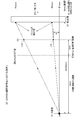
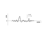
このようなスキャンを実現するために、軌道OBを移動する検出器32の回転角速度Vθが軌道OB上の位置に応じて制御される。このため、例えば図5に示す如く、検出器32がある角度範囲A(臼歯部の一部)を通過するときの回転角速度VθAは、別の角度範囲B(前歯部の一部)を通過する回転角速度VθBよりも大きい。この検出器32の移動中に、X線ビームXBは一定間隔で入射する。このことは、検出器32に入射するX線のフォトン数が軌道OBの位置に応じて変化することを意味する。フォトン数が変化すると、再構成されるパノラマ画像の画素値にムラ(濃度ムラ)が生じて画質が低下する。そこで、この画素値のムラを排除又は抑制するために、検出器32の軌道OB上の回転位置、すなわち、その相手方のX線管31の軌道OB上の回転位置に応じて、その管電流Iを調整するのである。図5の例で言えば、軌道OB上の角度範囲Aに対向する角度範囲A´を移動するときのX線管31の管電流IAを、別の角度範囲Bに対向する角度範囲B´を移動する管電流IBよりも相対的に下げる。これをX線管21の回転角度θの全体に展開すると、回転角度θ対管電流Iの特性は一般的には図6のように表される。つまり、左右の臼歯部をスキャンするときには、前歯部をスキャンするときよりも、管電流Iの値を上げる。なお、管電流Iの最大値は、前述した別室(放射線撮影室)を要求しない値に設定されている。この図8に示す管電流Iの補正特性が予め、後述するROMのルックアップテーブルに予め格納されている。この管電流IのX線照射角度毎の制御も実施される。
In order to realize such a scan, the rotational angular velocity Vθ of the detector 32 moving on the track OB is controlled according to the position on the track OB. Therefore, for example, as shown in FIG. 5, the rotational angular velocity Vθ A when the detector 32 passes through a certain angle range A (part of the molar portion) passes through another angle range B (part of the front tooth portion). greater than the rotational angular speed V [theta] B to. During the movement of the detector 32, the X-ray beam XB is incident at regular intervals. This means that the number of photons of X-rays incident on the detector 32 changes according to the position of the orbit OB. When the number of photons changes, unevenness (density unevenness) occurs in the pixel values of the reconstructed panoramic image, and the image quality deteriorates. Therefore, in order to eliminate or suppress this pixel value unevenness, the tube current I depends on the rotational position of the detector 32 on the trajectory OB, that is, the rotational position of the counterpart X-ray tube 31 on the trajectory OB. Is adjusted. In the example of FIG. 5, the angle range facing the tube current I A of the X-ray tube 31 when moving the angular range A'facing the angular range A in orbit OB, the different angle ranges B B' Is relatively lower than the tube current I B that moves. When this is developed over the entire rotation angle θ of the X-ray tube 21, the characteristic of the rotation angle θ versus the tube current I is generally expressed as shown in FIG. That is, when scanning the left and right molar parts, the value of the tube current I is increased compared to when scanning the front tooth part. The maximum value of the tube current I is set to a value that does not require the above-described separate room (radiation imaging room). The correction characteristic of the tube current I shown in FIG. 8 is stored in advance in a ROM lookup table described later. The tube current I is also controlled for each X-ray irradiation angle.
なお、図3に示すように、極力、頸椎を避けつつ、且つ、所望のスキャン角度θを採る撮影になるようにX線ビームXBのパスを設定しているが、頸椎を完全に避けてパスを設定することは困難である。どうしても、頸椎を通るX線ビームXBのパスが含まれてしまう。そこで、頸椎を通過するパスに沿ってX線ビームが照射されるときには、その分、X線強度を上げるように管電流Iを制御してもよい。
As shown in FIG. 3, the path of the X-ray beam XB is set so as to capture the desired scan angle θ while avoiding the cervical spine as much as possible. Is difficult to set. Inevitably, the path of the X-ray beam XB through the cervical spine is included. Therefore, when the X-ray beam is irradiated along the path passing through the cervical spine, the tube current I may be controlled so as to increase the X-ray intensity accordingly.
なお、上述したような管電流を調整する方法に変えて、又は、一緒に、X線管21に印加する管電圧を調整してもよい。管電圧を上げると、X線のフォトン数が増え、一方、それを下げると、フォトン数が下がるので、管電流の上下と同様の調整機能を発揮することができる。
Note that the tube voltage applied to the X-ray tube 21 may be adjusted instead of or together with the method for adjusting the tube current as described above. When the tube voltage is increased, the number of X-ray photons increases. On the other hand, when the tube voltage is decreased, the number of photons decreases, so that the same adjustment function as that of the tube current can be exhibited.
・データ収集時間の調整
さらに、この管電流Iの制御に代えて又は一緒に、X線透過データの収集時間を制御してもよい。この概念を、図7~10を用いて説明する。
-Adjustment of data acquisition time Furthermore, instead of or together with the control of the tube current I, the acquisition time of X-ray transmission data may be controlled. This concept will be described with reference to FIGS.
本実施形態の場合、図7に示すように、所定時間Tiの経過を想定すると、この時間の間に、X線管31は軌道OBに沿ってxiの距離を移動し、検出器32は同じく軌道OBに沿ってdiの距離だけ移動する。このため、データ収集時間の調整として、この所定時間Tiの値を、検出器32におけるフォトン数のカウントが大体同じになるように決めればよい。
In the case of the present embodiment, as shown in FIG. 7, assuming that a predetermined time Ti has elapsed, during this time, the X-ray tube 31 moves a distance xi along the trajectory OB, and the detector 32 is also the same. It moves by a distance of di along the trajectory OB. For this reason, as the adjustment of the data collection time, the value of the predetermined time Ti may be determined so that the count of the number of photons in the detector 32 is substantially the same.
仮に、頸椎などの障害陰影が無いとすれば、単純に、X線管31と検出器32の移動(回転)に伴う歯列TRに沿った移動距離Siに反比例した速度で両者を移動させ、
ΣC/Si=ΣTi=全体の収集時間(ここで、Cは定数)
となるようにX線管31及び検出器32の移動を制御すればよい。この様子を図8に示す。
If there is no obstacle shadow such as cervical spine, simply move both at a speed inversely proportional to the moving distance Si along the tooth row TR accompanying the movement (rotation) of the X-ray tube 31 and the detector 32,
ΣC / Si = ΣTi = total collection time (where C is a constant)
The movement of the X-ray tube 31 and the detector 32 may be controlled so that This is shown in FIG.
しかしながら、実際には、図9に例示される、頸椎や反対側の顎骨で吸収されるファクタAi(1以下の定数)を考慮する必要がある。そのため、
ΣC/(Si・Ai)=ΣTi=全体の収集時間
となるように、X線管31と検出器32の移動(回転)を制御する。この制御の一例を図10に示す。これにより、パノラマ画像の横方向(つまり、X線ビームXBをスキャンさせる方向)の濃度が一定値に近づく。なお、この濃度ムラの調整とともに、前述したように、パノラマ画像の縦方向における拡大率の補正を行なうことが望ましい。
However, in practice, it is necessary to consider the factor Ai (constant of 1 or less) absorbed in the cervical vertebra and the opposite jawbone as exemplified in FIG. for that reason,
The movement (rotation) of the X-ray tube 31 and the detector 32 is controlled so that ΣC / (Si · Ai) = ΣTi = total acquisition time. An example of this control is shown in FIG. As a result, the density of the panoramic image in the horizontal direction (that is, the direction in which the X-ray beam XB is scanned) approaches a constant value. In addition to the adjustment of the density unevenness, it is desirable to correct the enlargement ratio in the vertical direction of the panoramic image as described above.
なお、画像の濃度ムラを改善する手法として、管電流を変える、管電圧を変える、及び、データ収集時間を変える、という3つの手法を説明したが、これらの3つの手法は適宜に組み合わせて(例えば3つの手法、2つの手法)実施してもよいし、何れか1つを単独で実施してもよい。
Although three methods of changing the tube current, changing the tube voltage, and changing the data collection time have been described as methods for improving the density unevenness of the image, these three methods are appropriately combined ( For example, three methods and two methods) may be performed, or any one of them may be performed alone.
<コリメータの独立制御>
本実施形態では、さらに、コリメータ33の位置及び姿勢が制御されることも1つの特徴である。この趣旨を以下に説明する。
<Independent control of collimator>
In the present embodiment, it is also one feature that the position and orientation of the collimator 33 are controlled. This will be described below.
本実施形態では、コリメータ33の位置及び姿勢も、前述したようにX線管31と検出器32とを結ぶライン、すなわちX線照射方向に応じて制御される。コリメータ33の位置とは、図11(A)に模式的に示すように、コリメータ33のX線管31に対する、X線ビームXBの方向に直交する、XY面に沿った方向の位置を言う。また、コリメータ33の姿勢とは、同図(B)に模式的に示すように、X線ビームXBに対する回転した姿勢を言う。
In this embodiment, the position and orientation of the collimator 33 are also controlled according to the line connecting the X-ray tube 31 and the detector 32, that is, the X-ray irradiation direction as described above. As schematically shown in FIG. 11A, the position of the collimator 33 refers to the position along the XY plane perpendicular to the direction of the X-ray beam XB with respect to the X-ray tube 31 of the collimator 33. Moreover, the attitude | position of the collimator 33 means the attitude | position rotated with respect to the X-ray beam XB, as typically shown to the same figure (B).
このようにコリメータ33の位置及び姿勢を制御する理由は、本実施形態におけるスキャン法が前述したパノラマ撮影を円形軌道にて実現することに基づき検出器とX線管の位置が必ずしも常に対向位置にはないことに拠る。本実施形態におけるスキャン法が前述した直交撮影に基づくものであることに拠る。X線管31と検出器32が常に正対していれば、コリメータ23の位置及び姿勢は固定状態でよい。しかしながら、図3から分かるように、歯列TRの前歯部の中心及び左右の臼歯部側の各一点を除く、大部分の回転角度θの位置で、検出器32がX線管31に対して斜めの方向に位置付けられる。つまりX線管31の正面方向Pからシフトした位置に検出器22が移動するため、この検出器32の検出面に正確にX線ビームXBを入射させるには、コリメータ33の位置及び/又は姿勢を適宜に制御する必要がある。
The reason why the position and orientation of the collimator 33 are controlled in this way is that the position of the detector and the X-ray tube is not always opposite because the scanning method in the present embodiment realizes the panoramic imaging described above in a circular orbit. It depends on not. This is based on the fact that the scanning method in the present embodiment is based on the above-described orthogonal imaging. If the X-ray tube 31 and the detector 32 are always facing each other, the position and posture of the collimator 23 may be fixed. However, as can be seen from FIG. 3, the detector 32 is positioned relative to the X-ray tube 31 at most rotation angle θ positions except for the center of the front tooth portion of the dentition TR and each point on the left and right molar portions. Positioned in an oblique direction. That is, since the detector 22 moves to a position shifted from the front direction P of the X-ray tube 31, the position and / or orientation of the collimator 33 is required to accurately make the X-ray beam XB incident on the detection surface of the detector 32. Need to be controlled appropriately.
なお、コリメータ33はその位置及び姿勢の一方のみを、便宜的に、X線管21の回転角度θに応じて制御するようにしてもよい。
Note that the collimator 33 may control only one of the position and orientation according to the rotation angle θ of the X-ray tube 21 for convenience.
<その他>
さらに、本実施形態に係るスキャン装置10には、X線管31及び検出器32の回転位置を検出する回転センサ36,37、及び、被検体Pの顎部がスキャンに動いたことを検知する動きセンサ38を備えている。回転センサ36,37は、コントローラが指令するモータ駆動用のパルス信号のパルス数から演算により求めるようにしてもよい。
<Others>
Furthermore, the scanning apparatus 10 according to the present embodiment detects that the rotation sensors 36 and 37 that detect the rotational positions of the X-ray tube 31 and the detector 32 and the jaw of the subject P have moved to scan. A motion sensor 38 is provided. The rotation sensors 36 and 37 may be obtained by calculation from the number of pulses of the motor driving pulse signal instructed by the controller.
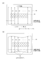
さらに、後述するROM56のLUTには、図12(A)、(B)に示すように、横軸を回転角度θとし且つ縦軸を回転角速度Vθとする回転制御パターンが参照関数として予め格納されている。この回転制御パターンは、前述した図3に示すように、所謂「直交撮影」を達成し且つパノラマ画像の横方向の濃度ムラを低減する上で必要な、X線管31、検出器32、及び被検体Pの顎部の歯列TRの位置関係を回転角度θ毎に規定する参照関数である。この参照関数は、したがって、直交撮影に必要な速度制御ファクタに加え、前述した濃度ムラ対策のうちの、管電流の調整ファクタ及びデータ収集時間の調整ファクタのうちの少なくとも何れか一方のファクタに基づいて予め規定されている。
Furthermore, as shown in FIGS. 12A and 12B, a rotation control pattern in which the horizontal axis is the rotation angle θ and the vertical axis is the rotation angular velocity V θ is stored in advance in the LUT of the ROM 56 described later as a reference function. Has been. As shown in FIG. 3 described above, this rotation control pattern is an X-ray tube 31, a detector 32, and a detector that are necessary for achieving so-called “orthogonal imaging” and reducing lateral density unevenness of a panoramic image. This is a reference function that defines the positional relationship of the dentition TR of the jaw of the subject P for each rotation angle θ. Therefore, the reference function is based on at least one of the tube current adjustment factor and the data collection time adjustment factor among the above-described density unevenness countermeasures in addition to the speed control factor necessary for orthogonal imaging. Are prescribed in advance.
図12(A)は、X線管31が採るべき回転角度θ毎の回転角速度Vθを定めている。この回転角度θ-回転角速度Vθを規定するグラフによれば、回転角度θ=0°の位置で回転角速度Vθが高く、回転角度θ=0°から左右に角度が増加するにつれて回転角速度Vθが下がるように設定されている。なお、回転角度θ=0°の位置は基準位置として、前述した図3から分かる。すなわち、本実施形態では、円形軌道OB内に位置する歯列TRに沿って3D基準断層面SS(図3ではZ軸方向から見ている)を設定している。この3D基準断層面SSに対して歯列TRの前歯部の中心をX線ビームXBが通るときに、そのX線ビームXBは円形軌道OBの幾何学的中心Oを通るように設定されている。そこで、前歯部の中心及び幾何学的中心Oを通るラインの回転角度θをθ=0°に定めている。
FIG. 12A defines the rotational angular velocity V θ for each rotational angle θ that the X-ray tube 31 should take. According to the graph to define the rotation angle θ- rotational angular velocity V theta, rotational angular speed V as the rotation angle theta = 0 ° rotational angular speed V theta at the position of the high angle is increased from the rotation angle theta = 0 ° to the left and right It is set so that θ decreases. Note that the position at the rotation angle θ = 0 ° is known from FIG. 3 as the reference position. That is, in this embodiment, the 3D reference tomographic plane SS (viewed from the Z-axis direction in FIG. 3) is set along the tooth row TR located in the circular orbit OB. When the X-ray beam XB passes through the center of the front tooth portion of the dentition TR with respect to the 3D reference tomographic plane SS, the X-ray beam XB is set to pass through the geometric center O of the circular orbit OB. . Therefore, the rotation angle θ of the line passing through the center of the front tooth portion and the geometric center O is set to θ = 0 °.
これに対し、図12(B)は、検出器32が採るべき回転角度θ毎の回転角速度Vθを定めている。この回転角度θ-回転角速度Vθを規定するグラフは、その大小の関係が上述した同図(A)のものとは反対又はそれに近い軌跡を描くように設定されている。
On the other hand, FIG. 12B defines a rotational angular velocity V θ for each rotational angle θ that the detector 32 should take. The graph that defines the rotation angle θ−the rotation angular velocity V θ is set so that the magnitude relationship draws a trajectory opposite or close to that of FIG.
<スキャン>
さらに、本実施形態に係るX線口外撮影装置1において実施される、顎の角度をチェックするためのプリスキャン、及び、データ収集のためのメインスキャンについて説明する。
<Scan>
Furthermore, a pre-scan for checking the jaw angle and a main scan for data collection performed in the X-ray extraoral imaging apparatus 1 according to the present embodiment will be described.
・プリスキャン
このX線口外撮影装置1では、1回のスキャンに伴う患者に対するX線被曝の量が少ないので、実際の診療のための画像データ(フレームデータ)を収集するメインスキャンに先立ってプリスキャンを実施する。プリスキャンを実施した場合でも、患者のX線被曝量を低く抑えることができる。プリスキャンは、画素サイズを荒くして、電流を下げ、かつ高速にデータ収集を行うものである。
Pre-scan In this X-ray extraoral imaging apparatus 1, since the amount of X-ray exposure to the patient in one scan is small, the pre-scan is performed prior to the main scan to collect image data (frame data) for actual medical treatment. Perform a scan. Even when pre-scanning is performed, the patient's X-ray exposure can be kept low. Pre-scanning is a method of collecting data at a high speed by reducing the current by reducing the pixel size.
このプリスキャンの手順を図13に示す。
This pre-scan procedure is shown in FIG.
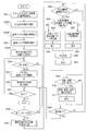
患者の顔、すなわち顎部の周囲にスキャン装置10をセットする。これにより、患者の顎の周囲に近接するような状態でリング体11が位置付けられる。この状態で、コントローラ55による制御が開始される。
¡Set the scanning device 10 around the patient's face, that is, around the jaw. Thereby, the ring body 11 is positioned in a state of being close to the periphery of the patient's jaw. In this state, control by the controller 55 is started.
このプリスキャンが開始されると、コントローラ55はまず、ステップS1にて、位置検出器36及び37から位置情報を読み込み、X線管31及び検出器32の軌道OB上の位置を演算する。次いで、コントローラ55は、ステップS2にて、この演算した位置が初期位置か否かを判断し、初期位置でなければ、その処理をステップS3に移行させる。ステップS3にて、モータ42及び52を回転させてX線管31及び検出器32を軌道OB上の予め設定されている初期位置に復帰させる。なお、この場合、コリメータ33のX線管31に対する位置及び姿勢は所定位置で固定されている。
When this pre-scan is started, the controller 55 first reads position information from the position detectors 36 and 37 in step S1, and calculates the positions of the X-ray tube 31 and the detector 32 on the trajectory OB. Next, in step S2, the controller 55 determines whether or not the calculated position is an initial position. If the calculated position is not the initial position, the process proceeds to step S3. In step S3, the motors 42 and 52 are rotated to return the X-ray tube 31 and the detector 32 to the preset initial positions on the orbit OB. In this case, the position and posture of the collimator 33 with respect to the X-ray tube 31 are fixed at a predetermined position.
一方、ステップS2の判断においてX線管31及び検出器32が既に軌道OB上の初期位置に在る場合、コントローラ55は、ステップ4にて操作器61から送信されてくるオペレータの操作信号を監視しながら、プリスキャンを開始するか否か判断しながら待機する。
On the other hand, if the X-ray tube 31 and the detector 32 are already in the initial positions on the orbit OB in the determination in step S2, the controller 55 monitors the operation signal of the operator transmitted from the operation device 61 in step 4. While waiting, it is determined whether or not to start pre-scanning.
このステップS4の判断がYES、すなわちオペレータがスキャンの開始を指令した場合、コントローラ55は、その処理をステップS5に移行させ、プリスキャン条件をROM56のLUTから読み出し、プリスキャンを実行させる。このプリスキャン条件には、X線管31の曝射条件(管電圧、管電流)、スキャン速度(X線管31、検出器32の回転速度)、及び、画像処理における画素の束ね数が含まれる。例えば、後述するメインスキャンに比べて、管電流を1/2に、スキャン速度を2倍に、画素の束ね数=4とするプリンスキャン条件が読み出される。
If the determination in step S4 is YES, that is, if the operator commands the start of scanning, the controller 55 shifts the process to step S5, reads the prescan condition from the LUT in the ROM 56, and executes the prescan. The pre-scan conditions include the exposure conditions (tube voltage and tube current) of the X-ray tube 31, the scanning speed (rotational speed of the X-ray tube 31 and the detector 32), and the number of pixels bundled in image processing. It is. For example, a print scan condition in which the tube current is halved, the scan speed is doubled, and the number of pixel bundles = 4 is read compared to a main scan described later.
なお、プリスキャンの場合、その目的に鑑みると、読影可能であるかぎり粗い画素の2次元パノラマ画像又は3次元の断層像(3次元パノラマ画像)の生成が許される。そのため、本実施形態では、プリスキャン条件としては、上述したようにスキャン速度を上げ、且つ、管電流を下げること以外の条件は、後述するメインスキャンと同様に実行する。つまり、後述するように、管電流の補正、コリメータの姿勢・位置制御、及び、スキャン範囲(回転角度θの範囲)=例えば210°、実在位置を考慮した自動焦点化の3次元画像処理法(後述する)を設定している。
In the case of pre-scanning, in view of the purpose, it is allowed to generate a two-dimensional panoramic image or a three-dimensional tomographic image (three-dimensional panoramic image) of coarse pixels as long as interpretation is possible. Therefore, in the present embodiment, as the pre-scan conditions, conditions other than increasing the scan speed and decreasing the tube current as described above are executed in the same manner as the main scan described later. That is, as will be described later, correction of tube current, attitude / position control of the collimator, and scan range (range of rotation angle θ) = 210 °, for example, autofocusing three-dimensional image processing method considering the actual position ( (To be described later).
しかしながら、プリスキャン条件は必ずしもメインスキャンのスキャン条件と同じでなくてもよく、従来公知の種々のパノラマ画像の処理法を設定するようにしてもよい。
However, the prescan conditions are not necessarily the same as the main scan conditions, and various conventionally known panoramic image processing methods may be set.
コントローラ55は、ステップS6にて、再び、位置検出器36及び37から回転位置情報を読み込み、X線管31及び検出器32の軌道OB上に沿った現在の回転位置を演算する。次いで、コントローラ55は、ステップS7にて、この回転位置に基づき、スキャンが終了したか否かを判断する。つまり、X線管31及び検出器32が共に軌道OB上に沿って、設定した回転角度(例えば210°)の間を移動しながらスキャンを行ない、予め定めた回転位置の終点まで到達したか否かを判断する。
In step S6, the controller 55 again reads the rotational position information from the position detectors 36 and 37, and calculates the current rotational position along the trajectory OB of the X-ray tube 31 and the detector 32. Next, in step S7, the controller 55 determines whether or not the scan is completed based on this rotational position. That is, whether or not the X-ray tube 31 and the detector 32 have both moved along a trajectory OB while moving within a set rotation angle (for example, 210 °) and have reached the end point of a predetermined rotation position. Determine whether.
このステップS7の判断がYES、すなわち終点到達を示す場合、コントローラ55は、前述した同様にステップS8、S9にてX線管31及び検出器32を、それらの軌道OB上の初期位置に戻して、スキャン制御を終わる。
If the determination in step S7 is YES, that is, the end point has been reached, the controller 55 returns the X-ray tube 31 and the detector 32 to their initial positions on the trajectory OB in steps S8 and S9 in the same manner as described above. End scanning control.
これに対して、ステップS7にてNO、すなわちX線管31及び検出器32が未だそれらの終点位置に到達していない場合、その処理をステップS6に戻して繰り返す。
On the other hand, if NO in step S7, that is, if the X-ray tube 31 and the detector 32 have not yet reached their end points, the process returns to step S6 and is repeated.
画像プロセッサ54は、このように収集されたプリスキャンのフレームデータに、後述するメインスキャン時のトモシンセス法を適用する。これにより、後述するが、メインスキャン時と同様に、対象物の空間的な実在位置を考慮し、常にX線管の焦点を睨む向きに沿って自動的に最適焦点化した3次元(擬似的3次元)のパノラマ画像を再構成する。この再構成された3次元パノラマ画像は、画像上のそれぞれの位置にて、隣接する4つの画素を1つに束ねてパノラマ画像が形成される。このパノラマ画像のサイズは縮小されており、粗い画質であるが、歯列TRなどの位置確認用としては充分である。X線量は、スキャン速度を2倍にし、管電流は1/2にするので、トータルでX線量は1/4になる。これにより、X線被曝量も少なくなる。
The image processor 54 applies the tomosynthesis method at the time of main scanning, which will be described later, to the prescan frame data collected in this way. As described later, as described later, in the same way as in the main scan, the three-dimensional (pseudo-pseudo) that is automatically optimally focused along the direction in which the focus of the X-ray tube is always taken in consideration of the spatial actual position of the object. Reconstruct a 3D panoramic image. The reconstructed three-dimensional panoramic image is formed by bundling four adjacent pixels into one at each position on the image. The panoramic image is reduced in size and has a rough image quality, but it is sufficient for position confirmation of the tooth row TR and the like. Since the X-ray dose doubles the scanning speed and the tube current becomes 1/2, the total X-ray dose becomes 1/4. Thereby, X-ray exposure amount also decreases.
オペレータは、この再構成された3次元のパノラマ画像を観察して、歯列TRを的確に捉えているか、顎(首)の角度が的確かなどの確認を行う。必要であれば、顎部の位置付けを修正する。また、このパノラマ画像には頸椎CSが写りこんでいるので、背後に回ったときのX線管31からのX線ビームができるだけ頸椎CSの間を通過し良好な画像になるように、顎(首)の角度も修正する。
The operator observes the reconstructed three-dimensional panoramic image and confirms whether or not the dentition TR is accurately captured or the angle of the jaw (neck) is accurate. If necessary, correct the jaw positioning. In addition, since the cervical vertebra CS is reflected in this panoramic image, the chin (so that the X-ray beam from the X-ray tube 31 when passing around the back passes as much as possible between the cervical vertebra CS and becomes a good image. Also correct the angle of the neck.
なお、再構成された3次元画像の位置を見て、所望の3次元位置に顎が設定されているかを解析し、顎の位置を自動的に変えるようにチンレストの角度を制御することもできる。なお、従来の再構成法によってパノラマ画像を再構成した場合も、オペレータが、その画像から顎部の位置を判断し、位置の修正を促すことができる。
It is also possible to control the angle of the chin rest so that the jaw position is automatically changed by looking at the position of the reconstructed 3D image and analyzing whether the jaw is set at the desired 3D position. . Even when the panoramic image is reconstructed by the conventional reconstruction method, the operator can determine the position of the jaw from the image and prompt the user to correct the position.
・メインスキャン
次に、図14を参照して、コントローラ55の制御下で実行されるメインスキャンの制御を説明する。
Main Scan Next, the main scan control executed under the control of the controller 55 will be described with reference to FIG.
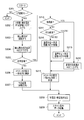
コントローラ55は、予めROM56に格納されていたスキャン制御のためのプログラムをそのワークエリアに読み出し、このプログラムを順次実行する。
The controller 55 reads a scan control program stored in advance in the ROM 56 into the work area and sequentially executes the program.
このプログラムが開始されると、コントローラ55はまず、ステップS11にて、位置検出器36及び37から位置情報を読み込み、X線管31及び検出器32の軌道OB上の位置を演算する。次いで、コントローラ55は、ステップS12にて、この演算した位置が初期位置か否かを判断し、初期位置でなければ、その処理をステップS13に移行させる。ステップS13にて、モータ42及び52を回転させてX線管31及び検出器32を軌道OB上の予め設定されている初期位置に復帰させる。
When this program is started, the controller 55 first reads position information from the position detectors 36 and 37 in step S11, and calculates the positions of the X-ray tube 31 and the detector 32 on the orbit OB. Next, in step S12, the controller 55 determines whether or not the calculated position is an initial position. If the calculated position is not the initial position, the process proceeds to step S13. In step S13, the motors 42 and 52 are rotated to return the X-ray tube 31 and the detector 32 to the preset initial positions on the orbit OB.
一方、ステップS12の判断においてX線管31及び検出器32が既に軌道OB上の初期位置に在る場合、コントローラ55は、ステップ14にて操作器61から送信されてくるオペレータの操作信号を監視しながら、メインスキャンを開始するか否か判断しながら待機する。
On the other hand, when the X-ray tube 31 and the detector 32 are already in the initial positions on the orbit OB in the determination in step S12, the controller 55 monitors the operation signal of the operator transmitted from the operation device 61 in step 14. While waiting, it is determined whether or not to start the main scan.
このステップS14の判断がYES、すなわちオペレータがメインスキャンの開始を指令した場合、コントローラ55は、その処理をステップS15に移行させ、X線管31及び検出器32それぞれの参照関数(回転パターン)をROM56のLUTから読み出し、その参照関数に基づいてメインスキャンを開始させる。この参照関数は、図12(A)、(B)に示すように、横軸を回転位置θとし且つ縦軸を回転角速度Vθである。
If the determination in step S14 is YES, that is, if the operator instructs the start of the main scan, the controller 55 shifts the process to step S15, and sets the reference functions (rotation patterns) of the X-ray tube 31 and the detector 32, respectively. Read from the LUT of the ROM 56 and start the main scan based on the reference function. In this reference function, as shown in FIGS. 12A and 12B, the horizontal axis represents the rotational position θ and the vertical axis represents the rotational angular velocity V θ .
コントローラ55は、ステップS16にて、再び、位置検出器36及び37から回転位置情報を読み込み、X線管31及び検出器32の軌道OB上に沿った現在の回転位置を演算する。次いで、コントローラ55は、ステップS17にて、この回転位置に基づき、スキャンが終了したか否かを判断する。つまり、X線管31及び検出器32が共に軌道OB上に沿って、設定した回転角度(例えば210°)の間を移動しながらスキャンを行ない、予め定めた回転位置の終点まで到達したか否かを判断する。
In step S16, the controller 55 again reads the rotational position information from the position detectors 36 and 37, and calculates the current rotational position along the trajectory OB of the X-ray tube 31 and the detector 32. Next, in step S17, the controller 55 determines whether or not the scan has ended based on this rotational position. That is, whether or not the X-ray tube 31 and the detector 32 have both moved along a trajectory OB while moving within a set rotation angle (for example, 210 °) and have reached the end point of a predetermined rotation position. Determine whether.
このステップS17の判断がYES、すなわち終点到達を示す場合、コントローラ55は、前述した同様にステップS18、S19にてX線管31及び検出器32を、それらの軌道OB上の初期位置に戻して、スキャン制御を終わる。
If the determination in step S17 is YES, that is, the end point has been reached, the controller 55 returns the X-ray tube 31 and the detector 32 to their initial positions on the orbit OB in steps S18 and S19 as described above. End scanning control.
これに対して、ステップS17にてNO、すなわちX線管31及び検出器32が未だそれらの終点位置に到達していない場合、コントローラ55はステップS20の処理に移行する。この処理により、ステップS16で検出したX線管31及び検出器32の現在の回転位置θに応じた回転角速度Vθが演算される。つまり、コントローラ55はROM56のLUTを参照し、図12(A),(B)に示す関数に現在の回転位置θを適用することで、現在指令すべき回転角速度Vθが決められる。
On the other hand, if NO in step S17, that is, if the X-ray tube 31 and the detector 32 have not yet reached their end points, the controller 55 proceeds to the process of step S20. With this process, the rotational angular velocity Vθ corresponding to the current rotational position θ of the X-ray tube 31 and detector 32 detected in step S16 is calculated. That is, the controller 55 refers to the LUT in the ROM 56 and applies the current rotational position θ to the functions shown in FIGS. 12A and 12B, thereby determining the rotational angular velocity V θ to be commanded at present.
次いで、コントローラ55は、ステップS21にて、X線管21に供給する管電流Iを現在の回転位置θに応じて演算する。この演算の意図は、前述したように、検出器22が検出するX線のフォトン数の差を補正することである。なお、前述したようにデータ収集時間で充分に濃度ムラの変化を抑制できる場合には、この管電流Iの調整処理は実行しなくてもよい。
Next, in step S21, the controller 55 calculates the tube current I supplied to the X-ray tube 21 according to the current rotational position θ. The intent of this calculation is to correct the difference in the number of X-ray photons detected by the detector 22 as described above. Note that, as described above, when the change in density unevenness can be sufficiently suppressed in the data collection time, the tube current I adjustment process need not be executed.
さらに、コントローラ55は、そのステップS22にて、前述したステップS20で求めたX線管31及び検出器32の回転角度θを利用して、コリメータ33の位置/姿勢を制御する指令値を演算する。この指令値は、コリメータ33を駆動する駆動部34の駆動信号として演算される。
Further, in step S22, the controller 55 calculates a command value for controlling the position / posture of the collimator 33 using the rotation angle θ of the X-ray tube 31 and the detector 32 obtained in step S20 described above. . This command value is calculated as a drive signal for the drive unit 34 that drives the collimator 33.
このようにX線管31及び検出器32の回転速度V、X線管31の管電流I、並びに、コリメータ33の位置/姿勢の指令値が求められるので、コントローラ55はステップS22にて、それらの値をモータ42、52、34及び高電圧発生装置12に指令する。これにより、X線管31は高電圧発生装置12から所定管電圧V及び演算した管電流Iに応じてパルス駆動信号を受け、この駆動信号に応じた強度及びフォトン数のX線を発生させる。また、モータ42、52の例えばパルス駆動によりX線管31及び検出器32が互いに独立した回転速度で軌道OBに沿って移動(回転)する。さらに、X線管31及び検出器32の各回転位置にて、X線管31から照射されたX線ビームがコリメータ33により検出器32の検出面を正確に方向付けられるようにコリメートされる。この結果、X線ビームXBは常に検出器32の検出面に確実に入射できる。
As described above, the rotational speed V of the X-ray tube 31 and the detector 32, the tube current I of the X-ray tube 31, and the command value of the position / posture of the collimator 33 are obtained. Is given to the motors 42, 52, 34 and the high voltage generator 12. As a result, the X-ray tube 31 receives a pulse drive signal from the high voltage generator 12 according to the predetermined tube voltage V and the calculated tube current I, and generates X-rays having the intensity and the number of photons according to the drive signal. Further, the X-ray tube 31 and the detector 32 move (rotate) along the orbit OB at mutually independent rotational speeds by, for example, pulse driving of the motors 42 and 52. Further, at each rotational position of the X-ray tube 31 and the detector 32, the X-ray beam irradiated from the X-ray tube 31 is collimated by the collimator 33 so that the detection surface of the detector 32 can be accurately directed. As a result, the X-ray beam XB can always reliably enter the detection surface of the detector 32.
その後、コントローラ55の処理はステップS16に戻され、前述したステップS16~S23がスキャン終了及び初期位置への復帰まで繰り返される。
Thereafter, the processing of the controller 55 is returned to step S16, and the above-described steps S16 to S23 are repeated until the scan is completed and the initial position is returned.
したがって、図15(A)に示すように初期位置に在るX線管31及び検出器32(及びコリメータ33)は、その回転駆動の開始に伴って円形軌道OBを移動し始める(図15(B))。この移動を行ないながら、X線管31から一定間隔でX線が照射される。このX線ビームXBのパスは予め定めた直交撮影などに専念したパスとなり、極力、歯列TRに直交するように設定されている。X線管31及び検出器32の移動に伴って、被検体Pの顎部の前側を回るように移動する(図15(C),(D))。この移動中も勿論、一定間隔のX線スキャンが実行される。やがて、X線管31及び検出器32はそれらの回転の終点(すなわち、210°のスキャン終了の位置)まで到達すると(図15(E))、スキャンを終了させて、元の初期位置まで戻る(図15(F))。
Therefore, as shown in FIG. 15A, the X-ray tube 31 and the detector 32 (and the collimator 33) in the initial position start to move on the circular orbit OB with the start of the rotational drive (FIG. B)). While performing this movement, X-rays are emitted from the X-ray tube 31 at regular intervals. The path of the X-ray beam XB is a path dedicated to predetermined orthogonal imaging or the like, and is set to be orthogonal to the dentition TR as much as possible. As the X-ray tube 31 and the detector 32 move, the X-ray tube 31 and the detector 32 move so as to go around the front side of the jaw of the subject P (FIGS. 15C and 15D). Of course, X-ray scans at regular intervals are executed during this movement. Eventually, when the X-ray tube 31 and the detector 32 reach the end point of their rotation (that is, the position at which the scan ends at 210 °) (FIG. 15E), the scan ends and returns to the original initial position. (FIG. 15F).
なお、コントローラ55は、また動きセンサ38の信号を常時監視しており、被検体Pの動きを検出した場合、操作器61又は別途の図示しない非常用スイッチからの指示に応じて、スキャンを中止するとともに、その旨を警告する。これにより、被検体Pがスキャンに驚いて動いたとき、不用意に動いて画質が担保できないときなどに、再撮像を行うことができる。
The controller 55 also constantly monitors the signal of the motion sensor 38, and when the movement of the subject P is detected, the scan is stopped in response to an instruction from the operation device 61 or a separate emergency switch (not shown). And warn of this. As a result, re-imaging can be performed when the subject P moves surprised by the scan, or when the subject P moves carelessly and image quality cannot be guaranteed.
<3D再構成>
一方、患者の顎部の撮像を行う場合は、後述するように、撮像空間ISにおける歯列の実体位置を正確に把握した3D再構成が実行される。これは、図29に概説するように、3D基準断層面SSから、X線管31を睨むX線の斜めの照射方向に沿って投影が行われ、歯列などの撮像対象(実体物)の3次元位置が高精度に同定される。以下、この位置同定の処理を含む撮像を説明する。
<3D reconstruction>
On the other hand, when imaging the patient's jaw, 3D reconstruction is performed that accurately grasps the actual position of the dentition in the imaging space IS, as will be described later. As outlined in FIG. 29, the projection is performed from the 3D reference tomographic plane SS along the oblique irradiation direction of the X-rays sandwiching the X-ray tube 31, and an imaging target (entity) such as a dentition is projected. A three-dimensional position is identified with high accuracy. Hereinafter, imaging including the process of position identification will be described.
・撮像空間を規定するパラメータのキャリブレーション
撮像を説明する前に、ファントムを使った、撮像空間における基準断層面に対する撮像系の3次元構造を示す幾何学的なパラメータの値や変化量を推定する処理、すなわちキャリブレーションを説明する。このキャリブレーションの結果は、画像再構成に反映させられるとともに、必要に応じて、撮像空間の構造解析や設計に用いられる。
・ Calibration of parameters that define the imaging space Before explaining imaging, estimate the values and changes of geometric parameters that indicate the three-dimensional structure of the imaging system relative to the reference tomographic plane in the imaging space using a phantom. Processing, that is, calibration will be described. The result of this calibration is reflected in the image reconstruction, and is used for structural analysis and design of the imaging space as necessary.
このキャリブレーションに伴う処理は、コントローラ57及び画像プロセッサ56が協働して実行される。キャリブレーション専用のプロセッサを設けてもよい。このキャリブレーションには、本実施形態では、被検体Pの歯列を模したファントムを用いることを特徴する。
The processing accompanying this calibration is executed in cooperation with the controller 57 and the image processor 56. A processor dedicated to calibration may be provided. This calibration is characterized in that a phantom that imitates the dentition of the subject P is used in this embodiment.
(ファントム)
図16に、このファントム(ファントム装置)101の一部破断した外観を示す。このファントム101は、かかるキャリブレーションに必要なパラメータの測定を1個で間に合わせることができる万能型ファントムである。なお、本発明に係るファントムは、必ずしも、この万能型ファントムに限定されるものではなく、後述するように3D画像再構成に必要なパラメータをキャリブレーションを実施できるものであれば、その形態は様々に変形可能であることは勿論である。この変形例の幾つかも後に説明される。
(phantom)
FIG. 16 shows a partially broken appearance of the phantom (phantom device) 101. This phantom 101 is a universal phantom capable of measuring parameters necessary for such calibration in one piece. The phantom according to the present invention is not necessarily limited to this all-purpose phantom, and various forms are possible as long as parameters necessary for 3D image reconstruction can be calibrated as will be described later. Of course, it can be deformed. Some of these variations are also described later.
この万能型ファントム101は、透明な樹脂製の板状のベース111及び天板112と、このベース111及び天板112に挟持された複数の支柱113とを備える。これらの支柱113(113´)には、後述するようにX線透過率が樹脂材とは異なる金属製のマーカを備えている。なお、樹脂の種類は例えばアクリル樹脂であるが、X線透過率がマーカのそれと異なるものであればよい。また、樹脂が透明としたのは、マーカが見易いからである。
The universal phantom 101 includes a plate-like base 111 and a top plate 112 made of a transparent resin, and a plurality of support columns 113 sandwiched between the base 111 and the top plate 112. These columns 113 (113 ′) are provided with metal markers having X-ray transmittances different from those of the resin material, as will be described later. In addition, although the kind of resin is an acrylic resin, for example, the X-ray transmittance should just differ from that of a marker. The resin is transparent because the marker is easy to see.
支柱113(113´)のそれぞれは、その上下端がベース111及び天板112に差し込まれて固定されている。以下、これを詳述する。
Each of the pillars 113 (113 ′) is fixed by inserting upper and lower ends thereof into the base 111 and the top plate 112. This will be described in detail below.
ベース111は、図16,17に示すように、四角い板状を成し、透明な樹脂部材で製造される。このベース111の上面には、3次元の基準断層面SSをXY面に投影したときの基準面軌道ORsと、この基準面軌道ORsよりも所定距離DS、例えば20mm外側に当該基準面軌道ORsに例えば平行に引かれた外側面軌道ORouterとが設定されている。これらの軌道ORs, ORouterは、オペレータに分かり易いように、ベース111の面上に実際に線として描出してもよいし、仮想的なものであってもよい。
The base 111 has a square plate shape as shown in FIGS. 16 and 17 and is made of a transparent resin member. On the upper surface of the base 111, the reference plane trajectory ORs when the three-dimensional reference tomographic plane SS is projected onto the XY plane and the reference plane trajectory ORs outside the reference plane trajectory ORs by a predetermined distance DS, for example, 20 mm. For example, an outer surface trajectory ORouter drawn in parallel is set. These orbits ORs and ORouter may be actually drawn as lines on the surface of the base 111 so as to be easily understood by the operator, or may be virtual.
このベース111の上面には、それらの両方の軌道ORs, ORouterと基準断層面SSに焦点が合うようにX線管31及び検出器32を回転移動させるときのX線照射角度θそれぞれとの交点に四角い植設穴111Aが形成される。なお、上記両軌道ORs、ORouter間の距離DSは必ずしも20mmに設定する必要はなく、限られたサイズ関係の中で後述するパラメータをより精度良く演算できる値であればよい。
On the upper surface of the base 111, the intersections of the X-ray irradiation angle θ when the X-ray tube 31 and the detector 32 are rotationally moved so that both the trajectories ORs, ORouter and the reference tomographic plane SS are in focus. A square planting hole 111A is formed. Note that the distance DS between the two orbits ORs and ORouter does not necessarily need to be set to 20 mm, and may be any value that can calculate parameters described later with higher accuracy within a limited size relationship.
複数の支柱113は、それぞれ、図18,19に示すように、アクリルなどの樹脂製の角柱として形成されている。各支柱113は、一定長さの角柱状の支柱本体113Aと、その上下端それぞれに一体に突設された四角柱状の突起113Bとを備える。支柱本体113Aは、その長手方向に直交する断面サイズが例えば5mm×5mmであり、その長さが92mmである。各突起113Bのサイズは、支柱本体113Aのそれよりも小さい断面であって、例えば高さ5mm程度の長さになっている。
The plurality of columns 113 are each formed as a prism made of resin such as acrylic as shown in FIGS. Each column 113 includes a columnar column main body 113A having a fixed length, and a quadrangular columnar projection 113B integrally projecting from the upper and lower ends thereof. 113 A of support | pillar main bodies are the cross-sectional sizes orthogonal to the longitudinal direction, for example, are 5 mm x 5 mm, and the length is 92 mm. The size of each protrusion 113B is a cross section smaller than that of the column main body 113A, and has a length of about 5 mm, for example.
各支柱本体113Aの一面には、キャリブレーション用の第1、第2、及び第3のマーカ114,115、及び116が配設されている。これらのマーカ114,115、及び116は全て、アルミ製又は黄銅製の小径のロッドであり、その径は例えば0.6mmである。このうち、第1及び第2のマーカ114、115は、支柱本体113Aの上端、下端からそれぞれ所定距離、例えば10mm、15mmだけ離れた位置に横向きに配設されている。支柱本体11Aの表面に例えば径0.6mmの断面半円状の削りを入れて、その削り部分に小径ロッドとしての第1及び第2のマーカ114、115を固設する。
1st, 2nd, and 3rd markers 114, 115, and 116 for calibration are arranged on one side of each support body 113A. These markers 114, 115, and 116 are all small rods made of aluminum or brass, and the diameter thereof is, for example, 0.6 mm. Among these, the first and second markers 114 and 115 are disposed laterally at positions separated from the upper end and the lower end of the column main body 113A by a predetermined distance, for example, 10 mm and 15 mm, respectively. For example, a semicircular cross-section with a diameter of 0.6 mm is put on the surface of the column main body 11A, and first and second markers 114 and 115 as small-diameter rods are fixed to the cut portion.
さらに、図18に示すように、第3のマーカ116は、支柱本体113Aの上端から例えば30mm離れた位置を中心に縦方向に沿って固設されている。この第3のマーカ116は一定の長さを有し、その長さは例えば20mmである。この第3のマーカ116は、上述した第1及び第2のマーカ114,115と同様の方法で植設されている。
Furthermore, as shown in FIG. 18, the third marker 116 is fixed along the vertical direction centering on a position 30 mm away from the upper end of the column main body 113A, for example. The third marker 116 has a certain length, and the length is, for example, 20 mm. The third marker 116 is implanted in the same manner as the first and second markers 114 and 115 described above.
なお、上述した支柱113及びマーカ位置の寸法はあくまで例示であって、その他の適宜な寸法で設計することができる。
Note that the dimensions of the support pillar 113 and the marker position described above are merely examples, and can be designed with other appropriate dimensions.
以上、基準面軌道ORsに沿って配設されるファントム113を図16について説明した。
The phantom 113 disposed along the reference plane trajectory ORs has been described with reference to FIG.
一方、外側面軌道ORouterに沿って配設されるファントム113´は、図19に示したように構成されている。ここで興味深い特徴は、図18に示したファントム113を上下逆さまにしたものが図19のファントム113´になっているということである。このため、各ファントム113´にも第2、第1のマーカ115,114が上下端寄りに横向きに位置し、且つ第1のマーカ114寄りの位置で縦向きに位置している。マーカの植設方法も全く同じであるので、ファントム101を組み立てるときに、基準面軌道ORsと外側面軌道ORouterとの間で逆さまに向きを変えればよく、パーツの共通化を図り、製造コストを下げることができる。勿論、互いの逆さまの向きを混同しないようにX線透過に影響を与えない上下端の目印を付けたり、植設用の突起113B及び植設穴111Aの形状を、上下のベース111及び天板112の間で違えるなどの変形を施してもよい。
On the other hand, the phantom 113 ′ disposed along the outer surface track ORouter is configured as shown in FIG. 19. Here, an interesting feature is that the phantom 113 shown in FIG. 18 is turned upside down to form the phantom 113 ′ in FIG. For this reason, the second and first markers 115 and 114 are also positioned laterally near the upper and lower ends in each phantom 113 ′, and are positioned vertically at a position near the first marker 114. Since the marker installation method is exactly the same, when assembling the phantom 101, it is only necessary to change the direction upside down between the reference surface track ORs and the outer surface track ORouter. Can be lowered. Of course, in order not to confuse the upside-down directions, marks on the upper and lower ends that do not affect the X-ray transmission are added, and the shapes of the planting projections 113B and the planting holes 111A are changed to the upper and lower bases 111 and the top plate. Modifications such as a difference between 112 may be made.
上述のように、第1及び第2のマーカ114,115と第3のマーカ116の植設方向及び長さは互いに異なる。その理由は、キャリブレーションにおいて異なるパラメータの測定が必要であり、そのパラメータの属性に合わせた形状の異なる種類のマーカが必要であることによる。このように、本実施形態では、1つのファントム101に全ての必要な種類のマーカを効率的に且つ無駄無く配したことも特徴の1つである。これ故に、パラメータの種類に合わせた複数のファントムを使用しなくても良いという効果がある。
As described above, the implantation direction and length of the first and second markers 114 and 115 and the third marker 116 are different from each other. The reason for this is that calibration requires measurement of different parameters, and different types of markers having shapes corresponding to the attributes of the parameters are required. As described above, the present embodiment is also characterized in that all necessary types of markers are efficiently and efficiently disposed in one phantom 101. Therefore, there is an effect that it is not necessary to use a plurality of phantoms according to the type of parameter.
第1及び第2のマーカ114,115は、後述するが、撮像空間に存在するX線管31、検出器32、回転中心RC、及び3D基準断層面SSの間の距離関係の情報及びX線管31の検出器32に対する高さ位置の情報を得るためのマーカである。これに対し、第3のマーカ116は、後述するゲインと呼ばれる量(=ΔX/ΔFi)、および、X線照射角度θそれぞれに対する実際の投影角度を測定するためのマーカである。
As will be described later, the first and second markers 114 and 115 are information on the distance relationship between the X-ray tube 31, the detector 32, the rotation center RC, and the 3D reference tomographic plane SS existing in the imaging space, and X-rays. This is a marker for obtaining information on the height position of the tube 31 with respect to the detector 32. On the other hand, the third marker 116 is a marker for measuring an amount (= ΔX / ΔFi) called a gain, which will be described later, and an actual projection angle with respect to each X-ray irradiation angle θ.
すなわち、基準面軌道ORs及び外側面軌道ORouterに在る第1、第2、及び第3のマーカ114,115、及び116が基準面パノラマ画像及び外側面パノラマ画像に写り込む。これを例えばX線照射角度θ=75°についてみた場合、例えば基準面パノラマ画像には図20(A)に示すように描出される。つまり、図20(B)に示す幾何学的関係から、基準面パノラマ画像には、上から、基準面軌道ORsに在る第1のマーカ114(ORs)、外側面軌道ORouterに在る第2のマーカ115(ORouter)、基準面軌道ORsに在る第3のマーカ116(ORs)、外側面軌道ORouterに在る第3のマーカ116(ORouter)、基準面軌道ORsに在る第2のマーカ115(ORs)、及び、外側面軌道ORouterに在る第1のマーカ114(ORouter)の順で並んで黒く描出される。
That is, the first, second, and third markers 114, 115, and 116 present in the reference plane trajectory ORs and the outer plane trajectory ORouter are reflected in the reference plane panorama image and the outer plane panorama image. For example, when this is seen with respect to the X-ray irradiation angle θ = 75 °, the reference plane panorama image is depicted as shown in FIG. That is, from the geometrical relationship shown in FIG. 20B, the reference plane panoramic image has, from the top, the first marker 114 (ORs) in the reference plane trajectory ORs and the second in the outer plane trajectory ORouter. Marker 115 (ORouter), a third marker 116 (ORs) in the reference plane trajectory ORs, a third marker 116 (ORouter) in the outer plane trajectory ORouter, and a second marker in the reference plane trajectory ORs 115 (ORs) and the first marker 114 (ORouter) in the outer surface orbit ORouter are drawn in black in this order.
逆に言えば、このような並びで描出されるように、外側面軌道ORouterの基準面軌道ORsに対する離間距離及び各マーカの縦方向の位置を設定してある。ただし、外側面軌道ORouterに在るマーカ114(ORouter),115(ORouter),116(ORouter)の画像は、基準面軌道ORsに在るそれらの画像よりはボケている。なお、シフト・アンド・アッド量を変更して外側断層面に焦点を合わせてパノラマ画像を再構成すれば、そのボケの程度、つまり、最適焦点の画像か否かの関係は逆になる。
In other words, the separation distance of the outer surface track ORouter from the reference surface track ORs and the vertical position of each marker are set so as to be drawn in such a sequence. However, the images of the markers 114 (ORouter), 115 (ORouter), and 116 (ORouter) in the outer surface track ORouter are more blurred than those images in the reference surface track ORs. If the panoramic image is reconstructed by changing the shift-and-add amount and focusing on the outer tomographic plane, the relationship between the degree of the blur, that is, whether or not the image is the optimum focus is reversed.
パノラマ画像上では、4つのマーカ114(ORs)、115(ORouter)、115(ORs)、及び114(ORouter)の画像は横向の黒線として描出され、X線管31、検出器32、回転中心RC、及び基準断層面SSの間の距離関係のパラメータ、並びに、X線管31の検出器32に対する高さ位置のパラメータを測定するために使用される。また、2つのマーカ116(ORs)及び116(ORouter)の画像は、縦向きの黒線として描出され、後述するゲインと呼ばれる量(=ΔX/ΔFi)、および、X線照射角度θそれぞれに対する実際の投影角度を測定するために使用される。X線の照射角度が設計値又は想定値からずれている場合、実際の投影角度もそれらの値からずれるので、2つのマーカ116(ORs)及び116(ORouter)の縦向きの黒線の位置は一致せず、横向方向にずれて描出される。このずれを演算することで実際の投影角度のずれを測定できる。
On the panoramic image, the images of the four markers 114 (ORs), 115 (ORouter), 115 (ORs), and 114 (ORouter) are drawn as horizontal black lines, the X-ray tube 31, the detector 32, and the rotation center. It is used to measure the parameters of the distance relationship between the RC and the reference tomographic plane SS and the parameters of the height position of the X-ray tube 31 with respect to the detector 32. In addition, the images of the two markers 116 (ORs) and 116 (ORouter) are drawn as vertical black lines, and are actual amounts corresponding to amounts (= ΔX / ΔFi) called gains described later and the X-ray irradiation angle θ. It is used to measure the projection angle. When the X-ray irradiation angle is deviated from the design value or the assumed value, the actual projection angle is also deviated from those values. Therefore, the positions of the vertical black lines of the two markers 116 (ORs) and 116 (ORouter) are They do not match and are drawn in the horizontal direction. By calculating this shift, the actual shift of the projection angle can be measured.
このように、ファントム101は、撮像空間における撮像系の距離及び高さに関して一度のスキャンで必要充分な位置情報を与えることができる。このため、このファントム101は異なる種類のパラメータを単独で測定可能な汎用性を発揮する。
As described above, the phantom 101 can provide necessary and sufficient position information with a single scan regarding the distance and height of the imaging system in the imaging space. For this reason, this phantom 101 exhibits versatility capable of independently measuring different types of parameters.
なお、天板112は必ずしも設けなくてもよい。しかし、ベース111に植設した複数の支柱113には、そのマーカ114,115,116が高精度な空間位置を保つことが要求される。このため、設置や保管のときに、支柱113が傾いたり、ずれたり、損傷したりすることを防止するためには、天板112は設ける方がよい。天板112とベース111との間に、両板を支えるためだけの樹脂性の支柱を設けてもよい。
Note that the top plate 112 is not necessarily provided. However, the markers 114, 115, and 116 are required to maintain a highly accurate spatial position for the plurality of support columns 113 implanted in the base 111. For this reason, in order to prevent the support | pillar 113 from inclining, shifting | deviating or damaging at the time of installation and storage, it is better to provide the top plate 112. Between the top plate 112 and the base 111, a resinous support only for supporting both plates may be provided.
・再構成の原理
ここで、X線口外撮影装置1における再構成の基本原理を数式的に説明する。
-Principle of reconstruction Here, the basic principle of reconstruction in the X-ray extraoral imaging apparatus 1 will be described mathematically.
この再構成においては、X線管31と検出器32の対の回転中心RCが、ほぼ、回転角度θ=0°のときの幾何学中心Oを通る直線に沿って移動する(図3参照)。このため、この回転中心RCの移動分を考慮した再構成を行うことが特徴である。なお、この項の説明では、この回転中心RCの移動を一般化して、つまり、必ずしも上述した直線に沿って移動する場合に限らず、どのように移動した場合にも対応できるように一般化して説明する。
In this reconstruction, the rotation center RC of the pair of the X-ray tube 31 and the detector 32 moves substantially along a straight line passing through the geometric center O when the rotation angle θ = 0 ° (see FIG. 3). . For this reason, it is a feature that reconfiguration is performed in consideration of the amount of movement of the rotation center RC. In the description of this section, the movement of the rotation center RC is generalized, that is, not limited to the case of moving along the above-described straight line, but generalized so that it can cope with any movement. explain.
図21(A)は、略馬蹄形の歯列の周りを、互いに正対し且つそれぞれ異なる曲線軌道TS,TDに沿って回転(移動)するX線管31及び検出器32の様子を示す。X線管31が一方の軌道TSに沿って回転し、検出器32が他方の軌道TDに沿って回転する。つまり、X線管31及び検出器32は対となって回転するが、その対の回転の中心(回転中心)RCも移動する。同図(A)の例は、回転中心RCが移動する状態を代表的に示している。
FIG. 21A shows a state of the X-ray tube 31 and the detector 32 that rotate (move) along the curved trajectories T S and T D that face each other around the substantially horseshoe-shaped dentition. X-ray tube 31 is rotated along one track T S, the detector 32 is rotated along the other track T D. That is, the X-ray tube 31 and the detector 32 rotate as a pair, but the rotation center (rotation center) RC of the pair also moves. The example of FIG. 5A representatively shows a state where the rotation center RC moves.
いま、図21(A)に示すように、X線管31及び検出器32の対の回転中心RCが位置Oに在り、X線管31の焦点位置をS1、検出器32の幅方向の中心位置をC1、X線管31の回転半径(以下、X線管・回転中心距離)をRS、検出器32の回転半径(以下、検出器・回転中心距離)をRD、回転中心RCの位置Oから歯列のある点Qまでの距離(以下、回転中心・基準断層面距離)をD、及び、回転中心RCが描く軌道をTOとする。この距離RsとRdは固定値である。
Now, as shown in FIG. 21A, the rotational center RC of the pair of the X-ray tube 31 and the detector 32 is at the position O, the focal position of the X-ray tube 31 is S 1 , and the width direction of the detector 32 is The center position is C 1 , the rotation radius of the X-ray tube 31 (hereinafter, X-ray tube / rotation center distance) is R S , the rotation radius of the detector 32 (hereinafter, detector / rotation center distance) is R D , and the rotation center distance from RC position O to the point Q with teeth (hereinafter, the center of rotation, the reference tomographic plane distance) to D, and to the track center of rotation RC drawn and T O. The distances Rs and Rd are fixed values.
さらに、図21(B)は、X線管31の焦点位置SがS1からS2に回転移動するときの状態を示すもので、この移動により、回転中心RCの軌道TOは半径αの円上を角速度ωで動いて、回転中心RCがO(S1)からO(S2)に移動するものとする。この場合、その回転中心RCの2つの位置O(S1)、O(S2)が両方の焦点位置SがS1、S2に作る角度θ1はθ1=wt(t:時間)となる。一方、かかる回転移動によって、歯列の点Qの検出器32への投影点はそれまでのPA(S1)からPA(S2)に変化する。このとき、検出器32の幅方向の中心位置はそれぞれC1、C2である。
Further, FIG. 21 (B) shows a state in which the focal position S of the X-ray tube 31 rotates moves from S 1 to S 2, this movement, the trajectory T O of the rotation center RC is the radius α It is assumed that the center of rotation RC moves from O (S 1 ) to O (S 2 ) by moving on the circle at an angular velocity ω. In this case, the angle θ 1 that the two positions O (S 1 ) and O (S 2 ) of the rotation center RC form at both focal positions S 1 and S 2 is θ 1 = wt (t: time). Become. On the other hand, by such rotational movement, the projection point of the detector 32 of point Q dentition varies therefrom to the P A (S 1) in P A (S 2). At this time, the center positions in the width direction of the detector 32 are C 1 and C 2 , respectively.
この図21(B)の幾何学的関係を、回転中心RCの位置がO(S1)からO(S2)への移動とその軌道TOとの関係に着目して抜き出すと、図22(A)のように表される。この両位置O(S1)、O(S2)間の距離は微小であるから、角度θ1と半径αを使ってθ1αと表すことができる。この結果、回転中心位置O(S1)、O(S2)、X線焦点位置S2、及び再構成位置Qは全て距離の関係で表すことができ、図22(B)に示すようになる。つまり、X線管位置S2と回転中心位置O(S2)との間の距離がX線管・回転中心間距離Rs、及び、回転中心位置O(S2)と検出器中心位置C2との間の距離が検出器・回転中心間距離Rdであるから、回転中心位置O(S1)とO(S2)の間の距離がαθ1、回転中心位置O(S2)と再構成位置Qとの間の距離がD-αθ1、再構成位置Qから線分O(S2)-C2に垂直に下ろした線分が(D-αθ1)sinθ1、さらに、その垂線の交点Bと回転中心位置O(S2)との間に距離が(D-αθ1)cosθ1となる。
The geometrical relationship of FIG. 21 (B), the the extracted position of the rotation center RC is focused on the relationship of O (S 1) and transfer to O (S 2) and its orbit T O, 22 It is expressed as (A). Since the distance between the two positions O (S 1 ) and O (S 2 ) is very small, it can be expressed as θ 1 α using the angle θ 1 and the radius α. As a result, the rotation center positions O (S 1 ), O (S 2 ), the X-ray focal position S 2 , and the reconstruction position Q can all be expressed by a distance relationship, as shown in FIG. Become. That is, the distance the X-ray tube and rotating center distance Rs between the X-ray tube position S 2 rotational center position O and (S 2), and a rotating center position O (S 2) and the detector center position C2 Is the detector-rotation center distance Rd, the distance between the rotation center positions O (S 1 ) and O (S 2 ) is αθ 1 , and the rotation center position O (S 2 ) is reconstructed. The distance from the position Q is D-αθ 1 , the line segment perpendicular to the reconstructed position Q to the line segment O (S 2 ) -C 2 is (D-αθ 1 ) sinθ 1 , and the perpendicular line the distance between the intersection point B and the rotational center position O (S 2) becomes (D-αθ 1) cosθ 1 .
本実施態様では、撮像空間における撮像系の幾何学的な位置関係の解析(構造解析)や、撮像空間における歯列の実体位置の抽出を行う3D画像再構成(オートフォーカスと呼ぶ)に必要なパラメータをキャリブレーションするための演算に「回転中心位置O(S1)、O(S2)間の距離α」を考慮する点がポイントである。
In this embodiment, it is necessary for the analysis of the geometric positional relationship (structure analysis) of the imaging system in the imaging space and the 3D image reconstruction (referred to as autofocus) for extracting the actual position of the dentition in the imaging space. The point is that the “distance α between the rotation center positions O (S 1 ) and O (S 2 )” is taken into consideration in the calculation for calibrating the parameters.
・ゲインの演算
上述した図22(B)に示す距離関係を用いてゲインと呼ばれる量(=ΔX/ΔFi)を求める。
Calculation of gain A quantity (= ΔX / ΔFi) called gain is obtained using the distance relationship shown in FIG.
図22(B)に示す幾何学的関係から、
x=[(Rs+Rd)/{Rs+(D-αθ1)}]・(D-αθ1)sinθ1 … (1)
の関係が成り立つ。αθ1を補正項M(=αθ1)と捉えると、θ1及びxは微小なので、近似式として
Δx/Δθ={(Rs+Rd)/(Rs+(D-M))}(D-M) … (2)
が成り立つ。
From the geometric relationship shown in FIG.
x = [(Rs + Rd) / {Rs + (D-αθ 1 )}] · (D-αθ 1 ) sinθ 1 (1)
The relationship holds. If αθ 1 is regarded as a correction term M (= αθ 1 ), θ 1 and x are very small. Therefore, as an approximate expression, Δx / Δθ = {(Rs + Rd) / (Rs + (DM))} (DM) (2) )
Holds.
検出器32が出力するフレームデータをFiとおくと、
Δx/Δθ=(Δx/ΔFi)(ΔFi/Δθ) … (3)
なので、
Δx/ΔFi=(Δθ/ΔFi){(Rs+Rd)/(Rs+(D-M))}(D-M) … (4)
となる。
If the frame data output from the detector 32 is Fi,
Δx / Δθ = (Δx / ΔFi) (ΔFi / Δθ) (3)
So,
Δx / ΔFi = (Δθ / ΔFi) {(Rs + Rd) / (Rs + (DM))} (DM) (4)
It becomes.
この(4)式の左辺Δx/ΔFiはゲイン(シフト・アンド・アッド量の変化率)と呼ばれる。このゲインΔX/ΔFiは、複数のフレームデータを互いにシフトして加算するトモシンセス法(つまり、シフト・アンド・アッド演算)におけるシフト・アンド・アッド量の変化率を示している。
The left side Δx / ΔFi of the equation (4) is called a gain (change rate of shift and add amount). This gain ΔX / ΔFi indicates the change rate of the shift and add amount in the tomosynthesis method (that is, shift and add operation) in which a plurality of frame data are shifted and added to each other.
また、(4)式の右辺中のRS+RDは、検出器とX線管との間の距離(検出器・X線管間距離)を表し、RS+(D-M)は「回転中心位置O(S1)、O(S2)間の移動距離αθ1」の分だけ補正された、X線管と焦点との間の距離(焦点位置・X線管間距離)を表している。また、(D-M)は、かかる移動距離αθの分だけ差し引いた、新しい回転中心の位置と再構成点Qとの間の距離を表している。
In addition, R S + R D in the right side of the equation (4) represents a distance between the detector and the X-ray tube (distance between the detector and the X-ray tube), and R S + (D−M) is “ The distance between the X-ray tube and the focal point (focal position / distance between X-ray tubes) corrected by the moving distance αθ 1 ”between the rotation center positions O (S 1 ) and O (S 2 ). ing. (D−M) represents the distance between the position of the new rotation center and the reconstruction point Q, which is subtracted by the moving distance αθ.
この結果、ゲインΔX/ΔFiの曲線(以下、単に「ゲイン曲線」という)は、検出器・X線管間距離RS+RD、焦点位置・X線管間距離RS+(D-M)、回転中心・再構成点間距離(D-M)、及び、フレームデータFiと回転角度θとの関係を表す角速度曲線Δθ/ΔFi(図27参照)に基づいて演算できる。このゲイン曲線を積分し、前歯の中心位置を画像の中心位置になるようにすれば、回転角度のそれぞれにて、回転中心RCから距離Dの位置で焦点の合ったパノラマ画像を再構成することができる。
As a result, the curve of gain ΔX / ΔFi (hereinafter simply referred to as “gain curve”) is the detector-X-ray tube distance R S + R D , and the focal position / X-ray tube distance R S + (D−M). , The distance between the rotation center and the reconstruction point (DM), and the angular velocity curve Δθ / ΔFi (see FIG. 27) representing the relationship between the frame data Fi and the rotation angle θ. If this gain curve is integrated so that the center position of the front teeth becomes the center position of the image, a panoramic image in focus at a position of the distance D from the rotation center RC is reconstructed at each rotation angle. Can do.
なお、特開2007-136163に示されているように、上述したゲインΔX/ΔFiの大小は通常の電気回路などのそれとは概念が異なり、ゲインΔX/ΔFiが大きいほど、フレームデータ同士を相互に加算するときのフレームデータの重ね合わせ量(シフト量)は小さくなる。反対に、ゲインΔX/ΔFiが小さくなるほど、その重ね合わせ量は大きくなる。
As disclosed in Japanese Patent Application Laid-Open No. 2007-136163, the magnitude of the above-described gain ΔX / ΔFi is different in concept from that of a normal electric circuit or the like. As the gain ΔX / ΔFi is larger, the frame data are mutually exchanged. The overlay amount (shift amount) of the frame data when adding is small. On the other hand, the smaller the gain ΔX / ΔFi, the larger the overlay amount.
本実施形態では、撮像空間の構造解析やキャリブレーションに必要なパラメータを上述した(4)式のゲイン式に基づき、且つ、キャリブレーションファントムを使って求める。このため、先にキャリブレーションファントムの構成及び機能を説明する。
In this embodiment, parameters necessary for the structure analysis and calibration of the imaging space are obtained based on the above-described gain equation (4) and using a calibration phantom. Therefore, the configuration and function of the calibration phantom will be described first.
・パラメータの演算
次に、図23に基づいて、撮像空間の構造解析やキャリブレーションに必要なパラメータを測定するための演算について説明する。つまり、ここで挙げるパラメータとしては、
・構造解析において、X線管・回転中心距離RS、X線管・回転中心距離RS、X線管31の検出器32に対するZ軸方向の高さB1、及び、
・キャリブレーションにおいて、ゲインΔx/ΔFi、X線照射角度θ、角速度曲線Δθ/ΔFi、回転中心・基準断層面距離D、補正項M、移動する回転中心RCのXY面上の座標(CX,CY)
である。
Parameter Calculation Next, calculation for measuring parameters necessary for structural analysis and calibration of the imaging space will be described with reference to FIG. In other words, the parameters listed here are
In the structural analysis, the X-ray tube / rotation center distance R S , the X-ray tube / rotation center distance R S , the height B1 of the X-ray tube 31 with respect to the detector 32 in the Z-axis direction, and
In the calibration, gain Δx / ΔFi, X-ray irradiation angle θ, angular velocity curve Δθ / ΔFi, rotation center / reference tomographic plane distance D, correction term M, coordinates of moving rotation center RC on the XY plane (CX, CY )
It is.
この内、キャリブレーション用のパラメータ「Δx/ΔFi、θ、Δθ/ΔFi、D、M、(CX,CY)」は、入力値FiのルックアップテーブルLUTとして記憶・更新される。
Among these, the calibration parameters “Δx / ΔFi, θ, Δθ / ΔFi, D, M, (CX, CY)” are stored and updated as a lookup table LUT of the input value Fi.
これらのパラメータを演算するための処理として、
処理1(ファントムの設置とキャリブレーション用のX線撮影(スキャン))、
処理2(ゲインΔx/ΔFiのプロファイルの演算)、
処理3(X線照射角度θのずれ(実際の投影角度θ´)の演算)
処理4(角速度曲線θ=f(Fi):Δθ/ΔFiの演算)、
処理5(パラメータRs,Rd,B1の演算)、
処理6(パラメータΔx/ΔFi、θ、Δθ/ΔFi、D、M、(CX,CY)の演算、更新:つまりキャリブレーション)
及び、
処理7(歯列の実体位置を抽出した3D再構成)
が挙げられる。これを処理は、コントローラ55と画像プロセッサ54が協働して実行する、図23に示すフローチャートの中で実行される。このフローチャートに沿って説明する。
As a process for calculating these parameters,
Process 1 (Phantom installation and X-ray imaging (scan) for calibration),
Process 2 (calculation of gain Δx / ΔFi profile),
Process 3 (Calculation of X-ray irradiation angle θ deviation (actual projection angle θ ′))
Process 4 (angular velocity curve θ = f (Fi): calculation of Δθ / ΔFi),
Process 5 (calculation of parameters Rs, Rd, B1),
Process 6 (calculation and update of parameters Δx / ΔFi, θ, Δθ / ΔFi, D, M, (CX, CY): calibration)
as well as,
Process 7 (3D reconstruction by extracting the actual position of the dentition)
Is mentioned. This processing is executed in the flowchart shown in FIG. 23, which is executed by the controller 55 and the image processor 54 in cooperation. This will be described along this flowchart.
(処理1)
コントローラ55はオペレータにファントム101を、X線口外撮影装置1の撮像空間ISの所定位置に設置するように画面や音声で指示する(ステップS31)。この所定位置とは、撮像時に患者Pが顎を載せるチンレスト25の位置である。
(Process 1)
The controller 55 instructs the operator with a screen or a voice to install the phantom 101 at a predetermined position in the imaging space IS of the X-ray extraoral imaging apparatus 1 (step S31). This predetermined position is the position of the chin rest 25 on which the patient P places his / her chin during imaging.
次いで、コントローラ47はキャリブレーション用スキャンの実行を操作器58で指示する(ステップS32)。この指示に応答して、コントローラ55はROM61に予め格納しているキャリブレーション用スキャンのプログラムをそのワークメモリに読み出す。コントローラ55は、このプログラムを実行することで、コリメータ33が付いたX線管31と検出器32とをファントムの周りを回転させる。この回転の間に、X線管31の点状のX線焦点から例えばパルスX線が曝射され。このパルスX線はコリメータ33によりコリメートされてファン状のX線ビームとなる。このX線ビームがファントムを透過し、検出器32の検出面に入射する。これにより、検出器32はファントムを透過してX線を検出して、それに対応するデジタル電気量のフレームデータを一定時間毎(例えば300fps)に出力する。
Next, the controller 47 instructs the operation device 58 to execute the calibration scan (step S32). In response to this instruction, the controller 55 reads the calibration scan program stored in advance in the ROM 61 into the work memory. By executing this program, the controller 55 rotates the X-ray tube 31 with the collimator 33 and the detector 32 around the phantom. During this rotation, for example, pulsed X-rays are exposed from the dotted X-ray focal point of the X-ray tube 31. This pulse X-ray is collimated by the collimator 33 to become a fan-shaped X-ray beam. This X-ray beam passes through the phantom and enters the detection surface of the detector 32. As a result, the detector 32 detects X-rays through the phantom, and outputs digital electric quantity frame data corresponding to the X-rays at regular time intervals (for example, 300 fps).
X線管31と検出器32は、単純にファントムの周りを回るのではなく、その両者を結ぶ線分上の回転中心RCの位置がファントムの前側に接近した後、離れる軌道を追従するように回転する。つまり、実際のスキャン時には、歯列の前歯付近に進むほど、回転中心RCが歯列に接近し、回転中心RCの位置がずれていく。この移動を許容するように、X線管31及び検出器32の回転位置、角速度がそれぞれ個別に制御される。
The X-ray tube 31 and the detector 32 do not simply go around the phantom, but follow the trajectory away after the position of the rotation center RC on the line connecting the two approaches the front side of the phantom. Rotate. In other words, during actual scanning, the closer to the front teeth of the dentition, the closer the rotation center RC approaches the dentition and the position of the rotation center RC shifts. The rotational positions and angular velocities of the X-ray tube 31 and the detector 32 are individually controlled so as to allow this movement.
検出器32から出力されたフレームデータはバッファメモリ53に一時保管される。画像プロセッサ53は、そのフレームデータを用いてトモシンセス法の元に基準断層面SSの基準面パノラマ画像を再構成する(ステップS33)。
The frame data output from the detector 32 is temporarily stored in the buffer memory 53. The image processor 53 reconstructs a reference plane panoramic image of the reference tomographic plane SS based on the tomosynthesis method using the frame data (step S33).
(処理2)
次いで、画像プロセッサ54はゲインΔX/ΔFiを求める(ステップS34)。
(Process 2)
Next, the image processor 54 obtains the gain ΔX / ΔFi (step S34).
まず、再構成された基準面パノラマ画像上で、基準断層面SSに沿った軌道を辿る基準面位置にX線照射角度θ毎に配置された、ファントム101の支柱のマーカが中心に描出されているフレームデータの番号Fi0を決める。この決定は、オペレータが基準面パノラマ画像を目視しながら決めればよい。なお、この基準面パノラマ画像には、基準断層面SSよりも20mm外側の断層面の軌道を辿る外側面位置にX線照射角度θ毎に配置した支柱のファントムも当然に写り込んでいる。
First, on the reconstructed reference plane panoramic image, a pillar marker of the phantom 101 arranged at each reference plane position following the trajectory along the reference tomographic plane SS for each X-ray irradiation angle θ is depicted at the center. The frame data number Fi 0 is determined. This determination may be made while the operator visually observes the reference plane panoramic image. In this reference plane panoramic image, the phantoms of the pillars arranged at every X-ray irradiation angle θ are naturally reflected in the outer surface position that follows the trajectory of the tomographic surface 20 mm outside the reference tomographic surface SS.
次いで、基準面位置の支柱それぞれのファントムに対して、一番焦点が合うフレームデータFiの重ね合わせ量(シフト・アンド・アッド量)Xを求める。これもオペレータが基準面パノラマ画像を観察しながら操作器58を操作し、中心フレームデータFi0の両サイドにあるフレームデータFiを重ねてその画像のボケを観察するという方法を試行錯誤で繰り返して決める。この結果、基準断層面SSに沿った各支柱のマーカに対応した中心フレームデータFi0とその最適な重ね合わせ量Xが決まったので、それらのデータを滑らかに繋ぎ合せて重ね合わせ量のプロファイルPxを求める。このプロファイルPxからX線照射角度θの設定値毎のゲインΔX/ΔFiを求める。
Next, a superimposition amount (shift and add amount) X of the frame data Fi that is most focused on the phantom of each support column at the reference plane position is obtained. In this case, the operator operates the controller 58 while observing the reference plane panoramic image, and repeats the method of observing the blur of the image by superimposing the frame data Fi on both sides of the central frame data Fi 0 by trial and error. Decide. As a result, since the center frame data Fi 0 corresponding to the markers of the respective struts along the reference tomographic plane SS and the optimum overlay amount X are determined, these data are smoothly connected to form the overlay amount profile Px. Ask for. A gain ΔX / ΔFi for each set value of the X-ray irradiation angle θ is obtained from the profile Px.
なお、重ね合わせ量を横軸にとり、マーカ像のエッジ統計量(例えば半値幅)を縦軸にとったグラフを生成し、このグラフのエッジ統計量がピークとなる点を推定するようにしてもよい。この推定値から最適な重ね合わせ量を演算すればよい。これによれば、基準面パノラマ画像上で、写りこんでいるマーカ像の位置を点ROIなどで指定すれば、その指定位置における最適な重ね合わせ量をほぼ自動的に演算することができる。
It should be noted that a graph in which the amount of overlap is taken on the horizontal axis and the edge statistic (for example, half-value width) of the marker image is taken on the vertical axis is generated, and the point at which the edge statistic of this graph peaks is estimated. Good. What is necessary is just to calculate the optimal overlay amount from this estimated value. According to this, if the position of the marker image reflected in the reference plane panorama image is designated by the point ROI or the like, the optimum overlay amount at the designated position can be calculated almost automatically.
次いで、画像プロセッサ54は、コントローラ55からの指示に基づいてキャリブレーションの程度の指示を受ける。本実施形態では、X線照射角度θについてキャリブレーションを実施せずに、システムが予め有しているX線照射角度θの設計値をそのまま採用する簡易型のキャリブレーションと、ファントム101をスキャンして得たパノラマ画像からX線照射角度θもキャリブレーションする詳細型のキャリブレーションとが予め用意されている。このため、コントローラ55は、例えばモニタ60への画像表示を通じて、簡易型キャリブレーションを行うのか、詳細型キャリブレーションを行うのか、オペレータから事前に情報を得る。したがって、画像処理プロセッサ56はコントローラ55からの指示を受けて、キャリブレーションが簡易型であるのか詳細型であるのかを判断する(ステップS35)。
Next, the image processor 54 receives an instruction on the degree of calibration based on an instruction from the controller 55. In this embodiment, the calibration of the X-ray irradiation angle θ is not performed, and a simple calibration that adopts the design value of the X-ray irradiation angle θ that the system has in advance and the phantom 101 are scanned. A detailed type of calibration that also calibrates the X-ray irradiation angle θ from the panoramic image obtained in this way is prepared in advance. For this reason, the controller 55 obtains information from the operator in advance, for example, whether to perform simple type calibration or detailed type calibration through image display on the monitor 60. Accordingly, the image processor 56 receives an instruction from the controller 55 and determines whether the calibration is a simple type or a detailed type (step S35).
画像プロセッサ54が簡易型キャリブレーションを行うと判断した場合、例えば予め決まっている照射角度θ=0°、±15°、±30°、…の値をそのまま読み出して設定する(ステップS36)。これに対し、詳細型キャリブレーションを行うと判断した場合、パノラマ画像からX線照射角度θのずれ、即ち実際の照射角度θ´を演算する。
When the image processor 54 determines that the simple calibration is performed, for example, the predetermined values of the irradiation angle θ = 0 °, ± 15 °, ± 30 °,... Are read and set as they are (step S36). On the other hand, when it is determined that detailed calibration is to be performed, the deviation of the X-ray irradiation angle θ, that is, the actual irradiation angle θ ′ is calculated from the panoramic image.
(処理3)
次に、X線照射角度θに対する実際の照射角度(投影角度)θ´のずれ量θshiftを演算する(ステップS37)。
(Process 3)
Next, a shift amount θshift of the actual irradiation angle (projection angle) θ ′ with respect to the X-ray irradiation angle θ is calculated (step S37).
この演算には、再構成された基準面パノラマ画像上で、基準断層面SSよりも20mm外側の断層面に沿った、外側面位置に沿ってX線照射角度θ毎に配置された支柱のマーカについて、ステップS34と同様に、X線照射角度θ毎のゲインΔX/ΔFi、及び、そのゲインΔX/ΔFiのプロファイルを生成する。このプロファイルのデータを用いて、基準断層面SSよりも20mm外側の断面の外側面パノラマ画像を再構成する。この外側面パノラマ画像において、かかる外側面位置に在る支柱113´それぞれのファントムの横方向(2次元基準面パノラマ画像上での横方向)の物理的な中心位置を決める。この決定もオペレータがパノラマ画像を目視しながら行う。
In this calculation, on the reconstructed reference plane panoramic image, the pillar markers arranged at every X-ray irradiation angle θ along the outer surface position along the tomographic surface 20 mm outside the reference tomographic surface SS. As in step S34, a gain ΔX / ΔFi for each X-ray irradiation angle θ and a profile of the gain ΔX / ΔFi are generated. Using this profile data, an outer side panoramic image of a cross section 20 mm outside the reference tomographic plane SS is reconstructed. In this outer side panoramic image, the physical center position in the lateral direction (lateral direction on the two-dimensional reference plane panoramic image) of each phantom 113 ′ at the outer surface position is determined. This determination is also made while the operator visually observes the panoramic image.
ステップS34において基準面位置に在る支柱それぞれのマーカが使用している中心フレームデータの番号Fi0は既に決定している。そこで、当該中心フレームデータに対する外側面パノラマ画像におけるマーカの横方向(2次元基準面パノラマ画像上での横方向)の位置(図24(A)参照)、及び、外側面位置にあるマーカ116の外側面パノラマ画像における横方向の位置(図24(B)参照)から、両者間の画像上のずれ量Pshiftを演算する。このずれ量Pshiftを実長のずれ量Lに変換する(図24(C)参照)。このずれ量Lと両軌道ORs、ORouter間の既知の距離DS(実施形態では20mm)とを用いて、
実際の照射角度θ´のずれ量θshift=arctan(L/DS)
の演算を角度θ(=0°、±15°、±30°、…)毎に行う。これにより、所定値刻みのX線照射角度θそれぞれに対する実際の照射角度θ´のずれ量Pshiftを求めることができる。このずれ量Pshiftの例を図25に示す。
In step S34, the center frame data number Fi 0 used by the markers of the columns at the reference plane position has already been determined. Therefore, the position of the marker in the lateral direction (lateral direction on the two-dimensional reference plane panoramic image) in the outer side panoramic image with respect to the center frame data (see FIG. 24A) and the marker 116 at the outer side surface position. From the horizontal position in the outer side panoramic image (see FIG. 24B), the amount of shift Pshift on the image between them is calculated. The shift amount Pshift is converted into the actual shift amount L (see FIG. 24C). Using this deviation amount L and the known distance DS (20 mm in the embodiment) between the two orbits ORs and ORouter,
Deviation amount θshift = arctan (L / DS) of actual irradiation angle θ ′
Is calculated for each angle θ (= 0 °, ± 15 °, ± 30 °,...). Thereby, the shift amount Pshift of the actual irradiation angle θ ′ with respect to each X-ray irradiation angle θ in increments of a predetermined value can be obtained. An example of the shift amount Pshift is shown in FIG.
(処理4)
次に、画像プロセッサ54は、投影角曲線θ=f(Fi)、すなわち角速度曲線Δθ/ΔFiを演算する(ステップS38)。
(Process 4)
Next, the image processor 54 calculates the projection angle curve θ = f (Fi), that is, the angular velocity curve Δθ / ΔFi (step S38).
詳細型キャリブレーションの場合、既に、各X線照射角度θからの実際の照射角度θ´のずれ量θshiftが求められている。このため、このずれ量θshiftから基準断層面SSに在るマーカの照射角度θ´をそれぞれ求める。簡易型キャリブレーションの場合は、簡便的に採用した設計値θがそのまま使用される。
In the case of detailed type calibration, the shift amount θshift of the actual irradiation angle θ ′ from each X-ray irradiation angle θ has already been obtained. For this reason, the irradiation angle θ ′ of the marker existing on the reference tomographic plane SS is obtained from the shift amount θshift. In the case of simple calibration, the design value θ that is simply adopted is used as it is.
一方、前述したステップS34において、基準断層面SSに在る、X線照射角度θ毎のマーカの中心フレームデータFi0の番号は求められている。したがって、照射角度の実際値θ´又は照射角度の設計値θのそれぞれのフレームデータFiを繋ぎ合わせてスムージングを掛けることで、投影角曲線θ=f(Fi)を求める。この投影角曲線θ=f(Fi)の一例を図26に示す。同図において、投影角曲線θ´=f(Fi)は、元の投影角曲線θ=f(Fi)から、実際の照射角度θ´の分だけ補正された曲線を示す。
On the other hand, in step S34 described above, it lies in the reference tomographic plane SS, number of central frame data Fi 0 marker in each X-ray irradiation angle θ is sought. Accordingly, the projection angle curve θ = f (Fi) is obtained by connecting the frame data Fi of the actual value θ ′ of the irradiation angle or the design value θ of the irradiation angle and performing smoothing. An example of the projection angle curve θ = f (Fi) is shown in FIG. In the drawing, a projection angle curve θ ′ = f (Fi) indicates a curve corrected from the original projection angle curve θ = f (Fi) by the actual irradiation angle θ ′.
(処理5:X線照射角度θ=0度の位置における定数パラメータの演算)
次に、画像プロセッサ54は、X線ビームの照射角度θ=0°のときのX線管・回転中心間距離RS、検出器・回転中心間距離Rd、及び、X線管の焦点位置の高さ情報B1を定数パラメータとしてパノラマ画像から演算する(ステップS39)。
(Process 5: Calculation of constant parameters at a position where the X-ray irradiation angle θ = 0 °)
Next, the image processor 54 determines the X-ray tube / rotation center distance R S , the detector / rotation center distance Rd, and the focal position of the X-ray tube when the X-ray beam irradiation angle θ = 0 °. The height information B1 is calculated from the panoramic image as a constant parameter (step S39).
図27に示すように、X線管31及び検出器32が対向して配置されており、その間に、回転中心RC及び基準断層面SSが位置しているとする。基準断層面SSの位置に上下に67mm、互いに離間した2つのマーカ114,115が存在しているとする。X線管31のX線焦点は点光源と見做せるほど小さい焦点(例えば0.5mmの径)。また、X線の照射角度θは0°であるとする。つまり、コリメータ33で絞られたX線ビームは基準断層面SSに存在すると仮定される歯列の前歯の中心部に照射される。このX線ビームは、2つのマーカ114,115をオブリークに透過して検出器32の検出面の高さB2,B3の位置にそれらの投影点を作る。つまり、マーカ114,115の位置は縦方向(Z軸方向)に拡大されて画像として投影点B2,B3を作る。なお、検出器32の検出面の最下限の位置を座標0の原点として設定しており、この点を通る水平面(XY座標面)から起算してX線焦点位置の高さをB1としている。したがって、検出器32の検出面には、座標0の原点、X線焦点高さB1、及び、マーカ114,115の投影高さB2,B3が下から順に並ぶ。
27, it is assumed that the X-ray tube 31 and the detector 32 are disposed to face each other, and the rotation center RC and the reference tomographic plane SS are located therebetween. It is assumed that there are two markers 114 and 115 separated from each other by 67 mm vertically at the position of the reference tomographic plane SS. The X-ray focal point of the X-ray tube 31 is small enough to be regarded as a point light source (for example, a diameter of 0.5 mm). Further, the X-ray irradiation angle θ is assumed to be 0 °. That is, the X-ray beam focused by the collimator 33 is irradiated to the center portion of the front teeth of the dentition assumed to exist on the reference tomographic plane SS. The X-ray beam passes through the two markers 114 and 115 through the oblique and creates projection points at the heights B2 and B3 of the detection surface of the detector 32. That is, the positions of the markers 114 and 115 are enlarged in the vertical direction (Z-axis direction) to create projection points B2 and B3 as images. Note that the lowest position of the detection surface of the detector 32 is set as the origin of the coordinate 0, and the height of the X-ray focal position is B1 from the horizontal plane (XY coordinate plane) passing through this point. Therefore, on the detection surface of the detector 32, the origin of the coordinate 0, the X-ray focal point height B1, and the projection heights B2 and B3 of the markers 114 and 115 are arranged in order from the bottom.
この図27に模式的に示すX線照射角度θ=0°における幾何学関係に、前記ゲインの式(4):Δx/ΔFi=(Δθ/ΔFi){(Rs+Rd)/(Rs+(D-M))}(D-M)を適用する。X線照射角度θ=0°のときは、図22(A),(B)から分かるように、補正項M=0と見做せる。このため、(4)式は、
Δx/ΔFi=(Δθ/ΔFi){(Rs+Rd)/(Rs+D)}D … (5)
と表すことができる。マーカ114,115に対する画像の拡大率の計算から
(Rs+Rd)/(Rs+D)=(B3(D)-B2(D))/67=K(D) … (6)
が成り立つ。ここで、拡大率K(D)は、検出器32により、基準断層面の位置であってX線照射角度θ=0°の位置にあるマーカ114,115の投影点B2,B3の位置を検出すれば判るので、既知の値である。
The geometrical relationship at the X-ray irradiation angle θ = 0 ° schematically shown in FIG. 27 is related to the gain equation (4): Δx / ΔFi = (Δθ / ΔFi) {(Rs + Rd) / (Rs + (DM ))} (DM) applies. When the X-ray irradiation angle θ = 0 °, as can be seen from FIGS. 22A and 22B, it can be considered that the correction term M = 0. Therefore, equation (4) is
Δx / ΔFi = (Δθ / ΔFi) {(Rs + Rd) / (Rs + D)} D (5)
It can be expressed as. (Rs + Rd) / (Rs + D) = (B3 (D) -B2 (D) ) / 67 = K (D) (6)
Holds. Here, the magnification rate K (D) is detected by the detector 32 at the positions of the reference tomographic planes and the projection points B2 and B3 of the markers 114 and 115 at the X-ray irradiation angle θ = 0 °. This is a known value.
同様に、
(Rs+Rd)/(Rs+D+20)=(B3(D+20)-B2(D+20))/67=K(D+20) … (7)
が成り立ち、拡大率K(D+20)は、検出器32により、基準断層面よりも20mm外側の位置であってX線照射角度θ=0°の位置にあるファントムの投影点B2,B3の位置を検出すれば判るので、既知の値である。
Similarly,
(Rs + Rd) / (Rs + D + 20) = (B3 (D + 20) -B2 (D + 20) ) / 67 = K (D + 20) (7)
Thus, the magnification K (D + 20) is determined by the detector 32 at the positions of the phantom projection points B2 and B3 at a position 20 mm outside the reference tomographic plane and at the X-ray irradiation angle θ = 0 °. Since it is known by detecting the position, it is a known value.
このため、上記(6)、(7)式
(Rs+Rd)/(Rs+D)=K(D) … (8)
(Rs+Rd)/(Rs+D+20)=K(D+20) … (9)
において、
X=Rs+Rd,Y=Rs+D … (10)
とおくと、
X/Y=K(D) … (11)
X/(Y+20)=K(D+20) … (12)
となり、この2つの式からX,Yの値を求めておく。
Therefore, the above formulas (6) and (7) (Rs + Rd) / (Rs + D) = K (D) (8)
(Rs + Rd) / (Rs + D + 20) = K (D + 20) (9)
In
X = Rs + Rd, Y = Rs + D (10)
After all,
X / Y = K (D) (11)
X / (Y + 20) = K (D + 20) (12)
Thus, the values of X and Y are obtained from these two equations.
一方、前記(5)式は、(8)式を使えば、
Δx/ΔFi=(Δθ/ΔFi)・K(D)・D … (13)
と書き換えることができる。この(13)式において、回転中心・基準断層面間距離D以外の項は既知であるので、(13)式からX線照射角度θ=0°における回転中心・基準断層面間距離Dが分かる。距離Dが既知になると、X,Yの値が既に分っているので、(10)式を使って、X線照射角度θ=0°におけるX線管・回転中心間距離RS、及び、検出器・回転中心間距離Rdがそれぞれ求められる。
On the other hand, the equation (5) can be expressed by using the equation (8):
Δx / ΔFi = (Δθ / ΔFi) · K (D) · D (13)
Can be rewritten. In this equation (13), terms other than the rotation center / reference tomographic plane distance D are known, and from equation (13), the rotation center / reference tomographic plane distance D at the X-ray irradiation angle θ = 0 ° is known. . When the distance D is known, the values of X and Y are already known. Therefore, using the equation (10), the distance R S between the X-ray tube and the rotation center at the X-ray irradiation angle θ = 0 °, and A distance Rd between the detector and the rotation center is obtained.
この距離D,Rs,Rdが求められると、図27において幾何学的に成立する、
(B2(D+20)-B1)/H=K(D+20) … (14)
(B2(D)-B1)/H=K(D) … (15)
の2式を解くことで、X線管31の上下方向(Z軸方向)の位置B1、及び、下側のファントムのX線管31からの高さHを求める。
When the distances D, Rs, and Rd are obtained, the relationship is geometrically established in FIG.
(B2 (D + 20) −B1) / H = K (D + 20 ) (14)
(B2 (D) −B1) / H = K (D) (15)
Are obtained, the position B1 in the vertical direction (Z-axis direction) of the X-ray tube 31 and the height H of the lower phantom from the X-ray tube 31 are obtained.
(処理6:X線照射角度θ=0度以外の角度位置における、フレームデータFiを入力とする関数パラメータの演算)
このときには、照射角度θ毎のX線管31、検出器32、回転中心RC、及びファントム(マーカ)の幾何学的な位置関係は、図28のように表される。
(Process 6: Calculation of function parameters using frame data Fi as input at an angle position other than X-ray irradiation angle θ = 0 °)
At this time, the geometric positional relationship among the X-ray tube 31, the detector 32, the rotation center RC, and the phantom (marker) for each irradiation angle θ is expressed as shown in FIG.
X線照射角度θが0度以外の角度であっても、前述した式(6)及び(8)は成立している。このため、これらの式に基づいて、各角度θにおけるマーカ114,115が位置B2,B3に作る投影像B3(D)、B2(D)を求めることで、各照射角度θにおける回転中心・基準断層面距離Dが演算される(ステップS40)。この距離Dが分かれば、既に既知となっているX線照射角度θ又はその実際値θ´を用いて回転中心RCの位置座標(CX,CY)も演算される(ステップS41)。
Even if the X-ray irradiation angle θ is an angle other than 0 degree, the above-described formulas (6) and (8) are established. Therefore, based on these equations, the projection images B3 (D) and B2 (D) created by the markers 114 and 115 at the respective angles θ at the positions B2 and B3 are obtained, so that the rotation center and reference at each irradiation angle θ are obtained. The tomographic plane distance D is calculated (step S40). If this distance D is known, the position coordinates (CX, CY) of the rotation center RC are also calculated using the already known X-ray irradiation angle θ or its actual value θ ′ (step S41).
さらに、X線照射角度θが0°以外の角度のときには、図22(A),(B)から分かるように、補正項M(¹0)の考慮が必要である。このため、(4)式:
Δx/ΔFi=(Δθ/ΔFi){(Rs+Rd)/(Rs+(D-M))}(D-M)
を用いる必要がある。既に、各X線照射角度θにおける補正項M以外の項は演算されているので、それらを(4)式に当てはめて補正項Mが演算される(ステップS42)。このようにステップS40~S42を通して、関数パラメータΔx/ΔFi、θ、Δθ/ΔFi、D、M、(CX,CY)が演算される。
Furthermore, when the X-ray irradiation angle θ is an angle other than 0 °, it is necessary to consider the correction term M (¹ 0) as can be seen from FIGS. 22 (A) and 22 (B). For this reason, equation (4):
Δx / ΔFi = (Δθ / ΔFi) {(Rs + Rd) / (Rs + (DM))} (DM)
Must be used. Since terms other than the correction term M at each X-ray irradiation angle θ have already been calculated, the correction term M is calculated by applying them to the equation (4) (step S42). In this way, the function parameters Δx / ΔFi, θ, Δθ / ΔFi, D, M, (CX, CY) are calculated through steps S40 to S42.
次いで、画像プロセッサ54は、画像メモリ53に書き込まれている、それらの関数パラメータを今回求めた新しい値で更新する(ステップS43)。これにより、3D画像再構成に必要なパラメータがキャリブレーションされたことになる。
Next, the image processor 54 updates those function parameters written in the image memory 53 with the new values obtained this time (step S43). Thus, parameters necessary for 3D image reconstruction are calibrated.
以上の構造解析及びキャリブレーションのための演算が終わると、画像プロセッサ54は、演算した定数パラメータRd,Rs,B1及び関数パラメータΔx/ΔFi、θ、Δθ/ΔFi、D、M、(CX,CY)が印刷したり表示したりして出力するか否かを、オペレータの操作情報から判断する(ステップS44)。そのような出力が必要な場合、画像プロセッサ54がそれらの値を印刷又は表示する(ステップS45)。
When the calculations for structural analysis and calibration are completed, the image processor 54 calculates the calculated constant parameters Rd, Rs, B1 and function parameters Δx / ΔFi, θ, Δθ / ΔFi, D, M, (CX, CY ) Is determined from the operation information of the operator (step S44). If such output is required, the image processor 54 prints or displays those values (step S45).
さらに、かかるパラメータの出力が終わるか、又は、そのような出力が不要な場合、処理はコントローラ55に渡され、コンピュータ57がオペレータとの間で、インターラクティブに患者の撮像を行うか否かを判断する(ステップS46)。撮像が不要な場合は、一連の処理を終わる。これにより、撮像空間の構造解析及び簡易型又は詳細型のキャリブレーションが完了する。
Furthermore, if the output of such parameters is complete or no such output is required, the process is passed to the controller 55 to determine whether the computer 57 should interactively image the patient with the operator. (Step S46). When imaging is not necessary, a series of processing ends. This completes the structural analysis of the imaging space and the simple or detailed calibration.
一方、患者の顎部の撮像を行う場合は、後述するように、撮像空間における歯列の実体位置を正確に把握した3D再構成が実行される。これは、図29に概説するように、3D基準断層面SSから、X線管31を睨むX線の斜めの照射方向に沿って投影が行われ、歯列などの撮像対象(実体物)の3次元位置が高精度に同定される。以下、この位置同定の処理を含む撮像を説明する。
On the other hand, when imaging the patient's jaw, as described later, 3D reconstruction is performed in which the actual position of the dentition in the imaging space is accurately grasped. As outlined in FIG. 29, the projection is performed from the 3D reference tomographic plane SS along the oblique irradiation direction of the X-rays sandwiching the X-ray tube 31, and an imaging target (entity) such as a dentition is projected. A three-dimensional position is identified with high accuracy. Hereinafter, imaging including the process of position identification will be described.
<画像再構成>
次に、図30を用いて、コントローラ55及び画像プロセッサ54が協働して実行される撮像のための処理を説明する。この処理には、上述したように、スキャンによりデータ収集、プレ処理としての基準面パノラマ画像の再構成、並びに、メインの処理としての3次元オートフォーカス画像(3次元表面画像)の作成及びその3次元オートフォーカス画像を用いた各種態様に応じた表示や計測などが含まれる。
<Image reconstruction>
Next, with reference to FIG. 30, a process for imaging that is executed in cooperation with the controller 55 and the image processor 54 will be described. As described above, this process includes data collection by scanning, reconstruction of a reference plane panorama image as a pre-process, and creation of a three-dimensional autofocus image (three-dimensional surface image) as a main process and part 3 thereof. Display, measurement, and the like according to various aspects using a three-dimensional autofocus image are included.
(データ収集及び基準面パノラマ画像の再構成)
まず、コントローラ55は、被検体Pの位置決めなど撮影の準備が済むと、操作器58を介して与えられる操作者の指示に応答し、データ収集のためのスキャンを指令する(図30、ステップS51)。これにより、回転駆動機構30A、移動機構30B、及び、高電圧発生器41が予め設定されている制御シーケンスに沿って駆動するように指令される。このため、X線管31及び検出器32の対を被検体Pの顎部の周囲に回転させながら、その回転動作の間に、X線管31にパルス状又は連続波のX線を所定周期で又は連続的に曝射させる。このとき、X線管31及び検出器32の対は、前述したようにキャリブレーションされた3D基準断層面SSを焦点化するように予め設定されている駆動条件に基づいて回転駆動される。この結果、X線管31から曝射されたX線は被検体Pを透過して検出器32により検出される。したがって、前述したように、検出器32から例えば300fpsのレートでX線透過量を反映したデジタル量のフレームデータ(画素データ)が出力される。このフレームデータはバッファメモリ53に一時保管される。
(Data collection and reconstruction of reference plane panorama image)
First, when preparation for imaging, such as positioning of the subject P, is completed, the controller 55 responds to an operator instruction given via the operating device 58 and instructs a scan for data collection (FIG. 30, step S51). ). Thereby, the rotation driving mechanism 30A, the moving mechanism 30B, and the high voltage generator 41 are instructed to be driven in accordance with a preset control sequence. For this reason, while rotating the pair of the X-ray tube 31 and the detector 32 around the jaw of the subject P, a pulsed or continuous wave X-ray is applied to the X-ray tube 31 during a predetermined period. Or continuously. At this time, the pair of the X-ray tube 31 and the detector 32 is rotationally driven based on a driving condition set in advance so as to focus the 3D reference tomographic plane SS calibrated as described above. As a result, the X-rays exposed from the X-ray tube 31 pass through the subject P and are detected by the detector 32. Therefore, as described above, digital amount of frame data (pixel data) reflecting the amount of X-ray transmission is output from the detector 32 at a rate of 300 fps, for example. This frame data is temporarily stored in the buffer memory 53.
このスキャンの指令が済むと、処理の指示は画像プロセッサ54に渡される。画像プロセッサ54は、3D基準断層面SSをX線照射方向のフレーム番号Fi毎に、ルックアップテーブルLUTから照射角度、角速度、回転中心・基準断層面間距離D、及び補正項Mの最新値を読み出して、当該3D基準断層面SSを補正する。これにより、この断層面SSが部分的にその前後方向に位置変更されてスムージングされる(ステップS52A)。次いで、この補正された3D基準断層面SSの空間位置に対応したトモシンセシス法に基づくシフト&アッドに拠り基準面パノラマ画像PIstを再構成するとともに、その再構成した画像の各画素値を記憶する(ステップS52B)。
When the scan command is completed, the processing instruction is passed to the image processor 54. The image processor 54 obtains the latest value of the irradiation angle, angular velocity, rotation center / reference tomographic plane distance D, and correction term M from the lookup table LUT for each frame number Fi in the X-ray irradiation direction of the 3D reference tomographic plane SS. Read out and correct the 3D reference tomographic plane SS. Thereby, the position of the tomographic plane SS is partially changed in the front-rear direction and smoothed (step S52A). Next, the reference plane panoramic image PIst is reconstructed based on shift & add based on the tomosynthesis method corresponding to the spatial position of the corrected 3D reference tomographic plane SS, and each pixel value of the reconstructed image is stored ( Step S52B).
なお、この再構成処理において、従来と同様に、前歯部の中心で縦横の拡大率の比が同じになるように重み係数を掛ける処理も実行される。
In this reconstruction process, a process of multiplying a weighting factor so that the ratio of the vertical and horizontal enlargement ratios is the same at the center of the front tooth part is also executed as in the conventional case.
この再構成の仕方は公知ではあるが、若干説明しておく。この再構成に使用するフレームデータのセットは、例えば図31に示すパノラマ画像の横方向の写像位置とその写像位置の画像を作成するために相互加算するフレームデータのセットとの関係を示す写像特性から求められる。この写像特性を示す曲線は、フレームデータ方向(横軸)において両サイドの臼歯部に応じて傾斜が急な両曲線部分と前歯部に応じて傾斜が臼歯部のそれよりも緩やかな曲線部分とから成っている。この投影特性上で、図示の如く、パノラマ画像の横方向における所望の写像位置を指定する。これに応じて、その写像位置の画像を作成するために使用するフレームデータのセットとそのシフト量(重ね合わせの程度:つまり傾斜度)が求められる。そこで、それらのフレームデータ(画素値)をその指定したシフト量を以ってシフトさせながら相互に加算して、指定した写像位置(範囲)の縦方向の画像データを求める。パノラマ画像の横方向の全範囲に亘って、上記写像位置の指定とシフト&アッドを行うことにより、3D基準断層面SSに焦点を当てたときの基準面パノラマ画像PIstが再構成される。
This reconfiguration method is well known, but will be explained a little. The set of frame data used for this reconstruction is, for example, mapping characteristics indicating the relationship between the horizontal mapping position of the panoramic image shown in FIG. 31 and the set of frame data to be mutually added to create an image at that mapping position. It is requested from. The curve indicating the mapping characteristics includes both a curved portion having a steep slope according to the molar portion on both sides in the frame data direction (horizontal axis) and a curved portion having a gentler slope than that of the molar portion according to the front tooth portion. Consists of. On this projection characteristic, a desired mapping position in the horizontal direction of the panoramic image is designated as shown in the figure. In accordance with this, a set of frame data used for creating an image at the mapping position and its shift amount (the degree of superposition: that is, the inclination) are obtained. Therefore, these frame data (pixel values) are added to each other while being shifted by the designated shift amount, and vertical image data of the designated mapping position (range) is obtained. By specifying the mapping position and shifting and adding the entire panoramic image in the horizontal direction, the reference plane panorama image PIst when focused on the 3D reference tomographic plane SS is reconstructed.
画像プロセッサ54は次いで、この基準面パノラマ画像PIstをモニタ60に表示させる(ステップS53)。この基準面パノラマ画像PIstの例を図32に模式的に示す。
Next, the image processor 54 displays the reference plane panoramic image PIst on the monitor 60 (step S53). An example of this reference plane panoramic image PIst is schematically shown in FIG.
この基準面パノラマ画像PIstは、フレームデータをシフトさせながら相互に加算した画像であるので、矩形状の2次元画像である。拡大率について言えば、前歯部の中心で縦横の拡大率の比が同じになるように係数を掛ける処理を行っているので、従来と同様に、拡大率に因る前歯部の縦横の画像歪はある程度改善されている。しかし、臼歯部に進むにつれて歯の縦横比は崩れてくる。つまり、臼歯部の歯は実寸より縮んで描出される。
The reference plane panoramic image PIst is a rectangular two-dimensional image because it is an image obtained by adding frame data to each other while shifting. Speaking of the enlargement ratio, the processing is performed by multiplying the coefficients so that the ratio of the vertical and horizontal enlargement ratios is the same at the center of the front tooth part. Has been improved to some extent. However, the aspect ratio of the teeth collapses as it proceeds to the molar part. That is, the teeth of the molar portion are drawn with a size smaller than the actual size.
加えて、本実施形態の場合、X線管31及び検出器32が共に物理的に同一の円形軌道OBに沿って回転していることから、再構成された基準パノラマ画像PIstの縦方向の拡大率の変化の因る歪は大きい。つまり、図33(A)に例示するように、基準パノラマ画像PIstの横方向の各位置おける拡大率K(K1、K2、…、Kn)は全部異なる。
In addition, in the case of the present embodiment, the X-ray tube 31 and the detector 32 are both rotated along the same circular orbit OB, so that the reconstructed reference panoramic image PIst is enlarged in the vertical direction. The distortion due to the rate change is large. That is, as illustrated in FIG. 33A, the enlargement factors K (K1, K2,..., Kn) at the horizontal positions of the reference panoramic image PIst are all different.
そこで、画像プロセッサ54は、既に求めている回転角度θ毎の拡大率Kの値を用いて、この拡大率Kが画像横方向の各位置にてほぼ同じ値になるように係数1/K(1/K1,1/K2,…,1/Kn)を横方向各位置における各列の画素列に乗じる(ステップS53A)。この結果、図33(B)に示すように、表示される基準パノラマ画像PIstの輪郭自体は矩形状のものから多少波打ったものに変わるが、表示される歯列TRの縦方向の大きさや形状は画像横方向の各位置においてほぼ同一になる。この拡大率の相違に因る縦方向の歪が補正された基準パノラマ画像PIstの画素値は再び画像メモリ53に格納され、その後の表示処理や3D再構成処理に使用される。
Therefore, the image processor 54 uses the value of the enlargement factor K for each rotation angle θ that has already been obtained, so that the enlargement factor K becomes substantially the same value at each position in the horizontal direction of the image. 1 / K1, 1 / K2,..., 1 / Kn) is multiplied by the pixel column of each column at each position in the horizontal direction (step S53A). As a result, as shown in FIG. 33B, the contour of the displayed reference panoramic image PIst itself changes from a rectangular one to a slightly wavy one. The shape is substantially the same at each position in the horizontal direction of the image. The pixel value of the reference panoramic image PIst in which the vertical distortion due to the difference in magnification is corrected is stored again in the image memory 53 and used for the subsequent display processing and 3D reconstruction processing.
なお、この拡大率Kは、予め装置側で用意している値を使用して上記補正を行なってもよい。
The magnification K may be corrected by using a value prepared in advance on the apparatus side.
(基準面パノラマ画像上でのROI設定)
次いで、画像プロセッサ54は操作者から操作器58を使って基準面パノラマ画像PIstにROI(関心領域)が設定するか否かを判断する(ステップS54)。ここで設定するROIは、読影者が特に関心を寄せる例えば矩形状の部分領域である。勿論、ROIは必ずしも矩形でなくてもよい。なお、このROIは、後述するオートフォーカスにより作成したパノラマ画像について設定してもよく、この処理も後述される。
(ROI setting on the reference plane panorama image)
Next, the image processor 54 determines whether or not an ROI (region of interest) is set in the reference plane panoramic image PIst by using the operation device 58 from the operator (step S54). The ROI set here is, for example, a rectangular partial region in which the image interpreter is particularly interested. Of course, the ROI is not necessarily rectangular. This ROI may be set for a panoramic image created by autofocus described later, and this processing will also be described later.
このステップS54の判断がYESとなると、画像プロセッサ54は操作者の操作情報に基づいて基準面パノラマ画像PIstにROIを設定する(ステップS55)。次いで、ROIにより設定された部分領域の部分画像を切り出し、その部分画像を例えば拡大して表示する(ステップS56)。この部分画像は、例えば図34に示すように、元の基準面パノラマ画像PIstに重畳して表示される。また、この1つ以上の部分画像を上歯、下歯の歯列の模式的に表すようにブロックを所定順に並べた、いわゆるテンプレートに収めるように表示してもよい。
If the determination in step S54 is YES, the image processor 54 sets the ROI for the reference plane panoramic image PIst based on the operation information of the operator (step S55). Next, a partial image of the partial area set by the ROI is cut out, and the partial image is enlarged and displayed, for example (step S56). For example, as shown in FIG. 34, this partial image is displayed so as to be superimposed on the original reference plane panoramic image PIst. Further, the one or more partial images may be displayed so as to fit in a so-called template in which blocks are arranged in a predetermined order so as to schematically represent the upper teeth and lower teeth.
次いで、画像プロセッサ54は処理を終了させるか否かを判断する。この判断は操作者からの所定の操作情報が有るか否かによる(ステップS57)。未だ処理を終了させないと判断した場合(ステップS57、NO)、ステップS54まで戻って上述した処理を繰り返す。一方、処理終了の判断ができた場合、図31に示す処理を終了させる。
Next, the image processor 54 determines whether or not to end the processing. This determination depends on whether or not there is predetermined operation information from the operator (step S57). If it is determined that the process has not yet ended (NO in step S57), the process returns to step S54 and the above-described process is repeated. On the other hand, when it is determined that the process has been completed, the process illustrated in FIG. 31 is terminated.
一方、画像プロセッサ54は、ステップS54の判断でNOとなる場合、すなわちROIを設定しないと判断した場合、次の判断に移行する。つまり、メインの処理としての3Dオートフォーカス画像を作成するか否かを、操作者の操作情報から判断する(ステップS58)。この作成も行わないと判断した場合(ステップS58、NO)、ステップS57に戻って処理終了か否かを前述と同様に判断する。
On the other hand, if the determination in step S54 is NO, that is, if it is determined that the ROI is not set, the image processor 54 proceeds to the next determination. That is, it is determined from the operation information of the operator whether or not to create a 3D autofocus image as the main process (step S58). When it is determined that this creation is not performed (step S58, NO), the process returns to step S57 to determine whether or not the process is ended as described above.
(最適焦点の断面位置の特定)
これに対して、3Dオートフォーカス画像を作成すると判断した場合(ステップS58、YES)、ステップS59のサブルーチン処理に移行する。このステップS59で実行される処理は、本発明の特徴の一つを成すもので、回転中心RCの位置変化を考慮し、且つ、各画素から常にX線管31のX線焦点を睨んだオブリークな投影方向DRxに沿って、歯列の縦方向の歪みを補正しながら行なう、自動的な歯列の実存位置・形状の同定処理である。
(Identification of optimal focus cross-sectional position)
On the other hand, if it is determined to create a 3D autofocus image (YES in step S58), the process proceeds to a subroutine process in step S59. The processing executed in this step S59 constitutes one of the features of the present invention, taking into account the change in the position of the rotation center RC and always taking the X-ray focal point of the X-ray tube 31 from each pixel. This is an automatic identification process of the actual position and shape of the dentition, while correcting the distortion in the longitudinal direction of the dentition along the correct projection direction DRx.
この実在位置・形状の同定のためのサブルーチン処理を図35に示す。
FIG. 35 shows a subroutine process for identifying the actual position / shape.
まず、画像プロセッサ54は、基準面パノラマ画像PIst(矩形)を3D基準断層面SS(湾曲面)に平行な湾曲面に座標変換して3Dパノラマ画像を一度、作成する。そして、ルックアップテーブルLUTからフレーム番号Fi毎の照射角度θおよび回転中心の位置座標(CX,CY)の最新値を読み出し、この位置座標(CX,CY)からX線管・回転中心間距離RSだけ方向を延長し、X線照射角度θ毎にX線管31の位置を演算する。そして、作成した3Dパノラマ画像の画素それぞれから常にX線管31のX線焦点を睨んだオブリークな投影方向DRxを決める。その上で、各投影方向DRxに沿って3D基準断層面SSに、断層面変更の演算によりフレームデータを求め、これを座標変換することで投影し、その湾曲した3D基準断層面SSの投影画像を作成する(ステップS151)。この投影像の画素値は画像メモリ53に保管される。
First, the image processor 54 converts the reference plane panoramic image PIst (rectangular) into a curved surface parallel to the 3D reference tomographic plane SS (curved surface) to create a 3D panoramic image once. Then, the latest values of the irradiation angle θ and the rotation center position coordinates (CX, CY) for each frame number Fi are read from the lookup table LUT, and the X-ray tube / rotation center distance R is read from the position coordinates (CX, CY). The direction is extended by S, and the position of the X-ray tube 31 is calculated for each X-ray irradiation angle θ. Then, an oblique projection direction DRx in which the X-ray focal point of the X-ray tube 31 is always held is determined from each pixel of the created 3D panoramic image. Then, the frame data is obtained by calculating the tomographic plane on the 3D reference tomographic plane SS along each projection direction DRx, projected by converting the coordinates, and projected to the curved 3D reference tomographic plane SS. Is created (step S151). The pixel value of this projection image is stored in the image memory 53.
ここで行われる投影は、図36に説明するように、回転中心RC(RC1、RC2)の位置、すなわちX線管31の位置に向けたオブリークな投影方向DRxに沿って行われる。図36の例で言えば、3Dパノラマ画像上の高さ方向(Z軸方向)における同じ位置Pnの画素であっても、X線管31の位置の違いによって3D基準断層面SSの画像上の異なる位置SS1、SS2に投影される。
The projection performed here is performed along an oblique projection direction DRx toward the position of the rotation center RC (RC1, RC2), that is, the position of the X-ray tube 31, as described in FIG. In the example of FIG. 36, even in the pixel at the same position Pn in the height direction (Z-axis direction) on the 3D panoramic image, due to the difference in the position of the X-ray tube 31, the pixel on the 3D reference tomographic plane SS is displayed. Projected to different positions SS1, SS2.
この投影処理により作成される投影画像を3D基準画像PIrefと呼ぶことにする。この3D基準画像PIrefは、基準面パノラマ画像PIstの部位毎に、前述した縦方向の拡大率を考慮した斜め方向の投影によって作成されている。前歯部の歯の拡大率が大であったものが、その拡大は上述の投影により実サイズに是正され、一方、臼歯部の歯の拡大率が小であったものが、その拡大も上述の投影よりに実サイズに是正される。このため、3D基準画像PIrefは歯の実寸で表示された画像であり、スキャン中に回転中心RCが移動することによる拡大率の大小による歪が除去された画像である。ただし、この3D基準画像PIrefは歯列が3D基準断層面SSに沿って存在すると仮定したときの画像でもある。被検体Pの実際の歯は3D基準断層面SSに沿っていることは稀であるので、後述する更なる実在位置の同定処理が必要になる。
The projection image created by this projection processing will be referred to as 3D reference image PIref. This 3D reference image PIref is created for each part of the reference plane panoramic image PIst by oblique projection in consideration of the above-described vertical enlargement ratio. The enlargement rate of the teeth of the anterior teeth was corrected to the actual size by the above projection, while the enlargement rate of the teeth of the molar portion was small, Corrected to actual size rather than projection. Therefore, the 3D reference image PIref is an image displayed at the actual size of the tooth, and is an image from which distortion due to the magnitude of the enlargement ratio due to the movement of the rotation center RC during scanning is removed. However, the 3D reference image PIref is also an image when it is assumed that the dentition exists along the 3D reference tomographic plane SS. Since the actual tooth of the subject P is rarely along the 3D reference tomographic plane SS, further real position identification processing described later is required.
画像プロセッサ54は、その3D基準画像PIrefをモニタ60に表示させ、操作者の参照に供する(ステップS152)。この様子を図37に示す。
The image processor 54 displays the 3D standard image PIref on the monitor 60 for reference by the operator (step S152). This is shown in FIG.
この後、画像プロセッサ54は、3D基準断層面SSに、その面に平行な複数の湾曲した断層面を付加する(ステップS153)。この様子を図38に示す。同図には、3D基準断層面SSの投影方向DRx(歯列の奥行き方向)の前後それぞれに複数の断層面が付加されている。この複数の断層面のそれぞれも、3D基準断層面SSが回転中心・基準断層面間距離D及び補正項Mで補正された分だけ、その面の前後方向の位置が部分的に補正された断層面である。
Thereafter, the image processor 54 adds a plurality of curved tomographic planes parallel to the 3D reference tomographic plane SS (step S153). This is shown in FIG. In the drawing, a plurality of tomographic planes are added respectively before and after the projection direction DRx (dentation depth direction) of the 3D reference tomographic plane SS. Each of the plurality of tomographic planes is also a fault in which the position in the front-rear direction of the 3D reference tomographic plane SS is partially corrected by the amount corrected by the rotation center / reference tomographic plane distance D and the correction term M. Surface.
一例として、3D基準断層面SSの前側に複数の断層面SFm~SF1を間隔D1(例えば0.5mm)で設定し、その後側に複数の断層面SR1~SRnを間隔D2(例えば0.5mm)で設定している。間隔D1、D2は同じであっても、互いに相違していてもよい。また、付加する断層面は、3D基準断層面SSの前後に1枚ずつ(m、n=1)であってもよいし、前後の何れかに1枚又は複数枚であってもよい。
As an example, a plurality of tomographic planes SFm to SF1 are set at a distance D1 (for example, 0.5 mm) on the front side of the 3D reference tomographic plane SS, and a plurality of tomographic planes SR1 to SRn are spaced at a distance D2 (for example, 0.5 mm) on the rear side. Is set in. The intervals D1 and D2 may be the same or different from each other. Further, the tomographic plane to be added may be one sheet before and after the 3D reference tomographic plane SS (m, n = 1), or may be one sheet or a plurality of sheets before or after the 3D reference tomographic plane SS.
なお、この仮想的に付加する断層面SFm~SF1、SR1~SRnの位置データは、3D基準断層面SSの位置データと共に予めROM61に格納されているので、これを画像プロセッサ54のワークエリアに読み出すことで、かかる付加が実行される。断層面SFm~SF1、SS、SR1~SRnの高さは投影方向DRxの最大の傾きと歯列の高さとを考慮して適宜に設定されている。また、同定処理の都度、付加する断層面の位置(間隔D1、D2)及び枚数をインターラクティブに変更するようにしてもよい。
Note that the position data of the tomographic planes SFm to SF1 and SR1 to SRn to be virtually added is stored in advance in the ROM 61 together with the position data of the 3D reference tomographic plane SS, and is read out to the work area of the image processor 54. Thus, such addition is performed. The heights of the tomographic planes SFm to SF1, SS, SR1 to SRn are appropriately set in consideration of the maximum inclination in the projection direction DRx and the height of the dentition. In addition, each time the identification process is performed, the position (distance D1, D2) and the number of tomographic planes to be added may be interactively changed.
次いで、画像プロセッサ54は、ステップS151で行ったと同様に、回転中心RCの位置座標(CX,CY)の変化に応じた投影方向DRxを求め、その投影方向DRXに沿って、基準面パノラマ画像PIstを、付加した断層面SFm~SF1、SR1~SRnそれぞれに、断層面変更の演算によりフレームデータを求めて、これを座標変換することで投影する(ステップS154)。この結果、付加断層面SFm~SF1、SR1~SRnそれぞれの投影画像が作成される。これらの投影像の画素値は画像メモリ53に保管される。
Next, as in step S151, the image processor 54 obtains the projection direction DRx corresponding to the change in the position coordinates (CX, CY) of the rotation center RC, and along the projection direction DRX, the reference plane panoramic image PIst. Are obtained by calculating frame data on the respective tomographic planes SFm to SF1 and SR1 to SRn by calculation of tomographic plane change, and projecting them by coordinate transformation (step S154). As a result, projection images of the additional tomographic planes SFm to SF1, SR1 to SRn are created. The pixel values of these projected images are stored in the image memory 53.
ここで作成される投影画像を3D付加画像PIsfm …, PIsf1, PIsr1, …, PIsrnと呼ぶ。これらの3D付加画像PIsfm, …, PIsf1, PIsr1, …, PIsrnも、それぞれ、基準面パノラマ画像PIstの位置毎に、前述した縦方向の拡大率を考慮した斜め方向の投影によって作成されている。これを図39の例で言えば、3Dパノラマ画像上の高さ方向(Z軸方向)における同じ位置Pnの画素であっても、X線管31の位置の違いによって3D付加画像PIsfm, …, PIsf1, PIsr1, …, PIsrnそれぞれの上で異なる位置に投影される。
The projection images created here are called 3D additional images PIsfms, PIsf1, PIsr1,…, PIsrn. These 3D additional images PIsfm,..., PIsf1, PIsr1,. In the example of FIG. 39, even in the pixel at the same position Pn in the height direction (Z-axis direction) on the 3D panoramic image, the 3D additional image PIsfm,. Projected at different positions on each of PIsf1, PIsr1, ..., PIsrn.
このため、これらの3D付加画像PIsfm, …, PIsf1, PIsr1, …, PIsrnも歯の実寸で表示された画像であり、スキャン中に回転中心RCが移動することによる拡大率の大小による歪が除去された画像である。ただし、これらの3D付加画像PIsfm, …, PIsf1, PIsr1, …, PIsrnは歯列がそれぞれの付加断層面SFm~SF1、SR1~SRnに沿って存在すると仮定したときの画像でもある。
Therefore, these 3D additional images PIsfm, ..., PIsf1, PIsr1, ..., PIsrn are also images displayed at the actual size of the teeth, and distortion due to the magnitude of the magnification due to movement of the rotation center RC during scanning is removed. It is an image that was made. However, these 3D additional images PIsfm,..., PIsf1, PIsr1,..., PIsrn are also images when it is assumed that the dentitions exist along the respective additional tomographic planes SFm to SF1 and SR1 to SRn.
なお、この作成された複数枚の3D付加画像PIsfm, …, PIsf1, PIsr1, …, PIsrnはそのまま3次元画像として、又は、座標変換した上で長方形状の2次元画像としてモニタ60に表示させるようにしてもよい。
The created 3D additional images PIsfm,..., PIsf1, PIsr1,..., PIsrn are displayed on the monitor 60 as they are as a three-dimensional image or as a rectangular two-dimensional image after coordinate conversion. It may be.
この後、画像プロセッサ54は3D基準画像PIref、すなわち3D基準断層面SSにおける初期位置P(x、y、z)=P(0,0,0)を指定する(ステップS155:図40(A)参照)。これが済むと、3D基準画像PIrefにおいて、指定した位置P(x、y、z)を中心とする一定長さの線分Lcを指定する(ステップS156:図40(B)参照)。この線分Lcは2n個(n=1,2,3、…;例えば128)分の画素に相当する長さを有する。なお、線分Lcは湾曲する3D基準断層面SSの一部に沿って湾曲していてもよいし、直線と見做せる範囲で設定してもよい。
Thereafter, the image processor 54 designates the 3D reference image PIref, that is, the initial position P (x, y, z) = P (0, 0, 0) in the 3D reference tomographic plane SS (step S155: FIG. 40A). reference). When this is completed, a line segment Lc having a certain length centered on the designated position P (x, y, z) is designated in the 3D reference image PIref (step S156: see FIG. 40B). The line segment Lc has a length corresponding to 2 n (n = 1, 2, 3,...; 128, for example) pixels. The line segment Lc may be curved along a part of the curved 3D reference tomographic plane SS, or may be set within a range that can be regarded as a straight line.
次いで、画像プロセッサ54は、指定された線分Lc(x、y、z)の画像上の上下に複数本の同一長さの線分Laddを仮想的に付加する(ステップS157:図40(C)参照)。
Next, the image processor 54 virtually adds a plurality of line segments Ladd of the same length above and below the image of the specified line segment Lc (x, y, z) (step S157: FIG. )reference).
さらに、上述した線分L及び複数の線分Laddのそれぞれを構成する2n個分の画素それぞれの画素値Pijを画像メモリ53から読み出し、これを各線分に割り当てる(ステップS158)。この画素値Pijは、前述したステップS151,S154で既に取得して保管していた値である。
Further, the pixel values P ij of the 2 n pixels constituting each of the above-described line segment L and the plurality of line segments Ladd are read from the image memory 53 and assigned to each line segment (step S158). This pixel value P ij is a value that has already been acquired and stored in steps S151 and S154 described above.
次いで、複数の線分L及びLaddの対応する画素の画素値Pij同士を加算して、線分Lc(x、y、z)を構成する周波数解析用の2n個の画素値Pij
*を求める(ステップS159:図40(D)参照)。この加算より、線分L(x、y、z)の元の画素値に統計的ノイズが混入している場合でも、その画素値の変化について後述する周波数解析を行なうときの統計的ノイズを低減させることができる。
Next, the pixel values P ij of the pixels corresponding to the plurality of line segments L and Ladd are added to each other, and 2 n pixel values P ij * for frequency analysis constituting the line segment Lc (x, y, z) . (Step S159: see FIG. 40D). By this addition, even when statistical noise is mixed in the original pixel value of the line segment L (x, y, z), the statistical noise when performing frequency analysis to be described later on the change of the pixel value is reduced. Can be made.
次いで、画像プロセッサ54は、付加した3D付加画像PIsf1, …, PIsf1, PIsr1, …, PIsrnのそれぞれにおいて、上述の3D基準画像PIref上で現在指定されている線分Lc(x、y、z)が、現在指定されている位置P(x,y,z)を通る投影方向DRxにおいて対向する線分Lfm~Lf1、Lr1~Lrnの位置を特定する(ステップS160:図40(E)参照)。このとき、線分Lcの現在の中心位置P(x,y,z)及びその長さ、並びに、スキャン中のX線管31の回転位置が分っているので、線分Lcの両端とX線管31との結んでできる、Z軸方向から見たときに扇状となるX線照射範囲RAを演算できる。このため、位置P(x、y、z)が指定されれば、そのX線照射範囲RAに位置する線分Lfm~Lf1、Lr1~Lrnの位置を特定できる。
Next, the image processor 54, in each of the added 3D additional images PIsf1,..., RefPIsf1, PIsr1,..., PIsrn, the line segment Lc (x, y, z) currently designated on the 3D reference image PIref described above. Identifies the positions of the line segments Lfm to Lf1 and Lr1 to Lrn facing each other in the projection direction DRx passing through the currently designated position P (x, y, z) (step S160: see FIG. 40E). At this time, since the current center position P (x, y, z) and the length of the line segment Lc and the rotational position of the X-ray tube 31 during scanning are known, both ends of the line segment Lc and X An X-ray irradiation range RA that is formed in a fan shape when viewed from the Z-axis direction can be calculated. Therefore, if the position P (x, y, z) is designated, the positions of the line segments Lfm to Lf1 and Lr1 to Lrn located in the X-ray irradiation range RA can be specified.
なお、3D基準画像PIref上に位置P(x,y,z)を指定するステップS160の処理は全部の位置指定が終わるまで繰り返される。このため、実効的には、仮想した断層面SFm~SF1、SS、SR1~SRnを、位置が遠近するX線管31から照射されたX線は範囲H1~H2(Z軸方向の範囲)で扇形に透過していることになる(図40(F))。このため、断層面SFm~SF1、SS、SR1~SRnそのものを、その高さがスキャン方向毎に変わり且つ互いに平行な略馬蹄形の断面にとして設定してもよい。
Note that the process of step S160 for specifying the position P (x, y, z) on the 3D reference image PIref is repeated until all the positions are specified. Therefore, in effect, the X-rays irradiated from the X-ray tube 31 whose position is near the virtual tomographic planes SFm to SF1, SS, SR1 to SRn are in the range H1 to H2 (range in the Z-axis direction). It is transmitted in a fan shape (FIG. 40F). For this reason, the tomographic planes SFm to SF1, SS, SR1 to SRn themselves may be set as substantially horseshoe-shaped cross sections whose height changes for each scanning direction and is parallel to each other.
上述のように線分Lfm~Lf1、Lr1~Lrnが決まると、画像プロセッサ54は、それらの線分の画素値Pij
*を画像メモリ53から読み出す(ステップS161)。
When the line segments Lfm to Lf1 and Lr1 to Lrn are determined as described above, the image processor 54 reads out the pixel values P ij * of these line segments from the image memory 53 (step S161).
図40(E)に示すように、X線管31は点源であるから、X線照射範囲RAは扇状(Z軸方向から見たときに)になっている。このため、線分Lfm~Lf1、Lr1~Lrnそれぞれの画素数は2n個からずれてしまっている。そこで、画像プロセッサ54は、付加した線分Lfm~Lf1、Lr1~Lrnの画素数が基準となる線分Lc(x,y,z)の画素数2n個と同じになるように、線分Lfm~Lf1、Lr1~Lrnそれぞれに画素数に間隔D1,D2に応じた係数を掛ける(ステップS162)。したがって、図40(G)に模式的に示すように、全ての線分Lfm~Lf1、Lc、Lr1~Lrnは互いに平行で且つ同一の2n個の画素から構成される。
As shown in FIG. 40E, since the X-ray tube 31 is a point source, the X-ray irradiation range RA has a fan shape (when viewed from the Z-axis direction). For this reason, the number of pixels of each of the line segments Lfm to Lf1 and Lr1 to Lrn is deviated from 2n . Therefore, the image processor 54, the additional line segments Lfm ~ Lf1, Lr1 number of pixels ~ Lrn is the reference line Lc (x, y, z) to be the same as the number of pixels the 2 n, the line segment Each of Lfm to Lf1 and Lr1 to Lrn is multiplied by a coefficient corresponding to the intervals D1 and D2 (step S162). Therefore, as schematically shown in FIG. 40G, all line segments Lfm to Lf1, Lc, and Lr1 to Lrn are composed of 2n pixels that are parallel to each other.
この後、画像プロセッサ54は、準備された全て線分Lf1~Lfm、Lc、Lr1~Lrnの画素の値の変化を周波数解析する(ステップS163)。この結果、線分Lf1~Lfm、L、Lr1~Lrnそれぞれについて、図40(H)に示すように、横軸に周波数及び縦軸にフーリエ係数(振幅値)とする解析結果が得られる。
Thereafter, the image processor 54 performs frequency analysis on changes in the values of all the prepared line segments Lf1 to Lfm, Lc, and Lr1 to Lrn (step S163). As a result, for each of the line segments Lf1 to Lfm, L, and Lr1 to Lrn, as shown in FIG. 40H, analysis results are obtained with the horizontal axis representing the frequency and the vertical axis representing the Fourier coefficient (amplitude value).
なお、この周波数解析には高速フーリエ変換(FFT)を用いているが、ウェーブレット変換を用いてもよい。また、そのような周波数解析法に代えて、エッジ描出のための一次微分演算を行うソーベルフィルタを用いて等価な処理を行ってもよい。このフィルタを使用する場合、エッジの最大になる断層面の位置を最適焦点位置と見做すことができる。
In addition, although the fast Fourier transform (FFT) is used for this frequency analysis, you may use a wavelet transform. Further, instead of such a frequency analysis method, an equivalent process may be performed using a Sobel filter that performs a first-order differential operation for rendering an edge. When this filter is used, the position of the tomographic plane having the maximum edge can be regarded as the optimum focus position.
次いで、全ての線分Lf1~Lfm、Lc、Lr1~Lrnに対する周波数解析の結果からノイズを除去する(ステップS164)。図41には、1つの線分に対する周波数解析特性を例示する。解析した最高周波数の一定範囲の領域の周波数成分の係数は除外し、その残りの高周波数成分の係数を採用する。その理由は、最高周波数側の一定範囲の領域の周波数成分は、ノイズ成分であるためである。
Next, noise is removed from the result of frequency analysis for all line segments Lf1 to Lfm, Lc, and Lr1 to Lrn (step S164). FIG. 41 illustrates frequency analysis characteristics for one line segment. The coefficient of the frequency component in the region of the certain range of the analyzed highest frequency is excluded, and the coefficient of the remaining high frequency component is adopted. This is because the frequency component in a certain range on the highest frequency side is a noise component.
さらに、画像プロセッサ54は、それぞれの線分に対する周波数解析特性の係数を線分毎に二乗加算するとともに、その二乗加算値を縦軸とし、かつ、初期位置P(x,y,z)=P(0,0,0)を投影方向DRxに貫く複数の断層面SFm~SF1、SS、SR1~SRn位置を横軸としたプロファイルとして演算する(ステップS165)。このプロファイルの一例を図42に示す。同図において断面位置とは、複数の断層面SF1~SFm、SS、FR1~FRnの投影方向DRx(歯列の奥行き方向)の位置である。
Further, the image processor 54 square-adds the coefficient of the frequency analysis characteristic for each line segment for each line segment, sets the square addition value as the vertical axis, and the initial position P (x, y, z) = P A plurality of tomographic planes SFm to SF1, SS, SR1 to SRn passing through (0,0,0) in the projection direction DRx are calculated as profiles with the horizontal axis (step S165). An example of this profile is shown in FIG. In the figure, the cross-sectional position is a position in the projection direction DRx (depth direction of the dentition) of the plurality of tomographic planes SF1 to SFm, SS, FR1 to FRn.
図43には、物質がエナメル質、海綿骨、空気、バイトブロックである場合の複数種のプロファイルPR1,PR2,PR3,PR4の典型的なパターンが例示されている。仮に、現在指定している位置P(x、y、z)を通る投影方向DRxの何れかの位置にエナメル質の物質、すなわち歯が存在している場合、そのプロファイルPR1はシャープなピークを有する。また、かかる投影方向DRxに海綿骨が存在している場合、そのプロファイルPR2はなだらかな凸曲線となる。同様に、かかる投影方向DRxに空気しか存在している場合、そのプロファイルPR3は特定のピークを持たない傾向を示す曲線となる。さらに、かかる投影方向DRxにバイトブロックが存在している場合、そのプロファイルPR4は、2つのシャープなピークを有する。このうち、投影方向DRxの内側(X線管の側)に相当するピークがエナメル質の物質に対するピークを示し、外側(検出器の側)に相当するピークがバイトブロックに対するピークを示す。図43に示すプロファイルPR1~PR4のパターンを示すデータは、参照プロファイルとして、例えばROM61に参照テーブルとして予め記憶されている。
FIG. 43 illustrates typical patterns of a plurality of types of profiles PR1, PR2, PR3, and PR4 when the material is enamel, cancellous bone, air, and bite block. If an enamel substance, that is, a tooth exists at any position in the projection direction DRx passing through the currently designated position P (x, y, z), the profile PR1 has a sharp peak. . Further, when cancellous bone exists in the projection direction DRx, the profile PR2 is a gentle convex curve. Similarly, when only air exists in the projection direction DRx, the profile PR3 is a curve indicating a tendency not to have a specific peak. Furthermore, when a byte block exists in the projection direction DRx, the profile PR4 has two sharp peaks. Among these, the peak corresponding to the inner side (X-ray tube side) of the projection direction DRx indicates the peak for the enamel substance, and the peak corresponding to the outer side (detector side) indicates the peak for the bite block. Data indicating the patterns PR1 to PR4 shown in FIG. 43 is stored in advance as a reference profile, for example, in the ROM 61 as a reference table.
そこで、画像プロセッサ54は、かかる参照テーブルを用いて、現在指定している位置P(x、y、z)を通る投影方向DRxにおける、歯に対する最適焦点の位置を特定する(ステップS166)。
Therefore, the image processor 54 specifies the position of the optimum focus with respect to the tooth in the projection direction DRx passing through the currently designated position P (x, y, z) using the reference table (step S166).
つまり、前のステップS165で求めたプロファイルが参照プロファイルPR1~PR4の何れに該当するのか、パターン認識の手法で判断する。
That is, it is determined by the pattern recognition technique whether the profile obtained in the previous step S165 corresponds to any of the reference profiles PR1 to PR4.
まず、求めたプロファイルが参照プロファイルPR2、PR4である場合には処理の対象から外す。一方、求めたプロファイルが参照プロファイルPR1(エナメル質)に該当する場合、そのピークを呈する断面位置、すなわち、複数の断層面SF1~SFm、SS、FR1~FRnのうちの何れかの位置が最適焦点であるとして特定する。さらに、求めたプロファイルが参照プロファイルPR4に該当する場合、その内側(X線管の側)にピークを呈する断面位置(エナメル質の位置)、すなわち、複数の断層面SFm~SF1、SS、FR1~FRnのうちの何れかの位置が最適焦点であるとして特定する。
First, if the obtained profiles are the reference profiles PR2 and PR4, they are excluded from processing. On the other hand, when the obtained profile corresponds to the reference profile PR1 (enamel), the cross-sectional position exhibiting the peak, that is, any one of the plurality of tomographic planes SF1 to SFm, SS, FR1 to FRn is the optimum focus. Identify as being. Further, when the obtained profile corresponds to the reference profile PR4, a cross-sectional position (enamel position) having a peak on the inner side (X-ray tube side), that is, a plurality of tomographic planes SFm to SF1, SS, FR1 to Any position of FRn is specified as the optimum focus.
これらの位置の特定処理により、いま指定している位置P(x、y、z)に在る歯の部分が、実際は、奥行き方向のどの位置に在るかを決めたことになる。つまり、3D基準断層面SS上に沿った3D基準画像PIrefに描出された歯の部分は実際には、その断層面SSの前側に在るかもしれないし、後側に在るかもしれない。この実在位置が上述の特定処理により正確に決定される。別の言い方をすれば、3D基準断層面SS上に在ると仮定して描出された3D基準画像PIrefの歯の部分が、上述の特定処理により、実在する位置にシフトされると言える。
These position identification processes determine which position in the depth direction the tooth portion at the currently designated position P (x, y, z) is actually located. That is, the tooth portion depicted in the 3D reference image PIref along the 3D reference tomographic plane SS may actually be on the front side or the rear side of the tomographic plane SS. This actual position is accurately determined by the above-described specifying process. In other words, it can be said that the tooth portion of the 3D reference image PIref drawn on the assumption that it is on the 3D reference tomographic plane SS is shifted to the actual position by the above-described specific processing.
この結果、図44~図47に示すように、位置P(x,y,z)の1回の指定毎に、3D基準断層面SS(3D基準画像PIref)における位置P1がP1real(またはP2がP2real)にシフトされる。とくに、複数の付加断層面SFm~SF1、FR1~FRnに設定する線分Lfm~Lf1、Lr1~Lrnの位置が投影方向DRxのオブリーク角度θを考慮して設定されている。このため、シフトされる位置P1realは、オブリーク角度θが小さい場合(45(A)、図46(A)参照)よりも大きい場合(図45(B)、図46(B)参照)の方が低くなる。したがって、このシフト位置P1realは、オブリークなX線照射角度θ、すなわち拡大率の大小による歪みが補償されている。なお、図47に示すように、歯が3D基準断層面SSに沿って実在する場合、P1=P1realとなって、歯が位置するものと仮定していた3D基準断層面SSが実在位置として決まる。この場合はシフト量=0のシフトが実行されたことになる。
As a result, as shown in FIGS. 44 to 47, every time the position P (x, y, z) is designated, the position P1 in the 3D reference tomographic plane SS (3D reference image PIref) is P1real (or P2 is P2real). In particular, the positions of line segments Lfm to Lf1 and Lr1 to Lrn set on the plurality of additional tomographic planes SFm to SF1, FR1 to FRn are set in consideration of the oblique angle θ in the projection direction DRx. Therefore, the shifted position P1real is larger when the oblique angle θ is small (see FIG. 45B and FIG. 46B) than when the oblique angle θ is small (see FIG. 45A). Lower. Therefore, the shift position P1real is compensated for the distortion due to the oblique X-ray irradiation angle θ, that is, the magnification ratio. As shown in FIG. 47, when the tooth actually exists along the 3D reference tomographic plane SS, P1 = P1real is established, and the 3D reference tomographic plane SS assumed to be located is determined as the actual position. . In this case, the shift with the shift amount = 0 is executed.
画像プロセッサ54は、ステップS165において、これらの特定した、歯の実在位置を示すデータを位置P(x,y,z)毎に、そのワークエリアに記憶する。
In step S165, the image processor 54 stores the identified data indicating the actual tooth position in the work area for each position P (x, y, z).
このようにして、3D基準画像PIref(すなわち3D基準断層面SS)で現在指定されている位置P(x,y,z)、つまり、いまの場合、最初に指定した初期位置P(0,0,0)を通る奥行き方向において歯の一部分(エナメル質)が存在しているか否かの特定(フィルタリング)し、及び、そのような歯の一部分が存在している場合に、その奥行き方向における最適焦点位置の特定が完了する。
In this way, the position P (x, y, z) currently specified in the 3D reference image PIref (that is, the 3D reference tomographic plane SS), that is, in this case, the initial position P (0, 0) specified first. , 0) to identify (filtering) whether or not a tooth part (enamel) is present in the depth direction, and if such a tooth part is present, the optimum in that depth direction The focus position is identified.
これが済むと、画像プロセッサ54は、例えば図48に示す如く、3D基準画像PIref上に予め設定した全ての判断位置Pについて上述した特定処理が完了したか否かを判断する(ステップS167)。この判断は、現在処理している位置P(x,y,z)が最終の位置P(p、q、r)か否かで判定することで行う。この判断がNOとなって、全ての判断位置Pについて特定処理が完了していない場合、画像プロセッサ54は、その判断位置P(x,y,z)を1つ分シフトさせ(ステップS168)、その処理を前述したステップS155に戻し、上述した一連の特定処理を繰り返す。
After this, the image processor 54 determines whether or not the above-described specific processing has been completed for all the determination positions P set in advance on the 3D reference image PIref as shown in FIG. 48 (step S167). This determination is made by determining whether or not the currently processed position P (x, y, z) is the final position P (p, q, r). If this determination is NO and the specific processing has not been completed for all the determination positions P, the image processor 54 shifts the determination position P (x, y, z) by one (step S168), The process returns to step S155 described above, and the above-described series of specific processes is repeated.
なお、図48に示すように、複数の判断位置Pは3D基準画像PIref(すなわち3D基準断層面SS)に沿って所定間隔を以って2次元的に予め配置されている。同図の例では、3D基準画像PIrefの縦軸方向i及び横軸方向jに沿って縦横同一の所定間隔dを空けて配置されている。ただし、この所定間隔dは縦軸方向i及び横軸方向jそれぞれにて互いに相違させてもよい。ステップS168の処理におけるシフトの方向は、3D基準画像PIrefに沿った縦、横、及び斜めの何れの方向であってもよい。図48に示すように、3D基準画像PIrefの縦軸方向iに沿ってシフトさせた後、横軸方向jにシフトしてまた縦軸方向iに沿ってシフトさせることを規則正しく繰り返してもよい(図の符号SCを参照)。その逆に、横軸方向jにシフトさせて後、縦軸方向iにシフトさせることを繰り返してよい。さらに、斜め方向にシフトさせてもよい。
As shown in FIG. 48, the plurality of determination positions P are preliminarily arranged two-dimensionally at a predetermined interval along the 3D reference image PIref (that is, the 3D reference tomographic plane SS). In the example shown in the figure, the 3D reference image PIref is arranged along the vertical axis direction i and the horizontal axis direction j with the same predetermined distance d in the vertical and horizontal directions. However, the predetermined distance d may be different from each other in the vertical axis direction i and the horizontal axis direction j. The shift direction in the process of step S168 may be any of vertical, horizontal, and diagonal directions along the 3D reference image PIref. As shown in FIG. 48, after shifting along the vertical axis direction i of the 3D reference image PIref, shifting in the horizontal axis direction j and shifting along the vertical axis direction i may be repeated regularly ( (See symbol SC in the figure). Conversely, shifting in the horizontal axis direction j and then shifting in the vertical axis direction i may be repeated. Further, it may be shifted in an oblique direction.
その一方で、複数の判断位置Pの全てにおいて上述した一連の判断が終了すると、上述した繰り返し判断の中で前述したステップS167における判断がYESとなる。つまり、3D基準断層面SSの奥行き方向における判断位置P毎に最適焦点の断面位置の検出(最適焦点位置の有無の判断を含む)の処理が完了したことになる。この場合、最適焦点の断面位置の結合処理に移行する。
On the other hand, when the series of determinations described above are completed at all of the plurality of determination positions P, the determination in step S167 described above becomes YES in the above-described repeated determination. That is, the process of detecting the cross-sectional position of the optimal focus (including the determination of the presence or absence of the optimal focus position) is completed for each determination position P in the depth direction of the 3D reference tomographic plane SS. In this case, the process shifts to the process of combining the cross-sectional positions of the optimum focus.
(最適焦点の断面位置を結合する処理)
上述したステップS167の判断がYESとなると、画像プロセッサ54はステップS165において特定し記憶していた最適焦点の断面位置を表すデータを読み出す(ステップS169)。この断面位置のデータは、それぞれの判断位置P(x、y、z)を通る投影方向DRxの位置である。この様子を図49に模式的に示す。同図において、黒丸は3D基準画像PIref(3D基準断層面SS)の判断位置P(x、y、z)を示す。ここで、湾曲した3D基準画像PIrefの縦方向及び横方向を(i, j)と表す。図49において、白丸で示す如く、例えば、i,j=0,0の判断位置P(x00、y00、z00)に対する最適焦点断面位置が内側(X線管の側)に1つ寄った断層面SR1の位置であり、その隣のi,j=0,1の判断位置P(x01、y01、z01)に対する最適焦点断面位置が内側さらに1つ寄った断層面SR2の位置であり、その隣のi,j=0,2の判断位置P(x02、y02、z02)に対する最適焦点断面位置が内側さらに1つ寄った断層面SR3の位置であり、といった具合になる。なお、図49は、図を見易くするため、Z軸方向(縦方向)の1つの位置におけるステップS168を示しているが、このZ軸方向の他の位置それぞれについてもステップS168の処理が実行される。
(Process to combine cross-sectional positions of optimal focus)
If the determination in step S167 described above is YES, the image processor 54 reads data representing the cross-sectional position of the optimum focus specified and stored in step S165 (step S169). The data of the cross-sectional position is a position in the projection direction DRx that passes through each determination position P (x, y, z). This is schematically shown in FIG. In the figure, black circles indicate the determination position P (x, y, z) of the 3D reference image PIref (3D reference tomographic plane SS). Here, the vertical direction and the horizontal direction of the curved 3D reference image PIref are represented as (i, j). In FIG. 49, as indicated by white circles, for example, the optimum focal section position with respect to the judgment position P (x 00 , y 00 , z 00 ) of i, j = 0, 0 is shifted to the inside (X-ray tube side) by one. The position of the tomographic plane SR1, which is the position of the tomographic plane SR2 where the optimum focal section position with respect to the judgment position P (x 01 , y 01 , z 01 ) of i, j = 0, 1 next to it is one further inside It is the position of the tomographic plane SR3 where the optimum focal section position with respect to the judgment position P (x 02 , y 02 , z 02 ) of i, j = 0, 2 next to it is one more inside, etc. Become. 49 shows step S168 at one position in the Z-axis direction (vertical direction) for easy viewing of the drawing, the process of step S168 is also executed for each of the other positions in the Z-axis direction. The
次いで、画像プロセッサ54はノイズの除去を行う(ステップS170)。図49の例で例えば、画像の縦横方向の位置i,j=0,3の判断位置P(x03、y03、z03)に対する最適焦点断面位置が外側(検出器の側)にm個も寄った断層面SFmの位置であるとする。このような場合、画像プロセッサ54は、断面位置同士の差分を例えば閾値判断に掛けてノイズであり異常であると見做す。この場合、隣接する断面同士の位置のデータを滑らかに繋がるように例えば平滑化し、その平滑化した新たな位置データに置換する、又は、選択的に検出器の外側に近いデータを優先させる、などの処理を行う。なお、このような置換による補償を行わずに、単に、異常データを処理対象から外すようにしてもよい。この異常データの排除にZ軸方向のデータの異常を加味することも当然可能である。
Next, the image processor 54 removes noise (step S170). In the example of FIG. 49, for example, there are m optimal focus cross-section positions with respect to the determination position P (x 03 , y 03 , z 03 ) at positions i, j = 0, 3 in the vertical and horizontal directions of the image on the outer side (detector side). It is assumed that it is the position of the tomographic plane SFm that has approached. In such a case, the image processor 54 determines that the difference between the cross-sectional positions is noise and abnormal by, for example, threshold determination. In this case, for example, the data of the positions of adjacent cross sections are smoothed so as to be smoothly connected, and replaced with the smoothed new position data, or data close to the outside of the detector is given priority, etc. Perform the process. It should be noted that the abnormal data may be simply excluded from the processing target without performing such compensation by replacement. Naturally, it is also possible to add an abnormality of data in the Z-axis direction to the exclusion of the abnormal data.
この後、画像プロセッサ54は、ノイズ除去した位置(すなわちエナメル質の位置)を結合し、この結合した位置のデータを3次元的にスムージングして、エナメル質の部分の形状をトレースした表面画像を作成する(ステップS171)。さらに、この画像プロセッサ54は、この表面画像を、その部位全てが自動的に最適焦点処理に付された3次元パノラマ画像、すなわち3Dオートフォーカス画像PIfocusとしてモニタ60に所定のビュー角度で表示させる(ステップS172)。
Thereafter, the image processor 54 combines the noise-removed positions (namely, enamel positions), and smoothes the data of the combined positions three-dimensionally to obtain a surface image obtained by tracing the shape of the enamel portion. Create (step S171). Further, the image processor 54 displays the surface image on the monitor 60 at a predetermined view angle as a three-dimensional panoramic image in which all the parts are automatically subjected to the optimum focus processing, that is, the 3D autofocus image PIfocus ( Step S172).
これにより、図50に示すように、所定のビュー角度で見た、被検体Pの口腔部の歯列の構造体が最も明瞭に見える輪郭に沿ってできる3Dオートフォーカス画像PIfocusを提供できる。同図において、湾曲している馬蹄形の範囲Sは、3Dオートフォーカス画像PIfocusを表示するための範囲であり、実線部分が歯列の実際の位置及び形状を表している。A-A´線及びB-B´線で示す如く、歯茎(歯槽骨)の部分や下顎洞、顎関節、頚動脈などは、歯(主にエナメル質)の端部から一定距離にした断層距離をキープし、断層面を作り3D断層面投影する方法も可能である。この場合は、これらの部位が最適焦点になっていることは保証できないが、3Dのパノラマ画像としては、違和感を覚えない画像として再構成可能である。勿論、これらの部位も最適焦点面の計算に工夫を加え、そのまま計算し用いる方法も、診断の目的によっては有り得るのは言うまでもない。
50. As a result, as shown in FIG. 50, it is possible to provide a 3D autofocus image PIfocus that can be formed along the contour where the structure of the dentition of the oral cavity of the subject P can be seen most clearly when viewed at a predetermined view angle. In the figure, a curved horseshoe-shaped range S is a range for displaying a 3D autofocus image PIfocus, and a solid line portion represents an actual position and shape of the dentition. As shown by the AA 'and BB' lines, the gums (alveolar bone) part, mandibular sinus, temporomandibular joint, carotid artery, etc. are tomographic distances set at a fixed distance from the ends of the teeth (mainly enamel) It is possible to create a tomographic plane and project a 3D tomographic plane. In this case, it cannot be guaranteed that these parts are in the optimum focus, but a 3D panoramic image can be reconstructed as an image that does not feel uncomfortable. Of course, it is needless to say that a method of calculating and using these portions as they are can be used depending on the purpose of diagnosis.
このように、3Dオートフォーカス画像PIfocusは、歯列に沿って湾曲しながらも、その表面はでこぼこしており、この「でこぼこ」により個々の歯の実際の位置及びその形状(輪郭)を画素の濃淡で表している。その他の部分も違和感のない画像として表現できる。
In this way, the 3D autofocus image PIfocus is curved along the dentition, but its surface is bumpy, and this “bumpy” gives the actual position and shape (contour) of each tooth to the pixel It is expressed by shading. Other parts can also be expressed as images with no sense of incongruity.
このように個々の被検体Pの歯列の実在位置・形状を表す3Dオートフォーカス画像PIfocusが作成される。
In this way, a 3D autofocus image PIfocus representing the actual position and shape of the dentition of each subject P is created.
(種々の表示処理)
この後、画像プロセッサ54は、その3Dオートフォーカス画像PIfocusを他の態様で観察する機会を操作者に与える。つまり、画像プロセッサ54は、操作者から操作情報に基づいて、その3Dオートフォーカス画像PIfocusを他の態様でインターラクティブに表示するか否かを判断する。
(Various display processes)
Thereafter, the image processor 54 gives the operator an opportunity to observe the 3D autofocus image PIfocus in another manner. That is, the image processor 54 determines whether or not to interactively display the 3D autofocus image PIfocus in another manner based on operation information from the operator.
その一例として、画像プロセッサ54は、3Dオートフォーカス画像(3次元パノラマ画像)PIfocusの部分領域を観察するか否かを判断する(図31、ステップS60)。このステップS60の判断がYESになると、さらに、その部分領域の観察を3D基準断層面SSで行うのか、又は、基準面パノラマ画像の矩形面(2次元)で行うのか、操作者からの情報を基づいて判断する(ステップS61)。このステップS61において3D基準断層面SSを使用すると判断されると、画像プロセッサ54は、3Dオートフォーカス画像PIfocusを3D基準断層面SSに、個々の画素を通る投影方向DRxに沿って再投影する(ステップS62)。この再投影の様子を図51に示す。この再投影は例えば3D基準断層面の一画素を、対応する3次元の画素をサブピクセルで区切り再投影するサブピクセル法により実行される。
As an example, the image processor 54 determines whether or not to observe a partial region of the 3D autofocus image (3D panoramic image) PIfocus (FIG. 31, step S60). If the determination in step S60 is YES, then whether or not the partial area is to be observed on the 3D reference tomographic plane SS or on the rectangular plane (two-dimensional) of the reference plane panoramic image, information from the operator is obtained. Based on the determination (step S61). If it is determined in step S61 that the 3D reference tomographic plane SS is to be used, the image processor 54 re-projects the 3D autofocus image PIfocus onto the 3D reference tomographic plane SS along the projection direction DRx passing through the individual pixels ( Step S62). This reprojection is shown in FIG. This re-projection is executed by a sub-pixel method in which one pixel of a 3D reference tomographic plane is separated from a corresponding three-dimensional pixel by a sub-pixel and re-projected.
この3D基準断層面SSへの再投影像は、3D参照画像PIproj-3Dとして、モニタ60に表示される(ステップS63)。この3D参照画像PIproj-3Dの一例を図52に示す。
The reprojected image on the 3D standard tomographic plane SS is displayed on the monitor 60 as a 3D reference image PI proj-3D (step S63). An example of the 3D reference image PI proj-3D is shown in FIG.
一方、ステップS61において基準面パノラマ画像PIstの矩形面を使用すると判断されると、画像プロセッサ54は3Dオートフォーカス画像PIfocusをその矩形面、つまり基準面パノラマ画像の面に再投影する(ステップS64)。この再投影も、標準パノラマ画像面の一画素を、対応する3次元の画素をサブピクセルで区切り再投影するいわゆるサブピクセル法により実行されるのは言うまでもない。この再投影の概念を図53に示す。この再投影像は、2D参照画像PIproj-2Dとして、モニタ60に表示される(ステップS65)。この2D参照画像PIproj-2Dの一例を図54に示す。
On the other hand, if it is determined in step S61 that the rectangular plane of the reference plane panoramic image PIst is used, the image processor 54 re-projects the 3D autofocus image PIfocus onto the rectangular plane, that is, the plane of the reference plane panoramic image (step S64). . Needless to say, this re-projection is also performed by a so-called sub-pixel method in which one pixel of a standard panoramic image plane is re-projected by dividing a corresponding three-dimensional pixel by a sub-pixel. The concept of this reprojection is shown in FIG. This reprojection image is displayed on the monitor 60 as a 2D reference image PI proj-2D (step S65). An example of the 2D reference image PI proj-2D is shown in FIG.
そこで、操作者は、この3D参照画像PIproj-3Dまたは2D参照画像PIproj-2Dに所望の、例えば矩形のROI(関心領域)を設定する(ステップS66:図52及び図54を参照)。このROIにより指定された部分領域の画像は例えば拡大され、例えば現在表示されている3D参照画像PIproj-3Dまたは2D参照画像PIproj-2Dに重畳表示される(ステップS67)。勿論、この表示は、パノラマ画像とは別個の単独画像であってもよいし、同パノラマ画像との分割表示であってもよいし、歯列を模した複数のブロックから成るテンプレートの1つに収めた表示であってもよい。
Therefore, the operator sets a desired, for example, rectangular ROI (region of interest) in the 3D reference image PI proj-3D or 2D reference image PI proj-2D (step S66: see FIGS. 52 and 54). The image of the partial area designated by this ROI is enlarged, for example, and is superimposed and displayed on, for example, the currently displayed 3D reference image PI proj-3D or 2D reference image PI proj-2D (step S67). Of course, this display may be a single image separate from the panoramic image, may be a divided display with the panoramic image, or may be one of templates composed of a plurality of blocks simulating a dentition. The stored display may be used.
この後、画像プロセッサ64はかかる一連の処理を終了するか否かを操作情報から判断し(ステップS68)、この判断がYESの場合は処理を前述したステップS57に戻す。これに対し、NOの場合は処理をステップS60に戻して上述した処理を繰り返す。
Thereafter, the image processor 64 determines whether or not to end the series of processes from the operation information (step S68). If this determination is YES, the process returns to step S57 described above. On the other hand, if NO, the process returns to step S60 and the above-described process is repeated.
その一方で、前述したステップS60において部分画像の観察をしないと判断する場合、画像プロセッサ54は、現在表示されている3Dオートフォーカス画像PIfocusを回転、移動、及び/又は拡大・縮小して表示するか否かをインターラクティブに判断する(ステップS59)。この判断がYESのなる場合、指令情報に応じて3Dオートフォーカス画像PIfocusを回転、移動、及び/又は拡大・縮小し、その画像を表示する(ステップS70,S71)。この後、処理はステップS68に移され、前述と同様の処理を繰り返す。
On the other hand, if it is determined in step S60 that the partial image is not observed, the image processor 54 displays the currently displayed 3D autofocus image PIfocus by rotating, moving, and / or enlarging / reducing it. Whether or not interactively is determined (step S59). If this determination is YES, the 3D autofocus image PIfocus is rotated, moved, and / or enlarged / reduced according to the command information, and the image is displayed (steps S70 and S71). Thereafter, the process proceeds to step S68, and the same process as described above is repeated.
勿論、表示態様の種類は上述したものに限定されず、例えばカラー化など、その他の様々な態様を採り得る。
Of course, the types of display modes are not limited to those described above, and various other modes such as colorization can be adopted.
操作者が処理の終了を指示している場合、画像プロセッサ64はステップS68、S57を経て、かかる処理を終了させる。
If the operator has instructed to end the process, the image processor 64 ends the process through steps S68 and S57.
なお、上述したステップS66の設定処理を行った後、ステップS67の表示処理を行わずに、ステップS69の処理に移行するようにしてもよい。その場合、設定したROIは、回転、移動、拡大・縮小した画像と共にステップS71において表示される。
In addition, after performing the setting process of step S66 mentioned above, you may make it transfer to the process of step S69, without performing the display process of step S67. In that case, the set ROI is displayed in step S71 together with the rotated, moved, enlarged / reduced image.
以上のように、本実施形態によれば、パノラマ撮像空間の構造を3次元的に把握することで、投影方向が3次元的に表現できる。従って、パノラマ画像の焦点が合っている限りは、3次元表現された画像に歪が生じず、正確なパノラマ撮影画像を構築することができる。このことにより、パノラマ画像をより、位置決めの良否に関わらず安定に表示でき、かつパノラマ画像全体で鮮明な画像を作るようなこともできる。
As described above, according to the present embodiment, the projection direction can be expressed three-dimensionally by grasping the structure of the panoramic imaging space three-dimensionally. Therefore, as long as the panoramic image is in focus, the three-dimensionally expressed image is not distorted and an accurate panoramic image can be constructed. As a result, the panoramic image can be displayed more stably regardless of whether the positioning is good or not, and a clear image can be created with the entire panoramic image.
本X線口外撮影装置1のスキャンは以上のように実行される。このため、X線管21及び検出器22は、被検体に接近した軌道OBに沿って移動しながら、X線ビームXBで歯列TRをスキャンすることができる。本実施形態の場合、歯列TRの前歯部の中心部の位置と検出器22の間の距離は一例として、54mmと接近している。さらに、X線管21と検出器22との間の距離は、軌道OBの幾何学的な中心Oを通るX線ビームXBのパスであっても300mmであり、その他のX線ビームのパスの長さはそれよりも小さい。このため、X線管21の管電流を500μA程度の値にしても充分に撮像可能である。この管電流は従来の1/10以下の値である。このため、被検体Pに与えるX線被曝の量は著しく小さくなる。放射線管理区域はスキャン装置10が形成する撮像空間の内部に限定される。つまり、スキャン装置10、具体的には、軌道体12の外側は放射線管理区域の規定から外れるので、歯科医はスキャン装置10の傍らに立ったまま撮像を行うことができる。つまり、放射線管理区域がより狭い範囲で済む。
The scan of the X-ray extraoral imaging apparatus 1 is executed as described above. Therefore, the X-ray tube 21 and the detector 22 can scan the dentition TR with the X-ray beam XB while moving along the trajectory OB approaching the subject. In the present embodiment, the distance between the center portion of the front tooth portion of the dentition TR and the detector 22 is close to 54 mm as an example. Further, the distance between the X-ray tube 21 and the detector 22 is 300 mm even for the path of the X-ray beam XB passing through the geometric center O of the orbit OB, The length is smaller than that. For this reason, even if the tube current of the X-ray tube 21 is set to a value of about 500 μA, sufficient imaging can be performed. This tube current is 1/10 or less of the conventional value. For this reason, the amount of X-ray exposure given to the subject P is significantly reduced. The radiation management area is limited to the inside of the imaging space formed by the scanning device 10. In other words, since the outside of the scanning device 10, specifically, the orbital body 12 is out of the definition of the radiation management area, the dentist can take an image while standing by the scanning device 10. In other words, the radiation control area is narrower.
このように、放射線管理区域を、従来とは全く違って、スキャン装置10の内側である非常に狭い範囲に止めて省スペースでコンパクトに形成ことができる。そして、患者を治療椅子に座わらせた状態で、治療中にその歯列のパノラマ画像を撮影することができる。このため、歯科医にとって非常に使い勝手に優れる。さらに、前述した本願独自の、対象物の実在位置、形状を3次元的により高精度に検出する処理に拠って、従来のX線口内撮影装置と同等或いはそれ以上の高い分解能のパノラマ画像を供することができる。
Thus, unlike the conventional case, the radiation control area can be formed in a space-saving and compact manner by stopping it within a very narrow range inside the scanning apparatus 10. A panoramic image of the dentition can be taken during treatment with the patient sitting on the treatment chair. For this reason, it is very convenient for the dentist. Furthermore, a panoramic image having a high resolution equivalent to or higher than that of a conventional X-ray intraoral imaging apparatus is provided by the above-described processing for detecting the actual position and shape of the object in a three-dimensional manner with higher accuracy. be able to.
勿論、念のため、撮像時にはスキャン装置10をX線シールド板で覆うこともできるが、これは必須ではない。
Of course, as a precaution, the scanning apparatus 10 can be covered with an X-ray shield plate during imaging, but this is not essential.
以上のように、従来よりも少ないX線量で撮像することができるので、複数回スキャンを実行する場合でも、X線被曝の許容量までに余裕を持てる。したがって、プリスキャンを行って事前に関心部位をサーチし、その後で、その関心部位を部分的に詳細にスキャンすることもできる。この様子を患者も患者用モニタで診ることができるし、医師が患者用モニタを使って説明しながら治療することもできる。
As described above, since it is possible to take an image with a smaller X-ray dose than in the past, even when a plurality of scans are executed, there is a margin for the allowable amount of X-ray exposure. Therefore, it is possible to search for a region of interest in advance by performing a pre-scan, and then scan the region of interest partially in detail. The patient can also see this situation on the patient monitor, or the doctor can treat the patient while explaining using the patient monitor.
このように、放射線管理区域をスキャン装置という狭い空間に止めて省スペース化を図り、患者を治療椅子に座らせた(寝かせた)状態で、治療中にその歯列のパノラマ画像を撮影することができる。このため、使い勝手に優れ、且つ、X線口内撮影装置にとって代わることができるほどの、高い分解能の3次元パノラマ画像を提供することができる。
In this way, the radiation control area is confined to a narrow space called a scanning device to save space, and a panoramic image of the dentition is taken during treatment with the patient sitting in the treatment chair (laying down). Can do. Therefore, it is possible to provide a high-resolution three-dimensional panoramic image that is easy to use and can be replaced by an X-ray intraoral imaging apparatus.
(装着例)
以上説明したX線口外撮影装置1は、具体的には、様々な態様で設置できる。例えば、図55に示すように、スキャン装置10を治療椅子の背もたれにアーム201を介して固設又は着脱自在に取り付け、患者は治療椅子に座った状態で、上から吊持されたスキャン装置10の装着を受けるようにしてもよい。この図55の装着例においては、更にスキャン装置10を、患者Pの肩に置いた肩パッド202によっても支持するようにしている。これにより、患者Pの顎部の位置決めもより容易になる。アーム201はキャスタ付きのポール202に取り付けられており、このポール202には、コンピュータ11およびタッチパネル式のモニタ60及び操作器61が取り付けられている。この図55の装着例の変形としては、スキャン装置10自体を患者の肩又は頭部に肩パッド又は頭部パットを介して単独で設置した状態で撮像するようにしてもよい。
(Installation example)
Specifically, the X-ray extraoral imaging apparatus 1 described above can be installed in various modes. For example, as shown in FIG. 55, the scanning device 10 is fixedly or detachably attached to the backrest of the treatment chair via the arm 201, and the patient sits on the treatment chair and is suspended from above. You may make it receive wearing. 55, the scanning apparatus 10 is also supported by a shoulder pad 202 placed on the patient's P shoulder. Thereby, positioning of the jaw part of the patient P becomes easier. The arm 201 is attached to a pole 202 with casters, and the computer 11, the touch panel type monitor 60, and the operating device 61 are attached to the pole 202. As a modification of the wearing example of FIG. 55, imaging may be performed in a state where the scanning device 10 itself is installed alone on the shoulder or head of the patient via a shoulder pad or head pad.
さらに、図56に示すように、スキャン装置10を歯科用の治療椅子のヘッドレスト部分に固定的に又は着脱自在に取り付けることができる。
Furthermore, as shown in FIG. 56, the scanning device 10 can be fixedly or detachably attached to the headrest portion of the dental treatment chair.
さらに、米国特許第5,428,660号に見られるように、別体としてのアーム装置204の先端にスキャン装置10を取り付け、撮像時に、治療椅子に座っている患者Pの頭部の周辺にそのスキャン装置10を位置決め可能に構成することもできる。この例を図57に示す。
Further, as seen in US Pat. No. 5,428,660, the scanning device 10 is attached to the tip of the arm device 204 as a separate body, and around the head of the patient P sitting on the treatment chair during imaging. The scanning device 10 can be configured to be positionable. An example of this is shown in FIG.
一方、本実施形態では円形のリング体21を用いて円形軌道OBを創出するスキャン装置10を例示したが、軌道OBを提供する部材の形状は必ずしも円形である必要はない。例えば、楕円形であってもよいし、曲線の一部を有する様々な形状であってもよい。さらに、スキャンの角度範囲を考慮すると、リング体21の一部が繋がっておらずに、開放されていてもよい。そのような開放口から電源や制御に必要なコードを内部の回路に接続することができる。
On the other hand, in the present embodiment, the scanning apparatus 10 that creates the circular orbit OB using the circular ring body 21 is illustrated, but the shape of the member that provides the orbit OB does not necessarily need to be circular. For example, it may be elliptical or may have various shapes having a part of a curve. Furthermore, in consideration of the scanning angle range, a part of the ring body 21 may not be connected but may be opened. A cord necessary for power supply and control can be connected to an internal circuit from such an opening.
また、画像の濃度ムラを改善する手法として、画像を再構成した後の処理において実施することもできる。例えば、滑らかな重み係数を基準パノラマ画像PIstの横方向の各画素列に沿って乗じるようにしてもよい。
Also, as a method for improving the density unevenness of the image, it can be carried out in the processing after reconstructing the image. For example, a smooth weight coefficient may be multiplied along each pixel row in the horizontal direction of the reference panoramic image PIst.
また、本実施形態に係るファントムを用いて撮像空間の構造解析及び3D画像再構成に必要な拡大率などの各種のパラメータをキャリブレーションすることができる。その一方で、ファントムを用いずに、必要なパラメータとして予め設計した設計値をそのまま簡便的に用いてもよい。
Also, various parameters such as the magnification ratio necessary for the structural analysis of the imaging space and the 3D image reconstruction can be calibrated using the phantom according to the present embodiment. On the other hand, a design value designed in advance as a necessary parameter may be simply used as it is without using a phantom.
ところで、本発明に係る放射線撮像装置は、前述したように、歯科用のX線口外撮影装置に実施するものに限定されず、トモシンセシス法を用いて対象物の実体形状(位置)を3次元的に把握する装置としても実施することができる。
By the way, as described above, the radiation imaging apparatus according to the present invention is not limited to the one implemented in the dental X-ray extraoral imaging apparatus, and three-dimensionally determines the actual shape (position) of the object using the tomosynthesis method. It can also be implemented as a device for grasping.
(第2の実施形態)
続いて、図58~図68を参照して、本発明の第2の実施形態に係るX線断層像撮影装置を説明する。
(Second Embodiment)
Next, an X-ray tomographic imaging apparatus according to the second embodiment of the present invention will be described with reference to FIGS.
なお、本実施形態に係るX線断層像撮影装置の構成要素のうち、前述した第1の実施形態と同一又は同等の構成要素には同一符号を付して、その説明を簡単化又は省略する。
Note that, among the components of the X-ray tomography apparatus according to the present embodiment, the same or equivalent components as those of the first embodiment described above are denoted by the same reference numerals, and the description thereof is simplified or omitted. .
本実施形態に係るX線断層像撮影装置は、トモシンセス法に基づく断層像撮影(パノラマ撮影)のための構成を有し、かつ、その構成を維持したままで、術者からの要求に応じて、CT(Computed Tomography)法に基づく断層像撮影(X線CT撮影)に切り換え、そのX線CT撮影を実施する機能を有する。つまり、1台2役の機能を担った複合システムが提供される。
The X-ray tomographic imaging apparatus according to the present embodiment has a configuration for tomographic imaging (panoramic imaging) based on the tomosynthesis method, and according to a request from the operator while maintaining the configuration. , Switching to tomographic imaging (X-ray CT imaging) based on CT (Computed Tomography) method and having the function of performing the X-ray CT imaging. That is, a composite system having the function of two roles per device is provided.
図58に示すように、このX線断層像撮影装置300は、スキャン装置301と、本体キャビネット302とを備える。スキャン装置301は、互いに独立して回転可能な第1、第2の2本のアーム311,312を備える。この第1、第2のアーム311,312の先端部に、同アームに交差するようにX線管ユニット31U及び検出器ユニット32Uがそれぞれ取り付けられている。このため、第1、第2のアーム311,312、X線管ユニット31U、及び検出器ユニット32Uにより図示のようにL字状を成す2つのアーム部が回転中心Oを通る中心軸CAの周りに回転可能になっている。この回転により2つのアーム部の間に形成される空間は撮像空間ISとして提供される。この撮像空間ISにベッドや歯科用椅子に寝た状態の被検体P(患者)の顎部を位置付けする。
As shown in FIG. 58, the X-ray tomographic imaging apparatus 300 includes a scanning apparatus 301 and a main body cabinet 302. The scanning device 301 includes first and second two arms 311 and 312 that can rotate independently of each other. An X-ray tube unit 31U and a detector unit 32U are respectively attached to the distal ends of the first and second arms 311 and 312 so as to intersect the arms. For this reason, the first and second arms 311, 312, the X-ray tube unit 31U, and the detector unit 32U have two L-shaped arm portions as shown in the drawing around the central axis CA passing through the rotation center O. It can be rotated. A space formed between the two arm portions by this rotation is provided as an imaging space IS. In this imaging space IS, the jaw of the subject P (patient) who is sleeping on a bed or a dental chair is positioned.
なお、中心軸CAの方向を直交座標系のZ軸とし、このZ軸に沿って被検体Pの頭部を位置させるので、このZ軸を体軸方向と呼ぶことにする。
Note that the direction of the central axis CA is the Z-axis of the orthogonal coordinate system, and the head of the subject P is positioned along this Z-axis, so this Z-axis is called the body axis direction.
X線管ユニット31Uと検出器ユニット32Uは共に、被検体Pの顎部を間にして互いに正対して又は斜めに対向する。X線管ユニット31Uには、第1の実施形態と同様に、X線管31及びコリメータ33が設けられている。また、検出器ユニット32Uには、第1の実施形態と同様に、X線検出器32Aが設けられている。
Both the X-ray tube unit 31U and the detector unit 32U face each other directly or diagonally with the jaw of the subject P in between. As in the first embodiment, the X-ray tube unit 31U is provided with the X-ray tube 31 and the collimator 33. Further, the detector unit 32U is provided with an X-ray detector 32A as in the first embodiment.
第1及び第2のアーム311,312それぞれの他端は同一の支持部320に回転可能に支持され、且つ、共に中心軸CAの周りに回転可能である。この支持部320は、キャスタ付きの本体キャビネット302に取り付けられている。本体キャビネット302は、前述したコンピュータ11及び高電圧発生装置12をその内部に備え、また術者とのインターラクティブブな対話のために、その外部にモニタ60及び操作器61を備える。
The other end of each of the first and second arms 311 and 312 is rotatably supported by the same support portion 320, and both can rotate around the central axis CA. The support 320 is attached to a main body cabinet 302 with casters. The main body cabinet 302 includes the computer 11 and the high voltage generator 12 described above, and a monitor 60 and an operation device 61 outside the computer cabinet 302 for interactive dialogue with the operator.
さらに、X線管ユニット31UにはX線管31とコリメータ33とが内蔵され、検出器ユニット32Uには検出器32Aとが内蔵されている。このため、X線管31から曝射されたX線はコリメータ33でその照射野が絞られ、被検体Pの顎部を透過する。この透過X線が検出器32Aで検出される。したがって、パノラマ撮影モード及びCT撮影モードの何れにおいても、X線管31及び検出器32Aが対になって被検体Pの顎部の周りを回転しながら(但し、X線管31及び検出器32Aの回転は互いに独立して制御される)、X線により顎部をスキャンできる。つまり、同一のスキャン装置301により、パノラマモード及びCTモードの撮影を行うことができる。
Furthermore, the X-ray tube unit 31U includes an X-ray tube 31 and a collimator 33, and the detector unit 32U includes a detector 32A. For this reason, the irradiation field of the X-rays emitted from the X-ray tube 31 is reduced by the collimator 33 and passes through the jaw of the subject P. This transmitted X-ray is detected by the detector 32A. Accordingly, in both the panoramic imaging mode and the CT imaging mode, the X-ray tube 31 and the detector 32A are paired and rotate around the jaw of the subject P (however, the X-ray tube 31 and the detector 32A). The rotation of the jaws is controlled independently of each other) and the jaws can be scanned by X-rays. That is, panorama mode and CT mode imaging can be performed by the same scanning device 301.
ただし、パノラマ撮影モードとCT撮影モードを同一のスキャン装置301により、且つ、そのジオメトリ(回転中心OからX線管31(のX線管焦点)及び検出器32A(の検出素子)までのそれぞれの距離)を変えないで実行するために、回転中心OからX線管31までの距離を少し長めにとっている。つまり、回転中心Oから検出器32Aまでの距離r1は例えば15cmであるが、回転中心OからX線管31(のX線管焦点)までの距離r2は例えば21.5cmである。この結果、図59に模式的に示すように、回転中心Oの周りに、第1の円軌道OB1に沿って検出器32Aが回転し、また径が第1の円軌道OB1より大きい第2の円軌道OB2に沿ってX線管31が回転する。このように2つの円軌道OB1、OB2を有することは、X線管31及び検出器32が共に同一の円軌道OB上を回転する第1の実施形態とは異なる。なお、このような2つの径の異なる円軌道OB1,OB2を用いるスキャン装置の構成を前述した第1の実施形態で説明したX線口外撮影装置に適用することもできる。
However, the panoramic imaging mode and the CT imaging mode are the same by the scanning device 301 and each of the geometry (from the rotation center O to the X-ray tube 31 (X-ray tube focal point) and the detector 32A (detection element thereof). In order to carry out without changing the distance), the distance from the rotation center O to the X-ray tube 31 is made slightly longer. That is, the distance r1 from the rotation center O to the detector 32A is, for example, 15 cm, but the distance r2 from the rotation center O to the X-ray tube 31 (the X-ray tube focal point) is, for example, 21.5 cm. As a result, as schematically shown in FIG. 59, the detector 32A rotates around the rotation center O along the first circular orbit OB1, and the second diameter is larger than the first circular orbit OB1. The X-ray tube 31 rotates along the circular orbit OB2. Thus, having two circular orbits OB1 and OB2 is different from the first embodiment in which both the X-ray tube 31 and the detector 32 rotate on the same circular orbit OB. Note that the configuration of the scanning apparatus using the circular orbits OB1 and OB2 having two different diameters can also be applied to the X-ray mouth imaging apparatus described in the first embodiment.
さらに、同一のスキャン装置301でパノラマ撮影モードとCT撮影モードとを両立させるために、コリメータ33による照射野の制御、検出器32Aの姿勢変更、X線管31と検出器32Aの被検体Pの体軸方向Zへの移動、スキャン装置301自体の被検体顎部に対する位置変更を行う。これらの特徴事項は後述する動作説明に関連させて適宜に説明する。
Furthermore, in order to make the panoramic imaging mode and the CT imaging mode compatible with the same scanning device 301, the irradiation field is controlled by the collimator 33, the posture of the detector 32A is changed, and the subject P of the X-ray tube 31 and the detector 32A is changed. The movement in the body axis direction Z and the position change with respect to the subject jaw of the scanning device 301 itself are performed. These characteristic items will be described as appropriate in connection with the operation description to be described later.
X線管31に対する管電圧は例えば70kV、管電流は例えば900μA~1.3mAに設定し、第1の実施形態と同様に、放射線管理区域はスキャン装置301が形成する撮像空間ISの内部に限定されるようになっている。
For example, the tube voltage for the X-ray tube 31 is set to 70 kV, the tube current is set to 900 μA to 1.3 mA, for example, and the radiation management area is limited to the inside of the imaging space IS formed by the scanning device 301 as in the first embodiment. It has come to be.
ここで、検出器32Aについて説明する。検出器32Aは、第1の実施形態と同様に、X線をデジタル電気量に直接変換する半導体検出器として構成される。本実施形態では、この半導体検出器をモジュール化し、複数個(17個×4個)のモジュールMJを2次元状に配列することで、図60(a)(b)に示すように、縦長の矩形状の有効視野(X線が入射する有効領域)を持たせている。例えば、図60(a)における縦方向(第1の方向)LON=14.2cm、横方向(第2の方向)LAT=3.2cmの有効視野F32が提供される。複数のモジュールMJは箱状のケース32bに収められている。
Here, the detector 32A will be described. Similarly to the first embodiment, the detector 32A is configured as a semiconductor detector that directly converts X-rays into digital electricity. In the present embodiment, this semiconductor detector is modularized, and a plurality (17 × 4) of modules MJ are arranged in a two-dimensional manner, so that a vertically long shape is obtained as shown in FIGS. A rectangular effective field of view (an effective region where X-rays are incident) is provided. For example, an effective field of view F32 in the longitudinal direction (first direction) LON = 14.2 cm and the lateral direction (second direction) LAT = 3.2 cm in FIG. The plurality of modules MJ are housed in a box-shaped case 32b.
この検出器32Aに対して、コリメータ33の開口制御及びモジュールMJのマスク処理が撮影モード毎に実行される。パノラマ撮影モードのときには、上記マスク処理とコリメータ33の開口の絞りとにより、図61に示すように、例えば細いスリット状の有効視野Fpanoが設定される。この有効視野Fpanoは縦方向LON=10cm、横方向LAT=0.6cmである。なお、図61の仮想線KSで示すように、コリメータ33により縦方向LATのサイズをより短くした有効視野Fpano-sを設定することもできる。この短い有効視野Fpano-sは顎部の上下の歯列を主に撮影したい場合に適用される。
The opening control of the collimator 33 and the mask processing of the module MJ are executed for each detector mode on the detector 32A. In the panoramic photography mode, for example, a thin slit effective field Fpano is set by the mask processing and the aperture stop of the collimator 33 as shown in FIG. This effective visual field Fpano is longitudinal LON = 10 cm and lateral LAT = 0.6 cm. Note that, as indicated by a virtual line KS in FIG. 61, an effective visual field Fpano-s in which the size of the vertical direction LAT is further shortened can be set by the collimator 33. This short effective visual field Fpano-s is applied when mainly photographing the upper and lower dentitions of the jaw.
一方、CT撮影モードのときには、検出器32Aは、パノラマ撮影モードのときに比べて、横にほぼ90°倒して(回転させて)使用される。つまり、横長の検出器32Aとして使用される。このときも、上記マスク処理とコリメータ33の開口の絞りとにより、図62に示すように、例えばスリット状の2種類の有効視野Fct-fとFct-pが設定される。一方の有効視野Fct-fは顎部の歯列全体をCT撮影する場合に適し、横方向(図62中の縦方向LON)で14.2cm、縦方向(同図中で横方向LAT)で3.2cmのサイズを有する。もう一方の有効視野Fct-pは、歯列の一部(例えば前歯部、左臼歯部、又は、右臼歯部など)CT撮影する場合に適し、横方向(縦方向LON)で7.1cm、縦方向(横方向LAT)で3.2cmのサイズを有する。
On the other hand, in the CT imaging mode, the detector 32A is used by being tilted (rotated) by about 90 ° to the side as compared with the panoramic imaging mode. That is, it is used as a horizontally long detector 32A. Also at this time, as shown in FIG. 62, two types of effective visual fields Fct-f and Fct-p having a slit shape, for example, are set by the mask processing and the aperture stop of the collimator 33. One effective field of view Fct-f is suitable for CT imaging of the entire dentition of the jaw, 14.2 cm in the horizontal direction (vertical direction LON in FIG. 62), and in the vertical direction (horizontal direction LAT in the same figure). It has a size of 3.2 cm. The other effective visual field Fct-p is suitable for CT imaging of a part of the dentition (for example, the front tooth part, the left molar part, or the right molar part), and is 7.1 cm in the lateral direction (longitudinal LON). It has a size of 3.2 cm in the longitudinal direction (lateral direction LAT).
なお、CT撮影モードのときに検出器32Aを倒す(回転させる)角度は、必ずしも90°又はほぼ90°の角度でなくてもよく、検出器の有効視野の形状に鑑み、パノラマ撮影モードのときの検出器の長手方向に対して斜めに交差するように倒してもよい。要するに、CT撮影モードのときに、照射野を広くしてスキャンの効率を上げるため、体軸方向に一定幅以上の視野(画素領域)を確保するようにできればよい。
Note that the angle at which the detector 32A is tilted (rotated) in the CT imaging mode is not necessarily 90 ° or almost 90 °. In view of the shape of the effective field of view of the detector, in the panoramic imaging mode. The detector may be tilted so as to cross obliquely with respect to the longitudinal direction of the detector. In short, in the CT imaging mode, in order to widen the irradiation field and increase the scanning efficiency, it is only necessary to ensure a visual field (pixel region) having a certain width or more in the body axis direction.
この検出器32Aは、パノラマ撮影モードとCT撮影モードとに兼用される。このため、パノラマ撮影モードからCT撮影モードに移行する場合、検出器32Aを約90°回転させる必要がある。この様子を図63に示す。このため、検出器32Aのケース32bにはX線入射面の反対側に回転軸32cが設けられ、この回転軸32bを中心に手動で又はモード変更の指示に応じて自動的に回転可能になっている。回転軸32cは検出器32Aの長手方向の中心に位置している。
This detector 32A is used for both panoramic imaging mode and CT imaging mode. For this reason, when shifting from the panoramic imaging mode to the CT imaging mode, it is necessary to rotate the detector 32A by about 90 °. This is shown in FIG. For this reason, the case 32b of the detector 32A is provided with a rotation shaft 32c on the opposite side of the X-ray incident surface, and can be rotated manually around the rotation shaft 32b or automatically in response to a mode change instruction. ing. The rotation shaft 32c is located at the center in the longitudinal direction of the detector 32A.
また、歯科用CT撮影は、単に、検出器32Aを90度倒す(回転)させるだけでは不十分である。つまり、i)X線管31及び検出器32Aの体軸方向Zの移動、ii)検出器32Aを90度倒す(回転)、iii)検出器32Aの体軸方向Zへのスライド、iv)スキャン装置301の体軸方向Zの移動、及び、v)スキャン装置301の体軸方向Zに直交する面に沿って左側又は右側へのシフト、などの位置調整が必要である。
Also, in CT imaging for dental use, it is not sufficient to simply tilt (rotate) the detector 32A by 90 degrees. That is, i) movement of the X-ray tube 31 and the detector 32A in the body axis direction Z, ii) tilting the detector 32A by 90 degrees (rotation), iii) sliding the detector 32A in the body axis direction Z, iv) scanning Position adjustments such as movement of the apparatus 301 in the body axis direction Z and v) shift to the left or right side along the plane orthogonal to the body axis direction Z of the scanning apparatus 301 are required.
これらの位置変更は、歯列のパノラマ撮影におけるジオメトリの特殊性、及び、X線CT撮影に必要な位置決めに起因している。
These position changes are attributed to the peculiarities of geometry in panoramic radiography of the dentition and positioning necessary for X-ray CT radiography.
歯列のパノラマ撮影においては、これは第1の実施形態では特に言及していないが、首部に頸椎CSが存在していることを常に意識したX線パスの設定を行う必要がある(図64参照)。X線がなるべく頸椎CSの骨と骨の間を透過して歯列TRに入射するように、それらの骨の間の隙間の傾きを考慮している。このため、X線管から照射されたX線のパスは少し上目使いになるように、X線管の歯列に対する位置付け及びコリメータの開口制御がなされている。この様子を図64に模式的に示す。
In panoramic imaging of the dentition, this is not particularly mentioned in the first embodiment, but it is necessary to set an X-ray path that always recognizes that the cervical vertebra CS is present at the neck (FIG. 64). reference). The inclination of the gap between the bones is taken into consideration so that the X-rays pass between the bones of the cervical vertebra CS as much as possible and enter the dentition TR. For this reason, the position of the X-ray tube with respect to the dentition and the opening control of the collimator are controlled so that the path of the X-rays emitted from the X-ray tube is slightly used. This situation is schematically shown in FIG.
したがって、CT撮影に移行した場合、この検出器32Aを単純に約90°回転させただけでは、体軸方向Zにおいて回転中心Oの位置と歯列TRの位置がずれてしまう。このため、CT撮影に移行すると、体軸方向ZにおいてX線管31と検出器32Aの対の位置を所定距離H1(例えば5cm)だけ上げる、つまり、頭部側に所定距離H1だけシフトさせる。これにより、歯列THと回転中心Oとの体軸方向Zにおける高さがほぼ一致する。
Therefore, when shifting to CT imaging, the position of the rotation center O and the position of the dentition TR are shifted in the body axis direction Z by simply rotating the detector 32A by about 90 °. Therefore, when shifting to CT imaging, the position of the pair of the X-ray tube 31 and the detector 32A in the body axis direction Z is raised by a predetermined distance H1 (for example, 5 cm), that is, shifted to the head side by a predetermined distance H1. Thereby, the height in the body axis direction Z of the tooth row TH and the rotation center O substantially coincides.
CT撮影においては、次いで、検出器32Aの回転軸32cを中心に検出器32Aを約90°倒して(回転させて)、縦横の関係を逆にする。この後、検出器32Aだけを所定距離H2(例えば4.3cm)だけ体軸方向Zにおいて下げる、つまり、頭部から離れる方向に所定距離H2だけシフトさせる。これにより、CT撮影に対する、スキャン装置301における検出器32Aの初期位置が決まる。
In CT imaging, the detector 32A is then tilted (rotated) by about 90 ° around the rotation axis 32c of the detector 32A to reverse the vertical / horizontal relationship. Thereafter, only the detector 32A is lowered by a predetermined distance H2 (for example, 4.3 cm) in the body axis direction Z, that is, shifted by a predetermined distance H2 in a direction away from the head. Thereby, the initial position of the detector 32A in the scanning apparatus 301 with respect to CT imaging is determined.
また、CT撮影においては、スキャン装置301の体軸方向Zの移動、及び、スキャン装置301の体軸方向Zに直交する面に沿って左側又は右側へのシフトも必要になる。これらの移動は、被検体Pの歯列の部分を撮影するときに有効な位置の微調整である。本実施形態では、部分歯列のCT撮影として、前歯部撮影モード、左臼歯部撮影モード、及び、右臼歯部撮影モードが用意されている。前歯部撮影モードのときに、スキャン装置301自体を体軸方向Zの頭部側へ所定距離H3(例えば3cm)移動させる。また、左臼歯部撮影モードのときには、スキャン装置301自体を被検体Pから見て左側に所定距離H4(例えば3cm)だけ平行移動させる。反対に、右臼歯部撮影モードのときには、スキャン装置301自体を被検体Pから見て右側に所定距離H4(例えば3cm)だけ平行移動させる。この左臼歯部、右臼歯部の撮影モードにおいては従って、同一面ながら、回転中心Oの位置も左側、又は、右側に所定距離だけH4だけ平行に移動する。この移動により左臼歯部又は右臼歯部の位置が回転中心Oにより近くなる。
Further, in CT imaging, it is also necessary to move the scanning device 301 in the body axis direction Z and shift it to the left or right side along a plane orthogonal to the body axis direction Z of the scanning device 301. These movements are fine adjustments of the positions that are effective when imaging the dentition portion of the subject P. In the present embodiment, an anterior tooth imaging mode, a left molar imaging mode, and a right molar imaging mode are prepared as CT imaging of a partial dentition. In the front tooth imaging mode, the scanning device 301 itself is moved to the head side in the body axis direction Z by a predetermined distance H3 (for example, 3 cm). Further, in the left molar portion imaging mode, the scanning device 301 itself is translated by a predetermined distance H4 (for example, 3 cm) to the left as viewed from the subject P. On the other hand, in the right molar part imaging mode, the scanning apparatus 301 itself is translated by a predetermined distance H4 (for example, 3 cm) to the right when viewed from the subject P. Accordingly, in the imaging mode of the left molar portion and the right molar portion, the position of the rotation center O also moves in parallel by a predetermined distance H4 on the left side or the right side while being on the same plane. By this movement, the position of the left molar portion or the right molar portion is closer to the rotation center O.
なお、スキャン装置301を移動するということは、文字通り、本体キャビネット302に支持されているスキャン装置301を移動させる構成であってもよいし、スキャン装置301の支持部320が支持している第1及び第2のアーム311,312だけを移動させるようにしてもよい。
Note that the movement of the scanning device 301 may literally be a configuration in which the scanning device 301 supported by the main body cabinet 302 is moved, or the first portion supported by the support unit 320 of the scanning device 301. In addition, only the second arms 311 and 312 may be moved.
上述したスキャン装置301の体軸方向Z及びそれに直交する面に沿った移動、X線管31及び検出器32Aの体軸方向への移動、検出器32Aの回転軸32bの周りへの回転、並びに、検出器32Aの体軸方向Zの移動は、回転移動機構によりなされる。この回転移動機構としては、支持部320を上下方向及び水平面内の縦横方向に移動可能な機構M1、及び、支持部320に在って第1、第2のアーム311,312を中心軸CAの周りに互いに独立して回転可能な機構M2を含む。さらに、上記回転移動機構は、第1のアーム311の内部に在ってX線管ユニット31Uを中心軸CAの方向に移動可能であるとともに、中心軸CAに平行な軸の周りに自転させることが可能な機構M3、及び、第2のアーム312の内部に在って検出器ユニット32Uを中心軸CAの方向に移動可能であるとともに、中心軸CAに平行な軸の周りに自転させることが可能な機構M4を含む。これらの機構M1~M4は、図示しないドライバを介してコントローラ55の制御の下で駆動するようになっている。
Movement of the scanning device 301 along the body axis direction Z and the plane orthogonal thereto, movement of the X-ray tube 31 and detector 32A in the body axis direction, rotation of the detector 32A around the rotation axis 32b, and The detector 32A is moved in the body axis direction Z by a rotational movement mechanism. As this rotational movement mechanism, the mechanism M1 that can move the support part 320 in the vertical direction and the horizontal and vertical directions in the horizontal plane, and the first and second arms 311 and 312 in the support part 320 are arranged with respect to the central axis CA. A mechanism M2 that can rotate independently of each other is included. Further, the rotational movement mechanism is located inside the first arm 311 and can move the X-ray tube unit 31U in the direction of the central axis CA and rotate around an axis parallel to the central axis CA. Is capable of moving the detector unit 32U in the direction of the central axis CA in the inside of the second arm 312 and rotating around the axis parallel to the central axis CA. Includes possible mechanism M4. These mechanisms M1 to M4 are driven under the control of the controller 55 via a driver (not shown).
続いて、図65~図66を参照して、コントローラ55により実行される、パノラマ撮影からCT撮影への移行に関わる処理を説明する。
Subsequently, with reference to FIG. 65 to FIG. 66, processing related to the transition from panoramic imaging to CT imaging executed by the controller 55 will be described.
なお、この処理は、パノラマ撮影の状態からオペレータの希望に応答してCT撮影に移行させるものである。このX線断層像撮影装置300は、パノラマ撮影及びCT撮影の両機能を持ちながらも、パノラマ撮影の機能を基本とし、これにCT撮影の機能を付加的に持たせるという設計思想を採っている。このため、パノラマ撮影からCT撮影への移行に関わる処理を説明することが相応しい。しかしながら、パノラマ撮影とCT撮影との両機能を対等に有し、ユーザがX線断層像撮影装置300を起動させた時点で両撮影モードの何れかを選択するようにしてもよい。なお、CT撮影モードからパノラマ撮影モードに戻る場合、コントローラ55の指令の下に図65で説明する手順とは逆の手順でX線管31及び検出器32Aがパノラマ撮影の初期位置に戻ればよい。
Note that this processing shifts from the panoramic imaging state to CT imaging in response to the operator's request. This X-ray tomographic imaging apparatus 300 has a panoramic imaging function while having both panoramic imaging and CT imaging functions, and adopts a design philosophy of additionally providing a CT imaging function thereto. . For this reason, it is appropriate to describe the process related to the transition from panoramic imaging to CT imaging. However, both functions of panoramic imaging and CT imaging may be provided on an equal basis, and one of the two imaging modes may be selected when the user activates the X-ray tomography apparatus 300. Note that when returning from the CT imaging mode to the panoramic imaging mode, the X-ray tube 31 and the detector 32A may return to the initial panoramic imaging position by a procedure reverse to the procedure described with reference to FIG. .
図65において、コントローラ55は、ステップS201にて、オペレータから操作器61を介した指令情報に基づいてCT撮影モードが指令されているか否かを判断する。この判断がYESであれば、歯列全域CT撮影モード又は部分歯列CT撮影モードの何れかが指示されていることになるので、ステップS202~S204の共通処理が先に実行される。
In FIG. 65, in step S201, the controller 55 determines whether or not the CT imaging mode is instructed based on instruction information from the operator via the operation device 61. If this determination is YES, either the entire dentition CT imaging mode or the partial dentition CT imaging mode has been instructed, so the common processing of steps S202 to S204 is executed first.
まず、コントローラ55は、X線管31及び検出器32Aの対を体軸方向Zに沿って所定距離H1(例えば5cm)だけ頭部方向に移動させる(ステップS202)。次いで、コントローラ55は、検出器32Aを90度、回転させて横向きにする(ステップS203)。次いで、検出器32Aを体軸方向Zに沿って所定距離H2(例えば4.3cm)だけ体軸方向Zにて下げる(ステップS204)。なお、図64の仮想線は図66(d)の状態を示している。
First, the controller 55 moves the pair of the X-ray tube 31 and the detector 32A in the head direction by a predetermined distance H1 (for example, 5 cm) along the body axis direction Z (step S202). Next, the controller 55 rotates the detector 32A by 90 degrees to turn it sideways (step S203). Next, the detector 32A is lowered in the body axis direction Z by a predetermined distance H2 (for example, 4.3 cm) along the body axis direction Z (step S204). Note that the phantom lines in FIG. 64 indicate the state of FIG.
次に、コントローラ55は、ステップS205にて、オペレータからの操作情報に基づいてCT撮影モードが歯列全域CT撮影モードか否かを判断する。この判断がYES、すなわち歯列全域CT撮影モードのときには、ステップS206にて、コリメータ33の開口を調整して、X線の照射野を検出器32AのX線入射面の有効視野Fct-fに一致させる。次いで、コントローラ55は、ステップS206にて、オペレータからの操作情報に基づいて、スキャン装置301の体軸方向Zの位置を最終的に微調整し、撮影位置を定める。この調整は手動であっても自動的に行われてもよい。
Next, in step S205, the controller 55 determines whether or not the CT imaging mode is the dentition entire region CT imaging mode based on operation information from the operator. When this determination is YES, that is, in the dentition entire region CT imaging mode, in step S206, the opening of the collimator 33 is adjusted so that the X-ray irradiation field becomes the effective field of view Fct-f of the X-ray incident surface of the detector 32A. Match. Next, in step S206, the controller 55 finally finely adjusts the position of the scanning device 301 in the body axis direction Z based on the operation information from the operator to determine the photographing position. This adjustment may be performed manually or automatically.
さらに、ステップS208において、X線管31に与えるCT撮影用の管電圧及び管電流を設定し、ステップS209に移行する。ここでは、スキャンが指令されてデータ収集される。このステップS209の処理は後で詳述する。
Further, in step S208, the tube voltage and tube current for CT imaging given to the X-ray tube 31 are set, and the process proceeds to step S209. Here, scanning is commanded and data is collected. The processing in step S209 will be described in detail later.
前述したステップS205においてNOの判断のときには、部分歯列CT撮影モードが指令されている。したがって、コントローラ55は、オペレータからの操作情報にしたがって、前歯部CT撮影モードが指令されているのか(ステップS210)、右臼歯部CT撮影モードが指令されているのか(ステップS211でYES)、又は、左臼歯部CT撮影モードが指令されているのか(ステップS211でNO)が判断される。
If the determination in step S205 is NO, the partial dentition CT imaging mode is commanded. Therefore, according to the operation information from the operator, the controller 55 determines whether the front tooth CT imaging mode is commanded (step S210), the right molar CT imaging mode is commanded (YES in step S211), or It is then determined whether the left molar CT imaging mode is commanded (NO in step S211).
前歯部CT撮影モードが指令されている場合、ステップS212において、スキャン装置301を体軸方向Zの頭部側へ所定距離H3(例えば3cm)移動させる。右臼歯部CT撮影モードが指令されている場合、ステップS213に移行して、スキャン装置301自体を被検体Pから見て右側に所定距離H4(例えば3cm)だけ平行移動させる。反対に、左臼歯部CT撮影モードが指令されている場合、ステップS214に移行して、スキャン装置301自体を被検体Pから見て左側に所定距離H4(例えば3cm)だけ平行移動させる。
If the front tooth CT imaging mode is commanded, the scanning device 301 is moved to the head side in the body axis direction Z by a predetermined distance H3 (for example, 3 cm) in step S212. When the right molar CT imaging mode is instructed, the process proceeds to step S213, and the scanning device 301 itself is translated by a predetermined distance H4 (for example, 3 cm) to the right when viewed from the subject P. On the other hand, when the left molar CT imaging mode is commanded, the process proceeds to step S214, and the scanning device 301 itself is translated by a predetermined distance H4 (for example, 3 cm) to the left as viewed from the subject P.
これらの部分CT撮影に対するスキャン装置301の位置的な微調整が済むと、コントローラ55はその処理をステップS215に進め、コリメータ33の開口を調整して、X線の照射野が検出器32AのX線入射面に仮想的に設定した部分的な有効視野Fct-pに一致させる。この後、前述したステップS208、S209が実行される。
When the positional fine adjustment of the scanning device 301 with respect to these partial CT imagings is completed, the controller 55 advances the process to step S215, adjusts the opening of the collimator 33, and the X-ray irradiation field becomes the X of the detector 32A. It is made to correspond to the partial effective visual field Fct-p virtually set to the line incident surface. Thereafter, the above-described steps S208 and S209 are executed.
なお、上述した処理のうち、ステップS202、S203、S204、S212、S213、及びS214で実行されると同等の操作を、オペレータが手動で行うように構成してもよい。
In addition, among the processes described above, an operation equivalent to that performed in steps S202, S203, S204, S212, S213, and S214 may be configured to be performed manually by the operator.
また、上述した距離H1、H2,H3,H4は被検体の体格、特に額部(歯列を含む)の統計的なサイズに基づく微調整の量であって、その都度、オペレータが被検体の体格に鑑みてそれらの量を増減させることができる。
The above-described distances H1, H2, H3, and H4 are fine adjustment amounts based on the physique of the subject, particularly the statistical size of the forehead (including the dentition). These amounts can be increased or decreased in view of the physique.
次に、図66を参照して、CT撮影モードにおけるデータ収集を説明する。コントローラ55はまず、ステップS251において、X線管31及び検出器32Aの対を初期位置において互いに正対するように位置付ける。この位置付が完了すると、ステッS252、S253の処理を通じて、第1及び第2のアーム311,312を中心軸CAの右回り(又は左周り)に例えば所定角度範囲θct(+210°又は-210°)回転させるとともに、この回転の間、検出器32Aが検出した透過X線の所定周期毎のフレームデータを収集し、このフレームデータをバッファメモリ52に一時保管する。
Next, data collection in the CT imaging mode will be described with reference to FIG. First, in step S251, the controller 55 positions the pair of the X-ray tube 31 and the detector 32A so as to face each other at the initial position. When the positioning is completed, the first and second arms 311 and 312 are moved clockwise (or counterclockwise) about the central axis CA through, for example, steps S252 and S253, for example, a predetermined angle range θct (+ 210 ° or −210 °). During the rotation, the frame data of the transmission X-rays detected by the detector 32A is collected every predetermined period, and the frame data is temporarily stored in the buffer memory 52.
次いで、第1及び第2のアーム311,312が予め所定角度範囲θctの終点位置まで到達すると、コントローラ55は、ステップS254にて、それらの回転を停止させる。次いで、ステップS255において、X線管31及び検出器32Aの対、すなわち第1及び第2のアーム311,312を体軸方向Zにおいて所定距離H5(例えば19mm)だけ胸部側に移動させる。
Next, when the first and second arms 311 and 312 reach the end point position of the predetermined angle range θct in advance, the controller 55 stops their rotation in step S254. Next, in step S255, the pair of the X-ray tube 31 and the detector 32A, that is, the first and second arms 311 and 312 are moved to the chest side by a predetermined distance H5 (for example, 19 mm) in the body axis direction Z.
この後、ステップS256,S257の処理を通じて、第1及び第2のアーム311,312を中心軸CAの右回り(又は左周り)に、前述した終点位置から初期位置に向けて所定角度範囲θct(-210°又は+210°)回転させるとともに、この回転の間、検出器32Aが検出した透過X線の所定周期毎のフレームデータを収集し、このフレームデータをバッファメモリ52に一時保管する。
Thereafter, through the processes of steps S256 and S257, the first and second arms 311 and 312 are moved clockwise (or counterclockwise) about the central axis CA from the end point position to the initial position by a predetermined angle range θct ( (−210 ° or + 210 °), and during this rotation, the frame data of the transmitted X-rays detected by the detector 32A are collected every predetermined period, and this frame data is temporarily stored in the buffer memory 52.
このようにして所定角度θctの往路スキャン、所定距離H5の体軸方向の移動、及び所定角度θctの往路スキャンが実行される。この一連のスキャンが終わると、1及び第2のアーム311,312の回転が停止される(ステップS258)。
In this way, the forward scan at the predetermined angle θct, the movement in the body axis direction by the predetermined distance H5, and the forward scan at the predetermined angle θct are executed. When this series of scans is completed, the rotations of the first and second arms 311 and 312 are stopped (step S258).
以上のデータ収集により、歯列全域CT撮影モードのときには、図67(a),(b)に示すように、回転中心Oの周りに、歯列全域をカバーする所定領域B1(例えば85mmφ×38mmの高さ)の撮影領域を確保できる。また、部分歯列CT撮影モードのときには、図68(a),(b)に示すように、少なくとも前歯部、右臼歯部、または左臼歯部をカバーする所定領域B2(例えば45mmφ×38mmの高さ)の撮影領域を確保できる。
Based on the above data collection, in the dentition entire region CT imaging mode, as shown in FIGS. 67 (a) and 67 (b), a predetermined area B1 (for example, 85 mmφ × 38 mm) covering the entire dentition around the rotation center O. (Height) can be secured. In the partial dentition CT imaging mode, as shown in FIGS. 68 (a) and 68 (b), a predetermined area B2 (for example, a height of 45 mmφ × 38 mm) that covers at least the anterior tooth portion, the right molar portion, or the left molar portion. 3) can be secured.
スキャンが終わると、これら何れかの3次元領域B1又はB2の透過データが収集されているので、画像プロセッサ54は、この収集データに所望のアルゴリズムを適用して3次元のCTデータを再構成することができる。この3次元の再構成データに適宜な断面変換処理を施して、例えば歯列全域に沿った断面や歯列の部分的な断面に沿った断層像を切り出すことができる。
When the scan is completed, transmission data of any one of these three-dimensional regions B1 or B2 is collected. Therefore, the image processor 54 reconstructs the three-dimensional CT data by applying a desired algorithm to the collected data. be able to. An appropriate cross-section conversion process is performed on the three-dimensional reconstruction data, and for example, a cross-section along the entire dentition or a tomographic image along a partial cross-section of the dentition can be cut out.
上述した構成要素以外の構成要素は、第1の実施形態で説明したものと同一又は同等に構成されている。
Components other than the above-described components are configured identically or equivalently to those described in the first embodiment.
このため、本実施形態に係るX線口外撮影装置は、パノラマ撮影を行うことができる一方で、同じ装置で、X線CT撮影をも簡単に行うことができる。スキャン装置を取り換えたりする必要もないので、使い勝手が良く、汎用性が高い。勿論、前述した第1の実施形態の作用効果も併せて享受できる。
For this reason, the X-ray extraoral imaging apparatus according to the present embodiment can perform panoramic imaging, but can easily perform X-ray CT imaging with the same apparatus. Since it is not necessary to replace the scanning device, it is easy to use and highly versatile. Of course, the above-described operational effects of the first embodiment can also be enjoyed.
なお、上述した第2の実施形態に係るX線断層像撮影装置を、マンモグラフィを行うCT装置に適用してもよい。例えば、ベッド上にうつ伏せに寝た患者の乳房部をベッドに開けた穴から垂下させ、通常のマンモグラフィで使われるX線吸収の少ない乳房プレス板のときよりも弱いプレス力で乳房部を挟む。これにより固定された乳房部の周りを、前述したスキャン装置301の第1及び第2のアーム311,312、すなわちX線管31及び検出器32Aに前述と同様に所定角度範囲の回転(往路)、体軸方向への移動、及び所定角度範囲の回転(復路)を実行させる。これにより、乳房のトモシンセシス用あるいはX線CT断層用のX線透過データを収集でき、マンモグラフィのための断層像を生成することができる。
Note that the X-ray tomography apparatus according to the second embodiment described above may be applied to a CT apparatus that performs mammography. For example, the breast part of a patient lying on the bed is suspended from a hole in the bed, and the breast part is sandwiched with a weaker pressing force than a breast press plate with low X-ray absorption used in normal mammography. As described above, the rotation of the predetermined angle range around the breast portion fixed in this manner to the first and second arms 311 and 312 of the scanning apparatus 301, that is, the X-ray tube 31 and the detector 32A (outward path). Then, the movement in the body axis direction and the rotation (return path) within a predetermined angle range are executed. As a result, X-ray transmission data for breast tomosynthesis or X-ray CT tomography can be collected, and a tomographic image for mammography can be generated.
また、患者が座した状態で、頭部の代わりに乳房部を位置決めし、その乳房部を通常のマンモグラフィで使われるX線吸収の少ない乳房プレス板のときよりも弱いプレス力で挟み、その状態で上述と同様に乳房部をスキャンする。これにより、前記と同様のマンモグラフィが可能になる。
In addition, with the patient sitting, the breast is positioned instead of the head, and the breast is sandwiched with a weaker pressing force than a breast press plate with low X-ray absorption used in normal mammography. Then, the breast is scanned in the same manner as described above. Thereby, mammography similar to the above can be performed.
その際、検出器は一列ではなく、多列、例えば3列離散的に配置あるいは平面検出器の一部を使用することで、トモシンセシスによる収集の投影角が広角になる。これにより、更に断層像として鮮明度が向上し、患者のX線被ばくの少ない画像を得ることもできる。このように、本発明に係るX線断層撮影装置が備える検出器の数は必ずしも1個に限定されるものではない。複数個の検出器又はそれと同等の平面検出器も本発明に係る検出器の概念に含まれる。
At that time, the detectors are not arranged in a single row, but in multiple rows, for example, three rows discretely or by using a part of the flat detector, the projection angle of collection by tomosynthesis becomes a wide angle. Thereby, the sharpness is further improved as a tomographic image, and an image with less X-ray exposure of the patient can be obtained. Thus, the number of detectors provided in the X-ray tomography apparatus according to the present invention is not necessarily limited to one. A plurality of detectors or a flat detector equivalent thereto is also included in the concept of the detector according to the present invention.
またマンモグラフィに適用する検出器においては、乳房側における検出器視野と検出器端面との間の距離を数mmレベルまで小さくし、その端面際まで検査領域を確保することはトモシンセシス法及びX線CT断層法共に重要である。
In addition, in a detector applied to mammography, the distance between the detector field of view on the breast side and the end face of the detector is reduced to a level of several millimeters, and the examination area is secured to the end face by the tomosynthesis method and X-ray CT. Both tomographic methods are important.
したがって、このような装置の場合も、第2の実施形態で説明した利点を享受することができる。
Therefore, even in the case of such an apparatus, the advantages described in the second embodiment can be enjoyed.