EP2892432B1 - Apparatus for partial ct imaging - Google Patents
Apparatus for partial ct imaging Download PDFInfo
- Publication number
- EP2892432B1 EP2892432B1 EP13732221.0A EP13732221A EP2892432B1 EP 2892432 B1 EP2892432 B1 EP 2892432B1 EP 13732221 A EP13732221 A EP 13732221A EP 2892432 B1 EP2892432 B1 EP 2892432B1
- Authority
- EP
- European Patent Office
- Prior art keywords
- collimator
- interest
- region
- patient
- rotation axis
- Prior art date
- Legal status (The legal status is an assumption and is not a legal conclusion. Google has not performed a legal analysis and makes no representation as to the accuracy of the status listed.)
- Active
Links
- 238000003384 imaging method Methods 0.000 title description 43
- 238000013170 computed tomography imaging Methods 0.000 claims description 28
- 230000005855 radiation Effects 0.000 claims description 26
- 238000000034 method Methods 0.000 claims description 18
- 210000003128 head Anatomy 0.000 claims description 11
- 230000008569 process Effects 0.000 claims description 5
- 210000001061 forehead Anatomy 0.000 claims description 2
- 230000002123 temporal effect Effects 0.000 claims description 2
- 238000004364 calculation method Methods 0.000 description 11
- 238000002591 computed tomography Methods 0.000 description 10
- 238000010586 diagram Methods 0.000 description 10
- 238000012545 processing Methods 0.000 description 10
- 238000004590 computer program Methods 0.000 description 9
- 230000033001 locomotion Effects 0.000 description 9
- 210000002455 dental arch Anatomy 0.000 description 8
- 230000006870 function Effects 0.000 description 8
- 238000004891 communication Methods 0.000 description 7
- 238000006073 displacement reaction Methods 0.000 description 6
- 239000011159 matrix material Substances 0.000 description 6
- 238000010521 absorption reaction Methods 0.000 description 5
- 230000003287 optical effect Effects 0.000 description 4
- 210000003484 anatomy Anatomy 0.000 description 2
- 210000004283 incisor Anatomy 0.000 description 2
- 230000005865 ionizing radiation Effects 0.000 description 2
- 230000004044 response Effects 0.000 description 2
- 239000012536 storage buffer Substances 0.000 description 2
- 238000003325 tomography Methods 0.000 description 2
- 239000011358 absorbing material Substances 0.000 description 1
- 238000009825 accumulation Methods 0.000 description 1
- 230000009471 action Effects 0.000 description 1
- 230000006399 behavior Effects 0.000 description 1
- 230000005540 biological transmission Effects 0.000 description 1
- 239000000872 buffer Substances 0.000 description 1
- 230000008859 change Effects 0.000 description 1
- 238000013500 data storage Methods 0.000 description 1
- 230000001419 dependent effect Effects 0.000 description 1
- 238000013461 design Methods 0.000 description 1
- 238000001514 detection method Methods 0.000 description 1
- 238000003745 diagnosis Methods 0.000 description 1
- 238000005516 engineering process Methods 0.000 description 1
- 238000009434 installation Methods 0.000 description 1
- 230000007774 longterm Effects 0.000 description 1
- 210000004373 mandible Anatomy 0.000 description 1
- 210000002050 maxilla Anatomy 0.000 description 1
- 230000007246 mechanism Effects 0.000 description 1
- 238000012986 modification Methods 0.000 description 1
- 230000004048 modification Effects 0.000 description 1
- 238000012544 monitoring process Methods 0.000 description 1
- 238000002601 radiography Methods 0.000 description 1
- 230000003252 repetitive effect Effects 0.000 description 1
- 239000007787 solid Substances 0.000 description 1
Images


Classifications
-
- A—HUMAN NECESSITIES
- A61—MEDICAL OR VETERINARY SCIENCE; HYGIENE
- A61B—DIAGNOSIS; SURGERY; IDENTIFICATION
- A61B6/00—Apparatus for radiation diagnosis, e.g. combined with radiation therapy equipment
- A61B6/46—Apparatus for radiation diagnosis, e.g. combined with radiation therapy equipment with special arrangements for interfacing with the operator or the patient
- A61B6/467—Apparatus for radiation diagnosis, e.g. combined with radiation therapy equipment with special arrangements for interfacing with the operator or the patient characterised by special input means
- A61B6/469—Apparatus for radiation diagnosis, e.g. combined with radiation therapy equipment with special arrangements for interfacing with the operator or the patient characterised by special input means for selecting a region of interest [ROI]
-
- A—HUMAN NECESSITIES
- A61—MEDICAL OR VETERINARY SCIENCE; HYGIENE
- A61B—DIAGNOSIS; SURGERY; IDENTIFICATION
- A61B6/00—Apparatus for radiation diagnosis, e.g. combined with radiation therapy equipment
- A61B6/02—Devices for diagnosis sequentially in different planes; Stereoscopic radiation diagnosis
- A61B6/03—Computerised tomographs
- A61B6/032—Transmission computed tomography [CT]
- A61B6/035—Mechanical aspects of CT
-
- A—HUMAN NECESSITIES
- A61—MEDICAL OR VETERINARY SCIENCE; HYGIENE
- A61B—DIAGNOSIS; SURGERY; IDENTIFICATION
- A61B6/00—Apparatus for radiation diagnosis, e.g. combined with radiation therapy equipment
- A61B6/06—Diaphragms
-
- A—HUMAN NECESSITIES
- A61—MEDICAL OR VETERINARY SCIENCE; HYGIENE
- A61B—DIAGNOSIS; SURGERY; IDENTIFICATION
- A61B6/00—Apparatus for radiation diagnosis, e.g. combined with radiation therapy equipment
- A61B6/40—Apparatus for radiation diagnosis, e.g. combined with radiation therapy equipment with arrangements for generating radiation specially adapted for radiation diagnosis
- A61B6/4064—Apparatus for radiation diagnosis, e.g. combined with radiation therapy equipment with arrangements for generating radiation specially adapted for radiation diagnosis specially adapted for producing a particular type of beam
- A61B6/4085—Cone-beams
-
- A—HUMAN NECESSITIES
- A61—MEDICAL OR VETERINARY SCIENCE; HYGIENE
- A61B—DIAGNOSIS; SURGERY; IDENTIFICATION
- A61B6/00—Apparatus for radiation diagnosis, e.g. combined with radiation therapy equipment
- A61B6/44—Constructional features of apparatus for radiation diagnosis
- A61B6/4429—Constructional features of apparatus for radiation diagnosis related to the mounting of source units and detector units
- A61B6/4435—Constructional features of apparatus for radiation diagnosis related to the mounting of source units and detector units the source unit and the detector unit being coupled by a rigid structure
-
- A61B6/51—
-
- A—HUMAN NECESSITIES
- A61—MEDICAL OR VETERINARY SCIENCE; HYGIENE
- A61B—DIAGNOSIS; SURGERY; IDENTIFICATION
- A61B6/00—Apparatus for radiation diagnosis, e.g. combined with radiation therapy equipment
- A61B6/54—Control of apparatus or devices for radiation diagnosis
- A61B6/547—Control of apparatus or devices for radiation diagnosis involving tracking of position of the device or parts of the device
-
- G—PHYSICS
- G06—COMPUTING; CALCULATING OR COUNTING
- G06T—IMAGE DATA PROCESSING OR GENERATION, IN GENERAL
- G06T11/00—2D [Two Dimensional] image generation
- G06T11/003—Reconstruction from projections, e.g. tomography
-
- G—PHYSICS
- G06—COMPUTING; CALCULATING OR COUNTING
- G06T—IMAGE DATA PROCESSING OR GENERATION, IN GENERAL
- G06T15/00—3D [Three Dimensional] image rendering
- G06T15/08—Volume rendering
-
- A—HUMAN NECESSITIES
- A61—MEDICAL OR VETERINARY SCIENCE; HYGIENE
- A61B—DIAGNOSIS; SURGERY; IDENTIFICATION
- A61B6/00—Apparatus for radiation diagnosis, e.g. combined with radiation therapy equipment
- A61B6/44—Constructional features of apparatus for radiation diagnosis
- A61B6/4429—Constructional features of apparatus for radiation diagnosis related to the mounting of source units and detector units
- A61B6/4435—Constructional features of apparatus for radiation diagnosis related to the mounting of source units and detector units the source unit and the detector unit being coupled by a rigid structure
- A61B6/4441—Constructional features of apparatus for radiation diagnosis related to the mounting of source units and detector units the source unit and the detector unit being coupled by a rigid structure the rigid structure being a C-arm or U-arm
-
- F—MECHANICAL ENGINEERING; LIGHTING; HEATING; WEAPONS; BLASTING
- F04—POSITIVE - DISPLACEMENT MACHINES FOR LIQUIDS; PUMPS FOR LIQUIDS OR ELASTIC FLUIDS
- F04C—ROTARY-PISTON, OR OSCILLATING-PISTON, POSITIVE-DISPLACEMENT MACHINES FOR LIQUIDS; ROTARY-PISTON, OR OSCILLATING-PISTON, POSITIVE-DISPLACEMENT PUMPS
- F04C2270/00—Control; Monitoring or safety arrangements
- F04C2270/04—Force
- F04C2270/041—Controlled or regulated
-
- G—PHYSICS
- G06—COMPUTING; CALCULATING OR COUNTING
- G06T—IMAGE DATA PROCESSING OR GENERATION, IN GENERAL
- G06T2211/00—Image generation
- G06T2211/40—Computed tomography
Definitions
- the present invention relates generally to the field of volumetric imaging and more particularly to apparatus and methods for obtaining volumetric images of teeth and other structures within the head.
- a computerized tomography (CT) or cone beam CT (CBCT) imaging apparatus operates by acquiring multiple 2D images with a rotating imaging ensemble or gantry that has an x-ray source and, opposite the x-ray source, an imaging sensor rotating about a fixed axis relative to the patient who is being imaged.
- CT and CBCT imaging allow the reconstruction of 3D or volume images of anatomical structures of the patient. The resulting volume images are acknowledged to be of particular value for obtaining useful information for assisting diagnosis and treatment.
- CT is used to include CT systems of various types, including CBCT systems.
- CT imaging in dental and ear-nose- throat (ENT) applications, as well as for other imaging of the patient's head.
- an X-ray CT apparatus including at least one X-ray irradiation source, at least one X-ray detector, at least one collimator configured to create an opening that is movable in at least one of a slice direction and a channel direction, at least one image processing part configured to extract a portion of the volume data, a controller configured to set the opening of the at least one collimator to a second opening size according to a cylinder-like second scanning range that is set to limit the volume of interest and configured to perform a second scan, and at least one reconstruction part.
- EP 2 364 648 A1 discloses an X-ray imaging apparatus (100) including an X-ray generation part, an X-ray detection part, and a revolution drive mechanism performing X-ray imaging by revolving both parts around the object while they are opposed to each other with said object interposed therebetween.
- the X-ray imaging apparatus controls a restriction part to restrict an X-ray transmission such that a focal spot size of an X-ray beam used in X-ray CT imaging of a relatively narrow imaging region is smaller than the focal spot size of an X-ray beam used with regard to a respective relatively large imaging region.
- US 2003 / 076 920 A1 discloses an X-ray computed tomography apparatus including a first and a second data detecting system.
- a reconstructing unit reconstructs image data on the basis of the data detected by at least one of the first and second data detecting systems.
- a monitoring unit monitors the first data detecting system. In a period during which the first data detecting system is normal, data acquisition is performed by both the first and second data detecting systems. In a period during which the first data detecting system is faulty, data acquisition is performed by the second data detecting system alone.
- US 6 501 828 B1 discloses a method and an apparatus for influencing x-rays in a beam path, the x-ray apparatus having an x-ray source and an x-ray receiver, the x-ray source being adjustable relative to a subject and emitting x-rays in the direction toward the x-ray receiver during the course of radiological exposures of the subject.
- the x-ray apparatus has an arrangement in the beam path of the x-rays for influencing the shape and/or the intensity profile of the x-ray beam, and this arrangement is dynamically adjustable during radiological exposures of the subject for influencing the shape and/or the intensity profile of the x-rays.
- an apparatus for computed tomography imaging as set forth in claim 1 and a method for computed tomography imaging as set forth in claim 9 is provided.
- Embodiments of the present invention address the need for advancing the CT imaging art, particularly for imaging of teeth and other structures of the head.
- Embodiments of the present invention provide an apparatus for CT imaging that dynamically adjusts the radiation beam, centering the beam apart from the axis of rotation using the collimator assembly, so that, relative to an x-y plane, precision placement of an axis so that it extends through a center of the region of interest is not necessary.
- digital sensor and “digital detector” are considered to be equivalent. These describe the panel that obtains image data in a digital radiography system.
- revolve has its conventional meaning, to move in a curved path or orbit around a center point.
- the term "energizable” relates to a device or set of components that can be energized to perform an indicated function upon receiving power and, optionally, upon receiving an enabling signal.
- actuable has its conventional meaning, relating to a device or component that is capable of effecting an action in response to a stimulus, such as in response to an electrical signal, for example.
- lines are substantially in parallel when their directions differ by no more than about 0.5 degree. At angles exceeding this range, lines are considered to be non-parallel.
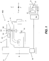
- FIG. 1 shows an embodiment of a CT imaging apparatus 400.
- a vertical column 3 supports a horizontal arm 2 that adjusts for the patient's height.
- Horizontal arm 2 supports a mount 4 on an axis 5.
- Mount 4 supports both an x-ray source 6 and, opposite the x-ray source, an x-ray sensor 7.
- Source 6 and sensor 7 are designed to rotate about axis 5, that is, with rotation in the x-y plane.
- the patient is positioned in line with axis 5 between the source 6 and the sensor 7, so that most of the radiation that is directed from source 6 toward sensor 7 passes through the patient.
- a patient positioning apparatus 14 that is coupled to CT imaging apparatus 400 and may include a chin support, a bite element, temporal holders, ear rods, a forehead support, or a strap for fixing the position of the patient's head, for example.
- a patient positioning apparatus 14 may include a chin support, a bite element, temporal holders, ear rods, a forehead support, or a strap for fixing the position of the patient's head, for example.
- the mount rotates to each of a number of different angular positions about axis 5, an image of the patient is obtained.
- apparatus 400 is calibrated so that axis 5 has a default position in the (x,y) plane corresponding to the vertical location of a given anatomical point of the patient, such as the incisors for example.
- a control logic processor 90 is in signal communication with a user interface, shown in FIG. 1 as a remote computer 50 with a display 51.
- the display screen shows a virtual model of a patient arch 52 and a target 53 having the shape of a cross, circle, cross-hairs, or other suitable shape.
- the user can displace and re-position target 53. This command is typically entered using a computer mouse or other type of pointer.
- Target 53 can then be positioned on a location of the virtual arch 52 that corresponds to the region of interest of the patient.
- the target location is sent to processor 90.
- Processor 90 then performs the needed computation and, as needed, actuates motors 31, 32 so that axis 5 is positioned at the vertical position of the region of interest of the patient corresponding to the virtual position of the target on virtual dental arch 52 shown on display 51.
- computer 50 and its related display 51 are integral with imaging apparatus 400, such as part of processor 90.
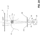
- FIG. 2A shows, from a schematic top view, parameters and features of the CT scan geometry that relate to the operation of CT imaging apparatus 400 of FIG. 1 .
- the axis of rotation 5 aligns with, or extends through, the center 11a of a region of interest 11.
- region of interest 11 is that portion of a dental arch 10 that is to be scanned.
- patient positioning apparatus 14 fixes the head of the patient into position for imaging and brings center 11a near axis of rotation 5; however, some additional adjustment is typically required in order to correct the positioning within the x-y plane.
- control logic processor 90 such as a microprocessor or other dedicated logic controller or computer device, is in signal communication with motors 31, 32, 33, and sensing devices and coordinates the operation of imaging apparatus 400 components during setup, axis alignment, and scanning.
- One or more sensor elements 44 in signal communication with control logic processor 90, sense the axial and rotational position of the rotatable mount.
- the patient is positioned at patient positioning apparatus 14, which places the head of the patient at a fixed position between source 6 and sensor 7. With the patient in position, the axis of rotation 5 is conveniently horizontally positioned, within the 2-dimensional (2D) x-y plane using motors 31 and 32. CT scanning can then be initiated.
- Motor 33 is energized and mount 4 rotates about fixed axis 5 to reach successive angular positions, denoted by angle ⁇ ( FIG. 2A ).
- Angle ⁇ indicates the angle between the line L1 and a front-to-rear direction 12 of the patient, termed the anteroposterior direction and shown in a dashed line in FIGS. 2A and 2B .
- focal spot 30 of the x-ray source 6 is located within a cavity defined by a container of lead or other suitable x-ray absorbing material, provided with an opening, aperture 6a.
- the beam 24 that passes through aperture 6a is then further limited by collimator 20.
- angle ⁇ is at 0 degrees.
- angle ⁇ is at some other angle that lies between 0 and 90 degrees.
- x-ray source 6 irradiates the region of interest 11 and a frame of image data is captured.
- a plurality of frames of the region of interest 11 of the patient are captured at various angular positions ⁇ of line L1 relative to the patient.
- the angular position ⁇ ranges from 0 to 180° for some CT embodiments or from 0-360° for other embodiments.
- control logic processor 90 From the plurality of two dimensional frames, control logic processor 90, or other computer that is in signal communication with processor 90 for receiving image data, reconstructs a 3D matrix of grey levels, corresponding to the absorption coefficients of elementary volume elements or voxels of the region of interest 11 that is being radiated.
- FIGS. 2A and 2B show two lines L1 and L2 at different angular positions of the scan.
- Line L1 passes through a focal spot 30 of the x-ray source and the vertical projection of the axis 5.
- Line L2 indicates the center of the x-ray beam as it is directed through aperture 6a and through an opening 23 provided by a collimator 20.
- lines L1 and L2 are collinear. This geometric relationship requires that center 11a be aligned with axis 5. This requirement, in turn, requires the use of motors 31 and 32, along with the necessary control logic sequence that is used for repositioning axis 5 in the x-y plane of FIG. 1 , depending on the region of interest.
- the x-y plane is the plane of the page for FIGS. 2A and 2B .
- the region of interest could include, for example, particular teeth of the patient, such as incisors, right or left molars, or other dental structures.
- the dentist needs information about only a small part of the dental arch, for example, for only two or three teeth.
- a CT scan with a small field of view is performed, the x-ray beam being tightly collimated by collimator 20 ( FIG. 2A ).
- This allows the electronic imaging sensor 7 to be reduced in size and lower in price and, because it requires only a small size x-ray beam, can help to reduce the overall amount of ionizing radiation to the patient.
- One drawback with conventional CT apparatus relates to the need for precise 2D positioning of the axis of rotation 5 relative to center 11a, even where only a small portion of the dental arch is to be imaged.
- motors 31 and 32 to position axis 5 adds cost and complexity to imaging apparatus 400 and adds weight to horizontal arm 2. In addition, extra setup time is needed for readying apparatus 400 in preparation to image each patient. Applicants desire to reduce or eliminate one or both of these motors to reduce cost, weight, and complexity of the apparatus and to improve workflow and efficiency in the use of the CT imaging equipment.
- Embodiments of the present application are described which reduce/eliminate precise positioning of the axis of rotation relative to the patient and to the center of the region of interest 11.
- axis of rotation 5 is positioned at the center 11a of the region of interest 11 relative to the x-y plane.
- collimator 20 is used to center the radiation beam toward region of interest 11 at each image acquisition angle, that is, with the mount rotated to each angular position, rather than requiring that the radiation beam be centered on axis of rotation 5.
- axis of rotation 5 lies outside the radiation beam that is emitted from the source and centered on the region of interest for at least one angular position of imaging source and sensor components over the range of scan angles.
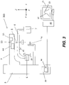
- FIG. 3 there is shown a CT imaging apparatus 300 that uses a collimator 20 for radiation beam centering.
- a number of components used in CT imaging apparatus 300 are similar to those used in CT imaging apparatus 400.
- motors 31 and 32 while required in the FIG. 1 embodiment, are not required for CT imaging apparatus 300 in FIG. 3 .
- Motor 31 is shown in FIG. 3 , but is optional.
- the axis of rotation (axis 5 in FIGS. 1 , 2A , 2B , and 3 ) is fixed with respect to imaging apparatus 300 and to the x-y plane.
- the patient is positioned at a predetermined location using positioning apparatus 14 that is located, relative to the mount 4, so that the vertical projection of axis 5 coincides with a point in the vicinity of the center of the mouth or of the dental arch or other feature of the patient.
- the center 11a of the region of interest 11 need not coincide with the vertical projection of axis of rotation 5 and may be spaced apart from axis 5, so that axis 5 lies outside the emitted radiation beam for the acquired image at one or more angular positions of mount 4.
- One or more sensor elements 44 in signal communication with control logic processor 90, sense the rotational position of rotatable mount 4 and, alternately, also sense the relative positions of axis of rotation 5 and positioning apparatus 14.
- Mount 4 can be vertically translated; arm 2 is movable in a vertical direction along vertical column 3.
- Control logic processor 90 executes control software 92 for performing mount 4 positioning functions, including rotation, vertical displacement, and positioning of axis of rotation 5. To perform any of these functions, control logic processor 90 accepts operator instructions and, optionally, obtains signals from one or more sensors that are part of CT imaging apparatus 300. Methods for sensing and providing movement in a dental imaging apparatus are known to those skilled in the dental apparatus design arts.
- Positioning axis of rotation 5 at a known position relative to the patient can be performed in a number of ways.
- apparatus 300 including patient support 14, is designed so that when the patient is positioned, axis of rotation 5 is in a known relationship with the patient, for example at the vertical position of an area of the patient's mouth.
- Apparatus 300 is provided with optional computer unit 50 including display 51 in communication with processor 90.
- Computer unit 50 can be a remote computer or processor or can be integral with apparatus 300.
- the user By positioning a target 53 on the virtual arch 52 using a computer mouse or other suitable pointer, the user defines region of interest 11 of the patient. This information is then sent to processor 90. Information about the location of region of interest 11 then provides a reference for precise actuation of collimator 20 to aim the radiation beam.
- Collimator 20 serves for beam centering at each angular position according to an embodiment of the present invention.
- FIG. 4A shows components that form and control collimator 20 according to an embodiment wherein the collimator provides a beam that has a rectangular shape in cross section.
- Collimator 20 is a blade collimator, provided with paired blades 21a, 21b that are appropriately positioned by motors 25. In conventional practice, the blades are positioned in such a manner that the center of opening 23 of the collimator is precisely positioned on the straight line L1. In the plan view of FIG. 4A , line L1 extends outwards, normal to the page.
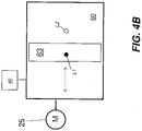
- FIG. 4B shows a collimator 60 in an alternate embodiment of the present invention.
- a slit 63 provides the collimator opening, which is not adjustable in size.
- Motor 25 is coupled to collimator 60 for horizontal movement, as shown.
- a single motor 25 is used for translating the plate provided with its opening slit, in place of paired blades 21a, 21b.
- Slit collimator 60 can be used in place of blade collimator 20 in embodiments shown subsequently.
- a single motor 25 can be used in a similar manner for translating a plate that is provided with slit 63 in place of the two blades 21b.
- Slit 63 can vary in dimensions, based on capabilities or constraints of the imaging system components.
- Other types of collimators are used in alternate embodiments of the present invention, such as those providing circular and elliptical apertures; these collimator types are similarly equipped to shift the central axis of the projected radiation beam away from the standard axis of line L1.
- the dentist needs information about only a small part of the dental arch, for example, from only two or three teeth.
- a CT scan with a small field of view is performed, the x-ray beam being tightly collimated by collimator 20.
- the solution provided in embodiments of the present invention is advantaged for a number of reasons.
- the electronic x-ray imaging sensor 7 can be reduced in size and lower in price.
- this limited field of view requires only a small size x-ray beam that is collimated by collimator 20, the amount of ionizing radiation that is directed to the patient is reduced.
- one drawback with conventional CT apparatus relates to the need for precise 2D positioning of the axis of rotation 5, aligning axis 5 with center 11a, even where only a small portion of the dental arch is to be imaged.
- Embodiments of the present invention relax this requirement, simplifying setup and use of the CT imaging apparatus, such as when only a limited-scan CT image is needed.
- FIGS. 2A and 2B showed how lines L1 and L2 are collinear for conventional CBCT imaging.
- Line L1 passes through focal spot 30 of the x-ray source 6 and through the vertical projection of the axis 5.
- Line L2 indicates the center of the x-ray beam as it is directed through opening 23 of collimator 20 and, in the conventional arrangement, passes through the vertical projection of axis 5.
- Embodiments of the present invention allow these lines to be non-collinear and non-parallel and, instead, use the collimator to control beam projection and centering at each imaging angle.
- angle ⁇ of the scan between the straight line L1 and the anteroposterior direction 12, motors 25 of collimator 20 FIG.
- the rotation axis 5 lies outside the centered radiation beam.
- the accumulation of frames in an angle ⁇ angular range from 0° to 180° or from 0° to 360° gives the information needed for the complete reconstruction of the 3D matrix of absorption coefficients.
- the position of collimator blades 21a is sensed and is used for image capture and for sensor 7 positioning, as described in more detail subsequently.
- motors 25 are stepping motors, allowing tracking information on blade positioning as part of actuation.
- one or more sensors 46 FIGS. 4A , 4B
- mount 4 is positioned at a predefined angle ⁇ position.
- optional motor 31 FIG. 3
- Motor 31 moves mount 4 to each angle ⁇ for imaging according to instructions entered by the operator, such as using computer unit 50 or using one or more controls 45 provided on the equipment for mount 4 positioning.
- motor 31 is responsive to operator movement and runs in an "assist" mode.
- motor 31 is actuated as needed to shift the position of mount 4 based on sensing the direction in which an operator is manually pushing against or pulling mount 4.
- an optional control 45 is used to actuate motor 31 to move mount 4 in a desired direction.
- region of interest 11 is also identified and stored by control software as prerequisite information or as part of an initial mount positioning step 100. Consistent with an embodiment of the present invention, region of interest 11 is defined in coordinate space, relative to the axis of rotation 5 as an origin or reference.
- region of interest 11 is entered by target positioning, as described previously with reference to FIG. 1 or manually by the operator, such as at computer unit 50 ( FIG. 3 ).
- region of interest 11 is specified by identifying the specific teeth or other structures to be imaged as well indicating the relative size of the patient, or providing other information related to relative patient dimensions, or using a standard setup procedure that is suited to a child or adult patient size. Appropriate positioning of the patient and use of a template corresponding to standard patient dimensions provides a suitable estimate of the appropriate location of region of interest 11.
- processor 90 uses the position information for region of interest 11 and the detected, existing position of imaging components on mount 4 and executes control software instructions that calculate the desired position of lateral blades 21a for the new angular position of mount 4.
- processor 90 uses the position information for region of interest 11 and the detected, existing position of imaging components on mount 4 and executes control software instructions that calculate the desired position of lateral blades 21a for the new angular position of mount 4.
- a collimator centering step 104 one or more of motors 25 of collimator 20 ( FIG. 4A ) are energized under control of the software executing on control logic processor 90 to position the collimator opening 23, such as positioning lateral blades 21a appropriately, so that the radiation beam through collimator 20 is centered about region of interest 11 with center 11a.
- FIGS. 5A through 5E show, the positioning of the opening 23 of collimator 20 is recalculated for each angular position ⁇ at which an image is obtained.
- This calculation takes into account the relative angular displacement of region of interest 11 from axis 5 and adjusts collimator 20 so that radiation is centered about line L2, which is displaced by angle ⁇ from line L1.
- slit 63 is correspondingly positioned so that radiation is centered about line L2.
- Other collimator embodiments perform similar centering of the collimator aperture.
- embodiments of the present invention help to reduce the overall amount of data needed for effective CT imaging of teeth and other structures.
- the imaged portion of sensor 7 can require less than 70% of the available pixels, such as less than 60%, less than 50%, or less than 40%, for example.
- the corresponding area of irradiated pixels can be varied according to the mount rotation angle ⁇ .
- the system calculates which pixels of sensor 7 are to be read at the given angular position.
- the x-ray source is energized and at an imaging step 110 selected pixels are read.
- the processor calculates a three dimensional matrix of x-ray absorption coefficients from the obtained image.
- a 3-dimensional (3D) matrix of a region of interest can then be obtained on the basis of a suitable number of image frames.
- Pixel selection relative to the given angular position of the mount and the collimator position and opening location can be performed in a number of ways and can vary with rotation angle.
- lines L1 and L2 are directed from focal spot 30 at a corresponding angle ⁇ , based on the relative distance of region of the center 11a of the region of interest 11 from axis of rotation 5 at that mount angle. Because the distance between focal spot 30 and x-ray sensor 7 is constant and line L1 through focal spot 30 and axis 5 is normal to the collimator 20 and to the surface of sensor 7, the center position at which line L2 intersects the sensor 7 relative to line L1 is proportional to sin ⁇ . Further, the position of collimator 20 from the focal spot 30 is also fixed.
- the width of the radiation beam, centered at line L2 can be computed in a straightforward manner, once the size of the collimator aperture, that is, the relative location of collimator edges away from line L1 is known.
- the corresponding edges of the imaged area on x-ray sensor 7 are then simply computed using straightforward geometric relationships.
- CMOS or TFT sensor technology allows selection of pixels to be read by well known pixel addressing techniques.
- pixels can be selected to change the size of the image according to the size of region of interest 11.
- this selection of pixels is used essentially to selectively read the pixels corresponding to the area of the sensor that the collimated x-ray beam impinges upon.
- the extra-oral dental imaging device allows the 3D matrix of absorption coefficients of any region of interest of the patient's mouth to be obtained without the need for precisely positioning axis 5 so that it extends through center 11a during the imaging sequence, thus making it unnecessary to require motors 31 and 32 as in the FIG. 1 embodiment.
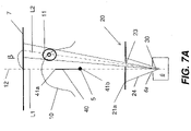
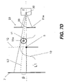
- FIGS. 7A through 7D An alternate embodiment of the present invention is shown in the sequence of FIGS. 7A through 7D .
- axis 5 can be displaced along one direction.
- a single motor 31 is mounted in horizontal arm 2 as was shown in FIG. 1 .
- Motor 31 is energizable to provide translational movement of axis 5 along a single direction, preferably in the anteroposterior direction 12.
- axis 5 can then be positioned in any location between two extreme positions 41a and 41b of a segment 40 that corresponds to the extent of movement provided by motor 31.
- the position of axis 5 on segment 40 is chosen in such a way that the area of the sensor 7 that is subtended by angle ⁇ is reduced to obtain only useful image data for the region of interest 11 or is, more generally, chosen to have a position that simplifies acquisition of the corresponding image, such as by positioning axis 5 or source 6 as close as possible to center 11a of region of interest 11, for example.
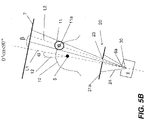
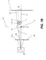
- FIGS. 8A through 8D Another alternate embodiment of the present invention, offering the capability for improved resolution over embodiments described previously, is shown in the sequence of FIGS. 8A through 8D .
- axis 5 can be displaced along one direction.
- angle ⁇ between the line L1 and the anteroposterior direction 12 that is, for each angular position, the position of axis 5 on segment 40 is chosen in such a way that source 6 is as close as possible to region of interest 11.
- the projection of the x-rayed object on sensor 7 is as large as possible, helping to increase image resolution.
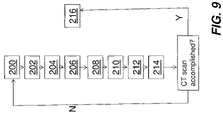
- a positioning step 200 mount 4 is positioned at a predefined angle ⁇ position about the axis.
- the processor calculates the most convenient position of axis 5 along segment 40, as described with reference to FIG. 7A .
- a calculation step 204 motor 31 positions the axis in the calculated position.
- the processor calculates the position of lateral blades 21a for the new angular position of mount 4.
- a collimator positioning step 208 motors 25 of collimator 20 position lateral blades 21a.
- the processor calculates which pixels of sensor 7 are to be read at the given angular position.
- the x-ray source is energized and the image obtained in an image acquisition step 214, with selected pixels read.
- the processor calculates a three dimensional matrix of x-ray absorption coefficients in a calculation step 216.
- patient support, positioning apparatus 14 of apparatus 300 is designed so that segment 40 coincides with the plane of symmetry of the patient and so that one extremity position 41b of the segment is in a known relationship relative to the anatomy of the patient and is, for example at the vertical position, or height position, of the patient's mouth.
- the same arrangement of computer unit 50 components and manipulation of target 53 position to define the location of axis 5, described previously with respect to FIG. 3 also apply for the alternate embodiments shown in FIGS. 7A-7D and 8A-8D .
- the region of interest can include a region of one single dental arch, either maxillae or mandible, or the opposite region of both dental arches, depending on the position of the collimator blades 21a or 21b defining the vertical width of collimator 20 ( FIG. 4A ).
- Control logic processor 90 can be a dedicated microprocessor or host computer associated with the CT imaging apparatus, or on some other computer processing system, including a remotely networked processor, for example. It can be appreciated that functions such as control of the rotational position of the imaging hardware, image acquisition, image data processing, and generation and display of volume image data can be performed from a single computer system or using a group or network of computers and host processors that interact with each other to control system components and to provide these functions.
- control logic processor 90 ( FIG. 3 ) stores and executes control software that generates, for one or more rotation positions of the rotatable mount, a signal for collimator adjustment for centering the beam on the region of interest.
- FIGS. 5A-5E , 7A - 7D , and 8A - 8D show displacement of the center of the emitted radiation along a horizontal direction, that is, relative to the plane of the page as viewed in these figures. It is to be observed that some amount of vertical displacement, out of the plane of the page, can alternately be provided in addition where collimator 20 allows vertical beam adjustment, as shown in the example of FIG. 4A . Horizontal blades 21b can be positioned suitably for this purpose, so that the x-ray beam is directed from an angle, with corresponding image data obtained at a vertical position on x-ray sensor 7.
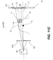
- the schematic diagram of FIG. 10 shows the use of collimator 20 in diverting the X-ray beam along line L2 in the vertical (z) direction.
- calculation step 206 optionally includes the added calculations for vertical adjustment of the opening of collimator 20 for this purpose.
- Vertical blades 21b are then moved as part of positioning step 208. It should be noted that the capability to adjust the angle of the emitted beam with respect to vertical gives a measure of added control to the standard height adjustment that is provided for arm 2 and mount 4.
- control logic processor 90 controls which pixels provide image data at a particular rotation angle ⁇ and compensate for this slight difference in angular spread.
- the digital x-ray sensor that is used for CT imaging is a costly component.
- only a portion of the x-ray detector is needed for obtaining image data at each angular position ⁇ . This means that a considerable amount of the imageable area is wasted when obtaining the series of 2-D images used for CT image reconstruction.
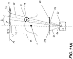
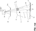
- FIGS. 11A-11D there is shown an embodiment of the present invention that addresses the cost problem by employing a smaller sensor 70 that is moved along a track 72.
- One or more motors 74 and 76 are provided to urge sensor 70 along track 72 for obtaining the image at each rotation angle ⁇ .
- Control logic processor 90 coordinates positioning of sensor 70 along track 72 according to the mount angle ⁇ and the detected coordinates for opening 23 of collimator 20.
- a single motor is actuable to urge sensor 70 to each position along track 72.
- gears or belts can be used for moving the sensor 70.
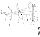
- a stepping motor 80 actuates a worm screw device 82 (a so-called endless screw) that urges sensor 70 along track 72.
- a worm screw device 82 a so-called endless screw
- the use of a stepping motor allows a precise determination and control of the actual position of sensor 70 along the track.
- Two motion sensors 84, 88 are positioned at both extremities of track 72 to determine the precise reference points for the start and the end of the length of stroke of sensor 70.
- These motion sensors 84, 88 can send a signal to processor 90 to stop the displacement of sensor 70 when it reaches an end of the stroke.
- the position of sensor 70 can also be determined using a resistive track 72: the measured electric resistance from track 72 is proportional to or is a function of the distance between a point of sensor 70 and a reference point on the sliding track.
- a computer or other logic processor executes a program with stored instructions that control aspects of apparatus operation for obtaining an image and, optionally, also process image data accessed from the x-ray sensor or stored in an electronic memory.
- a computer program of an embodiment of the present invention can be utilized by a suitable, general-purpose computer system, such as a personal computer or workstation, as well as by a microprocessor or other dedicated processor or programmable logic device.
- a suitable, general-purpose computer system such as a personal computer or workstation
- a microprocessor or other dedicated processor or programmable logic device such as a microprocessor or other dedicated processor or programmable logic device.
- many other types of computer systems can be used to execute the computer program of the present invention, including networked processors.
- the computer program for performing the method of the present invention may be stored in a computer readable storage medium.
- This medium may comprise, for example; magnetic storage media such as a magnetic disk (such as a hard drive) or magnetic tape or other portable type of magnetic disk; optical storage media such as an optical disc, optical tape, or machine readable bar code; solid state electronic storage devices such as random access memory (RAM), or read only memory (ROM); or any other physical device or medium employed to store a computer program.
- the computer program for performing the method of the present invention may also be stored on computer readable storage medium that is connected to the image processor by way of the internet or other communication medium. Those skilled in the art will readily recognize that the equivalent of such a computer program product may also be constructed in hardware.
- the computer program product of the present invention may make use of various image manipulation algorithms and processes that are well known. It will be further understood that the computer program product embodiment of the present invention may embody algorithms and processes not specifically shown or described herein that are useful for implementation. Such algorithms and processes may include conventional utilities that are within the ordinary skill of the image processing arts. Additional aspects of such algorithms and systems, and hardware and/or software for producing and otherwise obtaining and processing the images or co-operating with the computer program product of the present invention, are not specifically shown or described herein and may be selected from such algorithms, systems, hardware, components and elements known in the art.
- memory can refer to any type of temporary or more enduring data storage workspace used for storing and operating upon image data and accessible to a computer system.
- the memory could be non-volatile, using, for example, a long-term storage medium such as magnetic or optical storage. Alternately, the memory could be of a more volatile nature, using an electronic circuit, such as random-access memory (RAM) that is used as a temporary buffer or workspace by a microprocessor or other control logic processor device.
- Display data for example, is typically stored in a temporary storage buffer that is directly associated with a display device and is periodically refreshed as needed in order to provide displayed data.
- This temporary storage buffer can also be considered to be a memory, as the term is used in the present disclosure.
- Memory is also used as the data workspace for executing and storing intermediate and final results of calculations and other processing.
- Computer-accessible memory can be volatile, non-volatile, or a hybrid combination of volatile and non-volatile types. Computer-accessible memory of various types is provided on different components throughout the system for storing, processing, transferring, and displaying data, and for other functions.
- the terms "operator”, and “user” are considered to be equivalent and refer to the technician or practitioner or other person who sets up and initializes a partial CT imaging scan.
Description
- The present invention relates generally to the field of volumetric imaging and more particularly to apparatus and methods for obtaining volumetric images of teeth and other structures within the head.
- A computerized tomography (CT) or cone beam CT (CBCT) imaging apparatus operates by acquiring multiple 2D images with a rotating imaging ensemble or gantry that has an x-ray source and, opposite the x-ray source, an imaging sensor rotating about a fixed axis relative to the patient who is being imaged. CT and CBCT imaging allow the reconstruction of 3D or volume images of anatomical structures of the patient. The resulting volume images are acknowledged to be of particular value for obtaining useful information for assisting diagnosis and treatment. In the context of the present disclosure, the term "CT" is used to include CT systems of various types, including CBCT systems.
- There is interest in the use of CT imaging in dental and ear-nose- throat (ENT) applications, as well as for other imaging of the patient's head.
- Reference is also made
US 2004 / 202 283 A1 disclosing an X-ray CT apparatus including at least one X-ray irradiation source, at least one X-ray detector, at least one collimator configured to create an opening that is movable in at least one of a slice direction and a channel direction, at least one image processing part configured to extract a portion of the volume data, a controller configured to set the opening of the at least one collimator to a second opening size according to a cylinder-like second scanning range that is set to limit the volume of interest and configured to perform a second scan, and at least one reconstruction part. -
EP 2 364 648 A1 -
US 2003 / 076 920 A1 discloses an X-ray computed tomography apparatus including a first and a second data detecting system. A reconstructing unit reconstructs image data on the basis of the data detected by at least one of the first and second data detecting systems. A monitoring unit monitors the first data detecting system. In a period during which the first data detecting system is normal, data acquisition is performed by both the first and second data detecting systems. In a period during which the first data detecting system is faulty, data acquisition is performed by the second data detecting system alone. -
US 6 501 828 B1 discloses a method and an apparatus for influencing x-rays in a beam path, the x-ray apparatus having an x-ray source and an x-ray receiver, the x-ray source being adjustable relative to a subject and emitting x-rays in the direction toward the x-ray receiver during the course of radiological exposures of the subject. The x-ray apparatus has an arrangement in the beam path of the x-rays for influencing the shape and/or the intensity profile of the x-ray beam, and this arrangement is dynamically adjustable during radiological exposures of the subject for influencing the shape and/or the intensity profile of the x-rays. - In accordance with the present invention, an apparatus for computed tomography imaging as set forth in claim 1 and a method for computed tomography imaging as set forth in claim 9 is provided.
- Further embodiments of the invention are inter alia disclosed in the dependent claims. Embodiments of the present invention address the need for advancing the CT imaging art, particularly for imaging of teeth and other structures of the head. Embodiments of the present invention provide an apparatus for CT imaging that dynamically adjusts the radiation beam, centering the beam apart from the axis of rotation using the collimator assembly, so that, relative to an x-y plane, precision placement of an axis so that it extends through a center of the region of interest is not necessary.
- These objects are given only by way of illustrative example, and such objects may be exemplary of one or more embodiments of the invention. Other desirable objectives and advantages inherently achieved by the disclosed invention may occur or become apparent to those skilled in the art. The invention is defined by the appended claims.
- The foregoing and other objects, features, and advantages of the invention will be apparent from the following more particular description of the embodiments of the invention, as illustrated in the accompanying drawings. The elements of the drawings are not necessarily to scale relative to each other. Some exaggeration of feature sizes or their geometrical or angular relationships may be useful to show features of the present invention with improved clarity.
-
FIG. 1 is a schematic diagram that shows an extra-oral CT dental imaging apparatus. -
FIG. 2A is a top view that shows angular relationships for CT imaging at a first angle. -
FIG. 2B is a top view that shows angular relationships for CT imaging at a second angle, displaced from the first angle ofFIG. 2A . -
FIG. 3 is a schematic diagram that shows an extra-oral CT dental imaging apparatus according to an embodiment of the present invention. -
FIG. 4A is a schematic diagram that shows components of a blade collimator for CT imaging. -
FIG. 4B is a schematic diagram that shows a slit collimator for CT imaging. -
FIGS. 5A-5E show top views illustrating different angles in an imaging sequence using the adjustable collimator for beam direction according to an embodiment of the present invention. -
FIG. 6 is a logic flow diagram that lists the steps for obtaining a CT scan according to an embodiment of the present invention. -
FIGS. 7 A - 7D are top views that show different angles in an imaging sequence using the adjustable collimator for beam direction according to an alternate embodiment of the present invention. -
FIGS. 8A - 8D are top views that show different angles in an imaging sequence using the adjustable collimator for beam direction according to another alternate embodiment of the present invention. -
FIG. 9 is a logic flow diagram that lists the steps for obtaining a CT scan according to an alternate embodiment of the present invention. -
FIG. 10 is a schematic diagram that shows the use of a blade collimator for diverting the X-ray beam in the vertical direction. -
FIGS. 11 A - 11 D are top views that show different angles in an imaging sequence using the adjustable collimator for beam direction along with a smaller sensor that is moved along a track according to an embodiment of the present invention. -
FIG. 11 E is a schematic diagram showing an alternate embodiment for movement of the x-ray sensor along a track. - The following is a detailed description of the preferred embodiments of the invention, reference being made to the drawings in which the same reference numerals identify the same elements of structure in each of the several figures.
- In the context of the present invention, the terms "digital sensor" and "digital detector" are considered to be equivalent. These describe the panel that obtains image data in a digital radiography system. The term "revolve" has its conventional meaning, to move in a curved path or orbit around a center point.
- Where they are used, the terms "first", "second", "third", and so on, do not necessarily denote any ordinal or priority relation, but may be used for more clearly distinguishing one element or time interval from another.
- As used herein, the term "energizable" relates to a device or set of components that can be energized to perform an indicated function upon receiving power and, optionally, upon receiving an enabling signal. The term "actuable" has its conventional meaning, relating to a device or component that is capable of effecting an action in response to a stimulus, such as in response to an electrical signal, for example.
- Consistent with the present disclosure, lines are substantially in parallel when their directions differ by no more than about 0.5 degree. At angles exceeding this range, lines are considered to be non-parallel.
-
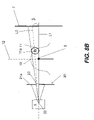
FIG. 1 shows an embodiment of aCT imaging apparatus 400. Avertical column 3 supports ahorizontal arm 2 that adjusts for the patient's height.Horizontal arm 2 supports amount 4 on anaxis 5. Mount 4 supports both anx-ray source 6 and, opposite the x-ray source, anx-ray sensor 7.Source 6 andsensor 7 are designed to rotate aboutaxis 5, that is, with rotation in the x-y plane. The patient is positioned in line withaxis 5 between thesource 6 and thesensor 7, so that most of the radiation that is directed fromsource 6 towardsensor 7 passes through the patient. The fixed positioning of the patient is made possible by apatient positioning apparatus 14 that is coupled toCT imaging apparatus 400 and may include a chin support, a bite element, temporal holders, ear rods, a forehead support, or a strap for fixing the position of the patient's head, for example. As the mount rotates to each of a number of different angular positions aboutaxis 5, an image of the patient is obtained. - At installation,
apparatus 400 is calibrated so thataxis 5 has a default position in the (x,y) plane corresponding to the vertical location of a given anatomical point of the patient, such as the incisors for example. Acontrol logic processor 90 is in signal communication with a user interface, shown inFIG. 1 as aremote computer 50 with adisplay 51. The display screen shows a virtual model of apatient arch 52 and atarget 53 having the shape of a cross, circle, cross-hairs, or other suitable shape. Using a command that indicates a point of the virtual model of thepatient arch 52, the user can displace and re-positiontarget 53. This command is typically entered using a computer mouse or other type of pointer.Target 53 can then be positioned on a location of thevirtual arch 52 that corresponds to the region of interest of the patient. Once the new position of the target is validated by the user, the target location is sent toprocessor 90.Processor 90 then performs the needed computation and, as needed, actuatesmotors axis 5 is positioned at the vertical position of the region of interest of the patient corresponding to the virtual position of the target on virtual dental arch 52 shown ondisplay 51. Alternately,computer 50 and itsrelated display 51 are integral withimaging apparatus 400, such as part ofprocessor 90. -
FIG. 2A shows, from a schematic top view, parameters and features of the CT scan geometry that relate to the operation ofCT imaging apparatus 400 ofFIG. 1 . For conventional CT scanning, the axis ofrotation 5 aligns with, or extends through, thecenter 11a of a region ofinterest 11. For dental imaging, region ofinterest 11 is that portion of adental arch 10 that is to be scanned. The use ofpatient positioning apparatus 14 fixes the head of the patient into position for imaging and bringscenter 11a near axis ofrotation 5; however, some additional adjustment is typically required in order to correct the positioning within the x-y plane. - Referring again to
FIG. 1 , adjustment or horizontal displacement ofaxis 5 position is performed using X andY motors horizontal arm 2. Before the beginning of a scan, the axis ofrotation 5 is positioned relative to the patient at the vertical position of thecenter 11a of the region ofinterest 11 of the patient. Amotor 33 inhorizontal arm 2 is energized to provide rotation ofmount 4 aboutaxis 5.Control logic processor 90, such as a microprocessor or other dedicated logic controller or computer device, is in signal communication withmotors imaging apparatus 400 components during setup, axis alignment, and scanning. One ormore sensor elements 44, in signal communication withcontrol logic processor 90, sense the axial and rotational position of the rotatable mount. - As shown in
FIG. 1 , the patient is positioned atpatient positioning apparatus 14, which places the head of the patient at a fixed position betweensource 6 andsensor 7. With the patient in position, the axis ofrotation 5 is conveniently horizontally positioned, within the 2-dimensional (2D) x-yplane using motors Motor 33 is energized andmount 4 rotates about fixedaxis 5 to reach successive angular positions, denoted by angle α (FIG. 2A ). Angle α indicates the angle between the line L1 and a front-to-rear direction 12 of the patient, termed the anteroposterior direction and shown in a dashed line inFIGS. 2A and2B . - In
FIGS. 2A and2B ,focal spot 30 of thex-ray source 6 is located within a cavity defined by a container of lead or other suitable x-ray absorbing material, provided with an opening,aperture 6a. Thebeam 24 that passes throughaperture 6a is then further limited bycollimator 20. - In
FIG. 2A , angle α is at 0 degrees. InFIG. 2B , angle α is at some other angle that lies between 0 and 90 degrees. At each of a number of angular positions,x-ray source 6 irradiates the region ofinterest 11 and a frame of image data is captured. Continuing in this manner, a plurality of frames of the region ofinterest 11 of the patient are captured at various angular positions α of line L1 relative to the patient. The angular position α ranges from 0 to 180° for some CT embodiments or from 0-360° for other embodiments. From the plurality of two dimensional frames,control logic processor 90, or other computer that is in signal communication withprocessor 90 for receiving image data, reconstructs a 3D matrix of grey levels, corresponding to the absorption coefficients of elementary volume elements or voxels of the region ofinterest 11 that is being radiated. - The schematic views of
FIGS. 2A and2B show two lines L1 and L2 at different angular positions of the scan. Line L1 passes through afocal spot 30 of the x-ray source and the vertical projection of theaxis 5. Line L2 indicates the center of the x-ray beam as it is directed throughaperture 6a and through anopening 23 provided by acollimator 20. In conventional CT systems, lines L1 and L2 are collinear. This geometric relationship requires thatcenter 11a be aligned withaxis 5. This requirement, in turn, requires the use ofmotors axis 5 in the x-y plane ofFIG. 1 , depending on the region of interest. The x-y plane is the plane of the page forFIGS. 2A and2B . The region of interest could include, for example, particular teeth of the patient, such as incisors, right or left molars, or other dental structures. - In some cases, the dentist needs information about only a small part of the dental arch, for example, for only two or three teeth. In that case, a CT scan with a small field of view is performed, the x-ray beam being tightly collimated by collimator 20 (
FIG. 2A ). This allows theelectronic imaging sensor 7 to be reduced in size and lower in price and, because it requires only a small size x-ray beam, can help to reduce the overall amount of ionizing radiation to the patient. One drawback with conventional CT apparatus, however, relates to the need for precise 2D positioning of the axis ofrotation 5 relative tocenter 11a, even where only a small portion of the dental arch is to be imaged. - The use of
motors axis 5 adds cost and complexity toimaging apparatus 400 and adds weight tohorizontal arm 2. In addition, extra setup time is needed for readyingapparatus 400 in preparation to image each patient. Applicants desire to reduce or eliminate one or both of these motors to reduce cost, weight, and complexity of the apparatus and to improve workflow and efficiency in the use of the CT imaging equipment. - Embodiments of the present application are described which reduce/eliminate precise positioning of the axis of rotation relative to the patient and to the center of the region of
interest 11. As was shown with respect toFIGS. 1 and2A , axis ofrotation 5 is positioned at thecenter 11a of the region ofinterest 11 relative to the x-y plane. Using embodiments of the present application for a CBCT scan, the configuration can differ. Instead,collimator 20 is used to center the radiation beam toward region ofinterest 11 at each image acquisition angle, that is, with the mount rotated to each angular position, rather than requiring that the radiation beam be centered on axis ofrotation 5. According to an embodiment of the present application, axis ofrotation 5 lies outside the radiation beam that is emitted from the source and centered on the region of interest for at least one angular position of imaging source and sensor components over the range of scan angles. - Referring to
FIG. 3 , there is shown aCT imaging apparatus 300 that uses acollimator 20 for radiation beam centering. By comparison withFIG. 1 , a number of components used inCT imaging apparatus 300 are similar to those used inCT imaging apparatus 400. Notably,motors FIG. 1 embodiment, are not required forCT imaging apparatus 300 inFIG. 3 .Motor 31 is shown inFIG. 3 , but is optional. The axis of rotation (axis 5 inFIGS. 1 ,2A ,2B , and3 ) is fixed with respect toimaging apparatus 300 and to the x-y plane. The patient is positioned at a predetermined location using positioningapparatus 14 that is located, relative to themount 4, so that the vertical projection ofaxis 5 coincides with a point in the vicinity of the center of the mouth or of the dental arch or other feature of the patient. In general, thecenter 11a of the region ofinterest 11 need not coincide with the vertical projection of axis ofrotation 5 and may be spaced apart fromaxis 5, so thataxis 5 lies outside the emitted radiation beam for the acquired image at one or more angular positions ofmount 4. One ormore sensor elements 44, in signal communication withcontrol logic processor 90, sense the rotational position ofrotatable mount 4 and, alternately, also sense the relative positions of axis ofrotation 5 andpositioning apparatus 14.Mount 4 can be vertically translated;arm 2 is movable in a vertical direction alongvertical column 3.Control logic processor 90 executescontrol software 92 for performingmount 4 positioning functions, including rotation, vertical displacement, and positioning of axis ofrotation 5. To perform any of these functions,control logic processor 90 accepts operator instructions and, optionally, obtains signals from one or more sensors that are part ofCT imaging apparatus 300. Methods for sensing and providing movement in a dental imaging apparatus are known to those skilled in the dental apparatus design arts. - Positioning axis of
rotation 5 at a known position relative to the patient can be performed in a number of ways. According to an embodiment of the present invention,apparatus 300, includingpatient support 14, is designed so that when the patient is positioned, axis ofrotation 5 is in a known relationship with the patient, for example at the vertical position of an area of the patient's mouth.Apparatus 300 is provided withoptional computer unit 50 includingdisplay 51 in communication withprocessor 90.Computer unit 50 can be a remote computer or processor or can be integral withapparatus 300. By positioning atarget 53 on thevirtual arch 52 using a computer mouse or other suitable pointer, the user defines region ofinterest 11 of the patient. This information is then sent toprocessor 90. Information about the location of region ofinterest 11 then provides a reference for precise actuation ofcollimator 20 to aim the radiation beam. -
Collimator 20 serves for beam centering at each angular position according to an embodiment of the present invention.FIG. 4A shows components that form andcontrol collimator 20 according to an embodiment wherein the collimator provides a beam that has a rectangular shape in cross section.Collimator 20 is a blade collimator, provided with pairedblades motors 25. In conventional practice, the blades are positioned in such a manner that the center of opening 23 of the collimator is precisely positioned on the straight line L1. In the plan view ofFIG. 4A , line L1 extends outwards, normal to the page. -
FIG. 4B shows acollimator 60 in an alternate embodiment of the present invention. Aslit 63 provides the collimator opening, which is not adjustable in size.Motor 25 is coupled tocollimator 60 for horizontal movement, as shown. According to the embodiment of the presentinvention using collimator 60, asingle motor 25 is used for translating the plate provided with its opening slit, in place of pairedblades Slit collimator 60 can be used in place ofblade collimator 20 in embodiments shown subsequently. Asingle motor 25 can be used in a similar manner for translating a plate that is provided withslit 63 in place of the twoblades 21b.Slit 63 can vary in dimensions, based on capabilities or constraints of the imaging system components. Other types of collimators are used in alternate embodiments of the present invention, such as those providing circular and elliptical apertures; these collimator types are similarly equipped to shift the central axis of the projected radiation beam away from the standard axis of line L1. - In some cases, the dentist needs information about only a small part of the dental arch, for example, from only two or three teeth. In such a case, a CT scan with a small field of view is performed, the x-ray beam being tightly collimated by
collimator 20. The solution provided in embodiments of the present invention is advantaged for a number of reasons. First, the electronicx-ray imaging sensor 7 can be reduced in size and lower in price. Secondly, since this limited field of view requires only a small size x-ray beam that is collimated bycollimator 20, the amount of ionizing radiation that is directed to the patient is reduced. - As noted earlier, one drawback with conventional CT apparatus relates to the need for precise 2D positioning of the axis of
rotation 5, aligningaxis 5 withcenter 11a, even where only a small portion of the dental arch is to be imaged. Embodiments of the present invention relax this requirement, simplifying setup and use of the CT imaging apparatus, such as when only a limited-scan CT image is needed. -
FIGS. 2A and2B showed how lines L1 and L2 are collinear for conventional CBCT imaging. Line L1 passes throughfocal spot 30 of thex-ray source 6 and through the vertical projection of theaxis 5. Line L2 indicates the center of the x-ray beam as it is directed through opening 23 ofcollimator 20 and, in the conventional arrangement, passes through the vertical projection ofaxis 5. Embodiments of the present invention allow these lines to be non-collinear and non-parallel and, instead, use the collimator to control beam projection and centering at each imaging angle. At each angular position, angle α of the scan between the straight line L1 and theanteroposterior direction 12,motors 25 of collimator 20 (FIG. 4A ) are energized to position thelateral blades 21a in such a way that center line L2 of the x-ray beam generated byfocal spot 30 and passing throughcollimator 20 passes throughcenter 11a of the region of interest, which need not coincide with the projection ofaxis 5. This behavior is shown at different angles in the sequence ofFIGS. 5A-5E . In each case, the center of opening 23 ofcollimator 20 is not positioned on the straight line L1. Consequently, both straight lines L1 and L2 may not trace the same path as they do in conventional practice; instead, lines L1 and L2 are respectively non-parallel, at a non-zero angle β. At each image acquisition angle α in theFIGS. 5A-5E sequence, therotation axis 5 lies outside the centered radiation beam. The accumulation of frames in an angle α angular range from 0° to 180° or from 0° to 360° gives the information needed for the complete reconstruction of the 3D matrix of absorption coefficients. The position ofcollimator blades 21a is sensed and is used for image capture and forsensor 7 positioning, as described in more detail subsequently. According to an embodiment of the present invention,motors 25 are stepping motors, allowing tracking information on blade positioning as part of actuation. Alternately, one or more sensors 46 (FIGS. 4A ,4B ) provide the needed information on where one or both edges of the collimator aperture lie. - The complete scan is then performed following a succession of steps for an identified
center 11a of region ofinterest 11, as outlined in the logic flow diagram ofFIG. 6 . At amount positioning step 100,mount 4 is positioned at a predefined angle α position. As part of initialmount positioning step 100, optional motor 31 (FIG. 3 ) can be used to repositionmount 4 and thus axis ofrotation 5 to a suitable angular position, as indicated by the technician or other operator.Motor 31 moves mount 4 to each angle α for imaging according to instructions entered by the operator, such as usingcomputer unit 50 or using one ormore controls 45 provided on the equipment formount 4 positioning. According to an alternate embodiment of the present invention,motor 31 is responsive to operator movement and runs in an "assist" mode. In this mode,motor 31 is actuated as needed to shift the position ofmount 4 based on sensing the direction in which an operator is manually pushing against or pullingmount 4. According to another alternate embodiment, anoptional control 45 is used to actuatemotor 31 to movemount 4 in a desired direction. - The position of region of
interest 11 is also identified and stored by control software as prerequisite information or as part of an initialmount positioning step 100. Consistent with an embodiment of the present invention, region ofinterest 11 is defined in coordinate space, relative to the axis ofrotation 5 as an origin or reference. - The coordinates of region of
interest 11 are entered by target positioning, as described previously with reference toFIG. 1 or manually by the operator, such as at computer unit 50 (FIG. 3 ). According to an alternate embodiment, region ofinterest 11 is specified by identifying the specific teeth or other structures to be imaged as well indicating the relative size of the patient, or providing other information related to relative patient dimensions, or using a standard setup procedure that is suited to a child or adult patient size. Appropriate positioning of the patient and use of a template corresponding to standard patient dimensions provides a suitable estimate of the appropriate location of region ofinterest 11. - At a
calculation step 102,processor 90 uses the position information for region ofinterest 11 and the detected, existing position of imaging components onmount 4 and executes control software instructions that calculate the desired position oflateral blades 21a for the new angular position ofmount 4. At acollimator centering step 104, one or more ofmotors 25 of collimator 20 (FIG. 4A ) are energized under control of the software executing oncontrol logic processor 90 to position thecollimator opening 23, such aspositioning lateral blades 21a appropriately, so that the radiation beam throughcollimator 20 is centered about region ofinterest 11 withcenter 11a. AsFIGS. 5A through 5E show, the positioning of theopening 23 ofcollimator 20 is recalculated for each angular position α at which an image is obtained. This calculation takes into account the relative angular displacement of region ofinterest 11 fromaxis 5 and adjustscollimator 20 so that radiation is centered about line L2, which is displaced by angle β from line L1. In embodiments that use theslit collimator 60 that is shown inFIG. 4B , slit 63 is correspondingly positioned so that radiation is centered about line L2. Other collimator embodiments perform similar centering of the collimator aperture. - Using a blade arrangement as shown in
FIG. 4A , it is possible to adjust the boundaries of the radiation beam so that only a portion of thex-ray sensor 7 receives image content. Using the slit arrangement ofFIG. 4B , boundaries of the slit are fixed; similarly, only a portion of thesensor 7 receives image content with the slit collimator configuration. As is shown in the sequence ofFIGS. 5A through 5E , the portion of thesensor 7 that obtains the image data varies with either blade or slit collimators, depending on rotation angle α. The partial imaged area ofsensor 7 can vary from one angular setting to the hext. Using the basic sequence described herein, it is straightforward to determine which pixels ofsensor 7 are affected at each angular position. By reading only irradiated pixels and ignoring the larger body of repetitive pixel values that have no diagnostic utility, embodiments of the present invention help to reduce the overall amount of data needed for effective CT imaging of teeth and other structures. For example, the imaged portion ofsensor 7 can require less than 70% of the available pixels, such as less than 60%, less than 50%, or less than 40%, for example. It should also be noted that for embodiments in which the size of the collimator opening is adjustable, the corresponding area of irradiated pixels can be varied according to the mount rotation angle α. - At an
optional calculation step 106, the system calculates which pixels ofsensor 7 are to be read at the given angular position. At anexposure step 108, the x-ray source is energized and at animaging step 110 selected pixels are read. Once the CT scan is completed, at astep 112, the processor calculates a three dimensional matrix of x-ray absorption coefficients from the obtained image. A 3-dimensional (3D) matrix of a region of interest can then be obtained on the basis of a suitable number of image frames. - Pixel selection relative to the given angular position of the mount and the collimator position and opening location can be performed in a number of ways and can vary with rotation angle. At each angular position of
mount 4, lines L1 and L2 are directed fromfocal spot 30 at a corresponding angle β, based on the relative distance of region of thecenter 11a of the region ofinterest 11 from axis ofrotation 5 at that mount angle. Because the distance betweenfocal spot 30 andx-ray sensor 7 is constant and line L1 throughfocal spot 30 andaxis 5 is normal to thecollimator 20 and to the surface ofsensor 7, the center position at which line L2 intersects thesensor 7 relative to line L1 is proportional to sin β. Further, the position ofcollimator 20 from thefocal spot 30 is also fixed. Thus, the width of the radiation beam, centered at line L2, can be computed in a straightforward manner, once the size of the collimator aperture, that is, the relative location of collimator edges away from line L1 is known. The corresponding edges of the imaged area onx-ray sensor 7 are then simply computed using straightforward geometric relationships. - Providing
sensor 70 using CMOS or TFT sensor technology allows selection of pixels to be read by well known pixel addressing techniques. In conventional imaging apparatus, pixels can be selected to change the size of the image according to the size of region ofinterest 11. According to an embodiment of the present invention, this selection of pixels is used essentially to selectively read the pixels corresponding to the area of the sensor that the collimated x-ray beam impinges upon. - Advantageously, the extra-oral dental imaging device according to embodiments of the present invention allows the 3D matrix of absorption coefficients of any region of interest of the patient's mouth to be obtained without the need for precisely positioning
axis 5 so that it extends throughcenter 11a during the imaging sequence, thus making it unnecessary to requiremotors FIG. 1 embodiment. - An alternate embodiment of the present invention is shown in the sequence of
FIGS. 7A through 7D . Here,axis 5 can be displaced along one direction. Asingle motor 31 is mounted inhorizontal arm 2 as was shown inFIG. 1 .Motor 31 is energizable to provide translational movement ofaxis 5 along a single direction, preferably in theanteroposterior direction 12. As shown inFIG. 7A ,axis 5 can then be positioned in any location between twoextreme positions segment 40 that corresponds to the extent of movement provided bymotor 31. For each value of angle α between the line L1 and theanteroposterior direction 12, that is, for each angular position that is used for imaging, the position ofaxis 5 onsegment 40 is chosen in such a way that the area of thesensor 7 that is subtended by angle β is reduced to obtain only useful image data for the region ofinterest 11 or is, more generally, chosen to have a position that simplifies acquisition of the corresponding image, such as by positioningaxis 5 orsource 6 as close as possible to center 11a of region ofinterest 11, for example. - Another alternate embodiment of the present invention, offering the capability for improved resolution over embodiments described previously, is shown in the sequence of
FIGS. 8A through 8D . Here,axis 5 can be displaced along one direction. For each value of angle α between the line L1 and theanteroposterior direction 12, that is, for each angular position, the position ofaxis 5 onsegment 40 is chosen in such a way that source 6 is as close as possible to region ofinterest 11. With this relationship, the projection of the x-rayed object onsensor 7 is as large as possible, helping to increase image resolution. - The complete scan for the alternate embodiments of
Figures 7A-7D and8A-8D is then performed following the succession of steps given inFIG. 9 . In apositioning step 200,mount 4 is positioned at a predefined angle α position about the axis. In acalculation step 202, the processor calculates the most convenient position ofaxis 5 alongsegment 40, as described with reference toFIG. 7A . In anaxis positioning step 204,motor 31 positions the axis in the calculated position. In acalculation step 206, the processor calculates the position oflateral blades 21a for the new angular position ofmount 4. In acollimator positioning step 208,motors 25 ofcollimator 20position lateral blades 21a. In anoptional calculation step 210, the processor calculates which pixels ofsensor 7 are to be read at the given angular position. In anexposure step 212, the x-ray source is energized and the image obtained in animage acquisition step 214, with selected pixels read. At completion of the CT scanning to obtain each image at a different angular position using these steps, the processor calculates a three dimensional matrix of x-ray absorption coefficients in acalculation step 216. - In the embodiment described with reference to
FIGS. 7A-7D , patient support,positioning apparatus 14 ofapparatus 300 is designed so thatsegment 40 coincides with the plane of symmetry of the patient and so that oneextremity position 41b of the segment is in a known relationship relative to the anatomy of the patient and is, for example at the vertical position, or height position, of the patient's mouth. The same arrangement ofcomputer unit 50 components and manipulation oftarget 53 position to define the location ofaxis 5, described previously with respect toFIG. 3 , also apply for the alternate embodiments shown inFIGS. 7A-7D and8A-8D . - In the embodiments described, the region of interest can include a region of one single dental arch, either maxillae or mandible, or the opposite region of both dental arches, depending on the position of the
collimator blades FIG. 4A ). - Processing for generating the extra-oral imaging data to provide a volume image can be executed on
control logic processor 90, which can be a dedicated microprocessor or host computer associated with the CT imaging apparatus, or on some other computer processing system, including a remotely networked processor, for example. It can be appreciated that functions such as control of the rotational position of the imaging hardware, image acquisition, image data processing, and generation and display of volume image data can be performed from a single computer system or using a group or network of computers and host processors that interact with each other to control system components and to provide these functions. - Among its functions for control and image acquisition, control logic processor 90 (
FIG. 3 ) stores and executes control software that generates, for one or more rotation positions of the rotatable mount, a signal for collimator adjustment for centering the beam on the region of interest. -
FIGS. 5A-5E ,7A - 7D , and8A - 8D show displacement of the center of the emitted radiation along a horizontal direction, that is, relative to the plane of the page as viewed in these figures. It is to be observed that some amount of vertical displacement, out of the plane of the page, can alternately be provided in addition wherecollimator 20 allows vertical beam adjustment, as shown in the example ofFIG. 4A .Horizontal blades 21b can be positioned suitably for this purpose, so that the x-ray beam is directed from an angle, with corresponding image data obtained at a vertical position onx-ray sensor 7. The schematic diagram ofFIG. 10 shows the use ofcollimator 20 in diverting the X-ray beam along line L2 in the vertical (z) direction. Referring toFIG. 9 ,calculation step 206 optionally includes the added calculations for vertical adjustment of the opening ofcollimator 20 for this purpose.Vertical blades 21b are then moved as part ofpositioning step 208. It should be noted that the capability to adjust the angle of the emitted beam with respect to vertical gives a measure of added control to the standard height adjustment that is provided forarm 2 andmount 4. - It should be noted that in the various embodiments of the CT imaging apparatus shown herein, wherein lines L1 and L2 follow separate paths, the x-ray radiation can be incident on
sensor 7 at slightly larger angles than with conventional imaging wherein lines L1 and L2 follow the same path, as described previously with reference toFIGS. 2A and2B . According to an alternate embodiment of the present invention, image processing algorithms performed bycontrol logic processor 90, bycomputer 50, or by some other computer determine which pixels provide image data at a particular rotation angle α and compensate for this slight difference in angular spread. - The digital x-ray sensor that is used for CT imaging is a costly component. The larger the sensor, the higher the cost. As noted with reference to embodiments in
FIGS. 5A-5D and following, only a portion of the x-ray detector is needed for obtaining image data at each angular position α. This means that a considerable amount of the imageable area is wasted when obtaining the series of 2-D images used for CT image reconstruction. Referring toFIGS. 11A-11D , there is shown an embodiment of the present invention that addresses the cost problem by employing asmaller sensor 70 that is moved along atrack 72. One ormore motors sensor 70 alongtrack 72 for obtaining the image at each rotation angle α. - For moving
sensor 70 to the various angular positions in theFIG. 11A-11D sequence, the same considerations and calculations described previously for reading only the imaged pixels apply. Instead of using only a small portion of the image area of the sensor, embodiments of the present invention allow more efficient use of the sensor, translating the sensor to a suitable position for each imaging angle.Control logic processor 90 coordinates positioning ofsensor 70 alongtrack 72 according to the mount angle α and the detected coordinates for opening 23 ofcollimator 20. According to an alternate embodiment of the present invention, a single motor is actuable to urgesensor 70 to each position alongtrack 72. Various arrangements of gears or belts can be used for moving thesensor 70. - Techniques for providing sliding movement of an x-ray sensor on a panel are well-known in the art of standard linear tomography. In conventional devices, both the sensor and the source translate in parallel, moving either in the same direction or in opposite directions. According to an alternate embodiment of the present invention as shown in
Figure 11E , a steppingmotor 80 actuates a worm screw device 82 (a so-called endless screw) that urgessensor 70 alongtrack 72. The use of a stepping motor allows a precise determination and control of the actual position ofsensor 70 along the track. Twomotion sensors track 72 to determine the precise reference points for the start and the end of the length of stroke ofsensor 70. Thesemotion sensors processor 90 to stop the displacement ofsensor 70 when it reaches an end of the stroke. Alternately, the position ofsensor 70 can also be determined using a resistive track 72: the measured electric resistance fromtrack 72 is proportional to or is a function of the distance between a point ofsensor 70 and a reference point on the sliding track. - Consistent with an embodiment of the present invention, a computer or other logic processor executes a program with stored instructions that control aspects of apparatus operation for obtaining an image and, optionally, also process image data accessed from the x-ray sensor or stored in an electronic memory. As can be appreciated by those skilled in the image processing arts, a computer program of an embodiment of the present invention can be utilized by a suitable, general-purpose computer system, such as a personal computer or workstation, as well as by a microprocessor or other dedicated processor or programmable logic device. However, many other types of computer systems can be used to execute the computer program of the present invention, including networked processors. The computer program for performing the method of the present invention may be stored in a computer readable storage medium. This medium may comprise, for example; magnetic storage media such as a magnetic disk (such as a hard drive) or magnetic tape or other portable type of magnetic disk; optical storage media such as an optical disc, optical tape, or machine readable bar code; solid state electronic storage devices such as random access memory (RAM), or read only memory (ROM); or any other physical device or medium employed to store a computer program. The computer program for performing the method of the present invention may also be stored on computer readable storage medium that is connected to the image processor by way of the internet or other communication medium. Those skilled in the art will readily recognize that the equivalent of such a computer program product may also be constructed in hardware.
- It will be understood that the computer program product of the present invention may make use of various image manipulation algorithms and processes that are well known. It will be further understood that the computer program product embodiment of the present invention may embody algorithms and processes not specifically shown or described herein that are useful for implementation. Such algorithms and processes may include conventional utilities that are within the ordinary skill of the image processing arts. Additional aspects of such algorithms and systems, and hardware and/or software for producing and otherwise obtaining and processing the images or co-operating with the computer program product of the present invention, are not specifically shown or described herein and may be selected from such algorithms, systems, hardware, components and elements known in the art.
- It should be noted that the term "memory", equivalent to "computer-accessible memory" in the context of the present disclosure, can refer to any type of temporary or more enduring data storage workspace used for storing and operating upon image data and accessible to a computer system. The memory could be non-volatile, using, for example, a long-term storage medium such as magnetic or optical storage. Alternately, the memory could be of a more volatile nature, using an electronic circuit, such as random-access memory (RAM) that is used as a temporary buffer or workspace by a microprocessor or other control logic processor device. Display data, for example, is typically stored in a temporary storage buffer that is directly associated with a display device and is periodically refreshed as needed in order to provide displayed data. This temporary storage buffer can also be considered to be a memory, as the term is used in the present disclosure. Memory is also used as the data workspace for executing and storing intermediate and final results of calculations and other processing. Computer-accessible memory can be volatile, non-volatile, or a hybrid combination of volatile and non-volatile types. Computer-accessible memory of various types is provided on different components throughout the system for storing, processing, transferring, and displaying data, and for other functions.
- In the context of the present disclosure, the terms "operator", and "user" are considered to be equivalent and refer to the technician or practitioner or other person who sets up and initializes a partial CT imaging scan.
- The invention has been described in detail with particular reference to a presently preferred embodiment, but it will be understood that variations and modifications can be effected within the scope of the invention. The presently disclosed embodiments are therefore considered in all respects to be illustrative and not restrictive. The scope of the invention is indicated by the appended claims.
Claims (12)
- An apparatus for computed tomography imaging (400; 300) of a region of interest (11) within the head of a patient, comprising:a rotatable mount (4) that is actuable to rotate about a vertical rotation axis (5) and that is configured to support, at opposite ends, an x-ray source (6) and a detector (7; 70) configured for obtaining a plurality of frame images, wherein the x-ray source (6) is disposed to direct a radiation beam through the region of interest (11) and toward the detector (7; 70);a control logic processor (90) configured to control rotation of the rotatable mount (4) and to obtain image data at a first angular position and at least a second angular position about the rotation axis (5);a patient positioning apparatus (14) configured to position the patient's head in a known relationship relative to the rotation axis (5) during a computed tomography imaging process, wherein the region of interest (11) has a center (11a) that is spaced apart from the rotation axis (5); anda collimator (20; 60) disposed in front of the x-ray source (6) and controlled by the control logic processor (90) to center the radiation beam toward the center (11a) of the region of interest (11) at the first angular position and to adjust centering of the radiation beam toward the center (11a) of the region of interest (11) at the second angular position.
- The apparatus (400; 300) of claim 1, wherein the rotatable mount (4) comprises a motor (31, 32, 33) that is energizable to displace the position of the rotation axis (5) along one direction relative to the rotatable mount (4).
- The apparatus (400; 300) of claim 1, wherein the rotation axis (5) is supported by a horizontal arm (2), and wherein the horizontal arm (2) is movable along a vertical column (3), wherein the position of the rotation axis (5) is fixed along the horizontal arm (2).
- The apparatus (400; 300) of claim 2, wherein the direction corresponds to the anteroposterior direction relative to the patient, wherein the position of the rotation axis (5) further depends on the angular position of the mount (4).
- The apparatus (400; 300) of claim 1, further comprising one or more sensor elements (44) configured to sense the angular position of the rotatable mount (4),wherein the patient positioning apparatus (14) further comprises one or more of a chin support, a forehead support, a strap for fixing the position of the patient's head, an ear rod, a temporal holder, and a bite element,wherein the collimator (20; 60) is either a blade collimator (20) or a slit collimator (60).
- The apparatus (400; 300) of claim 1, wherein, for at least one of the first angular position and the at least a second angular position, the rotation axis (5) lies outside the centered radiation beam.
- The apparatus (400; 300) of claim 1, further comprising control software executable on the control logic processor (90) to generate, for one or more rotation positions of the rotatable mount (4), a signal for collimator (20; 60) adjustment for centering the beam on the region of interest (11).
- The apparatus (400; 300) of anyone of the preceding claims, wherein the detector (70) is positioned along a track (72) to a plurality of positions along the track (72) to form the image data according to the incident radiation beam.
- A method for computed tomography imaging of a patient, comprising:providing a rotatable mount that is actuable to rotate about a vertical rotation axis and that supports, at opposite ends, an x-ray source having a collimator and an x- ray detector for obtaining a plurality of frame images,wherein the x-ray source is disposed to direct a radiation beam through the patient and toward the detector; andwherein the patient's head is positioned in a known relationship relative to the rotation axis;accessing a region of interest within the head of the patient, the region of interest having a center that is spaced apart from the rotation axis;positioning (100; 200) the mount at a first angular position;calculating (101; 202) the position of a center of an opening of the collimator at the first angular position for centering a radiation beam about the center of the region of interest;acquiring (214) image data at the first angular position;rotating the mount to a second angular position;changing the position of the center of the opening of the collimator at the second angular position for centering a radiation beam about the center of the region of interest;acquiring (214) image data at the second angular position;forming (112; 212) a volume image according to at least image data acquired at the first and second angular positions; anddisplaying, transmitting, or storing the volume image.
- The method of claim 9, wherein identifying the region of interest (11) comprises adjusting a target on a display screen.
- The method of claim 9, wherein, for at least one of the plurality of angular positions, the rotation axis lies outside the centered radiation beam.
- The method of claim 9, further comprising:changing the position of the collimator opening relative to a vertical direction, andstoring one or more coordinates that identify the region of interest having a center that is spaced apart from the rotation axis.
Applications Claiming Priority (3)
| Application Number | Priority Date | Filing Date | Title |
|---|---|---|---|
| US201261698061P | 2012-09-07 | 2012-09-07 | |
| US201261736025P | 2012-12-12 | 2012-12-12 | |
| PCT/IB2013/000952 WO2014037770A1 (en) | 2012-09-07 | 2013-03-15 | Apparatus for partial ct imaging |
Publications (2)
| Publication Number | Publication Date |
|---|---|
| EP2892432A1 EP2892432A1 (en) | 2015-07-15 |
| EP2892432B1 true EP2892432B1 (en) | 2022-12-28 |
Family
ID=48700626
Family Applications (1)
| Application Number | Title | Priority Date | Filing Date |
|---|---|---|---|
| EP13732221.0A Active EP2892432B1 (en) | 2012-09-07 | 2013-03-15 | Apparatus for partial ct imaging |
Country Status (6)
| Country | Link |
|---|---|
| US (1) | US11154260B2 (en) |
| EP (1) | EP2892432B1 (en) |
| JP (1) | JP6370297B2 (en) |
| KR (1) | KR102124669B1 (en) |
| ES (1) | ES2935893T3 (en) |
| WO (1) | WO2014037770A1 (en) |
Families Citing this family (16)
| Publication number | Priority date | Publication date | Assignee | Title |
|---|---|---|---|---|
| JP5805688B2 (en) * | 2013-03-07 | 2015-11-04 | 株式会社モリタ製作所 | Medical X-ray equipment |
| DE102013215043A1 (en) * | 2013-07-31 | 2015-02-05 | Siemens Aktiengesellschaft | Method for imaging by means of an X-ray device and X-ray device |
| EP3146526B1 (en) * | 2014-05-19 | 2018-12-26 | 3Shape A/S | A radiographic system and method for reducing motion blur and scatter radiation |
| JP6448790B2 (en) * | 2014-12-04 | 2019-01-09 | トロフィー | Collimator for extraoral dental imaging device for head measurement |
| KR101661055B1 (en) * | 2015-01-08 | 2016-09-29 | 오스템임플란트 주식회사 | Apparatus and method for x-ray photographing |
| CN105982686B (en) * | 2015-01-30 | 2019-04-30 | 合肥美亚光电技术股份有限公司 | Computer tomography equipment and the method that faultage image is shot by it |
| JP6811716B2 (en) | 2015-02-27 | 2021-01-13 | トロフィー | Dental Imaging Equipment and Methods for Positioning Subjects for Dental Radiation Transmission Imaging |
| US10463330B2 (en) * | 2016-04-20 | 2019-11-05 | Swissray International, Inc. | Positioning and evaluation for mandible of patient |
| KR101928397B1 (en) | 2017-03-03 | 2018-12-12 | 오스템임플란트 주식회사 | Apparatus for calculating user alignment value and method for the same |
| EP3461417B1 (en) * | 2017-09-29 | 2020-07-22 | Trophy | A method and system for obtaining operating parameters for 3d x ray acquisition |
| US10948428B2 (en) | 2018-05-25 | 2021-03-16 | Delavan Inc. | Reducing scatter for computed tomography |
| WO2020067322A1 (en) * | 2018-09-27 | 2020-04-02 | 富士フイルム株式会社 | Radiographic device |
| KR102203548B1 (en) * | 2018-11-23 | 2021-01-15 | 오스템임플란트 주식회사 | Dental CT apparatus, Arranging method of dental CT apparatus and computer-readable recording medium |
| CN112912006A (en) * | 2019-09-24 | 2021-06-04 | 博医来股份公司 | Method and system for determining medical imaging system configuration |
| CN111388881B (en) * | 2020-03-23 | 2022-01-28 | 上海联影医疗科技股份有限公司 | Control method and system of beam limiting device |
| CN113069141B (en) * | 2021-03-31 | 2023-03-31 | 有方(合肥)医疗科技有限公司 | Method and system for shooting oral panoramic film, electronic equipment and readable storage medium |
Citations (5)
| Publication number | Priority date | Publication date | Assignee | Title |
|---|---|---|---|---|
| US20080187095A1 (en) * | 2005-05-03 | 2008-08-07 | The Regents Of The University Of California | Biopsy Systems For Breast Computed Tomography |
| DE102007014134A1 (en) * | 2007-03-23 | 2008-09-25 | Siemens Ag | Method for producing tomographic series radiogram of radiation sensitive investigation object, involves scanning of investigation object, which is to be examined is done with radiation beam with small fan angle |
| US20100091937A1 (en) * | 2008-09-30 | 2010-04-15 | Rainer Raupach | X-ray beam modifying diaphragm and diaphragm device |
| US20120063565A1 (en) * | 2010-09-15 | 2012-03-15 | Klaus Klingenbeck | Method for collimating to an off-center examination sub-object |
| US20120128120A1 (en) * | 2010-11-22 | 2012-05-24 | Bruno Kristiann Bernard De Man | System and method for breast imaging using x-ray computed tomography |
Family Cites Families (120)
| Publication number | Priority date | Publication date | Assignee | Title |
|---|---|---|---|---|
| US4817119A (en) * | 1977-08-25 | 1989-03-28 | National Biomedical Research Foundation | Method and apparatus for computerized tomographic scanning with plural intersecting sets of parallel radiation beams |
| US5090037A (en) * | 1990-11-19 | 1992-02-18 | General Electric Company | Helical scanning computed tomography with tracking x-ray source |
| US5224136A (en) * | 1992-06-30 | 1993-06-29 | General Electric Company | Helical scanning computed tomography apparatus with constrained tracking of the x-ray source |
| WO1995021515A1 (en) * | 1994-02-03 | 1995-08-10 | Analogic Corporation | X-ray tomography system for and method of improving the quality of a scanned image |
| US5550886A (en) * | 1994-11-22 | 1996-08-27 | Analogic Corporation | X-Ray focal spot movement compensation system |
| JP3331284B2 (en) | 1995-11-06 | 2002-10-07 | 株式会社モリタ製作所 | Medical X-ray tomography system |
| JP3807833B2 (en) * | 1996-12-10 | 2006-08-09 | 株式会社モリタ製作所 | X-ray equipment |
| JP3869083B2 (en) * | 1996-12-10 | 2007-01-17 | 株式会社モリタ製作所 | X-ray equipment |
| JP3919048B2 (en) * | 1998-09-02 | 2007-05-23 | 株式会社モリタ製作所 | Local irradiation X-ray CT imaging system |
| US6493415B1 (en) * | 1999-03-25 | 2002-12-10 | Nihon University | X-ray computed tomography method and apparatus |
| US6851851B2 (en) * | 1999-10-06 | 2005-02-08 | Hologic, Inc. | Digital flat panel x-ray receptor positioning in diagnostic radiology |
| US6282264B1 (en) * | 1999-10-06 | 2001-08-28 | Hologic, Inc. | Digital flat panel x-ray detector positioning in diagnostic radiology |
| DE19950794A1 (en) * | 1999-10-21 | 2001-06-13 | Siemens Ag | Radiological device e.g. for radiological imaging for computer tomography |
| DE10008053A1 (en) * | 2000-02-22 | 2001-09-06 | Siemens Ag | X-ray device and medical workplace for diagnostics and for surgical interventions in the head and jaw area of a patient |
| US6463122B1 (en) * | 2000-08-21 | 2002-10-08 | Bio-Imaging Resource, Inc. | Mammography of computer tomography for imaging and therapy |
| DE10196737T1 (en) * | 2000-10-04 | 2003-09-04 | Nihon University Tokio Tokyo | Display method and device for an x-ray projection image for medical purposes, x-ray CT device for medical purposes and storage medium for storing a program for executing the display method |
| JP3926120B2 (en) * | 2001-02-16 | 2007-06-06 | 株式会社モリタ製作所 | X-ray imaging position setting means for an object, and X-ray imaging apparatus provided with this means |
| JP3847101B2 (en) * | 2001-05-22 | 2006-11-15 | ジーイー・メディカル・システムズ・グローバル・テクノロジー・カンパニー・エルエルシー | X-ray CT apparatus and method |
| US7085343B2 (en) * | 2001-10-18 | 2006-08-01 | Kabushiki Kaisha Toshiba | X-ray computed tomography apparatus |
| JP4088058B2 (en) * | 2001-10-18 | 2008-05-21 | 株式会社東芝 | X-ray computed tomography system |
| ATE376389T1 (en) * | 2002-02-15 | 2007-11-15 | Breakaway Imaging Llc | GANTRY RING WITH REMOVABLE SEGMENT FOR MULTI-DIMENSIONAL X-RAY IMAGING |
| JP2005519688A (en) * | 2002-03-13 | 2005-07-07 | ブレークアウェイ・イメージング・エルエルシー | Pseudo simultaneous multiplanar X-ray imaging system and method |
| AU2003224711A1 (en) * | 2002-03-19 | 2003-10-08 | Breakaway Imaging, Llc | Computer tomograph with a detector following the movement of a pivotable x-ray source |
| FI128745B (en) * | 2002-04-11 | 2020-11-30 | J Morita Mfg Corp | X-ray ct tomographic equipment |
| JP3785576B2 (en) * | 2002-04-24 | 2006-06-14 | 株式会社モリタ製作所 | Subject blur correction means and medical X-ray imaging apparatus using the same |
| US7001045B2 (en) * | 2002-06-11 | 2006-02-21 | Breakaway Imaging, Llc | Cantilevered gantry apparatus for x-ray imaging |
| AU2003261200A1 (en) * | 2002-07-25 | 2004-02-25 | Dentsply International Inc. | Real-time digital x-ray imaging apparatus and method |
| JP2004180715A (en) * | 2002-11-29 | 2004-07-02 | Toshiba Corp | X-ray computed tomography apparatus |
| DE10313110A1 (en) * | 2003-03-24 | 2004-10-21 | Sirona Dental Systems Gmbh | X-ray device and X-ray sensitive camera |
| DE10313109A1 (en) * | 2003-03-24 | 2004-10-21 | Sirona Dental Systems Gmbh | X-ray sensitive camera and X-ray device |
| JP4163991B2 (en) * | 2003-04-30 | 2008-10-08 | 株式会社モリタ製作所 | X-ray CT imaging apparatus and imaging method |
| JP2005087592A (en) * | 2003-09-19 | 2005-04-07 | Hitachi Ltd | X-rays measuring instrument |
| DE102004028124B4 (en) * | 2004-06-09 | 2008-08-07 | Siemens Ag | Multi-mode imaging tomography device and method for changing the operating mode of the tomographic device |
| DE102004041440A1 (en) * | 2004-08-27 | 2006-03-02 | Dürr Dental GmbH & Co. KG | Method for determining the desired relative position of a patient in a dental panoramic X-ray device or the target path on which this is moved with respect to a patient and a device suitable for this purpose |
| JP2006061501A (en) * | 2004-08-27 | 2006-03-09 | Morita Mfg Co Ltd | X-ray equipment |
| CN2796650Y (en) * | 2005-03-31 | 2006-07-19 | 西门子(中国)有限公司 | Computer tomography system capable of regulating distance of focus to detector |
| JP4488948B2 (en) * | 2005-04-11 | 2010-06-23 | 株式会社モリタ製作所 | X-ray CT imaging unit and X-ray imaging apparatus |
| DE112006000869B4 (en) * | 2005-04-11 | 2017-10-19 | J. Morita Mfg. Corp. | Radiography device with overview image function |
| FI118413B (en) * | 2005-04-11 | 2007-11-15 | Planmeca Oy | Computed tomography system |
| JP4307406B2 (en) * | 2005-04-22 | 2009-08-05 | 株式会社モリタ製作所 | Medical X-ray imaging apparatus and X-ray detector used therefor |
| US7336763B2 (en) * | 2005-05-02 | 2008-02-26 | Oy Ajat Ltd | Dental extra-oral x-ray imaging system and method |
| US7742560B2 (en) * | 2005-05-02 | 2010-06-22 | Oy Ajat Ltd. | Radiation imaging device with irregular rectangular shape and extraoral dental imaging system therefrom |
| JP4632891B2 (en) * | 2005-07-22 | 2011-02-16 | 株式会社モリタ製作所 | X-ray CT imaging apparatus and X-ray CT imaging method |
| JP4567064B2 (en) * | 2005-10-17 | 2010-10-20 | 株式会社モリタ製作所 | Medical digital X-ray equipment |
| US8433033B2 (en) * | 2005-10-21 | 2013-04-30 | Axion Japan Co., Ltd. | Panoramic imaging apparatus |
| JP2007135658A (en) | 2005-11-15 | 2007-06-07 | Ge Medical Systems Global Technology Co Llc | X-ray ct apparatus and x-ray ct fluoroscopic apparatus |
| DK1815794T3 (en) * | 2006-02-01 | 2016-02-01 | Dental Imaging Technologies Corp | Dental X-ray device and method for positioning a patient therein |
| CN101505658B (en) | 2006-08-17 | 2015-08-19 | 皇家飞利浦电子股份有限公司 | computed tomography image acquisition |
| US8488736B2 (en) * | 2006-09-19 | 2013-07-16 | General Electric Company | Stacked flat panel x-ray detector assembly and method of making same |
| US8483352B2 (en) * | 2006-09-19 | 2013-07-09 | General Electric Company | Stacked x-ray detector assembly and method of making same |
| US8483353B2 (en) * | 2006-09-19 | 2013-07-09 | General Electric Company | Integrated X-ray detector assembly and method of making same |
| WO2008035828A1 (en) * | 2006-09-22 | 2008-03-27 | Ray Co., Ltd. | Dental complex imaging system |
| US7486759B2 (en) * | 2006-10-12 | 2009-02-03 | J. Morita Manufacturing Corporation | X-ray computer tomography apparatus |
| KR100861409B1 (en) * | 2006-12-13 | 2008-10-08 | 주식회사바텍 | Panoramic x-ray photographing apparatus and method for photographing using the same |
| DK2119326T3 (en) * | 2007-01-24 | 2017-05-22 | Dental Imaging Tech Corp | Adjustable scanner |
| JP2008229322A (en) * | 2007-02-22 | 2008-10-02 | Morita Mfg Co Ltd | Image processing method, image displaying method, image processing program, storage medium, image processor, and x-ray imaging device |
| US7787586B2 (en) * | 2007-02-22 | 2010-08-31 | J. Morita Manufacturing Corporation | Display method of X-ray CT image of maxillofacial area, X-ray CT apparatus and X-ray image display apparatus |
| US9597041B2 (en) * | 2007-03-30 | 2017-03-21 | General Electric Company | Sequential image acquisition with updating method and system |
| JP4739278B2 (en) * | 2007-05-11 | 2011-08-03 | 株式会社モリタ製作所 | X-ray CT imaging system |
| JP2009005984A (en) * | 2007-06-28 | 2009-01-15 | Morita Mfg Co Ltd | X-ray ct photography apparatus |
| EP2210559B1 (en) * | 2007-11-16 | 2016-09-07 | J. Morita Manufacturing Corporation | X-ray ct imaging device |
| FR2924325B1 (en) * | 2007-12-03 | 2010-11-26 | Trophy | DENTAL RADIOLOGY APPARATUS AND ASSOCIATED METHOD. |
| CN101470086B (en) * | 2007-12-29 | 2012-11-28 | 清华大学 | Detector apparatus and CT checking system with the same |
| US8009794B2 (en) * | 2008-01-30 | 2011-08-30 | Varian Medical Systems, Inc. | Methods, apparatus, and computer-program products for increasing accuracy in cone-beam computed tomography |
| CN101965153B (en) * | 2008-02-20 | 2014-08-06 | 图像科学国际有限公司 | Adjustable scanner |
| WO2009128063A1 (en) * | 2008-04-14 | 2009-10-22 | Arineta Ltd. | Ct cone beam scanner |
| JP5368817B2 (en) * | 2008-04-24 | 2013-12-18 | 浜松ホトニクス株式会社 | Medical X-ray imaging system |
| JP5058057B2 (en) * | 2008-04-24 | 2012-10-24 | 浜松ホトニクス株式会社 | Medical X-ray imaging system |
| JP5390512B2 (en) * | 2008-04-30 | 2014-01-15 | 株式会社モリタ製作所 | Medical X-ray CT system |
| US8538110B2 (en) * | 2008-05-01 | 2013-09-17 | J. Morita Manufacturing Corporation | Medical X-ray CT imaging apparatus, medical X-ray CT image display device, and medical X-ray CT image display method |
| DE102008035412A1 (en) * | 2008-07-29 | 2010-02-04 | Sirona Dental Systems Gmbh | Method for producing a dental 3D X-ray image and X-ray device therefor |
| FR2938183B1 (en) * | 2008-08-22 | 2011-12-09 | Trophy | PANORAMIC DENTAL RADIOLOGY APPARATUS AND METHOD OF USE THEREOF |
| FR2938182B1 (en) * | 2008-08-22 | 2010-11-19 | Trophy | DENTAL RADIOLOGY APPARATUS AND METHOD OF USE THEREOF |
| JP5569951B2 (en) * | 2008-09-01 | 2014-08-13 | 学校法人日本大学 | X-ray CT imaging apparatus for head and imaging control method thereof |
| US8525833B2 (en) * | 2008-10-13 | 2013-09-03 | George Papaioannou | Dynamic biplane roentgen stereophotogrammetric analysis |
| CN101897593B (en) * | 2009-05-26 | 2014-08-13 | 清华大学 | Computer chromatography imaging device and method |
| BRPI1009661A2 (en) * | 2009-06-18 | 2016-03-15 | Koninkl Philips Electronics Nv | method and system |
| WO2010150719A1 (en) * | 2009-06-25 | 2010-12-29 | 株式会社吉田製作所 | X-ray photographing device |
| JP2011019633A (en) * | 2009-07-14 | 2011-02-03 | Toshiba Corp | X-ray diagnostic apparatus and control program for reducing exposure dose |
| JP5731386B2 (en) * | 2009-07-30 | 2015-06-10 | 株式会社テレシステムズ | Radiation imaging apparatus and imaging method using radiation |
| US9084568B2 (en) * | 2009-08-05 | 2015-07-21 | Telesystems Co., Ltd. | Radiation imaging apparatus and imaging method using radiation |
| JP5529461B2 (en) * | 2009-08-19 | 2014-06-25 | 株式会社モリタ製作所 | Medical X-ray equipment |
| US8588364B2 (en) * | 2009-08-19 | 2013-11-19 | J. Morita Manufacturing Corporation | Medical X-ray apparatus |
| JP4516626B1 (en) * | 2009-09-28 | 2010-08-04 | 株式会社吉田製作所 | Dental X-ray equipment |
| CN102576387B (en) * | 2009-10-22 | 2016-08-03 | 皇家飞利浦电子股份有限公司 | Sweep parameter strategy |
| US8451972B2 (en) * | 2009-10-23 | 2013-05-28 | Arineta Ltd. | Methods, circuits, devices, apparatus, assemblies and systems for computer tomography |
| US8515007B2 (en) * | 2009-12-15 | 2013-08-20 | Midmark Corporation | Motion system for panoramic dental radiation imaging system |
| JP5479069B2 (en) * | 2009-12-17 | 2014-04-23 | 株式会社東芝 | X-ray CT apparatus and control method of X-ray CT apparatus |
| JP5744573B2 (en) * | 2010-03-12 | 2015-07-08 | 株式会社モリタ製作所 | X-ray equipment |
| KR101523422B1 (en) * | 2010-05-11 | 2015-05-27 | 텔레시스템즈 가부시키가이샤 | Radiation imaging apparatus and phantom used for the same |
| US8430565B2 (en) * | 2010-06-02 | 2013-04-30 | Palodex Group Oy | X-ray device having head stabilizing member |
| WO2011156526A2 (en) * | 2010-06-08 | 2011-12-15 | Accuray, Inc. | Imaging methods and target tracking for image-guided radiation treatment |
| WO2012008492A1 (en) * | 2010-07-13 | 2012-01-19 | 株式会社テレシステムズ | X-ray tomogram imaging device |
| JP5395958B2 (en) * | 2010-08-09 | 2014-01-22 | 株式会社吉田製作所 | X-ray equipment |
| JP5757660B2 (en) * | 2010-08-11 | 2015-07-29 | 学校法人日本大学 | X-ray equipment |
| JP5663245B2 (en) | 2010-09-07 | 2015-02-04 | 株式会社日立メディコ | X-ray CT system |
| US8768029B2 (en) * | 2010-10-20 | 2014-07-01 | Medtronic Navigation, Inc. | Selected image acquisition technique to optimize patient model construction |
| US8184775B1 (en) * | 2010-10-29 | 2012-05-22 | General Electric Company | Dynamic collimator for wide coverage and low dose cardiac CT imaging |
| CN103415253B (en) * | 2010-12-09 | 2015-11-25 | 皇家飞利浦电子股份有限公司 | For the Post-patient dynamic filter of computer tomography (CT) |
| US9389320B2 (en) | 2010-12-21 | 2016-07-12 | Takara Telesystems Corp. | Radiation detector, and radiation imaging apparatus provided with detector |
| US9636076B2 (en) * | 2011-03-29 | 2017-05-02 | Toshiba Medical Systems Corporation | X-ray CT apparatus and image processing method |
| RU2014105575A (en) * | 2011-07-15 | 2015-08-27 | Конинклейке Филипс Н.В. | DYNAMIC COLLIMATION |
| JP5711200B2 (en) * | 2011-11-02 | 2015-04-30 | 株式会社モリタ製作所 | Panoramic X-ray tomography apparatus and image processing apparatus |
| JP5864403B2 (en) * | 2011-11-30 | 2016-02-17 | 株式会社モリタ製作所 | X-ray CT imaging system |
| JP5746990B2 (en) * | 2012-02-21 | 2015-07-08 | 株式会社吉田製作所 | X-ray equipment |
| US9237874B2 (en) * | 2012-04-30 | 2016-01-19 | General Electric Company | Method and system for non-invasive imaging of a target region |
| JP6076822B2 (en) * | 2012-05-02 | 2017-02-08 | 株式会社モリタ製作所 | X-ray CT imaging system |
| US9125572B2 (en) * | 2012-06-22 | 2015-09-08 | University Of Utah Research Foundation | Grated collimation system for computed tomography |
| US9198626B2 (en) * | 2012-06-22 | 2015-12-01 | University Of Utah Research Foundation | Dynamic power control of computed tomography radiation source |
| US9259191B2 (en) * | 2012-06-22 | 2016-02-16 | University Of Utah Research Foundation | Dynamic collimation for computed tomography |
| US8768032B2 (en) * | 2012-07-06 | 2014-07-01 | Morpho Detection, Llc | Method for correction of artifacts from edge detectors in compact geometry CT |
| US9417340B2 (en) * | 2012-07-06 | 2016-08-16 | Morpho Detection, Llc | Compact geometry CT system |
| JP6125200B2 (en) * | 2012-11-05 | 2017-05-10 | 株式会社吉田製作所 | X-ray equipment |
| JP5756790B2 (en) * | 2012-11-08 | 2015-07-29 | 株式会社モリタ製作所 | X-ray equipment |
| JP5709820B2 (en) * | 2012-11-08 | 2015-04-30 | 株式会社モリタ製作所 | X-ray equipment |
| US9307946B2 (en) * | 2013-03-14 | 2016-04-12 | Dental Imaging Technologies Corporation | Ceiling mounted medical imaging system |
| KR101534098B1 (en) * | 2013-09-13 | 2015-07-07 | 삼성전자주식회사 | Computed tomography apparatus and method for controlling x-ray by using the same |
| TWI522088B (en) * | 2013-10-28 | 2016-02-21 | 行政院原子能委員會核能研究所 | A tomographic scanning apparatus |
| US9420976B2 (en) * | 2014-03-19 | 2016-08-23 | General Electric Company | Systems and methods for optimized source collimation |
| US9375192B2 (en) * | 2014-10-14 | 2016-06-28 | Carestream Health, Inc. | Reconstruction of a cone beam scanned object |
-
2013
- 2013-03-15 EP EP13732221.0A patent/EP2892432B1/en active Active
- 2013-03-15 KR KR1020157008066A patent/KR102124669B1/en active IP Right Grant
- 2013-03-15 ES ES13732221T patent/ES2935893T3/en active Active
- 2013-03-15 JP JP2015530500A patent/JP6370297B2/en active Active
- 2013-03-15 US US14/424,210 patent/US11154260B2/en active Active
- 2013-03-15 WO PCT/IB2013/000952 patent/WO2014037770A1/en active Application Filing
Patent Citations (5)
| Publication number | Priority date | Publication date | Assignee | Title |
|---|---|---|---|---|
| US20080187095A1 (en) * | 2005-05-03 | 2008-08-07 | The Regents Of The University Of California | Biopsy Systems For Breast Computed Tomography |
| DE102007014134A1 (en) * | 2007-03-23 | 2008-09-25 | Siemens Ag | Method for producing tomographic series radiogram of radiation sensitive investigation object, involves scanning of investigation object, which is to be examined is done with radiation beam with small fan angle |
| US20100091937A1 (en) * | 2008-09-30 | 2010-04-15 | Rainer Raupach | X-ray beam modifying diaphragm and diaphragm device |
| US20120063565A1 (en) * | 2010-09-15 | 2012-03-15 | Klaus Klingenbeck | Method for collimating to an off-center examination sub-object |
| US20120128120A1 (en) * | 2010-11-22 | 2012-05-24 | Bruno Kristiann Bernard De Man | System and method for breast imaging using x-ray computed tomography |
Also Published As
| Publication number | Publication date |
|---|---|
| JP6370297B2 (en) | 2018-08-08 |
| KR20150053768A (en) | 2015-05-18 |
| WO2014037770A1 (en) | 2014-03-13 |
| US11154260B2 (en) | 2021-10-26 |
| EP2892432A1 (en) | 2015-07-15 |
| ES2935893T3 (en) | 2023-03-13 |
| JP2015527158A (en) | 2015-09-17 |
| US20150297158A1 (en) | 2015-10-22 |
| KR102124669B1 (en) | 2020-06-18 |
Similar Documents
| Publication | Publication Date | Title |
|---|---|---|
| EP2892432B1 (en) | Apparatus for partial ct imaging | |
| JP6297504B2 (en) | Apparatus and method for digital radiography | |
| WO2011016508A1 (en) | Radiation imaging apparatus and imaging method using radiation | |
| JP2005510278A (en) | 3D reconstruction system and method using variable distance between X-ray source and image | |
| JP4537129B2 (en) | System for scanning objects in tomosynthesis applications | |
| JP5031095B2 (en) | Radiation tomography method and radiotherapy apparatus controller | |
| JP2012070880A (en) | Radiation therapy system control device and radiation therapy system control method | |
| JP2010046360A (en) | X-ray image display method and radiography apparatus | |
| US11793476B2 (en) | Method and a system for obtaining operating parameters for x ray data acquisition | |
| US11793475B2 (en) | Method and system for obtaining operating parameters for 3D x ray acquisition | |
| JP2016182518A (en) | Method and system for controlling computer tomography imaging | |
| EP3574839B1 (en) | Dental imaging with photon-counting detector | |
| JP5442363B2 (en) | X-ray CT system | |
| JP5384293B2 (en) | X-ray CT system | |
| KR20230095960A (en) | Controller, dental imaging system, and method for dental imaging of an object | |
| EP3393364B1 (en) | Method and device for creating a cephalometric image | |
| Niu et al. | Conebeam CT for Medical Imaging and Image-Guided Interventions | |
| JP2011194032A (en) | X-ray ct imaging apparatus |
Legal Events
| Date | Code | Title | Description |
|---|---|---|---|
| PUAI | Public reference made under article 153(3) epc to a published international application that has entered the european phase |
Free format text: ORIGINAL CODE: 0009012 |
|
| 17P | Request for examination filed |
Effective date: 20150306 |
|
| AK | Designated contracting states |
Kind code of ref document: A1 Designated state(s): AL AT BE BG CH CY CZ DE DK EE ES FI FR GB GR HR HU IE IS IT LI LT LU LV MC MK MT NL NO PL PT RO RS SE SI SK SM TR |
|
| AX | Request for extension of the european patent |
Extension state: BA ME |
|
| DAX | Request for extension of the european patent (deleted) | ||
| STAA | Information on the status of an ep patent application or granted ep patent |
Free format text: STATUS: EXAMINATION IS IN PROGRESS |
|
| 17Q | First examination report despatched |
Effective date: 20191011 |
|
| STAA | Information on the status of an ep patent application or granted ep patent |
Free format text: STATUS: EXAMINATION IS IN PROGRESS |
|
| GRAP | Despatch of communication of intention to grant a patent |
Free format text: ORIGINAL CODE: EPIDOSNIGR1 |
|
| STAA | Information on the status of an ep patent application or granted ep patent |
Free format text: STATUS: GRANT OF PATENT IS INTENDED |
|
| INTG | Intention to grant announced |
Effective date: 20220727 |
|
| GRAS | Grant fee paid |
Free format text: ORIGINAL CODE: EPIDOSNIGR3 |
|
| GRAA | (expected) grant |
Free format text: ORIGINAL CODE: 0009210 |
|
| STAA | Information on the status of an ep patent application or granted ep patent |
Free format text: STATUS: THE PATENT HAS BEEN GRANTED |
|
| AK | Designated contracting states |
Kind code of ref document: B1 Designated state(s): AL AT BE BG CH CY CZ DE DK EE ES FI FR GB GR HR HU IE IS IT LI LT LU LV MC MK MT NL NO PL PT RO RS SE SI SK SM TR |
|
| REG | Reference to a national code |
Ref country code: GB Ref legal event code: FG4D |
|
| REG | Reference to a national code |
Ref country code: CH Ref legal event code: EP |
|
| REG | Reference to a national code |
Ref country code: DE Ref legal event code: R096 Ref document number: 602013083142 Country of ref document: DE |
|
| REG | Reference to a national code |
Ref country code: AT Ref legal event code: REF Ref document number: 1539942 Country of ref document: AT Kind code of ref document: T Effective date: 20230115 |
|
| REG | Reference to a national code |
Ref country code: IE Ref legal event code: FG4D |
|
| REG | Reference to a national code |
Ref country code: ES Ref legal event code: FG2A Ref document number: 2935893 Country of ref document: ES Kind code of ref document: T3 Effective date: 20230313 |
|
| REG | Reference to a national code |
Ref country code: LT Ref legal event code: MG9D |
|
| PG25 | Lapsed in a contracting state [announced via postgrant information from national office to epo] |
Ref country code: SE Free format text: LAPSE BECAUSE OF FAILURE TO SUBMIT A TRANSLATION OF THE DESCRIPTION OR TO PAY THE FEE WITHIN THE PRESCRIBED TIME-LIMIT Effective date: 20221228 Ref country code: NO Free format text: LAPSE BECAUSE OF FAILURE TO SUBMIT A TRANSLATION OF THE DESCRIPTION OR TO PAY THE FEE WITHIN THE PRESCRIBED TIME-LIMIT Effective date: 20230328 Ref country code: LT Free format text: LAPSE BECAUSE OF FAILURE TO SUBMIT A TRANSLATION OF THE DESCRIPTION OR TO PAY THE FEE WITHIN THE PRESCRIBED TIME-LIMIT Effective date: 20221228 Ref country code: FI Free format text: LAPSE BECAUSE OF FAILURE TO SUBMIT A TRANSLATION OF THE DESCRIPTION OR TO PAY THE FEE WITHIN THE PRESCRIBED TIME-LIMIT Effective date: 20221228 |
|
| PGFP | Annual fee paid to national office [announced via postgrant information from national office to epo] |
Ref country code: FR Payment date: 20230210 Year of fee payment: 11 |
|
| REG | Reference to a national code |
Ref country code: NL Ref legal event code: MP Effective date: 20221228 |
|
| REG | Reference to a national code |
Ref country code: AT Ref legal event code: MK05 Ref document number: 1539942 Country of ref document: AT Kind code of ref document: T Effective date: 20221228 |
|
| PG25 | Lapsed in a contracting state [announced via postgrant information from national office to epo] |
Ref country code: RS Free format text: LAPSE BECAUSE OF FAILURE TO SUBMIT A TRANSLATION OF THE DESCRIPTION OR TO PAY THE FEE WITHIN THE PRESCRIBED TIME-LIMIT Effective date: 20221228 Ref country code: LV Free format text: LAPSE BECAUSE OF FAILURE TO SUBMIT A TRANSLATION OF THE DESCRIPTION OR TO PAY THE FEE WITHIN THE PRESCRIBED TIME-LIMIT Effective date: 20221228 Ref country code: HR Free format text: LAPSE BECAUSE OF FAILURE TO SUBMIT A TRANSLATION OF THE DESCRIPTION OR TO PAY THE FEE WITHIN THE PRESCRIBED TIME-LIMIT Effective date: 20221228 Ref country code: GR Free format text: LAPSE BECAUSE OF FAILURE TO SUBMIT A TRANSLATION OF THE DESCRIPTION OR TO PAY THE FEE WITHIN THE PRESCRIBED TIME-LIMIT Effective date: 20230329 |
|
| PGFP | Annual fee paid to national office [announced via postgrant information from national office to epo] |
Ref country code: IT Payment date: 20230310 Year of fee payment: 11 Ref country code: DE Payment date: 20230214 Year of fee payment: 11 |
|
| PG25 | Lapsed in a contracting state [announced via postgrant information from national office to epo] |
Ref country code: NL Free format text: LAPSE BECAUSE OF FAILURE TO SUBMIT A TRANSLATION OF THE DESCRIPTION OR TO PAY THE FEE WITHIN THE PRESCRIBED TIME-LIMIT Effective date: 20221228 |
|
| PG25 | Lapsed in a contracting state [announced via postgrant information from national office to epo] |
Ref country code: SM Free format text: LAPSE BECAUSE OF FAILURE TO SUBMIT A TRANSLATION OF THE DESCRIPTION OR TO PAY THE FEE WITHIN THE PRESCRIBED TIME-LIMIT Effective date: 20221228 Ref country code: RO Free format text: LAPSE BECAUSE OF FAILURE TO SUBMIT A TRANSLATION OF THE DESCRIPTION OR TO PAY THE FEE WITHIN THE PRESCRIBED TIME-LIMIT Effective date: 20221228 Ref country code: PT Free format text: LAPSE BECAUSE OF FAILURE TO SUBMIT A TRANSLATION OF THE DESCRIPTION OR TO PAY THE FEE WITHIN THE PRESCRIBED TIME-LIMIT Effective date: 20230428 Ref country code: EE Free format text: LAPSE BECAUSE OF FAILURE TO SUBMIT A TRANSLATION OF THE DESCRIPTION OR TO PAY THE FEE WITHIN THE PRESCRIBED TIME-LIMIT Effective date: 20221228 Ref country code: CZ Free format text: LAPSE BECAUSE OF FAILURE TO SUBMIT A TRANSLATION OF THE DESCRIPTION OR TO PAY THE FEE WITHIN THE PRESCRIBED TIME-LIMIT Effective date: 20221228 Ref country code: AT Free format text: LAPSE BECAUSE OF FAILURE TO SUBMIT A TRANSLATION OF THE DESCRIPTION OR TO PAY THE FEE WITHIN THE PRESCRIBED TIME-LIMIT Effective date: 20221228 |
|
| PGFP | Annual fee paid to national office [announced via postgrant information from national office to epo] |
Ref country code: ES Payment date: 20230403 Year of fee payment: 11 |
|
| PG25 | Lapsed in a contracting state [announced via postgrant information from national office to epo] |
Ref country code: SK Free format text: LAPSE BECAUSE OF FAILURE TO SUBMIT A TRANSLATION OF THE DESCRIPTION OR TO PAY THE FEE WITHIN THE PRESCRIBED TIME-LIMIT Effective date: 20221228 Ref country code: PL Free format text: LAPSE BECAUSE OF FAILURE TO SUBMIT A TRANSLATION OF THE DESCRIPTION OR TO PAY THE FEE WITHIN THE PRESCRIBED TIME-LIMIT Effective date: 20221228 Ref country code: IS Free format text: LAPSE BECAUSE OF FAILURE TO SUBMIT A TRANSLATION OF THE DESCRIPTION OR TO PAY THE FEE WITHIN THE PRESCRIBED TIME-LIMIT Effective date: 20230428 Ref country code: AL Free format text: LAPSE BECAUSE OF FAILURE TO SUBMIT A TRANSLATION OF THE DESCRIPTION OR TO PAY THE FEE WITHIN THE PRESCRIBED TIME-LIMIT Effective date: 20221228 |
|
| REG | Reference to a national code |
Ref country code: DE Ref legal event code: R097 Ref document number: 602013083142 Country of ref document: DE |
|
| PG25 | Lapsed in a contracting state [announced via postgrant information from national office to epo] |
Ref country code: MC Free format text: LAPSE BECAUSE OF FAILURE TO SUBMIT A TRANSLATION OF THE DESCRIPTION OR TO PAY THE FEE WITHIN THE PRESCRIBED TIME-LIMIT Effective date: 20221228 Ref country code: DK Free format text: LAPSE BECAUSE OF FAILURE TO SUBMIT A TRANSLATION OF THE DESCRIPTION OR TO PAY THE FEE WITHIN THE PRESCRIBED TIME-LIMIT Effective date: 20221228 |
|
| REG | Reference to a national code |
Ref country code: CH Ref legal event code: PL |
|
| PLBE | No opposition filed within time limit |
Free format text: ORIGINAL CODE: 0009261 |
|
| STAA | Information on the status of an ep patent application or granted ep patent |
Free format text: STATUS: NO OPPOSITION FILED WITHIN TIME LIMIT |
|
| GBPC | Gb: european patent ceased through non-payment of renewal fee |
Effective date: 20230328 |
|
| REG | Reference to a national code |
Ref country code: BE Ref legal event code: MM Effective date: 20230331 |
|
| 26N | No opposition filed |
Effective date: 20230929 |
|
| PG25 | Lapsed in a contracting state [announced via postgrant information from national office to epo] |
Ref country code: LU Free format text: LAPSE BECAUSE OF NON-PAYMENT OF DUE FEES Effective date: 20230315 |
|
| REG | Reference to a national code |
Ref country code: IE Ref legal event code: MM4A |
|
| PG25 | Lapsed in a contracting state [announced via postgrant information from national office to epo] |
Ref country code: GB Free format text: LAPSE BECAUSE OF NON-PAYMENT OF DUE FEES Effective date: 20230328 |
|
| PG25 | Lapsed in a contracting state [announced via postgrant information from national office to epo] |
Ref country code: SI Free format text: LAPSE BECAUSE OF FAILURE TO SUBMIT A TRANSLATION OF THE DESCRIPTION OR TO PAY THE FEE WITHIN THE PRESCRIBED TIME-LIMIT Effective date: 20221228 Ref country code: LI Free format text: LAPSE BECAUSE OF NON-PAYMENT OF DUE FEES Effective date: 20230331 Ref country code: IE Free format text: LAPSE BECAUSE OF NON-PAYMENT OF DUE FEES Effective date: 20230315 Ref country code: GB Free format text: LAPSE BECAUSE OF NON-PAYMENT OF DUE FEES Effective date: 20230328 Ref country code: CH Free format text: LAPSE BECAUSE OF NON-PAYMENT OF DUE FEES Effective date: 20230331 |
|
| PG25 | Lapsed in a contracting state [announced via postgrant information from national office to epo] |
Ref country code: BE Free format text: LAPSE BECAUSE OF NON-PAYMENT OF DUE FEES Effective date: 20230331 |