WO2012008363A1 - 空気入りタイヤの製造方法及び製造装置 - Google Patents
空気入りタイヤの製造方法及び製造装置 Download PDFInfo
- Publication number
- WO2012008363A1 WO2012008363A1 PCT/JP2011/065617 JP2011065617W WO2012008363A1 WO 2012008363 A1 WO2012008363 A1 WO 2012008363A1 JP 2011065617 W JP2011065617 W JP 2011065617W WO 2012008363 A1 WO2012008363 A1 WO 2012008363A1
- Authority
- WO
- WIPO (PCT)
- Prior art keywords
- rubber material
- color
- pneumatic tire
- tread
- composite
- Prior art date
- Legal status (The legal status is an assumption and is not a legal conclusion. Google has not performed a legal analysis and makes no representation as to the accuracy of the status listed.)
- Ceased
Links
Images



Classifications
-
- B—PERFORMING OPERATIONS; TRANSPORTING
- B29—WORKING OF PLASTICS; WORKING OF SUBSTANCES IN A PLASTIC STATE IN GENERAL
- B29D—PRODUCING PARTICULAR ARTICLES FROM PLASTICS OR FROM SUBSTANCES IN A PLASTIC STATE
- B29D30/00—Producing pneumatic or solid tyres or parts thereof
- B29D30/06—Pneumatic tyres or parts thereof (e.g. produced by casting, moulding, compression moulding, injection moulding, centrifugal casting)
- B29D30/72—Side-walls
-
- B—PERFORMING OPERATIONS; TRANSPORTING
- B29—WORKING OF PLASTICS; WORKING OF SUBSTANCES IN A PLASTIC STATE IN GENERAL
- B29C—SHAPING OR JOINING OF PLASTICS; SHAPING OF MATERIAL IN A PLASTIC STATE, NOT OTHERWISE PROVIDED FOR; AFTER-TREATMENT OF THE SHAPED PRODUCTS, e.g. REPAIRING
- B29C48/00—Extrusion moulding, i.e. expressing the moulding material through a die or nozzle which imparts the desired form; Apparatus therefor
- B29C48/03—Extrusion moulding, i.e. expressing the moulding material through a die or nozzle which imparts the desired form; Apparatus therefor characterised by the shape of the extruded material at extrusion
- B29C48/06—Rod-shaped
-
- B—PERFORMING OPERATIONS; TRANSPORTING
- B29—WORKING OF PLASTICS; WORKING OF SUBSTANCES IN A PLASTIC STATE IN GENERAL
- B29C—SHAPING OR JOINING OF PLASTICS; SHAPING OF MATERIAL IN A PLASTIC STATE, NOT OTHERWISE PROVIDED FOR; AFTER-TREATMENT OF THE SHAPED PRODUCTS, e.g. REPAIRING
- B29C48/00—Extrusion moulding, i.e. expressing the moulding material through a die or nozzle which imparts the desired form; Apparatus therefor
- B29C48/16—Articles comprising two or more components, e.g. co-extruded layers
- B29C48/17—Articles comprising two or more components, e.g. co-extruded layers the components having different colours
-
- B—PERFORMING OPERATIONS; TRANSPORTING
- B29—WORKING OF PLASTICS; WORKING OF SUBSTANCES IN A PLASTIC STATE IN GENERAL
- B29C—SHAPING OR JOINING OF PLASTICS; SHAPING OF MATERIAL IN A PLASTIC STATE, NOT OTHERWISE PROVIDED FOR; AFTER-TREATMENT OF THE SHAPED PRODUCTS, e.g. REPAIRING
- B29C48/00—Extrusion moulding, i.e. expressing the moulding material through a die or nozzle which imparts the desired form; Apparatus therefor
- B29C48/16—Articles comprising two or more components, e.g. co-extruded layers
- B29C48/18—Articles comprising two or more components, e.g. co-extruded layers the components being layers
- B29C48/19—Articles comprising two or more components, e.g. co-extruded layers the components being layers the layers being joined at their edges
-
- B—PERFORMING OPERATIONS; TRANSPORTING
- B29—WORKING OF PLASTICS; WORKING OF SUBSTANCES IN A PLASTIC STATE IN GENERAL
- B29C—SHAPING OR JOINING OF PLASTICS; SHAPING OF MATERIAL IN A PLASTIC STATE, NOT OTHERWISE PROVIDED FOR; AFTER-TREATMENT OF THE SHAPED PRODUCTS, e.g. REPAIRING
- B29C48/00—Extrusion moulding, i.e. expressing the moulding material through a die or nozzle which imparts the desired form; Apparatus therefor
- B29C48/16—Articles comprising two or more components, e.g. co-extruded layers
- B29C48/18—Articles comprising two or more components, e.g. co-extruded layers the components being layers
- B29C48/20—Articles comprising two or more components, e.g. co-extruded layers the components being layers one of the layers being a strip, e.g. a partially embedded strip
-
- B—PERFORMING OPERATIONS; TRANSPORTING
- B29—WORKING OF PLASTICS; WORKING OF SUBSTANCES IN A PLASTIC STATE IN GENERAL
- B29D—PRODUCING PARTICULAR ARTICLES FROM PLASTICS OR FROM SUBSTANCES IN A PLASTIC STATE
- B29D30/00—Producing pneumatic or solid tyres or parts thereof
- B29D30/06—Pneumatic tyres or parts thereof (e.g. produced by casting, moulding, compression moulding, injection moulding, centrifugal casting)
- B29D30/52—Unvulcanised treads, e.g. on used tyres; Retreading
-
- B—PERFORMING OPERATIONS; TRANSPORTING
- B60—VEHICLES IN GENERAL
- B60C—VEHICLE TYRES; TYRE INFLATION; TYRE CHANGING; CONNECTING VALVES TO INFLATABLE ELASTIC BODIES IN GENERAL; DEVICES OR ARRANGEMENTS RELATED TO TYRES
- B60C11/00—Tyre tread bands; Tread patterns; Anti-skid inserts
- B60C11/24—Wear-indicating arrangements
-
- B—PERFORMING OPERATIONS; TRANSPORTING
- B60—VEHICLES IN GENERAL
- B60C—VEHICLE TYRES; TYRE INFLATION; TYRE CHANGING; CONNECTING VALVES TO INFLATABLE ELASTIC BODIES IN GENERAL; DEVICES OR ARRANGEMENTS RELATED TO TYRES
- B60C13/00—Tyre sidewalls; Protecting, decorating, marking, or the like, thereof
- B60C13/001—Decorating, marking or the like
-
- B—PERFORMING OPERATIONS; TRANSPORTING
- B29—WORKING OF PLASTICS; WORKING OF SUBSTANCES IN A PLASTIC STATE IN GENERAL
- B29D—PRODUCING PARTICULAR ARTICLES FROM PLASTICS OR FROM SUBSTANCES IN A PLASTIC STATE
- B29D30/00—Producing pneumatic or solid tyres or parts thereof
- B29D30/06—Pneumatic tyres or parts thereof (e.g. produced by casting, moulding, compression moulding, injection moulding, centrifugal casting)
- B29D30/72—Side-walls
- B29D2030/726—Decorating or marking the sidewalls before tyre vulcanization
-
- B—PERFORMING OPERATIONS; TRANSPORTING
- B29—WORKING OF PLASTICS; WORKING OF SUBSTANCES IN A PLASTIC STATE IN GENERAL
- B29L—INDEXING SCHEME ASSOCIATED WITH SUBCLASS B29C, RELATING TO PARTICULAR ARTICLES
- B29L2030/00—Pneumatic or solid tyres or parts thereof
Definitions
- the pneumatic tire usually has a black color derived from carbon black contained in order to improve the strength of the tire.
- a color rubber material having a color different from the black rubber material made of carbon black may be used for a pneumatic tire.
- a portion made of white rubber in a line shape or a letter shape is formed on the surface of the sidewall of the tire to improve the appearance of the tire or display information.
- the following steps are performed during the manufacturing process.
- the white rubber material is laminated on a part of the surface of the rubber member for the sidewall made of a black rubber material using an extruder. Extrude into. After the extrusion, a rubber molding process for assembling a plurality of tire members using a tire molding drum is performed after applying the covering rubber so as to cover the white rubber material laminated on the rubber member for the sidewall. In this tire molding step, a rubber member for a sidewall is cut to a length suitable for the circumferential length of the sidewall, and both ends are joined to form a cylindrical sidewall shape.
- the assembled raw tire is vulcanized, and after vulcanization, the white rubber material is exposed to the surface of the sidewall by polishing and removing the covering rubber covering the white rubber material in the sidewall portion of the tire with a grinder or the like. It was like that.
- Patent Document 1 There is a multi-extrusion machine for extruding a rubber member for a tire and the like, which simultaneously extrudes an inner liner rubber and a chafer rubber.
- the white rubber material when the white rubber material is laminated on the black rubber material by extrusion as described above, it is inevitable that the color of the white rubber material is contaminated with the surrounding black rubber material. Therefore, if the range of the white rubber material is increased in anticipation of contamination, the raw material will eventually be used in relation to the volume of the white rubber required for the final shape, such as lines and identification characters. As for white rubber, the amount of several times is required. Therefore, a large amount of expensive white rubber is required, which may increase the cost of the tire. Further, since the white rubber material is inferior in durability to a normal black rubber material, if a large amount of the white rubber material is used, the durability of the entire tire may be reduced. In order to make this durability equal to that of a pneumatic tire made of black rubber only, a larger amount of rubber is required than a pneumatic tire made of black rubber alone, which not only increases the weight of the pneumatic tire. Incurs an increase in tire costs.
- the color rubber material may be used not only for the above-described sidewall portion but also for the tread portion in contact with the road surface.
- a groove depth called a tread wear indicator is shallower than other portions at the bottom of the groove formed in the tread so that the wear degree of the tread portion can be visually recognized.
- Patent Document 2 and Patent Document 3 There is a tire in which a color rubber material is used for the tread wear indicator.
- Patent Document 4 there is a tire using a color rubber at the groove bottom of the tread portion.
- the present invention advantageously solves the above-described problem, and is suitable for use in a method for manufacturing a pneumatic tire capable of preventing color contamination of the color rubber of a pneumatic tire including a color rubber material, and the manufacturing thereof. It is an object to provide a simple manufacturing apparatus.
- the method for producing a pneumatic tire according to the present invention is a composite comprising two or more rubber materials including a color rubber material having a color different from that of a black rubber material made of carbon black and a covering rubber material covering the color rubber material. It includes a step of forming a rubber material.
- the step of forming a composite rubber material is an extrusion step of simultaneously extruding two or more types of rubber materials including a color rubber material and a coated rubber material using a multiple extruder. It can be.
- the covering rubber material preferably has a property of masking the color rubber material and preventing contamination.
- the cross-sectional shape of the composite rubber material is deformed by rolling the string-like composite rubber material obtained by the step of forming the composite rubber material with at least a pair of rollers. Steps may be included.
- the composite rubber material obtained by the process of forming the composite rubber material is pre-assembled with the sidewall member on the sidewall member extrusion train before the tire assembly process using the tire molding drum, or the composite rubber
- the composite rubber material obtained by the material forming step may further include a step of pre-assembling with the tread member on the tread member extrusion train before the tire assembly step using the tire molding drum.
- the pneumatic tire manufacturing method of the present invention is for a color line in which the color rubber material is formed on the surface of the sidewall portion of the pneumatic tire, and the width of the color line in the manufactured pneumatic tire.
- the color rubber material is for a tread wear indicator formed on the tread portion of the pneumatic tire, and in the tread portion of the manufactured pneumatic tire, It can be embedded over the entire circumference of the tread that is embedded at the bottom of the groove formed in the tread and / or in the tread portion of the pneumatic tire.
- the pneumatic tire manufacturing apparatus is a multi-extrusion which obtains a composite rubber material by simultaneously extruding a color rubber material having a color different from a black rubber material by carbon black and a covering rubber material covering the color rubber material.
- the machine is provided with a train for conveying another rubber material.
- the composite rubber material is formed so that the color rubber material having a color different from that of the normal black rubber material is covered with the coating rubber material. This contamination can be prevented by the rubber-coated rubber material serving as a barrier against color contamination of the color rubber material. Therefore, a pneumatic tire including a color rubber material that can be clearly distinguished from a normal black rubber material can be manufactured without causing a significant increase in tire weight due to an increase in the amount of color rubber material used.
- the pneumatic tire manufacturing apparatus of the present invention since a multiple extruder that can simultaneously extrude the coated rubber material so as to coat the color rubber material is provided, the normal weight is not increased without causing an increase in weight.
- a pneumatic rubber can be easily manufactured from a color rubber material that can be clearly distinguished from a black rubber material.
- the method for producing a pneumatic tire according to the present invention is a composite comprising two or more rubber materials including a color rubber material having a color different from that of a black rubber material made of carbon black and a covering rubber material covering the color rubber material. Forming a rubber material;
- FIG. 1 schematically shows an example of a composite rubber material 1 obtained by being extruded from a die 11 of an extruder 10.
- the composite rubber material 1 shown in FIG. 1 is a string-like composite rubber material including a color rubber material 1a and a covering rubber material 1b covering the color rubber material 1a.
- the color rubber material is used for, for example, a white line or character information formed on a sidewall portion of a pneumatic tire, and can be applied to a tread wear indicator in a tread portion.
- the color rubber material refers to a rubber material having a color different from the black color of a normal rubber member used for a sidewall portion or a tread portion, and is different from a normal rubber member due to a difference in carbon black content. Includes rubber materials with different brightness.
- a known color rubber material can be adapted to such a color rubber material.
- the color rubber material when applied to the white line of the sidewall portion of the pneumatic tire and the tread wear indicator formed over the entire circumference of the tread portion, as the shape before assembling the raw tire with the tire molding drum, It can be a string having a predetermined length, which can be formed by extrusion.
- the covering rubber material is formed to cover the color rubber material.
- the covering rubber material is formed so as to cover the surface of the string-shaped color rubber material.
- the covering rubber material covers the entire surface of the string-like color rubber material.
- the composite rubber material of the pneumatic tire is manufactured.
- the covering rubber material is interposed between the color rubber material and the black rubber member used as a member constituting the pneumatic tire. Therefore, this covering rubber material becomes a barrier against color contamination of the color rubber material.
- the pneumatic tire using the composite rubber provided with the covering rubber material does not require a large amount of color rubber in order to ensure the non-contamination distance of the color rubber material. Therefore, it is possible to manufacture a pneumatic tire including a color rubber material that can be clearly distinguished from a normal black rubber material without being contaminated with color without causing an increase in tire weight due to an increase in the amount of the color rubber material used. can do.
- this coated rubber material can also be formed by extrusion, and a composite rubber material can be formed by extrusion.
- Extrusion can continuously form a long molded body, so the resulting composite rubber material is cut to a predetermined length to produce a pneumatic tire sidewall and tread member. It can be manufactured with high performance. Therefore, it is advantageous to form the composite rubber material by extrusion in order to manufacture a tire by applying the composite rubber material to a part of the members for the sidewall portion and the tread portion.
- the obtained string-like continuous colored rubber material or the colored rubber material cut into a predetermined length is coated with the coated rubber material.
- the multiple extruder can be, for example, an extruder that has a crosshead die and can extrude a plurality of rubber materials concentrically.
- FIG. 2 An example of a multiple extruder is shown in FIG. 2 in a schematic cross-sectional view of a crosshead die provided at the tip.
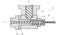
- the die 11 in FIG. 2 includes first rubber introduction members 11a and 11b that guide the color rubber member 1a extruded from the extrusion portion of the multiple extruder 10, and the color rubber member 1a that is guided by the first rubber introduction members 11a and 11b. Is provided in a direction perpendicular to the flow direction of the second, and the second portion for guiding the coated rubber member 1b extruded from another extrusion portion of the multiple extruder 10 to a flow path different from the color rubber member 11a in the first rubber introduction member 11b.
- the color rubber member 1a and the covering rubber member 1b are guided from the rubber introducing members 11c and 11d and the first rubber introducing member 11b, and the surface of the color rubber member 1a is concentrically covered with the covering rubber member 1b. And a base member 11e for discharging the rubber material 1.
- a composite rubber material is formed from two or more kinds of rubber materials including a color rubber material and a coated rubber material by an extrusion process, which is simultaneously extruded using a multiple extruder illustrated in FIG.
- the rubber material can be entirely covered on the surface of the color rubber material.
- a composite rubber material that is coated with a concentric coating rubber in a color rubber shape is formed into a string shape, thereby obtaining a composite rubber material having a minimum cross section. It is possible to manufacture a rubber member having a desired member shape.
- the covering rubber material has a property of masking the color rubber material and preventing contamination. Since the covering rubber material has such characteristics, the effect of preventing contamination as expected in the present invention can be reliably obtained.
- the properties of masking and preventing contamination include, for example, the material of the coated rubber material may have chemical properties that mask and prevent contamination, and the thickness of the coated rubber material is masked and May have physical properties to prevent contamination. The adjustment of these materials and the adjustment of the thickness may be performed alone or in combination to prevent masking and contamination. When the material of the covering rubber material is not sufficient for masking and prevention of contamination, it is necessary to increase the thickness of the covering rubber material. Therefore, it is preferable to adjust the material.
- 10 to 100 parts by weight of non-contaminating butyl rubber as a stabilizer in the polymer component as disclosed in JP-A-7-228727 as a contamination preventing composition is used.
- An antifouling composition comprising 10 to 150 parts by weight of a white filler, and an antifouling composition comprising 30 to 100 parts by weight of non-fouling butyl rubber as a stabilizer in the polymer component;
- the butyl rubber is an isobutylene-isoprene copolymer, chlorinated butyl rubber, or brominated butyl rubber.
- the thickness of the coated rubber material in one example, can be set to 0.2 to 3.0 mm when the above-described antifouling composition is used.
- the thickness of the coated rubber can be adjusted according to the extrusion speed of the coated rubber material in the multiple extruder and the shape of the die through which the coated rubber material is extruded.
- the cross-sectional shape of the base can be concentric, but is not limited to the concentric shape, and is a cross-sectional shape that approximates the line of the sidewall portion using the color rubber material and the tread wear indicator of the tread portion. You can also.
- the method of forming the composite rubber material by coating the coated rubber material with the color rubber material is not limited to the case of extruding the coated rubber material.
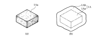
- the extruded color rubber material is cut to a predetermined length to obtain a block-shaped color rubber material 1Aa having a predetermined size as shown in FIG.
- the composite rubber material 1A can also be formed by wrapping the color rubber material 1Aa with the covering rubber material 1Ab (FIG. 5B).
- the covering rubber material for wrapping the color rubber for example, a sheet-like covering rubber material formed by rolling can be used as the covering rubber material for wrapping the color rubber.
- the material and thickness of the sheet-like covering rubber material can be the same as those described above in order to have a characteristic of masking the color rubber material and preventing contamination.
- the block-shaped composite rubber material 1A as shown in FIG. 3 can be applied to, for example, a tread wear indicator formed in a tread portion of a pneumatic tire. However, it is not limited to the use of the tread wear indicator.
- a composite rubber material in which a coated rubber material is coated with a color rubber material can be incorporated into a sidewall member or a tread member as it is, but the composite rubber material is rolled with at least a pair of rollers to deform the cross-sectional shape of the composite rubber material. You can also
- FIG. 4 shows a schematic perspective view of an example of the rolling device 20.
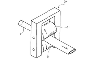
- the rolling device 20 has at least a pair of rollers 21 and flattens the string-like composite rubber material 1 by passing the composite rubber material 1 through a gap formed between these rollers.
- the composite rubber material By rolling the composite rubber material with at least a pair of rollers to deform the cross-sectional shape of the composite rubber material, it can be formed into a simple cross-sectional shape that is easy to manufacture when forming the composite rubber material by extrusion or the like. Further, by subsequent rolling, various cross-sectional shapes suitable for the application of the composite rubber material can be obtained.
- the composite rubber materials 1B to 1F having various cross-sectional shapes shown in FIGS. 5B to 5F are cross sections of gaps formed between the rollers as seen in the cross section including both rotation axes of the roller pair that performs rolling. It can be obtained by rolling using a roller having a specific outer shape such that the shape becomes a specific cross-sectional shape that approximates the cross-sectional shape of FIGS.
- the composite rubber material having a circular cross section is simply flattened by rolling, it may be rolled using a normal rolling device in which cylindrical roller pairs are arranged so that their rotational axes are parallel to each other.
- a plurality of roller pairs are arranged on a rolling line, and each roller pair has a roller shape that is different from each other. It can also have a cross-sectional shape.
- the composite rubber material having a rubber temperature easily deformed may be rolled immediately after the composite rubber material is formed by extrusion or the like.
- the composite rubber material having a lowered rubber temperature may be rolled after reheating.
- the composite rubber material not subjected to rolling or subjected to rolling can be used for manufacturing a white line of a sidewall portion of a pneumatic tire.
- this white line in the manufacturing process of the pneumatic tire, before the tire assembly process using the tire molding drum, pre-assembly with the sidewall member is performed on the extrusion train of the sidewall member, so-called preassembly is performed. be able to.
- FIG. 6 shows a schematic perspective view of an example of a conveyor in an extrusion train of sidewall members for performing pre-assembly.
- the illustrated conveyor 30 includes a plurality of rotatable rollers 31, and the rotation axes of the rollers 31 are arranged so as to be parallel to each other.
- the extruded long sidewall member 2 is conveyed in one direction by the rotation of each roller 31 in contact with the sidewall member 2 on the conveyor 30.
- an extruder 10 for extruding the composite rubber material 1 is provided on the conveyed sidewall member 2.
- the extruder 10 schematically shows only the head portion that extrudes the composite rubber material 1.
- This extruder 10 is preferably the multiple extruder described above, and is disposed close to the surface of the sidewall member 2 where the discharge port of the die continuously moves on the conveyor 30. Shall. In this drawing, for ease of understanding, only one of the two sidewall members 2 continuously moving on the conveyor 30 is provided with one multiple extruder 10. However, the multiple extruder 10 can be disposed on each of the two sidewall members 2.
- a roller 20A that presses the composite rubber material 1 extruded from the extruder 10 to deform the cross-sectional shape of the composite rubber material 1 into a flat shape is provided in the vicinity of the extruder 10.
- the extrusion speed of the composite rubber material 1 from the extruder 10 in the conveyor 30 and the speed of the conveyor 30 that moves the sidewall member 2 can be the same, and are constant so that both speeds are different.
- the cross-sectional shape of the composite rubber material 1 can be transformed into a shape suitable for the molding process.
- the composite rubber material 1 extruded from the extruder, particularly the multiple extruder 10, and the sidewall member 2 are pre-assembled and pre-assembled. Therefore, a pneumatic tire can be manufactured with high efficiency.
- the width of the color line in the manufactured pneumatic tire is preferably 10 mm or less. However, since it is not meaningful to form a color line if the width of the color line is too narrow, the color line is preferably 1 mm or more. A more preferable range is 3 to 8 mm.
- the composite rubber material not subjected to rolling or subjected to rolling can be used not only for the production of a white line in the sidewall portion of a pneumatic tire but also for the production of a tread wear indicator in the tread portion.
- a tread wear indicator in the case of manufacturing the tread wear indicator, in the manufacturing process of the pneumatic tire, before the tire assembly process using the tire molding drum, the tread member is pre-assembled with the tread member on the extruded train of the tire, so-called pre-assembly is performed. Can do.
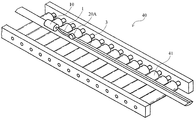
- FIG. 7 shows a schematic perspective view of an example of a conveyor in an extrusion train of a tread member that performs pre-assembly.
- the illustrated conveyor 40 can have the same configuration as the conveyor 30 illustrated in FIG. 6, and includes a plurality of rotatable rollers 41, and the rotation axes of the rollers 41 are arranged so as to be parallel to each other. ing.
- the extruded long tread member 3 is conveyed in one direction by rotation of each roller 31 in contact with the tread member 3 on the conveyor 40.
- an extruder 10 for extruding the composite rubber material is provided on the tread member 3 to be conveyed.
- the extruder 10 schematically shows only the head portion that extrudes the composite rubber material 1.
- the extruder 10 is preferably a multiple extruder as described above, in which the discharge port of the die is arranged close to the surface of the tread member 3 that continuously moves on the conveyor 40.
- a roller 20 ⁇ / b> A that presses the composite rubber material 1 extruded from the extruder 10 to deform the cross-sectional shape of the composite rubber material 1 into a flat shape is provided in the vicinity of the extruder 10.
- the composite rubber material 1 extruded from the extruder, in particular, the multiple extruder 10, and the tread member 3 are pre-assembled and pre-assembled, thereby performing a tread member.
- the composite rubber material is a groove formed on the tread portion of the manufactured pneumatic tire. It is preferable that it is embedded at the bottom of the.
- the tread wear indicator may be formed at the groove bottom portion of the tread and may be formed at the rib portion or the block portion of the tread. In any case, the tread wear indicator can be manufactured using a composite rubber material. But it is more preferable to form in the groove bottom part of a tread from a viewpoint of tread wear performance.
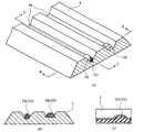
- FIG. 8 (a) shows a schematic perspective view of an example of a tread portion of a pneumatic tire in which a tread wear indicator is formed at the groove bottom of the tread.
- 8B shows a cross-sectional view taken along line BB in FIG. 8A
- FIG. 8C shows a cross-sectional view taken along line CC in FIG. 8A.
- a tread wear indicator 5A and a tread wear indicator 5B are embedded in the bottom portion of the tread groove 4a.
- the composite rubber material 1G is embedded in the groove bottom portion of the tread groove 4a of the tread portion 4 over the entire circumference in the tire circumferential direction, and is partially raised from the groove bottom portion at a predetermined height.
- This is an example of a tread wear indicator 5A.
- the tread wear indicator 5B is an example in which the block-shaped composite rubber material 1H having a predetermined length is provided so as to rise from the bottom of the groove, thereby forming the tread wear indicator 5B.
- different tread wear indicators 5A and tread wear indicators 5B are provided in one tread portion 4. Normally, the tread wear indicator 5A and the tread wear indicator 5B are provided. A tread wear indicator of any kind of the indicator 5B may be provided.
- FIG. 9 shows a schematic cross-sectional view of an example of a tread portion of a pneumatic tire in which a tread wear indicator is formed on a block portion or a rib portion of the tread.
- the tread wear indicator 5 ⁇ / b> C is a tread wear indicator 5 ⁇ / b> C because the block-shaped composite rubber material 1 ⁇ / b> H having a predetermined length is embedded in the block portion or the rib portion of the tread portion 6 at a predetermined depth from the surface thereof.
- the tread wear indicator 5D is a tread when the composite rubber material 1G is embedded in the block portion or rib portion of the tread portion 6 at a predetermined depth from the surface over the entire circumference in the tire circumferential direction or partially. This is an example of a wear indicator 5D.
- tread wear indicators 5C and tread wear indicators 5D are provided in one tread portion 6. Normally, the tread wear indicator 5C and the tread wear indicator 5C are provided. A treadwear indicator of any kind of the indicator 5D may be provided.
- the red wear indicator is formed at the groove bottom of the tread as shown in FIG. 8 or the rib or block of the tread as shown in FIG. And embedded in a part of the entire circumference of the tread.
- the tread wear indicator can be manufactured using a composite rubber material.
- the composite rubber material when embedded in a part of the entire circumference of the tread, the composite rubber material was processed into a block shape of a predetermined length, and this block-shaped composite rubber material was engraved on the tire molding die. It takes time and effort to match the position of the tread wear indicator display. Therefore, it is preferable that the composite rubber material is embedded over the entire circumference of the tread rather than being embedded in a part of the entire circumference of the tread.
- the composite rubber material when used for manufacturing a tread wear indicator formed on the tread portion of the pneumatic tire, it is more preferable that the composite rubber material is a tread of the manufactured pneumatic tire. This is a case where the part is buried in the groove bottom of the tread groove over the entire circumference of the tread.
- the embodiment of the pneumatic tire manufacturing apparatus of the present invention includes a color rubber material having a color different from the black rubber material by carbon black and the color rubber material.
- a train that conveys another rubber material is provided with a multiple extruder that simultaneously extrudes the coated rubber material to be coated to obtain a composite rubber material.
- a pneumatic tire manufacturing apparatus including a multiple extruder in a train can manufacture a pneumatic tire using a composite rubber material with high productivity.
- Example 1 As shown in FIG. 6, the composite rubber material was extruded onto the surface of the sidewall member conveyed on the conveyor in the extrusion train of the sidewall member using a multiple extruder, and then pressed by a roller. Thereby, the member in which the composite rubber material 1B having a cross-sectional shape as shown in FIG. 5B was formed on the surface of the sidewall member could be preassembled.
- a white rubber material was used as the color rubber material, and a rubber material that masked the color rubber material and prevented contamination was used as the covering rubber material.
- a pre-assembled rubber member for a sidewall was attached to a tire molding drum to assemble a raw tire, and then vulcanized to obtain a pneumatic tire.
- the position where the composite rubber material was buried in the sidewall portion of the obtained pneumatic tire was polished with a grinder, and the white rubber material of the composite rubber material was exposed in a line shape on the tire surface.
- the width of the line-shaped white rubber material was 8 mm.
- Example 2 As shown in FIG. 7, the composite rubber material was extruded onto the surface of the tread member conveyed on the conveyor in the extrusion train of the tread member using a multiple extruder, and then pressed by a roller. Thereby, the rubber member in which the composite rubber material 1D having a cross-sectional shape as shown in FIG. 5D was formed on the surface of the tread member could be preassembled.
- a green rubber material was used as the color rubber material, and a rubber material that masked the color rubber material and prevented contamination was used as the covering rubber material.
- a pre-assembled tread rubber material was attached to a tire molding drum to assemble a raw tire, and then vulcanized to obtain a pneumatic tire.
- a composite rubber material was embedded in the groove bottom portion of the tread groove in the tread portion over the entire circumference in the tire circumferential direction.
Landscapes
- Engineering & Computer Science (AREA)
- Mechanical Engineering (AREA)
- Tyre Moulding (AREA)
- Extrusion Moulding Of Plastics Or The Like (AREA)
Abstract
空気入りタイヤのサイドウォール部の装飾又は文字情報表示や、トレッド部のトレッドウエアインジケータとして用いられるカラーゴム材の色の汚染を、タイヤ重量の増加を抑制して効果的に防止することのできる空気入りタイヤの製造方法を提供する。 本発明の空気入りタイヤの製造方法は、カーボンブラックによる黒色のゴム材とは異なる色を有するカラーゴム材1aとこのカラーゴム材1aを被覆する被覆ゴム材1bとを含む2種類以上のゴム材よりなる複合ゴム材1を形成する工程を含む。
Description
本発明は空気入りタイヤの製造方法及び製造装置に関する。
空気入りタイヤは、通常はタイヤの強度を向上させるために含有されるカーボンブラックに由来した黒色を有している。このカーボンブラックによる黒色のゴム材とは異なる色を有するカラーゴム材が空気入りタイヤに用いられることがある。例えば、このタイヤのサイドウォールの表面に、ライン状または文字状に白色ゴムからなる部分を形成して、タイヤの美観を向上させたり情報を表示させたりすることが行われている。このような白色ゴムからなる部分としてライン状白色ゴム部分を形成するための、空気入りタイヤの製造方法の一例では、製造工程中に次のような工程を行っていた。
タイヤの製造工程中のサイドウォール用のゴム部材を成形する際に、押出機を用いて、黒色のゴム材よりなるサイドウォール用のゴム部材の表面の一部に白色ゴム材が積層されるように押出す。押出した後は、サイドウォール用のゴム部材上に積層された白色ゴム材を覆うように被覆ゴムを貼り付けてから、タイヤ成型ドラムを用いて複数のタイヤ部材を組み立てるタイヤ成型工程を行う。このタイヤ成型工程では、サイドウォール用のゴム部材を、そのサイドウォールの周長に適合した長さで切断し、かつ両端部を接合して円筒状のサイドウォール形状とする。組み立てられた生タイヤを加硫し、加硫後は、タイヤのサイドウォール部において白色ゴム材を覆う被覆ゴムを、グラインダー等で研磨除去することにより、白色ゴム材をサイドウォールの表面に露出させるようにしていた。
タイヤ用のゴム部材等を押出し成形するための多重押出機に関し、インナーライナゴムと、チェーファゴムとを同時に押出し成形するものがある(特許文献1)。
しかしながら、上述のように押出し成形により白色ゴム材を黒色ゴム材上に積層形成した場合には、白色ゴム材の色が周囲の黒色ゴム材で汚染されることが避けられない。そのため、汚染される分を見越して白色ゴム材の部分の範囲を大きくした場合には、結果的に最終形状としてのラインや識別用文字等に必要な白色ゴムの部分の体積に対して、原料としての白色ゴムは数倍の量が必要となる。そのため、高価な白色ゴムを大量に要することによってタイヤのコスト上昇を招くおそれがある。また、白色ゴム材は、耐久性が通常の黒色ゴム材に比べて劣るため、白色ゴム材を大量に用いるとタイヤ全体としての耐久性が低下するおそれがある。この耐久性を、黒色ゴムのみの空気入りタイヤと同等の性能とするためには、黒色ゴムのみの空気入りタイヤよりも多くのゴム量を必要となり、空気入りタイヤの重量が増大するばかりでなく、タイヤのコスト上昇を招く。
また、空気入りタイヤにおいてカラーゴム材は、上述したサイドウォール部のみならず、路面と接するトレッド部にも使用されることがある。例えば、このトレッド部には、そのトレッド部の摩耗度を視認できるように、当該トレッドに形成された溝の底部に、トレッドウエアインジケータと呼ばれる溝深さが他の部分よりも浅い部分が形成されている。
このトレッドウエアインジケータにカラーゴム材が用いられているタイヤがある(特許文献2、特許文献3)。また、タイヤのファッション性を向上させるために、トレッド部の溝底にカラーゴムを用いたタイヤがある(特許文献4)。
このトレッドウエアインジケータにカラーゴム材が用いられているタイヤがある(特許文献2、特許文献3)。また、タイヤのファッション性を向上させるために、トレッド部の溝底にカラーゴムを用いたタイヤがある(特許文献4)。
しかしながら、このトレッド部に用いられるカラーゴム材も、黒色のゴム材と積層して形成されるために、サイドウォール部に用いられる白ゴム材と同様の問題、すなわちカラーゴムの汚染や、耐久性の低下を見越して製造する場合のタイヤ重量の増加や、コスト上昇の問題が生じる。
本発明は、上記の問題を有利に解決するものであり、カラーゴム材を備える空気入りタイヤのカラーゴムに対する色の汚染を防止することのできる空気入りタイヤの製造方法及びその製造に用いて好適な製造装置を提供することを目的とする。
本発明の空気入りタイヤの製造方法は、カーボンブラックによる黒色のゴム材とは異なる色を有するカラーゴム材とこのカラーゴム材を被覆する被覆ゴム材とを含む2種類以上のゴム材よりなる複合ゴム材を形成する工程を含むことを特徴とする。
本発明の空気入りタイヤの製造方法においては、複合ゴム材を形成する工程を、カラーゴム材と被覆ゴム材とを含む2種類以上のゴム材を、多重押出機を用いて同時に押出す押出し工程とすることができる。また、被覆ゴム材は、前記カラーゴム材をマスキングしかつ、汚染防止する特性を有するものであることが好ましい。
更に、本発明の空気入りタイヤの製造方法は、複合ゴム材を形成する工程により得られた紐状の複合ゴム材を、少なくとも一対のローラーによって圧延して当該複合ゴム材の断面形状を変形する工程を含むことができる。また、複合ゴム材を形成する工程により得られた複合ゴム材を、タイヤ成型ドラムを用いたタイヤ組み立て工程の前に、サイドウォール部材の押出しトレーン上においてサイドウォール部材と予め組み立てる工程や、複合ゴム材を形成する工程により得られた複合ゴム材を、タイヤ成型ドラムを用いたタイヤ組み立て工程の前に、トレッド部材の押出しトレーン上においてトレッド用部材と予め組み立てる工程を更に含むことができる。
また、本発明の空気入りタイヤの製造方法は、カラーゴム材が、空気入りタイヤのサイドウォール部の表面に形成されるカラーライン用のものであり、製造された空気入りタイヤにおけるカラーラインの幅が10mm以下であるものとすることができ、また、カラーゴム材が、空気入りタイヤのトレッド部に形成されるトレッドウエアインジケータ用のものであり、製造された空気入りタイヤのトレッド部において、当該トレッドに形成される溝の底部に位置して埋設されたもの、及び/又は空気入りタイヤのトレッド部において、当該トレッドの全周にわたって埋設されるものとすることができる。
本発明の空気入りタイヤの製造装置は、カーボンブラックによる黒色のゴム材とは異なる色を有するカラーゴム材とこのカラーゴム材を被覆する被覆ゴム材とを同時に押出して複合ゴム材を得る多重押出機を、別のゴム材を搬送するトレーンに備えることを特徴とする。
本発明の空気入りタイヤの製造方法によれば、通常の黒色のゴム材とは異なる色を有するカラーゴム材が被覆ゴム材によって被覆されるように、複合ゴム材を形成することから、この複合ゴム材の被覆ゴム材が、カラーゴム材への色の汚染に対する障壁となることにより、この汚染を防止することができる。したがって、通常の黒色のゴム材とは明瞭に区別し得るカラーゴム材を備える空気入りタイヤを、カラーゴム材の使用量の増大によるタイヤ重量の大幅な増大を招くことなく製造することができる。
本発明の空気入りタイヤの製造装置によれば、カラーゴム材を被覆するように被覆ゴム材を同時に押出すことができる多重押出機を備えることから、重量の増大を来すことなく、通常の黒色のゴム材とは明瞭に区別し得るカラーゴム材を空気入りタイヤを、容易に製造することが可能となる。
以下、本発明の実施の形態について、図面を用いつつ、より具体的に説明する。
本発明の空気入りタイヤの製造方法は、カーボンブラックによる黒色のゴム材とは異なる色を有するカラーゴム材とこのカラーゴム材を被覆する被覆ゴム材とを含む2種類以上のゴム材よりなる複合ゴム材を形成する工程を含む。
図1に、押出機10のダイ11より押し出されて得られた複合ゴム材1の一例を模式的に示す。図1に示した複合ゴム材1は、カラーゴム材1aと、このカラーゴム材1aを被覆する被覆ゴム材1bとからなる紐状の複合ゴム材である。
本発明においてカラーゴム材は、例えば、空気入りタイヤのサイドウォール部に形成される白色のラインや文字情報等に用いられ、また、トレッド部のトレッドウエアインジケータに適用され得るものである。また、カラーゴム材は、サイドウォール部やトレッド部用に用いられる通常のゴム部材の黒色とは異なる色を有するゴム材のことをいい、また、カーボンブラック含有量の相違により通常のゴム部材と明度が異なるゴム材を含む。このようなカラーゴム材には、公知のカラーゴム材が適合され得る。
カラーゴム材は、空気入りタイヤのサイドウォール部の白色のラインや、トレッド部の全周にわたって形成されるトレッドウエアインジケータに適用する場合には、タイヤ成型ドラムで生タイヤを組み立てる前の形状として、所定の長さを有する紐状とすることができ、それは押出しにより形成することができる。
被覆ゴム材は、カラーゴム材を覆って形成される。カラーゴム材が押出しにより紐状に形成されたものである場合には、この紐状のカラーゴム材の表面を覆うように被覆ゴム材が形成される。この場合、本発明で所期したカラーゴムの色の汚染防止のためには、被覆ゴム材は、紐状のカラーゴム材の表面を全面的に被覆するのが好ましい。
カラーゴム材とこのカラーゴム材を被覆する被覆ゴム材とを含む2種類以上のゴム材より形成された複合ゴム材を用いて空気入りタイヤを製造することにより、空気入りタイヤにおける複合ゴム材の被覆ゴム材が、カラーゴム材と、空気タイヤを構成する部材として用いられる黒色のゴム部材との間に介在することになる。したがって、この被覆ゴム材は、カラーゴム材への色の汚染に対する障壁となる。このことにより、この被覆ゴム材を具備する複合ゴムを使用した空気入りタイヤは、カラーゴム材の非汚染距離を確保するために多量のカラーゴムを必要としない。よって、色の汚染がされずに通常の黒色のゴム材とは明瞭に区別し得るカラーゴム材を備える空気入りタイヤを、カラーゴム材の使用量の増大によるタイヤ重量の増大を招くことなく製造することができる。
被覆ゴム材は、カラーゴム材が押出して形成されるものである場合には、この被覆ゴム材もまた、押出して形成して、複合ゴム材を、押出しにより形成することができる。押出しは、長尺な成形体を連続的に形成することができるので、得られた複合ゴム材を所定長さで切断することにより、空気入りタイヤのサイドウォール部やトレッド部用の部材を生産性高く製造することができる。そのため、当該複合ゴム材を、これらのサイドウォール部やトレッド部用の部材の一部に適用してタイヤを製造するのに押出しによる形成することは有利である。
被覆ゴム材の押出しは、カラーゴム材の押出しの後に、得られた紐状の連続的なカラーゴム材、又は所定長さに切断されたカラーゴム材を、この被覆ゴム材で被覆するように押出すこともできるが、多重押出機を用いて、カラーゴム材と同時に、かつ、当該カラーゴムと同心に、被覆ゴム材を押出すことが、好ましい。多重押出機は、例えばクロスヘッド型のダイを有し、複数のゴム材を同心円状に押出すことができる押出機とすることができる。
多重押出機の一例を、その先端部に設けられたクロスヘッド型のダイの模式的な断面図で図2に示す。図2のダイ11は、多重押出機10の押出部から押出されたカラーゴム部材1aを導く第一ゴム導入部材11a、11bと、この第一ゴム導入部材11a、11bにより導かれるカラーゴム部材1aの流動方向とは垂直方向に設けられ、多重押出機10の別の押出部から押出された被覆ゴム部材1bを第一ゴム導入部材11bにおけるカラーゴム部材11aとは別の流路に導く第二ゴム導入部材11c、11dと、第一ゴム導入部材11bからカラーゴム部材1a及び被覆ゴム部材1bが導かれ、カラーゴム部材1aの表面に被覆ゴム部材1bが同心円状に被覆されるようにして複合ゴム材1を吐出する口金部材11eとを備えている。
図2を一例とする多重押出機を用いて同時に押出す、押出し工程によって、カラーゴム材と被覆ゴム材とを含む2種類以上のゴム材から複合ゴム材を形成することにより、生産性よく被覆ゴム材をカラーゴム材の表面に全面的に被覆することができる。
また、多重押出機を用いてカラーゴム状に同心円状に被覆ゴムが被覆された複合ゴム材を、紐状に形成することにより、最小断面の複合ゴム材を得て、後で述べるように種々の所望の部材形状のゴム部材を製造することが可能となる。
被覆ゴム材は、カラーゴム材をマスキングしかつ、汚染防止する特性を有するものとすることが好ましい。被覆ゴム材が、このような特性を有することにより、本発明で所期した汚染防止の効果を確実に得ることができる。マスキングしかつ、汚染防止する特性には、例えば、被覆ゴム材の材質が、マスキングしかつ、汚染防止する化学的特性を有する場合があり、また、被覆ゴム材の厚さが、マスキングしかつ、汚染防止する物理的特性を有する場合がある。これらの材質の調整や厚さの調整を単独で、又は併用してマスキング及び汚染防止をすればよい。被覆ゴム材の材質がマスキング及び汚染防止に十分でない場合には、被覆ゴム材の厚さを増大させる必要があるため、材質を調整することは好ましい。
被覆ゴム材の材質に関して、一例では、汚染防止組成物として特開平7-228727号公報に開示されているような、ポリマ-成分中、安定剤として非汚染性のブチルゴムを10~100重量部を有し、これに白色充填剤を10~150重量部を含有させた汚染防止組成物、このポリマ-成分中、安定剤として非汚染性のブチルゴムを30~100重量部とした汚染防止組成物、このブチルゴムがイソブチレン-イソプレン共重合体、塩素化ブチルゴム、臭素化ブチルゴムである汚染防止組成物がある。
上記被覆ゴム材の厚さに関して、一例では、上記のような汚染防止組成物を用いた場合として、0.2~3.0mmの厚さとすることができる。
被覆ゴムの厚さの調整は、上述した多重押出機を用いた場合には、当該多重押出機における被覆ゴム材の押出速度と、被覆ゴム材が押出される口金の形状により行うことができる。口金の断面形状は、同心円状のものとすることができるが、同心円状のものに限定されず、カラーゴム材を用いるサイドウォール部のラインやトレッド部のトレッドウエアインジケータに近似した断面形状とすることもできる。
被覆ゴム材をカラーゴム材に被覆して複合ゴム材を形成する方法は、この被覆ゴム材を押出す場合に限られない。例えば、押出されたカラーゴム材を所定の長さで切断して、図3に示すように、所定サイズのブロック形状のカラーゴム材1Aaとした(同図(a))後、このブロック形状のカラーゴム材1Aaを被覆ゴム材1Abで包むことにより複合ゴム材1Aを形成する(同図(b))こともできる。
この場合にカラーゴムを包む被覆ゴム材は、例えば圧延により成形されたシート状の被覆ゴム材を用いることができる。シート状の被覆ゴム材の材質や厚さは、カラーゴム材をマスキングしかつ、汚染防止する特性を有するために先に述べた特性と同様とすることができる。図3に示したようなブロック形状の複合ゴム材1Aは、例えば空気入りタイヤのトレッド部に形成されるトレッドウエアイジケータに適用することができる。もっとも、トレッドウエアインジケータの用途に限定されるものではない。
被覆ゴム材をカラーゴム材に被覆した複合ゴム材は、そのままサイドウォール部材やトレッド部材に組み込むこともできるが、複合ゴム材を少なくとも一対のローラーによって圧延して当該複合ゴム材の断面形状を変形することもできる。
図4に圧延装置20の一例の模式的な斜視図を示す。圧延装置20は、少なくとも一対のローラー21を有し、これらのローラー間に形成されたギャップに複合ゴム材1を通過させることにより紐状の複合ゴム材1を扁平にする。
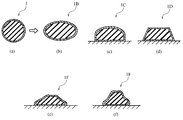
図5に、種々の断面形状を有する複合ゴム材の例を示す。図5(a)は、押出したままで圧延を行わなかった、円形断面の複合ゴム材1を示し、図5(b)~(f)は、図5(a)の複合ゴム材1を圧延した後の、種々の断面形状になる複合ゴム材1B~1Fを示している。図5(b)~(f)は、圧延して得られる複合ゴム材の例示であり、本発明はこれらの断面形状に限定されず、複合ゴム材中のカラーゴム材が空気入りタイヤに用いられる用途に応じて適宜に断面形状を定めることができる。
複合ゴム材を、少なくとも一対のローラーで圧延して当該複合ゴム材の断面形状を変形させることにより、押出し等による複合ゴム材の形成時には、製造が容易な簡単な断面形状に成形することができ、また、その後の圧延で、複合ゴム材の用途に適合する種々の断面形状とすることができる。
図5(b)~(f)に図示した各種断面形状の複合ゴム材1B~1Fは、圧延を実施するローラー対の両回転軸を含む断面で見た、ローラー間に形成されたギャップの断面形状が、図5(b)~(f)の断面形状に近似した特定の断面形状になるような、特定の外形を有するローラーを用いて圧延することによって得ることができる。もっとも、円形断面の複合ゴム材を圧延で単に扁平にする場合は、円筒形状のローラー対を互いの回転軸が平行になるように配置した通常の圧延装置を用いて圧延すればよい。また、複数のローラー対を圧延ライン上に配列させて備え、各ローラー対はローラー形状が異なるものとした圧延装置を用いて、複合ゴム材を、これらのローラー対で順次に圧延して所定の断面形状にすることもできる。
複合ゴム材を圧延する時期は、複合ゴム材を押出し等により形成した直後に、変形し易いゴム温度を有している複合ゴム材を圧延してもよく、また、押出し等の後で、いったんゴム温度が低下した複合ゴム材を、再加熱してから圧延してもよい。
圧延を施さない、又は圧延を施した複合ゴム材は、空気入りタイヤのサイドウォール部の白色ラインの製造のために用いることができる。この白色ラインの製造の場合、空気入りタイヤの製造過程において、タイヤ成型ドラムを用いたタイヤ組み立て工程の前に、サイドウォール部材の押出しトレーン上においてサイドウォール部材と予め組み立てること、いわゆるプリアセンブルを行うことができる。
図6に、プリアセンブルを実施するサイドウォール部材の押出しトレーンにおけるコンベアの一例の模式的な斜視図を示す。図示したコンベア30は、回動可能な複数のローラー31を備え、各ローラー31の回転軸が、互いに平行になるように配列されている。押し出された長尺のサイドウォール部材2は、コンベア30上で当該サイドウォール部材2と接する各ローラー31の回転によって一方向に搬送される。
サイドウォール部材の押出しトレーンのコンベア30において、搬送されるサイドウォール部材2上に、複合ゴム材1を押出すための押出機10が設けられている。図6では、押出機10は模式的に複合ゴム材1を押出すヘッド部分のみを示している。この押出機10は、好ましくは、先に説明した多重押出機であって、ダイの吐出口がコンベア30上で連続的に移動するサイドウォール部材2の表面に向けて近接して配設されるものとする。なお、この図面では、理解を容易にするためにコンベア30上を連続的に移動する2本のサイドウォール部材2のうちの1本のみに1個の多重押出機10が配設されているように描かれているが、2本のサイドウォール部材2のそれぞれに多重押出機10を配設することができる。
また、押出機10から押し出された複合ゴム材1を押圧して複合ゴム材1の断面形状を扁平に変形させるローラー20Aが押出機10の近傍に設けられている。
コンベア30における押出機10からの複合ゴム材1の押出速度と、サイドウォール部材2を移動させるコンベア30の速度とは、同じとすることができるし、また、両者の速度が異なるように、一定の割合で調整することにより、複合ゴム材1の断面形状を、成型工程に適した形状に変形させることもできる。
このようにサイドウォール部材2を搬送するコンベア30上において、押出機、特に多重押出機10から押し出された複合ゴム材1とサイドウォール部材2とを予め組み立てる、プリアセンブルを行うことにより、サイドウォール用の部材を一度に生産できるので、高効率で空気入りタイヤを製造することができる。
複合ゴム材を空気入りタイヤのサイドウォール部の白色ラインの製造のために用いた場合に、製造された空気入りタイヤにおけるカラーラインの幅を10mm以下とすることが好ましい。もっとも、カラーラインの幅があまりにも狭いとカラーラインを形成する意義がなくなるので、カラーラインは1mm以上であることが好ましい。より好ましい範囲は3~8mmとすることができる。
圧延を施さない、又は圧延を施した複合ゴム材は、空気入りタイヤのサイドウォール部の白色ラインの製造のためばかりでなく、トレッド部のトレッドウエアインジケータの製造のために用いることができる。このトレッドウエアインジケータの製造の場合、空気入りタイヤの製造過程において、タイヤ成型ドラムを用いたタイヤ組み立て工程の前に、トレッド部材の押出しトレーン上においてトレッド部材と予め組み立てること、いわゆるプリアセンブルを行うことができる。
図7に、プリアセンブルを実施するトレッド部材の押出しトレーンにおけるコンベアの一例の模式的な斜視図を示す。図示したコンベア40は、図6に示したコンベア30と、同じ構成とすることができ、回動可能な複数のローラー41を備え、各ローラー41の回転軸が、互いに平行になるように配列されている。押し出された長尺のトレッド部材3は、コンベア40上で当該トレッド部材3と接する各ローラー31の回転によって一方向に搬送される。
トレッド部材の押出しトレーンのコンベア40において、搬送されるトレッド部材3上に、複合ゴム材を押出すための押出機10が設けられている。図7では、押出機10は模式的に複合ゴム材1を押出すヘッド部分のみを示している。この押出機10は、好ましくは、先に説明した多重押出機であって、ダイの吐出口がコンベア40上で連続的に移動するトレッド部材3の表面に向けて近接して配設されるものとする。また、押出機10から押し出された複合ゴム材1を押圧して複合ゴム材1の断面形状を扁平に変形させるローラー20Aが押出機10の近傍に設けられている。
コンベア40における押出機10からの複合ゴム材1の押出速度と、トレッド部材3を移動させるコンベア40の速度とは、同じとすることができるし、また、両者の速度が異なるように、一定の割合で調整することにより、複合ゴム材1の断面形状を、成型工程に適した形状に変形させることもできる。
このようにトレッド部材3を搬送するコンベア40上において、押出機、特に多重押出機10から押し出された複合ゴム材1とトレッド部材3とを予め組み立てる、プリアセンブルを行うことにより、トレッド用の部材を一度に生産できるので、高効率で空気入りタイヤを製造することができる。
複合ゴム材を空気入りタイヤのトレッド部に形成されるトレッドウエアインジケータの製造のために用いた場合に、複合ゴム材は、製造された空気入りタイヤのトレッド部において、当該トレッドに形成される溝の底部に位置して埋設されたものであることが好ましい。トレッドウエアインジケータは、トレッドの溝底部に形成される場合と、トレッドのリブ部又はブロック部に形成される場合とがあり、いずれの場合にも複合ゴム材を用いて製造することができる。もっとも、トレッドの溝底部に形成されることが、トレッド摩耗性能の観点から、より好ましい。
図8(a)に、トレッドウエアインジケータがトレッドの溝底部に形成されている空気入りタイヤのトレッド部の一例の模式的な斜視図を示す。また、図8(b)に、図8(a)のB-B線視の断面図を示し、図8(c)に、図8(a)のC-C線視の断面図を示す。図8に示す空気入りタイヤのトレッド部4には、トレッド溝4aの溝底部に、トレッドウエアインジケータ5A及びトレッドウエアインジケータ5Bが埋設されている。
トレッドウエアインジケータ5Aは、複合ゴム材1Gがトレッド部4のトレッド溝4aの溝底部に、タイヤ周方向の全周にわたって埋設され、かつ、一部分において溝底部から所定高さで隆起されていることによりトレッドウエアインジケータ5Aとなっている例である。トレッドウエアインジケータ5Bは、所定長さのブロック形状の複合ゴム材1Hが、溝底部から隆起するように設けられたことによりトレッドウエアインジケータ5Bとなっている例である。なお、図8では、本発明の理解を容易にするために、異なるトレッドウエアインジケータ5A及びトレッドウエアインジケータ5Bが一つのトレッド部4に設けられているが、通常は、トレッドウエアインジケータ5A及びトレッドウエアインジケータ5Bのいずれかの種類のトレッドウエアインジケータを設ければよい。
図9に、トレッドウエアインジケータがトレッドのブロック部又はリブ部に形成されている空気入りタイヤのトレッド部の一例の模式的な断面図を示す。図9において、トレッドウエアインジケータ5Cは、所定長さのブロック形状の複合ゴム材1Hが、トレッド部6のブロック部又はリブ部に、その表面から所定深さで埋設されたことによりトレッドウエアインジケータ5Cとなっている例である。また、トレッドウエアインジケータ5Dは、複合ゴム材1Gがトレッド部6のブロック部又はリブ部に、その表面から所定深さで、タイヤ周方向の全周にわたって、又は部分的に埋設されたことによりトレッドウエアインジケータ5Dとなっている例である。
なお、図9では、本発明の理解を容易にするために、異なるトレッドウエアインジケータ5C及びトレッドウエアインジケータ5Dが一つのトレッド部6に設けられているが、通常は、トレッドウエアインジケータ5C及びトレッドウエアインジケータ5Dのいずれかの種類のトレッドウエアインジケータを設ければよい。
レッドウエアインジケータは、図8に示したようにトレッドの溝底部に形成される場合においても、図9に示したようにトレッドのリブ部又はブロック部に形成される場合においても、トレッドの全周にわたって埋設される場合と、トレッドの全周のうちの一部に埋設される場合とがある。いずれの場合にもトレッドウエアインジケータを、複合ゴム材を用いて製造することができる。もっとも、トレッドの全周のうちの一部に埋設される場合は、複合ゴム材を所定長さのブロック形状に加工して、このブロック形状の複合ゴム材を、タイヤ成型金型に刻印されたトレッドウエアインジケータ表示の位置に合わせて手間を要する。したがって、複合ゴム材は、トレッドの全周のうちの一部に埋設されるよりも、トレッドの全周にわたって埋設されることのほうが好ましい。
以上のことから、複合ゴム材を空気入りタイヤのトレッド部に形成されるトレッドウエアインジケータの製造のために用いた場合に、より好ましいのは、複合ゴム材が、製造された空気入りタイヤのトレッド部において、当該トレッドの全周にわたって、トレッド溝の溝底部に埋設される場合である。
本発明の空気入りタイヤの製造装置の実施形態は、図6及び図7に具体的に示したように、カーボンブラックによる黒色のゴム材とは異なる色を有するカラーゴム材とこのカラーゴム材を被覆する被覆ゴム材とを同時に押出して複合ゴム材を得る多重押出機を、別のゴム材を搬送するトレーンに備えるものである。トレーンに多重押出機を備えた空気入りタイヤの製造装置は、複合ゴム材を用いた空気入りタイヤを生産性よく製造することができる。
(実施例1)
図6に示すように、サイドウォール部材の押出しトレーンにおけるコンベア上を搬送されるサイドウォール部材の表面に、多重押出機を用いて複合ゴム材を押出し、次いでローラーにより押圧した。これにより、図5(b)に示すような断面形状の複合ゴム材1Bがサイドウォール部材の表面に形成された部材をプリアセンブルすることができた。複合ゴム材には、カラーゴム材として白色ゴム材を用い、また、被覆ゴム材としてカラーゴム材をマスキングしかつ、汚染防止するゴム材を用いた。
図6に示すように、サイドウォール部材の押出しトレーンにおけるコンベア上を搬送されるサイドウォール部材の表面に、多重押出機を用いて複合ゴム材を押出し、次いでローラーにより押圧した。これにより、図5(b)に示すような断面形状の複合ゴム材1Bがサイドウォール部材の表面に形成された部材をプリアセンブルすることができた。複合ゴム材には、カラーゴム材として白色ゴム材を用い、また、被覆ゴム材としてカラーゴム材をマスキングしかつ、汚染防止するゴム材を用いた。
プリアセンブルされたサイドウォール用のゴム部材をタイヤ成型ドラムに貼り付けて生タイヤを組み立てた後、加硫して空気入りタイヤを得た。得られた空気入りタイヤのサイドウォール部における複合ゴム材が埋設されている位置をグラインダーで研磨し、複合ゴム材の白ゴム材をタイヤ表面にライン状に露出させた。ライン状の白ゴム材の幅は8mmであった。
(実施例2)
図7に示すように、トレッド部材の押出しトレーンにおけるコンベア上を搬送されるトレッド部材の表面に、多重押出機を用いて複合ゴム材を押出し、次いでローラーにより押圧した。これにより、図5(d)に示すような断面形状の複合ゴム材1Dがトレッド部材の表面に形成されたゴム部材をプリアセンブルすることができた。複合ゴム材には、カラーゴム材として緑色のゴム材を用い、また、被覆ゴム材としてカラーゴム材をマスキングしかつ、汚染防止するゴム材を用いた。
図7に示すように、トレッド部材の押出しトレーンにおけるコンベア上を搬送されるトレッド部材の表面に、多重押出機を用いて複合ゴム材を押出し、次いでローラーにより押圧した。これにより、図5(d)に示すような断面形状の複合ゴム材1Dがトレッド部材の表面に形成されたゴム部材をプリアセンブルすることができた。複合ゴム材には、カラーゴム材として緑色のゴム材を用い、また、被覆ゴム材としてカラーゴム材をマスキングしかつ、汚染防止するゴム材を用いた。
プリアセンブルされたトレッド用のゴム材をタイヤ成型ドラムに貼り付けて生タイヤを組み立てた後、加硫して空気入りタイヤを得た。得られた空気入りタイヤは、トレッド部のトレッド溝の溝底部に、タイヤ周方向の全周にわたって複合ゴム材が埋設されているものであった。
1 複合ゴム材
1a カラーゴム材
1b 被覆ゴム材
2 サイドウォール部材
3 トレッド部材
10 多重押出機
20 圧延機
30,40 コンベア
1a カラーゴム材
1b 被覆ゴム材
2 サイドウォール部材
3 トレッド部材
10 多重押出機
20 圧延機
30,40 コンベア
Claims (10)
- カーボンブラックによる黒色のゴム材とは異なる色を有するカラーゴム材とこのカラーゴム材を被覆する被覆ゴム材とを含む2種類以上のゴム材よりなる複合ゴム材を形成する工程を含むことを特徴とする空気入りタイヤの製造方法。
- 前記複合ゴム材を形成する工程が、カラーゴム材と被覆ゴム材とを含む2種類以上のゴム材を、多重押出機を用いて同時に押出す押出し工程である、請求項1記載の空気入りタイヤの製造方法。
- 前記被覆ゴム材は、前記カラーゴム材をマスキングしかつ、汚染防止する特性を有するものである請求項1記載の空気入りタイヤの製造方法。
- 前記複合ゴム材を形成する工程により得られた紐状の複合ゴム材を、少なくとも一対のローラーによって圧延して当該複合ゴム材の断面形状を変形する工程を含む請求項1記載の空気入りタイヤの製造方法。
- 前記複合ゴム材を形成する工程により得られた複合ゴム材を、タイヤ成型ドラムを用いたタイヤ組み立て工程の前に、サイドウォール部材の押出しトレーン上においてサイドウォール部材と予め組み立てる工程を含む請求項1記載の空気入りタイヤの製造方法。
- 前記カラーゴム材が、空気入りタイヤのサイドウォール部の表面に形成されるカラーライン用のものであり、製造された空気入りタイヤにおけるカラーラインの幅が10mm以下である請求項1記載の空気入りタイヤの製造方法。
- 前記複合ゴム材を形成する工程により得られた複合ゴム材を、タイヤ成型ドラムを用いたタイヤ組み立て工程の前に、トレッド部材の押出しトレーン上においてトレッド用部材と予め組み立てる工程を含む請求項1に記載の空気入りタイヤの製造方法。
- 前記カラーゴム材が、空気入りタイヤのトレッド部に形成されるトレッドウエアインジケータ用のものであり、製造された空気入りタイヤのトレッド部において、当該トレッドに形成される溝の底部に位置して埋設されたものである請求項1に記載の空気入りタイヤの製造方法。
- 前記カラーゴム材が、空気入りタイヤのトレッド部に形成されるトレッドウエアインジケータ用のものであり、製造された空気入りタイヤのトレッド部において、当該トレッドの全周にわたって埋設されるものである請求項1に記載の空気入りタイヤの製造方法。
- カーボンブラックによる黒色のゴム材とは異なる色を有するカラーゴム材とこのカラーゴム材を被覆する被覆ゴム材とを同時に押出して複合ゴム材を得る多重押出機を、別のゴム材を搬送するトレーンに備えることを特徴とする空気入りタイヤの製造装置。
Applications Claiming Priority (2)
| Application Number | Priority Date | Filing Date | Title |
|---|---|---|---|
| JP2010161928A JP5677776B2 (ja) | 2010-07-16 | 2010-07-16 | 空気入りタイヤの製造方法及び製造装置 |
| JP2010-161928 | 2010-07-16 |
Publications (1)
| Publication Number | Publication Date |
|---|---|
| WO2012008363A1 true WO2012008363A1 (ja) | 2012-01-19 |
Family
ID=45469366
Family Applications (1)
| Application Number | Title | Priority Date | Filing Date |
|---|---|---|---|
| PCT/JP2011/065617 Ceased WO2012008363A1 (ja) | 2010-07-16 | 2011-07-07 | 空気入りタイヤの製造方法及び製造装置 |
Country Status (2)
| Country | Link |
|---|---|
| JP (1) | JP5677776B2 (ja) |
| WO (1) | WO2012008363A1 (ja) |
Cited By (3)
| Publication number | Priority date | Publication date | Assignee | Title |
|---|---|---|---|---|
| JP2013095188A (ja) * | 2011-10-28 | 2013-05-20 | Bridgestone Corp | タイヤ |
| JP2013095189A (ja) * | 2011-10-28 | 2013-05-20 | Bridgestone Corp | タイヤ |
| JP2013095187A (ja) * | 2011-10-28 | 2013-05-20 | Bridgestone Corp | タイヤ |
Families Citing this family (3)
| Publication number | Priority date | Publication date | Assignee | Title |
|---|---|---|---|---|
| JP6055454B2 (ja) * | 2014-10-27 | 2016-12-27 | 住友ゴム工業株式会社 | ゴムストリップの製造装置及び製造方法 |
| JP7530843B2 (ja) * | 2021-01-29 | 2024-08-08 | Toyo Tire株式会社 | ゴムストリップ製造方法及びゴムストリップ製造装置 |
| JP7777429B2 (ja) * | 2021-11-22 | 2025-11-28 | Toyo Tire株式会社 | 色線を備えたトレッド部材及び該トレッド部材の製造方法 |
Citations (3)
| Publication number | Priority date | Publication date | Assignee | Title |
|---|---|---|---|---|
| JPH0338416A (ja) * | 1989-07-06 | 1991-02-19 | Bridgestone Corp | 摩耗インジゲータ付タイヤ |
| JP2010047073A (ja) * | 2008-08-20 | 2010-03-04 | Yokohama Rubber Co Ltd:The | 空気入りタイヤ |
| JP2010076218A (ja) * | 2008-09-25 | 2010-04-08 | Toyo Tire & Rubber Co Ltd | 空気入りタイヤの製造方法 |
Family Cites Families (2)
| Publication number | Priority date | Publication date | Assignee | Title |
|---|---|---|---|---|
| JP2006159570A (ja) * | 2004-12-06 | 2006-06-22 | Toyo Tire & Rubber Co Ltd | サイドウォール部材の成形方法および空気入りタイヤ |
| JP2007045328A (ja) * | 2005-08-10 | 2007-02-22 | Bridgestone Corp | 空気入りタイヤ |
-
2010
- 2010-07-16 JP JP2010161928A patent/JP5677776B2/ja not_active Expired - Fee Related
-
2011
- 2011-07-07 WO PCT/JP2011/065617 patent/WO2012008363A1/ja not_active Ceased
Patent Citations (3)
| Publication number | Priority date | Publication date | Assignee | Title |
|---|---|---|---|---|
| JPH0338416A (ja) * | 1989-07-06 | 1991-02-19 | Bridgestone Corp | 摩耗インジゲータ付タイヤ |
| JP2010047073A (ja) * | 2008-08-20 | 2010-03-04 | Yokohama Rubber Co Ltd:The | 空気入りタイヤ |
| JP2010076218A (ja) * | 2008-09-25 | 2010-04-08 | Toyo Tire & Rubber Co Ltd | 空気入りタイヤの製造方法 |
Cited By (3)
| Publication number | Priority date | Publication date | Assignee | Title |
|---|---|---|---|---|
| JP2013095188A (ja) * | 2011-10-28 | 2013-05-20 | Bridgestone Corp | タイヤ |
| JP2013095189A (ja) * | 2011-10-28 | 2013-05-20 | Bridgestone Corp | タイヤ |
| JP2013095187A (ja) * | 2011-10-28 | 2013-05-20 | Bridgestone Corp | タイヤ |
Also Published As
| Publication number | Publication date |
|---|---|
| JP2012020547A (ja) | 2012-02-02 |
| JP5677776B2 (ja) | 2015-02-25 |
Similar Documents
| Publication | Publication Date | Title |
|---|---|---|
| JP5677776B2 (ja) | 空気入りタイヤの製造方法及び製造装置 | |
| CN103249548B (zh) | 胶条、其制造方法及充气轮胎的制造方法 | |
| US9346227B2 (en) | Strip, method for manufacturing the same, and method for manufacturing pneumatic tire | |
| CN103608162B (zh) | 利用共挤压的窗框型材制造设备 | |
| US20080011409A1 (en) | Method for Manufacturing Tire and Apparatus Used Therefor | |
| CN1311110A (zh) | 导电轮胎及制造导电成型部件的装置 | |
| US20120160423A1 (en) | Device for producing a tread for a vehicle tire | |
| JP4375864B2 (ja) | 空気入りタイヤの製造方法 | |
| DE102008012876A1 (de) | Luftreifen und Verfahren zum Herstellen desselben | |
| EP2072221B1 (en) | Method for building a puncture sealant preassembled component | |
| DE102008033436A1 (de) | Luftreifen und Verfahren zur Herstellung eines Luftreifens | |
| US9895854B2 (en) | Vulcanizing mold for winter and all-season vehicle tires and method for making the vulcanizing mold and pneumatic vehicle tire | |
| CN108407552B (zh) | 胎面口金半制品、胎面口金结构、轮胎及轮胎加工方法 | |
| DE112015004697T5 (de) | Luftreifen | |
| DE112016000416T5 (de) | Luftreifen | |
| JP2005335369A (ja) | 空気入りタイヤの製造方法 | |
| JP2012040845A (ja) | タイヤ製造方法及び多層ゴム押出装置 | |
| EP2646233B1 (en) | Process and plant for building tyres, green tyre and cured tyre obtained thereby. | |
| US5882456A (en) | Method of manufacturing a tire tread strip for a pneumatic vehicle tire | |
| KR100522091B1 (ko) | 비드 에이펙스 포밍 롤 | |
| JP2013000988A (ja) | ゴム押出成形装置及びゴム押出成形方法 | |
| CN106427000B (zh) | 形成弹性带的方法 | |
| KR100305504B1 (ko) | 두 종류의 고무 조성물로 이루어진 카카스를 갖는 중 하중용래디알 공기입 타이어 | |
| DE112014002356T5 (de) | Luftreifen | |
| JP4811580B2 (ja) | 空気入りタイヤ |
Legal Events
| Date | Code | Title | Description |
|---|---|---|---|
| 121 | Ep: the epo has been informed by wipo that ep was designated in this application |
Ref document number: 11806693 Country of ref document: EP Kind code of ref document: A1 |
|
| NENP | Non-entry into the national phase |
Ref country code: DE |
|
| 122 | Ep: pct application non-entry in european phase |
Ref document number: 11806693 Country of ref document: EP Kind code of ref document: A1 |