WO2012002466A1 - 風力発電装置 - Google Patents
風力発電装置 Download PDFInfo
- Publication number
- WO2012002466A1 WO2012002466A1 PCT/JP2011/064978 JP2011064978W WO2012002466A1 WO 2012002466 A1 WO2012002466 A1 WO 2012002466A1 JP 2011064978 W JP2011064978 W JP 2011064978W WO 2012002466 A1 WO2012002466 A1 WO 2012002466A1
- Authority
- WO
- WIPO (PCT)
- Prior art keywords
- nacelle
- internal
- air passage
- wall
- wind turbine
- Prior art date
Links
- 238000010248 power generation Methods 0.000 title abstract description 4
- 238000001816 cooling Methods 0.000 claims abstract description 95
- 238000009423 ventilation Methods 0.000 claims description 44
- 238000011144 upstream manufacturing Methods 0.000 claims description 2
- 230000020169 heat generation Effects 0.000 abstract 2
- 238000005260 corrosion Methods 0.000 description 9
- 230000007797 corrosion Effects 0.000 description 9
- 238000011109 contamination Methods 0.000 description 4
- 238000010438 heat treatment Methods 0.000 description 4
- 229910000831 Steel Inorganic materials 0.000 description 2
- 238000009434 installation Methods 0.000 description 2
- 239000010959 steel Substances 0.000 description 2
- RYGMFSIKBFXOCR-UHFFFAOYSA-N Copper Chemical compound [Cu] RYGMFSIKBFXOCR-UHFFFAOYSA-N 0.000 description 1
- 230000015572 biosynthetic process Effects 0.000 description 1
- 239000002775 capsule Substances 0.000 description 1
- KYKAJFCTULSVSH-UHFFFAOYSA-N chloro(fluoro)methane Chemical compound F[C]Cl KYKAJFCTULSVSH-UHFFFAOYSA-N 0.000 description 1
- 238000010276 construction Methods 0.000 description 1
- 229910052802 copper Inorganic materials 0.000 description 1
- 239000010949 copper Substances 0.000 description 1
- 239000000428 dust Substances 0.000 description 1
- 230000005611 electricity Effects 0.000 description 1
- 239000012530 fluid Substances 0.000 description 1
- 239000000203 mixture Substances 0.000 description 1
- 230000005404 monopole Effects 0.000 description 1
- 230000002093 peripheral effect Effects 0.000 description 1
- 239000011150 reinforced concrete Substances 0.000 description 1
- 150000003839 salts Chemical class 0.000 description 1
- 239000000126 substance Substances 0.000 description 1
Images


Classifications
-
- F—MECHANICAL ENGINEERING; LIGHTING; HEATING; WEAPONS; BLASTING
- F03—MACHINES OR ENGINES FOR LIQUIDS; WIND, SPRING, OR WEIGHT MOTORS; PRODUCING MECHANICAL POWER OR A REACTIVE PROPULSIVE THRUST, NOT OTHERWISE PROVIDED FOR
- F03D—WIND MOTORS
- F03D80/00—Details, components or accessories not provided for in groups F03D1/00 - F03D17/00
- F03D80/60—Cooling or heating of wind motors
-
- F—MECHANICAL ENGINEERING; LIGHTING; HEATING; WEAPONS; BLASTING
- F03—MACHINES OR ENGINES FOR LIQUIDS; WIND, SPRING, OR WEIGHT MOTORS; PRODUCING MECHANICAL POWER OR A REACTIVE PROPULSIVE THRUST, NOT OTHERWISE PROVIDED FOR
- F03D—WIND MOTORS
- F03D9/00—Adaptations of wind motors for special use; Combinations of wind motors with apparatus driven thereby; Wind motors specially adapted for installation in particular locations
- F03D9/20—Wind motors characterised by the driven apparatus
- F03D9/25—Wind motors characterised by the driven apparatus the apparatus being an electrical generator
-
- F—MECHANICAL ENGINEERING; LIGHTING; HEATING; WEAPONS; BLASTING
- F05—INDEXING SCHEMES RELATING TO ENGINES OR PUMPS IN VARIOUS SUBCLASSES OF CLASSES F01-F04
- F05B—INDEXING SCHEME RELATING TO WIND, SPRING, WEIGHT, INERTIA OR LIKE MOTORS, TO MACHINES OR ENGINES FOR LIQUIDS COVERED BY SUBCLASSES F03B, F03D AND F03G
- F05B2240/00—Components
- F05B2240/10—Stators
- F05B2240/14—Casings, housings, nacelles, gondels or the like, protecting or supporting assemblies there within
-
- F—MECHANICAL ENGINEERING; LIGHTING; HEATING; WEAPONS; BLASTING
- F05—INDEXING SCHEMES RELATING TO ENGINES OR PUMPS IN VARIOUS SUBCLASSES OF CLASSES F01-F04
- F05B—INDEXING SCHEME RELATING TO WIND, SPRING, WEIGHT, INERTIA OR LIKE MOTORS, TO MACHINES OR ENGINES FOR LIQUIDS COVERED BY SUBCLASSES F03B, F03D AND F03G
- F05B2240/00—Components
- F05B2240/90—Mounting on supporting structures or systems
- F05B2240/91—Mounting on supporting structures or systems on a stationary structure
- F05B2240/912—Mounting on supporting structures or systems on a stationary structure on a tower
-
- F—MECHANICAL ENGINEERING; LIGHTING; HEATING; WEAPONS; BLASTING
- F05—INDEXING SCHEMES RELATING TO ENGINES OR PUMPS IN VARIOUS SUBCLASSES OF CLASSES F01-F04
- F05B—INDEXING SCHEME RELATING TO WIND, SPRING, WEIGHT, INERTIA OR LIKE MOTORS, TO MACHINES OR ENGINES FOR LIQUIDS COVERED BY SUBCLASSES F03B, F03D AND F03G
- F05B2260/00—Function
- F05B2260/20—Heat transfer, e.g. cooling
- F05B2260/221—Improvement of heat transfer
- F05B2260/224—Improvement of heat transfer by increasing the heat transfer surface
- F05B2260/2241—Improvement of heat transfer by increasing the heat transfer surface using fins or ribs
-
- F—MECHANICAL ENGINEERING; LIGHTING; HEATING; WEAPONS; BLASTING
- F05—INDEXING SCHEMES RELATING TO ENGINES OR PUMPS IN VARIOUS SUBCLASSES OF CLASSES F01-F04
- F05B—INDEXING SCHEME RELATING TO WIND, SPRING, WEIGHT, INERTIA OR LIKE MOTORS, TO MACHINES OR ENGINES FOR LIQUIDS COVERED BY SUBCLASSES F03B, F03D AND F03G
- F05B2260/00—Function
- F05B2260/60—Fluid transfer
- F05B2260/64—Aeration, ventilation, dehumidification or moisture removal of closed spaces
-
- Y—GENERAL TAGGING OF NEW TECHNOLOGICAL DEVELOPMENTS; GENERAL TAGGING OF CROSS-SECTIONAL TECHNOLOGIES SPANNING OVER SEVERAL SECTIONS OF THE IPC; TECHNICAL SUBJECTS COVERED BY FORMER USPC CROSS-REFERENCE ART COLLECTIONS [XRACs] AND DIGESTS
- Y02—TECHNOLOGIES OR APPLICATIONS FOR MITIGATION OR ADAPTATION AGAINST CLIMATE CHANGE
- Y02E—REDUCTION OF GREENHOUSE GAS [GHG] EMISSIONS, RELATED TO ENERGY GENERATION, TRANSMISSION OR DISTRIBUTION
- Y02E10/00—Energy generation through renewable energy sources
- Y02E10/70—Wind energy
- Y02E10/72—Wind turbines with rotation axis in wind direction
-
- Y—GENERAL TAGGING OF NEW TECHNOLOGICAL DEVELOPMENTS; GENERAL TAGGING OF CROSS-SECTIONAL TECHNOLOGIES SPANNING OVER SEVERAL SECTIONS OF THE IPC; TECHNICAL SUBJECTS COVERED BY FORMER USPC CROSS-REFERENCE ART COLLECTIONS [XRACs] AND DIGESTS
- Y02—TECHNOLOGIES OR APPLICATIONS FOR MITIGATION OR ADAPTATION AGAINST CLIMATE CHANGE
- Y02E—REDUCTION OF GREENHOUSE GAS [GHG] EMISSIONS, RELATED TO ENERGY GENERATION, TRANSMISSION OR DISTRIBUTION
- Y02E10/00—Energy generation through renewable energy sources
- Y02E10/70—Wind energy
- Y02E10/728—Onshore wind turbines
Definitions
- the present invention relates to a wind power generator that cools the heat generated by the equipment during operation by introducing outside air.
- a standard wind turbine generator is a device that generates electricity by driving a generator by rotating a rotor head equipped with wind turbine blades by receiving wind force and increasing the speed of the rotation by a gearbox.
- the rotor head is installed on a tower erected on the ground or the like and attached to the end of a nacelle capable of yaw rotation, and is supported so as to be rotatable around a substantially horizontal lateral rotation axis. .
- Heat generators such as generators are installed inside the nacelle, and heat generators such as converters and transformers may also be installed inside the tower. Equipment needs to be properly cooled.
- a ventilation fan is installed inside the nacelle, and external cold air is forcibly introduced into the nacelle to cool the heat generating equipment.
- wind power generators that are designed to do so.
- a heat generating device installed inside the nacelle is encapsulated, and a closed-loop air passage is formed in which the cooling air is ventilated into the capsule with a fan.
- the heat generating device since the heat generating device is encapsulated, it is preferable in that the heat generating device does not touch the outside air, but the structure inside the nacelle becomes complicated, Since the air-cooled cooler is inevitably large, the entire nacelle is large. In addition, it is necessary to take sufficient countermeasures against corrosion of the cooler that is always exposed to the outside air, and there is a problem that the construction cost of the wind turbine generator becomes high due to these factors.
- the present invention has been made in view of the above circumstances, and with a simple, compact, and inexpensive configuration, heat generating devices installed inside nacelles and towers are cooled well, and these devices are corroded.
- An object of the present invention is to provide a wind turbine generator that can be protected from contamination and the like.
- the wind turbine generator according to the present invention is a wind turbine generator in which a rotor head that rotates by receiving wind from the wind turbine blades drives a generator installed inside the nacelle.
- a nacelle internal air passage through which outside air is isolated and circulated from the internal space of the nacelle is provided.
- the internal space of the nacelle, and hence the heat generating device installed in the nacelle can be cooled by the outside air flowing through the nacelle internal ventilation path.
- the inner space of the nacelle can be sealed by this, it is possible to protect the internal device of the nacelle including the heat generating device from being exposed to the outside air, and can be protected from corrosion, contamination, and the like.
- the nacelle internal ventilation path is formed so that the passage area is narrower on the downstream side than on the upstream side. Accordingly, the cooling efficiency can be increased by accelerating the flow velocity of the cooling air flowing in the nacelle internal ventilation path.
- a wind turbine generator includes at least a part of a wall body constituting the nacelle, an outer wall, and an inner wall provided inside the outer wall with a space therebetween.
- a heavy wall structure was used, and a space between the outer wall and the inner wall was used as the nacelle internal ventilation path.
- the surface area of a nacelle internal ventilation path can be enlarged, cooling efficiency can be improved.
- the interval between the outer wall and the inner wall is narrowed, the flow velocity of the cooling air passing through the interior is increased, and the cooling efficiency is increased. Therefore, even if the wall body constituting the nacelle has a double wall structure, the wall body is unlikely to be thick, and the nacelle can be formed compactly.
- At least one cylindrical outside air passage is disposed inside the nacelle, and the inside of the outside air passage is used as the nacelle internal ventilation passage. . If it carries out like this, a nacelle internal ventilation path can be arrange
- the heat generating device installed in the internal space of the nacelle is provided adjacent to the nacelle internal air passage. If it carries out like this, a heat generating apparatus can be effectively cooled by the external air which flows through a nacelle internal ventilation path by simple structure.
- the wind turbine generator according to the fifth aspect of the present invention is provided with heat transfer means for transferring heat of the internal space of the nacelle to the nacelle internal air passage side.
- heat transfer means for transferring heat of the internal space of the nacelle to the nacelle internal air passage side.
- the wind power generator concerning the 6th mode of the present invention provided the uneven shape in the above-mentioned nacelle internal air passage.
- the surface area of a nacelle internal ventilation path can be enlarged, and cooling efficiency can be improved.
- the wall constituting the nacelle internal air passage is made into a corrugated plate shape, or a fin is projected from the wall.
- the cooling air that has passed through the nacelle internal air passage is allowed to pass through the periphery of a heat generating device installed inside the rotor head, and finally the wind turbine.
- An air passage inside the windmill is provided to discharge outside through the inside of the wing.
- the cooling air flowing through the nacelle internal air passage and the wind turbine internal air passage is sucked and discharged to the outside due to the negative pressure generated by the rotation of the wind turbine blade, the flow velocity of the cooling air is increased. Cooling efficiency can be improved.
- the heat generating device disposed inside the rotor head can be cooled while having a sealed structure, and the heat generating device can be protected from corrosion, fouling, and the like so as not to be exposed to the outside air.
- the exhaust port to the outside of the wind turbine internal air passage is formed on the leeward side of the wind turbine blade with respect to the wind direction.
- the exhaust port is formed near the root of the wind turbine blade.
- a tower internal air passage through which outside air circulates as cooling air is provided in the tower where the nacelle is installed at the upper end, and this tower internal air passage is provided.
- a heating device installed in the internal space of the tower is provided adjacent to the internal air passage of the tower, and the internal air passage of the tower is communicated with the internal air passage of the nacelle. It was.
- the heat generating device disposed inside the tower can be effectively cooled, and the internal space of the tower can be sealed, so that the internal device of the tower including the heat generating device is not exposed to the outside air. In this way, protection from corrosion, fouling and the like can be achieved.
- the heat generating device installed in the nacelle or the tower is cooled satisfactorily with a simple, compact, and inexpensive configuration. It is possible to protect the internal structure from corrosion, fouling and the like.
- FIG. 1 is a schematic longitudinal sectional view of a wind turbine generator according to a first embodiment of the present invention. It is a schematic longitudinal cross-sectional view of the wind power generator concerning 2nd Embodiment of this invention. It is a schematic longitudinal cross-sectional view of the wind power generator which concerns on 3rd Embodiment of this invention. It is a longitudinal cross-sectional view which follows the VV line
- FIG. 6 It is a schematic longitudinal cross-sectional view of the wind power generator concerning 4th Embodiment of this invention. It is a longitudinal cross-sectional view which follows the VII-VII line of FIG. 6, (a) shows the example which arrange
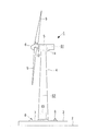
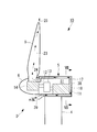
- FIG. 1 is a side view showing an example of a wind power generator to which cooling structures A to G in each embodiment described later can be applied.
- This wind power generator 1 includes a tower 4 erected on a reinforced concrete foundation 3 installed on the ground surface 2, a nacelle 5 installed at the upper end of the tower 4, and a substantially horizontal lateral rotation. And a rotor head 6 that is rotatably supported around the axis and is provided on the front end side of the nacelle 5.
- a so-called upwind type windmill in which the rotor head 6 is provided on the front end side of the nacelle 5 will be described.
- the present invention is also applicable to a downwind type windmill in which the rotor head 6 is provided on the rear end side of the nacelle 5. It will be apparent to those skilled in the art that this can be done.
- the tower 4 is a steel tube monopole type, and its cross-sectional shape is substantially circular.
- a base plate 7 made of, for example, a steel plate is fixed to the lower end portion of the tower 4, and the base plate 7 is fastened and fixed to the foundation 3 with a number of anchor bolts 8.
- a plurality of (for example, three) wind turbine blades 9 extending in the radial direction are attached to the rotor head 6, a generator 11 is accommodated in the nacelle 5, and the rotating shaft 12 of the rotor head 4 generates power. It is connected to the main shaft of the machine 11 through a speed increaser 13 (see FIG. 2). For this reason, the wind force of the external wind which hits the windmill blade 9 is converted into a rotational force that rotates the rotor head 6 and the rotating shaft 12, and the generator 11 is driven to generate power.
- the nacelle 5 can be swung in the horizontal direction at the upper end of the tower 4 together with the wind turbine blades 9, and is controlled by a driving device and a control device (not shown) so that the nacelle 5 is always directed efficiently in the windward direction.
- various heat generating devices such as a generator 11 and a main bearing (not shown) and a speed increaser 13 (see FIG. 2) are installed.
- a known hydraulic or electric pitch driving device 14 (see FIG. 2) is provided inside the rotor head 4 to adjust the pitch angle of the wind turbine blades 9 to an optimum angle corresponding to the air volume.
- the pitch driving device 14 is also a heat generating device that generates heat during its operation.
- various electric devices 15 are also installed in the internal space S ⁇ b> 2 of the tower 4. Examples of these electrical devices 15 include heat-generating devices such as converters and transformers.
- the heat generating devices installed in the internal spaces S1, S2 and the rotor head 4 by the cooling structures A to G in the embodiments described below.
- the heat of 11, 14, 15 is cooled.
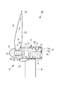
- FIG. 2 is a schematic longitudinal sectional view of the wind turbine generator 1A according to the first embodiment of the present invention.
- This wind power generator 1A includes a cooling structure A.
- the wall body 17 constituting the nacelle 5 has a double wall structure including an outer wall 17a and an inner wall 17b provided inside the outer wall 17a with a space therebetween, and the outer wall 17a.
- a space between the inner wall 17b and the inner wall 17b serves as a nacelle internal ventilation path 18. Outside air flows through the nacelle internal air passage 18 as cooling air.
- the wall body 17 has a double wall structure over the entire surface, but only a part of the wall body 17 may have a double structure.
- the nacelle internal air passage 18 is completely isolated from the internal space S 1 of the nacelle 5, and the generator 11 that is a heat generating device installed in the internal space S 1 is provided adjacent to the nacelle internal air passage 18. Yes. Specifically, the generator 11 is provided so as to be in close contact with the bottom surface and the rear surface of the inner wall 17 b constituting the nacelle internal ventilation path 18.
- the nacelle internal ventilation path 18 has an external air introduction port 21 for introducing external air blown from the front of the nacelle 5.
- the outside wind inlet 21 is provided so as to open toward the front, for example, at the front of the nacelle 5 directly below the rotor head 6 and in some cases on the left and right sides of the rotor head 6.
- the opening area of the outside wind introduction port 21 is set to be larger than the vertical cross-sectional area of the nacelle internal ventilation path 18, and the nacelle internal ventilation path 18 gradually becomes a passage from the outside wind introduction port 21 toward the downstream side in a side view. The area is narrow.
- a windmill internal air passage 23 is provided from the inside of the rotor head 4 to the inside of the windmill blade 9.
- the windmill internal air passage 23 communicates with the nacelle internal air passage 18 through a communication port 24 opened on the front surface of the nacelle 5.
- the pitch driving device 14 provided inside the rotor head 4 is sealed to the outside by a rotor hub, and its periphery is surrounded by a windmill internal air passage 23.
- An exhaust port 25 is provided near the tip of the wind turbine blade 9 to allow the wind turbine internal ventilation path 23 to communicate with the outside.
- the cooling structure A configured as described above operates as follows.
- the wind direction of the external wind is detected, and the nacelle 5 is automatically controlled so that the front surface thereof faces upwind.
- outside wind is introduced as cooling air from the outside wind introduction port 21 opened in the front surface of the nacelle 5 into the inside of the nacelle internal ventilation path 18 as indicated by an arrow.
- this cooling air circulates in the nacelle internal air passage 18, it cools the generator 11 which is a heat generating device provided in close contact with the inner wall 17b and the air in the internal space S1.
- the cooling air that has passed through the nacelle internal air passage 18 in this way flows through the communication port 24 to the wind turbine internal air passage 23 and passes around the pitch drive device 14 to cool the pitch drive device 14 that is also a heat generating device. Finally, the air passes through the inside of the wind turbine blade 9 and is discharged from the exhaust port 25 to the outside.
- this cooling structure A by a simple configuration in which the generator 11 is provided adjacent to the nacelle internal air passage 18 provided separately from the internal space S1 of the nacelle 5, the outside air flowing through the nacelle internal air passage 18 The generator 11 can be effectively cooled. And since the external air which flows through the nacelle internal ventilation path 18 is isolated and distribute
- the wall body 17 constituting the nacelle 5 has a double wall structure including an outer wall 17a and an inner wall 17b provided inside the outer wall 17a with a space therebetween, and a space between the outer wall 17a and the inner wall 17b. Since the nacelle internal air passage 18 is used, the surface area (heat transfer surface) of the nacelle internal air passage 18 can be increased to improve the cooling efficiency. When the distance between the outer wall 17a and the inner wall 17b is narrowed, the flow rate of the cooling air passing through the interior is increased and the cooling efficiency is increased. Therefore, even if the wall body 17 has a double wall structure, the wall body 17 is unlikely to be thick, and the nacelle 5 can be formed compactly. In addition, when the nacelle 5 is partially made into a double wall structure, it can be formed more compactly.
- a windmill internal air passage 23 is provided from the inside of the rotor head 6 to the inside of the windmill blade 9, and the windmill internal airway 23 is formed in a state where the pitch driving device 14 provided in the rotor head 6 is sealed from the outside. Since cooling is performed by the flowing cooling air, the pitch driving device 14 can be cooled while not being exposed to the outside air, and can be protected from corrosion, contamination, and the like.
- the passage area of the nacelle internal air passage 18 gradually becomes narrower as it goes downstream from the external air introduction port 21, the outside air taken into the nacelle internal air passage 18 from the external air introduction port 21 has a flow velocity at a stretch.
- the flow velocity of the entire cooling air flowing through the nacelle internal air passage 18 and the windmill internal air passage 23 can be increased.
- the negative pressure acts on the exhaust port 25 by the rotation of the wind turbine blade 9, the cooling air flowing through the nacelle internal ventilation path 18 and the wind turbine internal ventilation path 23 is sucked from the exhaust port 25, and also in this respect, the flow rate of the cooling air is increased. You can speed up. Then, by increasing the flow velocity of the cooling air in this way, the cooling efficiency of the heat generating devices such as the generator 11 and the pitch driving device 14 provided adjacent to the nacelle internal air passage 18 and the windmill internal air passage 23 is increased. Can do.
- an air blower such as a circulation fan 27 is installed in the internal space S1 of the nacelle 5 to circulate the air in the internal space S1, thereby preventing a local high temperature of the generator 11 or the like.
- the generated heat can be widely transmitted to the inner wall 17b to increase the heat exchange rate and improve the cooling performance.
- an air supply fan 28 or the like can be installed inside the nacelle internal ventilation path 18 to further increase the cooling air flow rate in the nacelle internal ventilation path 18 and the windmill internal ventilation path 23 to improve the cooling efficiency.
- FIG. 3 is a schematic longitudinal sectional view of a wind turbine generator 1B according to the second embodiment of the present invention.
- the wind power generator 1B includes a cooling structure B.
- This cooling structure B is different from the cooling structure A in the first embodiment described above in that the heat of the internal space S1 of the nacelle 5 is transferred to the inner wall 17b of the nacelle internal air passage 18 on the nacelle internal air passage 18 side.
- the heat transfer means for transferring the heat to the wind turbine and the heat transfer means for transferring the heat generated by the pitch driving device 14 to the wind turbine internal air passage 23 are provided. It is the same configuration.
- heat pipes 31 and 32 are used as the heat transfer means.
- the heat pipes 31 and 32 have a known structure in which, for example, a hydraulic fluid such as alternative chlorofluorocarbon is sealed inside a copper pipe.
- the heat pipe 31 installed in the internal space S1 of the nacelle 5 may be provided so as to come into contact with a heat generating device such as the generator 11. Further, the installation position of the heat pipe 31 may be provided not only in the vicinity of the heat generating device but also on the entire inner wall 17b constituting the nacelle internal ventilation path 18. Further, the heat pipe 32 provided in the pitch driving device 14 is disposed so as to penetrate the casing of the pitch driving device 14.
- the external wind introduced as cooling air from the external wind inlet 21 that opens to the front surface of the nacelle 5 is similar to the cooling structure A in the first embodiment, and the nacelle internal ventilation path 18 and the windmill internal ventilation.
- the heat generated by the heat generating devices such as the generator 11 and the pitch driving device 14 is cooled through the passage 23 and then discharged to the outside through the exhaust port 25.
- heat generated by the heat generating devices such as the generator 11 and the pitch driving device 14 is efficiently transferred to the nacelle internal air passage 18 and the wind turbine internal air passage 23 by the heat transfer action of the heat pipes 31 and 32. Heat can be actively dissipated to the cooling air side to cool the heat generating device more efficiently.
- FIG. 4 is a schematic longitudinal sectional view of a wind turbine generator 1C according to the third embodiment of the present invention.
- the wind power generator 1C includes a cooling structure C.
- This cooling structure C is different from the cooling structure A of the first embodiment only in that an uneven shape 35 is provided on the inner wall 17b constituting the nacelle internal ventilation path 18, and the other part is the cooling structure A. It is the same composition as.
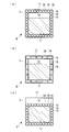
- the inner wall 17b is formed of a corrugated plate as shown in FIG. 5A, or a plurality of ribs 17c are formed on the outer surface of the inner wall 17b as shown in FIG. 5B. It is possible to project.
- the longitudinal direction of the groove of the concavo-convex shape 35 by the corrugated plate is along the width direction of the nacelle 5 (direction perpendicular to the paper surface). It is preferable to form the groove 35 having the concavo-convex shape 35 along the direction in which the outside wind introduced into the air 18 flows. Also, in the case of the rib 17c shown in FIG. 5B, it is preferable that the longitudinal direction of the rib 17c be aligned with the direction in which the outside air flows. Furthermore, the uneven shape 35 may be provided on the casing itself of the heat generating device such as the generator 11 or the pitch driving device 14.
- the surface area of the inner and outer surfaces of the inner wall 17b is increased, and the heat generated from the heating device such as the generator 11 is increased.
- the internal wall 17b efficiently receives the temperature in the internal space S1 that rises due to this heat, and dissipates this heat to the cooling air flowing through the nacelle internal air passage 18, thereby improving the cooling efficiency of the internal space S1. Can do.
- the cooling air used for cooling is discharged to the outside from the exhaust port 25 through the wind turbine internal ventilation path 23.
- FIG. 6 is a schematic longitudinal sectional view of a wind turbine generator 1D according to the fourth embodiment of the present invention
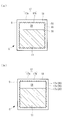
- FIGS. 7A to 7C are longitudinal sectional views taken along line VII-VII in FIG. is there.
- the wind power generator 1D includes a cooling structure D.
- this cooling structure D the difference from the cooling structure A of the first embodiment is that the wall body 17 constituting the nacelle 5 does not have a double wall structure, and a plurality of cylindrical shapes are formed inside the nacelle 5.
- the outside air passages 38 are arranged in a cage shape, for example, and the inside of these outside air passages 38 is the nacelle inner air passage 18.
- the outside air passage 38 is disposed so as to extend in the front-rear direction on the upper, lower, left, and right surfaces of the wall body 17 of the nacelle 5, and is disposed so as to extend in the up-down direction on the rear surface of the wall body 17.
- the arrangement direction is not limited.
- the intervals of the outdoor air passages 38 are arranged closely, they may be arranged with appropriate intervals.
- path 38 is just under the rotor head 6 of the front surface of the nacelle 5, or the rotor head 6 like the position of the external wind inlet 21 in the cooling structure A of 1st Embodiment. It is provided so as to open forward at a position on the left-right side.
- each nacelle internal air passage 18 communicates with the wind turbine internal air passage 23 formed from the inside of the rotor head 6 to the inside of the wind turbine blade 9 through the communication port 24. is doing.
- each outside air passage 38 is set larger than the vertical cross-sectional area of the intermediate portion of the outside air passage 38, and the passage area gradually narrows as it goes downstream from the opening 39. If it is configured in the funnel shape, the cooling efficiency can be improved by accelerating the flow velocity of the cooling air flowing through the outside air passage 38 (the nacelle internal air passage 18).
- the openings 39 of the respective external air circulation passages 38 may be integrated into one, and the plural external air circulation passages 38 may be branched from here to the downstream side.
- this cooling structure D a part of the external air blown to the front surface of the nacelle 5 flows into the nacelle internal ventilation path 18 from the opening 39 of each external air circulation passage 38 and passes around the internal space S1 of the nacelle 5.
- the heat generating device such as the generator 11 adjacent to the nacelle internal air passage 18 is cooled, and then flows into the wind turbine internal air passage 23 through the communication port 24 to cool the pitch driving device 14. It is discharged to the outside from the exhaust port 25 at the tip.
- the nacelle internal air passage 18 is disposed in the nacelle 5 relatively easily, and in some cases, the windmill internal air passage 23 is also provided, so that the generator 11 and the pitch driving device 14 are provided.
- the heat of the heat generating device such as can be cooled.
- the entire inner space S1 of the nacelle 5 and the heat generating devices such as the pitch driving device 14 are sealed from the outside, and the devices such as the generator 11 and the pitch driving device 14 are protected from corrosion, fouling, and the like. Can do.
- the nacelle internal ventilation path 18 can be added relatively easily later to an existing wind power generation apparatus that does not include the nacelle internal ventilation path 18.
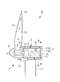
- FIG. 8 is a schematic longitudinal sectional view of a wind turbine generator 1E according to the fifth embodiment of the present invention.
- the wind power generator 1E includes a cooling structure E.
- the wall body 41 constituting the tower 4 has a double wall structure including an outer wall 41a and an inner wall 41b provided inside the outer wall 41a with a space therebetween.
- the inside of the inner wall 41b is an inner space S2
- the space between the outer wall 41a and the inner wall 41b is a tower internal air passage 42.
- the tower internal air passage 42 is isolated from the internal space S2, and an exothermic electrical device such as the converter 15a and the transformer 15b installed in the internal space S2 is adjacent to the tower internal air passage 42 (inner wall 41b). is doing.
- the wall body 41 has a double wall structure entirely, but only a part of the wall body 41 has a double structure, and a tower internal air passage 42 is partially provided, to which a converter 15a and a transformer 15b are provided. It may be adjacent.
- a nacelle internal air passage 18 similar to the cooling structures A and B of the first and second embodiments is formed inside the nacelle 5.
- the nacelle internal air passage 18 is not provided with the external air inlet 21 as in the cooling structures A and B, and the nacelle internal air passage 18 communicates with the tower internal air passage 42 via the communication portion 44.
- the configuration in which the nacelle internal air passage 18 communicates with the windmill internal air passage 23 via the communication port 24 is the same as that of the cooling structures A and B.
- the cooling structure E configured as described above operates as follows.
- the outside wind is introduced as cooling air from the outside wind inlet 43 into the tower internal air passage 42 as shown by the arrow, and flows through the tower internal air passage 42.
- the air in the exothermic converter 15a, the transformer 15b, and the internal space S2 that is in close contact with the inner wall 41b and is adjacent to the tower internal air passage 42 is cooled.
- the cooling air rises in the tower internal air passage 42 and flows into the nacelle internal air passage 18 through the communication portion 44.
- the cooling air is provided in close contact with the inner wall 17b of the nacelle 5.
- the generator 11 which is the generated heat generating device is cooled, then flows through the communication port 24 to the wind turbine internal ventilation path 23 to cool the pitch driving device 14, and finally passes through the wind turbine blade 9 and from the exhaust port 25. It is discharged outside.
- a circulation fan 47 is installed in the tower internal air passage 42, and the cooling air flowing in the tower internal air passage 42 is positively sent to the nacelle internal air passage 18, By cooperating with the air supply fan 28 provided, the amount of cooling air can be increased and the cooling performance can be improved.
- this cooling structure E not only the heat generating device (generator 11) provided in the nacelle 5 but also the heat generating devices (converter 15a, transformer 15b) provided in the tower 4 can be effectively cooled.
- the internal space S2 of the tower 4 can be sealed, it is possible to protect the internal equipment of the tower including the converter 15a and the transformer 15b from being exposed to the outside air, thereby protecting them from corrosion, contamination, and the like. .
- FIG. 9 is a schematic longitudinal sectional view of a wind turbine blade 9 according to a sixth embodiment of the present invention.
- the wind turbine blade 9 can be applied to the wind power generators 1A to 1E of the first to fifth embodiments, and includes a cooling structure F.
- this cooling structure F the exhaust port of the wind turbine internal air passage 23 formed inside the wind turbine blade 9 is formed on the leeward side of the wind turbine blade 9 with respect to the wind direction. That is, for example, the exhaust port 25a is provided at the rear edge position of the wind turbine blade 9, or the exhaust port 25b is provided at the side surface position. In short, it is preferable to provide the exhaust ports 25a and 25b at a place where negative pressure is applied by the wind hitting the wind turbine blades 9.
- this cooling structure F since a high negative pressure acts on the exhaust ports 25a and 25b of the windmill internal ventilation path 23, the cooling air flowing through the nacelle internal ventilation path 18, the windmill internal ventilation path 23, the tower internal ventilation path 42, and the like.
- the flow rate can be increased and the flow rate can be increased to increase the cooling efficiency.
- FIG. 10 is a schematic longitudinal sectional view of a wind turbine blade 9 according to a seventh embodiment of the present invention.
- the wind turbine blade 9 can be applied to the wind power generators 1A to 1E of the first to fifth embodiments, and includes a cooling structure G.
- an exhaust port 25 c of the wind turbine internal air passage 23 formed inside the wind turbine blade 9 is formed near the root of the wind turbine blade 9.
- the exhaust port 25c is formed in a range of about 0.5 m at the farthest from the root of the wind turbine blade 9.
- the exhaust port 25c is preferably formed on the leeward side with respect to the wind direction. Further, instead of providing the exhaust port 25 c at the rear edge position of the wind turbine blade 9, the exhaust port 25 d may be provided at the side surface position of the wind turbine blade 9.
- cooling structure G it is possible to shorten the overall length of the wind turbine internal air passage 23 inside the wind turbine blade 9 to avoid pressure loss, and to increase the cooling air flow velocity and flow rate to increase the cooling efficiency.
- the present invention is not limited to the above-described aspects of the first to seventh embodiments.
- Wind power generator 4 Tower 5 Nacelle 6 Rotor head 9 Windmill blade 11 Generator (heat generating device inside nacelle) 14 Pitch drive device (heat generating device inside the rotor head) 15a Converter (heating equipment inside the tower) 15b Transformer (heating equipment inside the tower) 17 Wall body 17a Outer wall 17b Inner wall 18 Nacelle internal air passage 21 External wind introduction port 23 Windmill internal air passage 25 Exhaust port 31, 32 Heat pipe (heat transfer means) 35 Concave and convex shape 38 Outside air passage 42 Tower internal air passages A to G Cooling structure S1 Nacelle internal space S2 Tower internal space
Landscapes
- Engineering & Computer Science (AREA)
- Physics & Mathematics (AREA)
- Thermal Sciences (AREA)
- Life Sciences & Earth Sciences (AREA)
- Sustainable Development (AREA)
- Sustainable Energy (AREA)
- Chemical & Material Sciences (AREA)
- Combustion & Propulsion (AREA)
- Mechanical Engineering (AREA)
- General Engineering & Computer Science (AREA)
- Wind Motors (AREA)
Abstract
風力発電装置(1A)は、風車翼(9)に外風を受けて回転するロータヘッド(6)が、ナセル(5)の内部に設置された発電機(11)を駆動して発電する風力発電装置(1A)において、ナセル(5)の内部に、外気が冷却空気として流通するナセル内部通気路(18)を設け、このナセル内部通気路(18)をナセル(5)の内部空間(S1)に対して隔離するとともに、この内部空間(S1)に設置される発熱機器(例えば発電機(11))を、ナセル内部通気路(18)に隣接させて設けたことを特徴とする。具体的には、ナセル(5)を構成する壁体(17)の少なくとも一部を、外壁(17a)と内壁(17b)とを備えた二重壁構造とし、外壁(17a)と内壁(17b)との間の空間をナセル内部通気路(18)とし、内壁(17b)に発熱機器を隣接させて設けた。
Description
本発明は、運転時における機器の発熱を、外気の導入により冷却するようにした風力発電装置に関するものである。
標準的な風力発電装置は、風車翼を備えたロータヘッドが風力を受けて回転し、この回転を増速機により増速する等して発電機を駆動し、発電を行う装置である。ロータヘッドは、地面等に立設されたタワーの上に設置されてヨー旋回可能なナセルの端部に取り付けられ、略水平な横方向の回転軸線周りに回転可能となるように支持されている。
ナセルの内部には発電機を始めとする発熱機器が設置され、タワーの内部にもコンバータや変圧器といった発熱機器が設置される場合があり、安定した運転を継続するためには、これらの電気機器を適切に冷却する必要がある。
従来の単純な冷却構造としては、例えば特許文献1に開示されているように、ナセルの内部に換気ファンを設置し、外部の冷たい空気をナセル内部に強制的に導入して発熱機器の冷却を行うようにした風力発電装置がある。
また、例えば特許文献2に開示されているように、ナセルの内部に設置された発熱機器をカプセル状に被包し、ファンで上記カプセル内に冷却空気を通気する閉ループ通気路を構成し、この閉ループ通気路の途中に冷却器を介在させ、この冷却器を風車翼の風下側に設置することによって、外風により冷却器を空冷し、冷却器の内部を流れる冷却空気を熱交換させるようにした風力発電装置がある。
また、例えば特許文献2に開示されているように、ナセルの内部に設置された発熱機器をカプセル状に被包し、ファンで上記カプセル内に冷却空気を通気する閉ループ通気路を構成し、この閉ループ通気路の途中に冷却器を介在させ、この冷却器を風車翼の風下側に設置することによって、外風により冷却器を空冷し、冷却器の内部を流れる冷却空気を熱交換させるようにした風力発電装置がある。
しかしながら、特許文献1の風力発電装置の構成では、外気が換気ファンによってナセル内部に導入されるため、外気に含まれる水分や塩分、塵埃等の異物によってナセル内部の構造物や機器類の腐食、汚損等が生じやすく、機械的、電気的に好ましくなかった。これを改善するには、ナセルの外気導入口に異物除去用のフィルタを設ける必要があるが、フィルタの設置によって圧力損失が発生し、充分な量の外風を取り入れることができなくなってしまう。
また、特許文献2の風力発電装置の構成では、発熱機器がカプセル状に被包されているため、発熱機器が外気に触れないという点では好ましいが、ナセル内部の構造が複雑になることと、空冷式の冷却器がどうしても大型になるためにナセル全体が大型化してしまうという難点がある。その上、常に外気に晒される冷却器の腐食対策を充分に行わなければならず、これらの要因によって風力発電装置の建造コストが高額になるという問題があった。
本発明は、上記の事情に鑑みてなされたものであり、簡素でコンパクト、かつ安価な構成により、ナセルやタワーの内部に設置された発熱機器を良好に冷却するとともに、これらの機器類を腐食、汚損等から保護することのできる風力発電装置を提供することを目的とする。
本発明は、上記の課題を解決するため、下記の手段を採用した。
即ち、本発明に係る風力発電装置は、風車翼に外風を受けて回転するロータヘッドが、ナセルの内部に設置された発電機を駆動して発電する風力発電装置において、前記ナセルの内部に、外気が前記ナセルの内部空間に対して隔離されて流通するナセル内部通気路が設けられる。
即ち、本発明に係る風力発電装置は、風車翼に外風を受けて回転するロータヘッドが、ナセルの内部に設置された発電機を駆動して発電する風力発電装置において、前記ナセルの内部に、外気が前記ナセルの内部空間に対して隔離されて流通するナセル内部通気路が設けられる。
このような風力発電装置によれば、ナセル内部通気路を流通する外気によって、ナセルの内部空間、ひいてはナセル内部に設置されている発熱機器等を冷却することができる。しかも、これによってナセルの内部空間を密閉することができるため、発熱機器を始めとするナセル内部機器を外気に触れさせないようにして、腐食、汚損等から保護することができる。
また、本発明の第1の態様に係る風力発電装置は、前記ナセル内部通気路が、その上流側よりも下流側の方が通路面積が狭くなるように形成されている。これにより、ナセル内部通気路内を流れる冷却空気の流速を加速させて冷却効率を高めることができる。
さらに、本発明の第2の態様に係る風力発電装置は、前記ナセルを構成する壁体の少なくとも一部を、外壁と、この外壁の内側に間隔を介して設けられた内壁とを備えた二重壁構造とし、前記外壁と前記内壁との間の空間を前記ナセル内部通気路とした。
上記構成によれば、ナセル内部通気路の表面積を大きくできるため、冷却効率を向上させることができる。また、外壁と内壁との間隔は狭くした方が内部を通る冷却空気の流速が速まって冷却効率が高くなる。したがって、ナセルを構成する壁体を二重壁構造としても、壁体が厚くなりにくく、ナセルをコンパクトに形成することができる。
上記構成によれば、ナセル内部通気路の表面積を大きくできるため、冷却効率を向上させることができる。また、外壁と内壁との間隔は狭くした方が内部を通る冷却空気の流速が速まって冷却効率が高くなる。したがって、ナセルを構成する壁体を二重壁構造としても、壁体が厚くなりにくく、ナセルをコンパクトに形成することができる。
そして、本発明の第3の態様に係る風力発電装置は、前記ナセルの内部に少なくとも1本の筒状の外気流通通路を配設し、この外気流通通路の内部を前記ナセル内部通気路とした。こうすれば、比較的容易にナセルの内部にナセル内部通気路を配設することができる。また、既存の風力発電装置に後からナセル内部通気路を追加設置することもできる。
また、本発明の第4の態様に係る風力発電装置は、前記ナセルの内部空間に設置される発熱機器を、前記ナセル内部通気路に隣接させて設けた。こうすれば、簡素な構成により、ナセル内部通気路を流れる外気によって発熱機器を効果的に冷却することができる。
さらに、本発明の第5の態様に係る風力発電装置は、前記ナセルの内部空間の熱を、前記ナセル内部通気路側に熱移送する熱移送手段を設けた。これにより、ナセル内部に設置された発熱機器の熱をナセル内部通気路側に積極的に移送し、より効率良く発熱機器を冷却することができる。
そして、本発明の第6の態様に係る風力発電装置は、前記ナセル内部通気路に凹凸形状を設けた。これにより、ナセル内部通気路の表面積を大きくして冷却効率を向上させることができる。凹凸形状としては、ナセル内部通気路を構成する壁を波板状にしたり、この壁にフィンを突設したりすることが考えられる。
また、本発明の第7の態様に係る風力発電装置は、前記ナセル内部通気路を通過した冷却空気を、前記ロータヘッドの内部に設置された発熱機器の周囲を通過させて最終的に前記風車翼の内部を通して外部に排出させる風車内部通気路を設けた。
上記構成によれば、風車翼が回転することによって発生する負圧により、ナセル内部通気路および風車内部通気路を流れる冷却空気が吸引されて外部に排出されるため、冷却空気の流速を速めて冷却効率を向上させることができる。しかも、ロータヘッド内部に配設された発熱機器を密封構造としながら冷却することができ、この発熱機器を外気に触れさせないようにして、腐食、汚損等から保護することができる。
また、本発明の第8の態様に係る風力発電装置は、前記風車内部通気路の外部への排気口を、前記風車翼の、風向きに対して風下側に形成した。こうすることにより、排気口に高い負圧が作用するため、ナセル内部通気路、風車内部通気路、タワー内部通気路等を流れる冷却空気の流速を速めるとともに流量を増大させ、冷却効率を高めることができる。
さらに、本発明の第9の態様に係る風力発電装置は、前記排気口を、前記風車翼の根本付近に形成した。これにより、風車翼の内部における風車内部通気路の全長を短くして圧力損失を回避し、冷却空気の流速および流量を大きくして、冷却効率を高めることができる。
そして、本発明の第10の態様に係る風力発電装置は、前記ナセルが上端部に設置されるタワーの内部に、外気が冷却空気として流通するタワー内部通気路を設け、このタワー内部通気路を前記タワーの内部空間に対して隔離するとともに、前記タワーの内部空間に設置される発熱機器を、前記タワー内部通気路に隣接させて設け、このタワー内部通気路を前記ナセル内部通気路に連通させた。
上記構成によれば、タワー内部に配設された発熱機器を効果的に冷却できる上に、タワーの内部空間を密閉することができるため、発熱機器を始めとするタワー内部機器を外気に触れさせないようにして、腐食、汚損等から保護することができる。
以上のように、本発明に係る風力発電装置によれば、簡素でコンパクト、かつ安価な構成により、ナセルやタワーの内部に設置された発熱機器を良好に冷却するとともに、これらの機器類および他の内部構造物を腐食、汚損等から保護することができる。
以下、本発明に係る風力発電装置の実施形態について図面に基づいて説明する。
図1は、後に説明する各実施形態における冷却構造A~Gを適用可能な風力発電装置の一例を示す側面図である。この風力発電装置1は、地表面2に設置された鉄筋コンクリート製の基礎3上に立設されるタワー4と、このタワー4の上端部に設置されるナセル5と、略水平な横方向の回転軸線周りに回転可能に支持されてナセル5の前端部側に設けられるロータヘッド6とを有している。本例では、ロータヘッド6がナセル5の前端部側に設けられる所謂アップウィンド型の風車について説明するが、ロータヘッド6がナセル5の後端部側に設けられるダウンウィンド型の風車にも適用できることは、当業者には明らかであろう。
図1は、後に説明する各実施形態における冷却構造A~Gを適用可能な風力発電装置の一例を示す側面図である。この風力発電装置1は、地表面2に設置された鉄筋コンクリート製の基礎3上に立設されるタワー4と、このタワー4の上端部に設置されるナセル5と、略水平な横方向の回転軸線周りに回転可能に支持されてナセル5の前端部側に設けられるロータヘッド6とを有している。本例では、ロータヘッド6がナセル5の前端部側に設けられる所謂アップウィンド型の風車について説明するが、ロータヘッド6がナセル5の後端部側に設けられるダウンウィンド型の風車にも適用できることは、当業者には明らかであろう。
タワー4は、鋼管製のモノポール式であり、その横断面形状が略円形である。タワー4の下端部には例えば鋼板製のベースプレート7が固定され、このベースプレート7が多数のアンカーボルト8で基礎3に締結固定されている。ロータヘッド6には、放射方向に延びる複数枚(例えば3枚)の風車翼9が取り付けられており、ナセル5の内部には発電機11が収容設置され、ロータヘッド4の回転軸12が発電機11の主軸に増速機13(図2参照)を介して連結されている。このため、風車翼9に当たった外風の風力が、ロータヘッド6と回転軸12を回転させる回転力に変換され、発電機11が駆動されて発電が行われる。
ナセル5は、風車翼9と共に、タワー4の上端において水平方向に旋回することができ、図示しない駆動装置と制御装置により、常に風上方向に指向して効率良く発電できるように制御される。ナセル5の内部空間S1内には、発電機11を始めとし、図示しない主軸受や増速機13(図2参照)等、各種の発熱機器が設置されている。また、ロータヘッド4の内部には、風車翼9のピッチ角を風量に見合う最適な角度に調整するための、油圧や電動の公知のピッチ駆動装置14(図2参照)が設けられている。このピッチ駆動装置14も、その作動時に発熱する発熱機器である。さらに、タワー4の内部空間S2内にも各種の電気機器15が設置されている。これらの電気機器15としては、コンバータや変圧器といった発熱性のあるものが例示される。
ナセル5の内部空間S1およびタワー4の内部空間S2は密室状であるため、以下に述べる各実施形態における冷却構造A~Gにより、内部空間S1,S2およびロータヘッド4内に設置された発熱機器11,14,15の熱を冷却するようになっている。
(第1実施形態)
図2は、本発明の第1実施形態に係る風力発電装置1Aの概略的な縦断面図である。この風力発電装置1Aは冷却構造Aを備えている。この冷却構造Aにおいて、ナセル5を構成する壁体17は、外壁17aと、この外壁17aの内側に間隔を介して設けられた内壁17bとを備えた二重壁構造となっており、外壁17aと内壁17bとの間の空間がナセル内部通気路18となっている。このナセル内部通気路18には外気が冷却空気として流通する。なお、ここでは壁体17が全面的に二重壁構造となっているが、一部だけを二重構造にしてもよい。
図2は、本発明の第1実施形態に係る風力発電装置1Aの概略的な縦断面図である。この風力発電装置1Aは冷却構造Aを備えている。この冷却構造Aにおいて、ナセル5を構成する壁体17は、外壁17aと、この外壁17aの内側に間隔を介して設けられた内壁17bとを備えた二重壁構造となっており、外壁17aと内壁17bとの間の空間がナセル内部通気路18となっている。このナセル内部通気路18には外気が冷却空気として流通する。なお、ここでは壁体17が全面的に二重壁構造となっているが、一部だけを二重構造にしてもよい。
ナセル内部通気路18は、ナセル5の内部空間S1に対して完全に隔離されており、内部空間S1に設置される発熱機器である発電機11がナセル内部通気路18に隣接させて設けられている。具体的には、発電機11が、ナセル内部通気路18を構成している内壁17bの底面と後面に密着するように設けられている。
ナセル内部通気路18は、ナセル5の前方から吹き付ける外風を導入する外風導入口21を有している。この外風導入口21は、例えばナセル5の前面の、ロータヘッド6の直下と、場合によってはロータヘッド6の左右側方の位置において、前方に向かって開くように設けられている。この外風導入口21の開口面積は、ナセル内部通気路18の縦断面積よりも大きく設定されており、側面視でナセル内部通気路18は外風導入口21から下流側に進むにしたがって次第に通路面積が狭くなっている。
一方、ロータヘッド4の内部から風車翼9の内部にかけて風車内部通気路23が設けられている。この風車内部通気路23は、ナセル5の前面に開設された連通口24を介してナセル内部通気路18に連通している。ロータヘッド4の内部に設けられたピッチ駆動装置14はロータハブによって外部に対し密封されており、その周囲が風車内部通気路23に囲まれている。そして、風車翼9の先端付近に、風車内部通気路23を外部に連通させる排気口25が設けられている。
以上のように構成された冷却構造Aは、次のように作用する。
風力発電装置1Aに外風が吹き付けた場合、この外風の風向が検知されてナセル5がその前面を風上に向けるように自動制御される。このため、ナセル5の前面に開口している外風導入口21からナセル内部通気路18の内部に矢印で示すように外風が冷却空気として導入される。この冷却空気はナセル内部通気路18内を流通する際に、内壁17bに密着して設けられた発熱機器である発電機11と、内部空間S1の空気を冷却する。このようにナセル内部通気路18内を通過した冷却空気は、連通口24を経て風車内部通気路23に流れ、ピッチ駆動装置14の周囲を通過して同じく発熱機器であるピッチ駆動装置14を冷却し、最終的に風車翼9の内部を通って排気口25から外部に排出される。
風力発電装置1Aに外風が吹き付けた場合、この外風の風向が検知されてナセル5がその前面を風上に向けるように自動制御される。このため、ナセル5の前面に開口している外風導入口21からナセル内部通気路18の内部に矢印で示すように外風が冷却空気として導入される。この冷却空気はナセル内部通気路18内を流通する際に、内壁17bに密着して設けられた発熱機器である発電機11と、内部空間S1の空気を冷却する。このようにナセル内部通気路18内を通過した冷却空気は、連通口24を経て風車内部通気路23に流れ、ピッチ駆動装置14の周囲を通過して同じく発熱機器であるピッチ駆動装置14を冷却し、最終的に風車翼9の内部を通って排気口25から外部に排出される。
この冷却構造Aによれば、ナセル5の内部空間S1に対し隔離させて設けたナセル内部通気路18に発電機11を隣接させて設けるという簡素な構成により、ナセル内部通気路18を流れる外気によって発電機11を効果的に冷却することができる。しかも、ナセル内部通気路18を流れる外気がナセル5の内部空間S1に対し隔離されて流通するため、ナセル5の内部空間S1を密閉空間とすることができる。このため、発電機11を始めとするナセル5の内部機器を外気に触れさせないようにして、腐食、汚損等から確実に保護することができる。
また、ナセル5を構成する壁体17を、外壁17aと、この外壁17aの内側に間隔を介して設けられた内壁17bとからなる二重壁構造とし、外壁17aと内壁17bとの間の空間をナセル内部通気路18としたため、ナセル内部通気路18の表面積(伝熱面)を大きくして冷却効率を向上させることができる。外壁17aと内壁17bとの間隔は、狭くした方が内部を通る冷却空気の流速が速まって冷却効率が高くなる。したがって、壁体17を二重壁構造としても、壁体17が厚くなりにくく、ナセル5をコンパクトに形成することができる。なお、ナセル5を部分的に二重壁構造にした場合には、よりコンパクトに形成することができる。
さらに、ロータヘッド6の内部から風車翼9の内部にかけて風車内部通気路23を設け、ロータヘッド6の内部に設けられたピッチ駆動装置14を外部に対して密封した状態で風車内部通気路23を流れる冷却空気によって冷却するようにしたため、ピッチ駆動装置14を外気に触れさせないようにしながら冷却し、腐食、汚損等から保護することができる。
ナセル内部通気路18は、外風導入口21から下流側に進むにしたがって次第に通路面積が狭くなっているため、外風導入口21からナセル内部通気路18内に取り込まれた外気は一気に流速が加速し、これによってナセル内部通気路18および風車内部通気路23を流れる冷却空気全体の流速を速めることができる。また、風車翼9の回転によって排気口25に負圧が作用するため、ナセル内部通気路18および風車内部通気路23を流れる冷却空気が排気口25から吸引され、この点でも冷却空気の流速を速めることができる。そして、このように冷却空気の流速を速めることにより、ナセル内部通気路18および風車内部通気路23に隣接して設けられた発電機11やピッチ駆動装置14等の発熱機器の冷却効率を高めることができる。
なお、場合によっては、ナセル5の内部空間S1内に循環ファン27等の送風機器を設置し、内部空間S1内の空気を循環させることにより、発電機11等の局部的な高温化を防止するとともに、生じた熱を内壁17bに広く伝達して熱交換率を高め、冷却性能を向上させることができる。同じく、ナセル内部通気路18の内部に送気ファン28等を設置し、ナセル内部通気路18および風車内部通気路23内における冷却空気の流速を一段と高めて冷却効率を向上させることもできる。
(第2実施形態)
図3は、本発明の第2実施形態に係る風力発電装置1Bの概略的な縦断面図である。この風力発電装置1Bは冷却構造Bを備えている。この冷却構造Bにおいて、前述の第1実施形態における冷却構造Aと異なる点は、ナセル内部通気路18を構成している内壁17bに、ナセル5の内部空間S1の熱をナセル内部通気路18側に熱移送する熱移送手段が設けられている点と、ピッチ駆動装置14の発する熱を風車内部通気路23側に熱移送する熱移送手段が設けられている点のみであり、他の部分は同一の構成である。上記の熱移送手段としては、例えばヒートパイプ31,32が用いられている。
図3は、本発明の第2実施形態に係る風力発電装置1Bの概略的な縦断面図である。この風力発電装置1Bは冷却構造Bを備えている。この冷却構造Bにおいて、前述の第1実施形態における冷却構造Aと異なる点は、ナセル内部通気路18を構成している内壁17bに、ナセル5の内部空間S1の熱をナセル内部通気路18側に熱移送する熱移送手段が設けられている点と、ピッチ駆動装置14の発する熱を風車内部通気路23側に熱移送する熱移送手段が設けられている点のみであり、他の部分は同一の構成である。上記の熱移送手段としては、例えばヒートパイプ31,32が用いられている。
ヒートパイプ31,32は、例えば銅のパイプの内部に代替フロン等の作動液が封入された公知の構造のものである。ナセル5の内部空間S1に設置されているヒートパイプ31は、発電機11等の発熱機器に接触するように設けてもよい。また、このヒートパイプ31の設置位置は、発熱機器の近傍のみならず、ナセル内部通気路18を構成する内壁17bに全面的に設けてもよい。また、ピッチ駆動装置14に設けられているヒートパイプ32は、ピッチ駆動装置14のケーシングを貫通するように配設されている。
この冷却構造Bにおいて、ナセル5の前面に開口する外風導入口21から冷却空気として導入された外風は、第1実施形態における冷却構造Aと同様に、ナセル内部通気路18と風車内部通気路23を通って、発電機11やピッチ駆動装置14等の発熱機器が発する熱を冷却した後、排気口25から外部に排出される。その際、ヒートパイプ31,32の熱移送作用により、発電機11やピッチ駆動装置14等の発熱機器が発する熱がナセル内部通気路18および風車内部通気路23側に効率良く移送されるため、熱を積極的に冷却空気側に放熱させて、より効率良く発熱機器を冷却することができる。
(第3実施形態)
図4は、本発明の第3実施形態に係る風力発電装置1Cの概略的な縦断面図である。この風力発電装置1Cは冷却構造Cを備えている。この冷却構造Cにおいて、第1実施形態の冷却構造Aと異なる点は、ナセル内部通気路18を構成する内壁17bに凹凸形状35が設けられている点のみであり、他の部分は冷却構造Aと同様な構成である。凹凸形状35の形成例としては、図5(a)にも示すように、内壁17bを波板で形成したり、図5(b)に示すように、内壁17bの外面に複数のリブ17cを突設したりすることが考えられる。
図4は、本発明の第3実施形態に係る風力発電装置1Cの概略的な縦断面図である。この風力発電装置1Cは冷却構造Cを備えている。この冷却構造Cにおいて、第1実施形態の冷却構造Aと異なる点は、ナセル内部通気路18を構成する内壁17bに凹凸形状35が設けられている点のみであり、他の部分は冷却構造Aと同様な構成である。凹凸形状35の形成例としては、図5(a)にも示すように、内壁17bを波板で形成したり、図5(b)に示すように、内壁17bの外面に複数のリブ17cを突設したりすることが考えられる。
なお、図4では波板による凹凸形状35の溝の長手方向がナセル5の幅方向(紙面に対して垂直な方向)に沿っているが、実際には外風導入口21からナセル内部通気路18内に取り入れられた外風の流れる方向に沿って凹凸形状35の溝を形成するのが好ましい。また、図5(b)に示すリブ17cの場合も、リブ17cの長手方向を外風の流れる方向に沿わせた方がよい。さらに、発電機11やピッチ駆動装置14等の発熱機器のケーシング自体に凹凸形状35を設けてもよい。
この冷却構造Cのように、ナセル内部通気路18を構成する内壁17bに凹凸形状35が設けることにより、内壁17bの内外面の表面積を大きくして、発電機11等の発熱機器から発せられる熱、およびこの熱によって上昇する内部空間S1内の温度を内壁17bに効率良く受熱させ、この熱を、ナセル内部通気路18を流れる冷却空気に放熱させて、内部空間S1の冷却効率を向上させることができる。もちろん、発熱機器11,14等のケーシング自体に凹凸形状を設ければ、より効果的に放熱させることができる。冷却に供された冷却空気は、風車内部通気路23を経て排気口25から外部に排出される。
(第4実施形態)
図6は、本発明の第4実施形態に係る風力発電装置1Dの概略的な縦断面図であり、図7(a)~(c)は図6のVII-VII線に沿う縦断面図である。この風力発電装置1Dは冷却構造Dを備えている。この冷却構造Dにおいて、第1実施形態の冷却構造Aと異なる点は、ナセル5を構成する壁体17が二重壁構造になっていない点と、このナセル5の内部に複数の筒状の外気流通通路38が例えばケージ状に配設され、これらの外気流通通路38の内部がナセル内部通気路18とされている点である。
図6は、本発明の第4実施形態に係る風力発電装置1Dの概略的な縦断面図であり、図7(a)~(c)は図6のVII-VII線に沿う縦断面図である。この風力発電装置1Dは冷却構造Dを備えている。この冷却構造Dにおいて、第1実施形態の冷却構造Aと異なる点は、ナセル5を構成する壁体17が二重壁構造になっていない点と、このナセル5の内部に複数の筒状の外気流通通路38が例えばケージ状に配設され、これらの外気流通通路38の内部がナセル内部通気路18とされている点である。
外気流通通路38は、例えばナセル5の壁体17の上下左右の面においては前後方向に延びるように配設され、壁体17の後面においては上下方向に延びるように配設されているが、この配設方向には限定されない。また、各外気流通通路38の間隔は密に並べられているが、適宜間隔を空けて配設してもよい。なお、各外気流通通路38の開口部39は、第1実施形態の冷却構造Aにおける外風導入口21の位置と同様に、ナセル5の前面の、ロータヘッド6の直下や、ロータヘッド6の左右側方の位置において、前方に向かって開くように設けられている。
そして、ナセル5の内部に設置された発電機11等の発熱機器が、外気流通通路38、即ちナセル内部通気路18に隣接するように配設されている。この実施形態では、発電機11の底面、左右側面、および後面にナセル内部通気路18が隣接している。各ナセル内部通気路18の末端部は、第1実施形態における冷却構造Aと同様に、ロータヘッド6の内部から風車翼9の内部にかけて形成された風車内部通気路23に連通口24を経て連通している。
なお、各外気流通通路38の開口部39の開口面積を、外気流通通路38の中間部の縦断面積よりも大きく設定し、開口部39から下流側に進むにしたがって次第に通路面積が狭くなるようなファンネル管状に構成すれば、外気流通通路38の内部(ナセル内部通気路18)を流れる冷却空気の流速を加速させて冷却効率の向上を図ることができる。また、各外気流通通路38の開口部39を一つにまとめて、ここから下流側に向かって複数の外気流通通路38が分岐するようにしてもよい。
この冷却構造Dにおいては、ナセル5の前面に吹き付ける外風の一部が、各外気流通通路38の開口部39からナセル内部通気路18に流入してナセル5の内部空間S1の周囲を通りながら、ナセル内部通気路18に隣接している発電機11等の発熱機器を冷却し、次に連通口24を経て風車内部通気路23に流入し、ピッチ駆動装置14を冷却した後に、風車翼9先端の排気口25から外部に排出される。
この冷却構造Dの構成によれば、比較的容易にナセル5の内部にナセル内部通気路18を配設し、場合によっては風車内部通気路23も併設して、発電機11やピッチ駆動装置14等の発熱機器の熱を冷却することができる。そして、ナセル5の内部空間S1全体とピッチ駆動装置14等の発熱機器を外部に対して密閉された構造とし、発電機11やピッチ駆動装置14等の機器類を腐食、汚損等から保護することができる。さらに、ナセル内部通気路18を備えていない既存の風力発電装置に後からナセル内部通気路18を比較的容易に追加設置することもできる。
なお、図7(b)に示すように、外気流通通路38のパイプ断面形状を角型や扁平型にすることにより、発電機11等の発熱機器やナセル5の壁体17に対して広い面積で外気流通通路38を接触させ、冷却効率を高めることができる。また、場合によっては図7(c)に示すように、発電機11等の発熱機器を被包するように外気流通通路38(ナセル内部通気路18)を設けて、より確実に発熱機器を冷却するようにしてもよい。
(第5実施形態)
図8は、本発明の第5実施形態に係る風力発電装置1Eの概略的な縦断面図である。この風力発電装置1Eは冷却構造Eを備えている。この風力発電装置1E(冷却構造E)において、タワー4を構成する壁体41は、外壁41aと、この外壁41aの内側に間隔を介して設けられた内壁41bとを備えた二重壁構造となっており、内壁41bの内側が内側空間S2とされ、外壁41aと内壁41bとの間の空間がタワー内部通気路42とされている。タワー内部通気路42は内部空間S2に対して隔離されており、内部空間S2に設置されているコンバータ15aや変圧器15bといった発熱性のある電気機器がタワー内部通気路42(内壁41b)に隣接している。なお、ここでは壁体41が全面的に二重壁構造となっているが、一部だけを二重構造にしてタワー内部通気路42を部分的に設け、これにコンバータ15a、変圧器15bを隣接させてもよい。
図8は、本発明の第5実施形態に係る風力発電装置1Eの概略的な縦断面図である。この風力発電装置1Eは冷却構造Eを備えている。この風力発電装置1E(冷却構造E)において、タワー4を構成する壁体41は、外壁41aと、この外壁41aの内側に間隔を介して設けられた内壁41bとを備えた二重壁構造となっており、内壁41bの内側が内側空間S2とされ、外壁41aと内壁41bとの間の空間がタワー内部通気路42とされている。タワー内部通気路42は内部空間S2に対して隔離されており、内部空間S2に設置されているコンバータ15aや変圧器15bといった発熱性のある電気機器がタワー内部通気路42(内壁41b)に隣接している。なお、ここでは壁体41が全面的に二重壁構造となっているが、一部だけを二重構造にしてタワー内部通気路42を部分的に設け、これにコンバータ15a、変圧器15bを隣接させてもよい。
そして、例えば地表面2に近い外壁41aの周面に1箇所、あるいは複数箇所の外風導入口43が設けられ、ここからタワー内部通気路42内に外気が冷却空気として導入されるようになっている。一方、ナセル5の内部には、先の実施形態1,2の冷却構造A,Bと同様なナセル内部通気路18が形成されている。しかし、このナセル内部通気路18には冷却構造A,Bのような外風導入口21が設けられておらず、ナセル内部通気路18は連通部44を介してタワー内部通気路42に連通している。なお、ナセル内部通気路18が連通口24を介して風車内部通気路23に連通している構成は冷却構造A,Bと同様である。
以上のように構成された冷却構造Eは、次のように作用する。
風力発電装置1Eに外風が吹き付けた場合、この外風が矢印で示すように外風導入口43からタワー内部通気路42内に冷却空気として導入され、タワー内部通気路42内を流通する際に、内壁41bに密着してタワー内部通気路42に隣接している発熱性のあるコンバータ15a、変圧器15b、および内部空間S2の空気を冷却する。その後、冷却空気はタワー内部通気路42内を上昇し、連通部44を経てナセル内部通気路18に流入し、以後は冷却構造A,Bと同様に、ナセル5の内壁17bに密着して設けられた発熱機器である発電機11を冷却し、次に連通口24を経て風車内部通気路23に流れてピッチ駆動装置14を冷却し、最後に風車翼9の内部を通って排気口25から外部に排出される。
風力発電装置1Eに外風が吹き付けた場合、この外風が矢印で示すように外風導入口43からタワー内部通気路42内に冷却空気として導入され、タワー内部通気路42内を流通する際に、内壁41bに密着してタワー内部通気路42に隣接している発熱性のあるコンバータ15a、変圧器15b、および内部空間S2の空気を冷却する。その後、冷却空気はタワー内部通気路42内を上昇し、連通部44を経てナセル内部通気路18に流入し、以後は冷却構造A,Bと同様に、ナセル5の内壁17bに密着して設けられた発熱機器である発電機11を冷却し、次に連通口24を経て風車内部通気路23に流れてピッチ駆動装置14を冷却し、最後に風車翼9の内部を通って排気口25から外部に排出される。
なお、場合によっては、タワー内部通気路42内に循環ファン47を設置し、タワー内部通気路42内を流れる冷却空気を積極的にナセル内部通気路18側に送り、ナセル内部通気路18内に設けられた送気ファン28と共働させて冷却空気量を増やし、冷却性能を向上させることができる。
この冷却構造Eによれば、ナセル5内に設けられた発熱機器(発電機11)のみならず、タワー4内に設けられた発熱機器(コンバータ15a、変圧器15b)も効果的に冷却することができ、しかもタワー4の内部空間S2を密閉することができるため、コンバータ15a、変圧器15bを始めとするタワー内部機器を外気に触れさせないようにして、腐食、汚損等から保護することができる。
(第6実施形態)
図9は、本発明の第6実施形態に係る風車翼9の概略的な縦断面図である。この風車翼9は、第1~第5実施形態の風力発電装置1A~1Eに適用することができ、冷却構造Fを備えている。この冷却構造Fでは、風車翼9の内部に形成された風車内部通気路23の排気口が、風車翼9の、風向きに対して風下側に形成されている。つまり、例えば風車翼9の後縁位置に排気口25aを設ける、あるいは側面位置に排気口25bを設ける。要するに、風車翼9に当たる風によって負圧が作用する場所に排気口25a,bを設けるのが好ましい。
図9は、本発明の第6実施形態に係る風車翼9の概略的な縦断面図である。この風車翼9は、第1~第5実施形態の風力発電装置1A~1Eに適用することができ、冷却構造Fを備えている。この冷却構造Fでは、風車翼9の内部に形成された風車内部通気路23の排気口が、風車翼9の、風向きに対して風下側に形成されている。つまり、例えば風車翼9の後縁位置に排気口25aを設ける、あるいは側面位置に排気口25bを設ける。要するに、風車翼9に当たる風によって負圧が作用する場所に排気口25a,bを設けるのが好ましい。
この冷却構造Fによれば、風車内部通気路23の排気口25a,25bに高い負圧が作用するため、ナセル内部通気路18、風車内部通気路23、タワー内部通気路42等を流れる冷却空気の流速を速めるとともに流量を増大させ、冷却効率を高めることができる。
(第7実施形態)
図10は、本発明の第7実施形態に係る風車翼9の概略的な縦断面図である。この風車翼9は、第1~第5実施形態の風力発電装置1A~1Eに適用することができ、冷却構造Gを備えている。この冷却構造Gでは、風車翼9の内部に形成された風車内部通気路23の排気口25cが、風車翼9の根本付近に形成されている。具体的には、風車翼9の根本から遠くとも0.5m位の範囲に排気口25cを形成する。しかし極端に根元に近づけて排気口25cを設けるのは風車翼9の強度上、好ましくない。なお、ここでも排気口25cは風向きに対して風下側に形成するのが望ましい。また、風車翼9の後縁位置に排気口25cを設ける代わりに、風車翼9の側面位置に排気口25dを設けてもよい。
図10は、本発明の第7実施形態に係る風車翼9の概略的な縦断面図である。この風車翼9は、第1~第5実施形態の風力発電装置1A~1Eに適用することができ、冷却構造Gを備えている。この冷却構造Gでは、風車翼9の内部に形成された風車内部通気路23の排気口25cが、風車翼9の根本付近に形成されている。具体的には、風車翼9の根本から遠くとも0.5m位の範囲に排気口25cを形成する。しかし極端に根元に近づけて排気口25cを設けるのは風車翼9の強度上、好ましくない。なお、ここでも排気口25cは風向きに対して風下側に形成するのが望ましい。また、風車翼9の後縁位置に排気口25cを設ける代わりに、風車翼9の側面位置に排気口25dを設けてもよい。
この冷却構造Gによれば、風車翼9の内部における風車内部通気路23の全長を短くして圧力損失を回避し、冷却空気の流速および流量を大きくして冷却効率を高めることができる。
なお、本発明は、上述した第1~第7の実施形態の態様のみに限定されないことは言うまでもない。例えば、第1~第7の実施形態の構成を適宜組み合わせるといった変更を加えることが考えられる。
1,1A~1E 風力発電装置
4 タワー
5 ナセル
6 ロータヘッド
9 風車翼
11 発電機(ナセル内部の発熱機器)
14 ピッチ駆動装置(ロータヘッド内部の発熱機器)
15a コンバータ(タワー内部の発熱機器)
15b 変圧器(タワー内部の発熱機器)
17 壁体
17a 外壁
17b 内壁
18 ナセル内部通気路
21 外風導入口
23 風車内部通気路
25 排気口
31,32 ヒートパイプ(熱移送手段)
35 凹凸形状
38 外気流通通路
42 タワー内部通気路
A~G 冷却構造
S1 ナセルの内部空間
S2 タワーの内部空間
4 タワー
5 ナセル
6 ロータヘッド
9 風車翼
11 発電機(ナセル内部の発熱機器)
14 ピッチ駆動装置(ロータヘッド内部の発熱機器)
15a コンバータ(タワー内部の発熱機器)
15b 変圧器(タワー内部の発熱機器)
17 壁体
17a 外壁
17b 内壁
18 ナセル内部通気路
21 外風導入口
23 風車内部通気路
25 排気口
31,32 ヒートパイプ(熱移送手段)
35 凹凸形状
38 外気流通通路
42 タワー内部通気路
A~G 冷却構造
S1 ナセルの内部空間
S2 タワーの内部空間
Claims (11)
- 風車翼に外風を受けて回転するロータヘッドが、ナセルの内部に設置された発電機を駆動して発電する風力発電装置において、
前記ナセルの内部に、外気が前記ナセルの内部空間に対して隔離されて流通するナセル内部通気路が設けられた風力発電装置。 - 前記ナセル内部通気路が、その上流側よりも下流側の方が通路面積が狭くなるように形成された請求項1に記載の風力発電装置。
- 前記ナセルを構成する壁体の少なくとも一部を、外壁と、この外壁の内側に間隔を介して設けられた内壁とを備えた二重壁構造とし、前記外壁と前記内壁との間の空間を前記ナセル内部通気路とした請求項1または2に記載の風力発電装置。
- 前記ナセルの内部に少なくとも1本の筒状の外気流通通路を配設し、この外気流通通路の内部を前記ナセル内部通気路とした請求項1または2に記載の風力発電装置。
- 前記ナセルの内部空間に設置される発熱機器を、前記ナセル内部通気路に隣接させて設けた請求項1~4のいずれかに記載の風力発電装置。
- 前記ナセルの内部空間の熱を、前記ナセル内部通気路側に熱移送する熱移送手段を設けた請求項1~5のいずれかに記載の風力発電装置。
- 前記ナセル内部通気路に凹凸形状を設けた請求項1~6のいずれかに記載の風力発電装置。
- 前記ナセル内部通気路を通過した冷却空気を、前記ロータヘッドの内部に設置された発熱機器の周囲を通過させて最終的に前記風車翼の内部を通して外部に排出させる風車内部通気路を設けた請求項1~7のいずれかに記載の風力発電装置。
- 前記風車内部通気路の外部への排気口を、前記風車翼の、風向きに対して風下側に形成した請求項8に記載の風力発電装置。
- 前記排気口を、前記風車翼の根本付近に形成した請求項8または9に記載の風力発電装置。
- 前記ナセルが上端部に設置されるタワーの内部に、外気が冷却空気として流通するタワー内部通気路を設け、このタワー内部通気路を前記タワーの内部空間に対して隔離するとともに、前記タワーの内部空間に設置される発熱機器を、前記タワー内部通気路に隣接させて設け、このタワー内部通気路を前記ナセル内部通気路に連通させた請求項1~10のいずれかに記載の風力発電装置。
Priority Applications (2)
| Application Number | Priority Date | Filing Date | Title |
|---|---|---|---|
| EP11800928.1A EP2589805A4 (en) | 2010-06-30 | 2011-06-29 | DEVICE FOR GENERATING WIND POWER |
| US13/244,383 US8698342B2 (en) | 2010-06-30 | 2011-09-24 | Wind turbine generating apparatus |
Applications Claiming Priority (2)
| Application Number | Priority Date | Filing Date | Title |
|---|---|---|---|
| JP2010150474A JP5463218B2 (ja) | 2010-06-30 | 2010-06-30 | 風力発電装置 |
| JP2010-150474 | 2010-06-30 |
Related Child Applications (1)
| Application Number | Title | Priority Date | Filing Date |
|---|---|---|---|
| US13/244,383 Continuation US8698342B2 (en) | 2010-06-30 | 2011-09-24 | Wind turbine generating apparatus |
Publications (1)
| Publication Number | Publication Date |
|---|---|
| WO2012002466A1 true WO2012002466A1 (ja) | 2012-01-05 |
Family
ID=45402170
Family Applications (1)
| Application Number | Title | Priority Date | Filing Date |
|---|---|---|---|
| PCT/JP2011/064978 WO2012002466A1 (ja) | 2010-06-30 | 2011-06-29 | 風力発電装置 |
Country Status (4)
| Country | Link |
|---|---|
| US (1) | US8698342B2 (ja) |
| EP (1) | EP2589805A4 (ja) |
| JP (1) | JP5463218B2 (ja) |
| WO (1) | WO2012002466A1 (ja) |
Cited By (3)
| Publication number | Priority date | Publication date | Assignee | Title |
|---|---|---|---|---|
| WO2013127314A1 (zh) * | 2012-03-01 | 2013-09-06 | 北京金风科创风电设备有限公司 | 风力发电机冷却系统、方法和风力发电机组 |
| CN105863953A (zh) * | 2016-03-24 | 2016-08-17 | 北京金风科创风电设备有限公司 | 风力发电机叶片、风力发电机散热装置及风力发电机组 |
| CN106246477A (zh) * | 2016-08-29 | 2016-12-21 | 优利康达(天津)科技有限公司 | 一种风机机舱防护罩 |
Families Citing this family (23)
| Publication number | Priority date | Publication date | Assignee | Title |
|---|---|---|---|---|
| JP5455508B2 (ja) * | 2009-08-28 | 2014-03-26 | 三菱重工業株式会社 | 風力発電用風車 |
| DE102010007136B4 (de) * | 2010-02-05 | 2012-04-05 | Abb Technology Ag | Schaltanlage, insbesondere Schaltanlage für eine Offshore-Windenergieanlage |
| JP5595057B2 (ja) * | 2010-02-08 | 2014-09-24 | 三菱重工業株式会社 | 風力発電装置 |
| JP5511549B2 (ja) * | 2010-06-30 | 2014-06-04 | 三菱重工業株式会社 | 風力発電装置 |
| US9062659B2 (en) * | 2011-12-02 | 2015-06-23 | Gamesa Innovation & Technology, S.L. | Nacelle thermal conditioning system for off-shore wind turbines |
| US20130214538A1 (en) * | 2012-02-16 | 2013-08-22 | Clipper Windpower, Llc | Air Cooled Power Feeders for Wind Turbine Applications |
| KR101434443B1 (ko) | 2012-12-27 | 2014-08-28 | 삼성중공업 주식회사 | 열 교환기를 이용한 공랭식 나셀 냉각장치 |
| JP2015169143A (ja) | 2014-03-07 | 2015-09-28 | 株式会社ジェイテクト | 発電装置及びこれに用いる軸継手装置 |
| KR101589537B1 (ko) * | 2014-04-24 | 2016-01-29 | 두산중공업 주식회사 | 에어튜브를 포함하는 블레이드 회전장치 |
| EP3034871A1 (en) * | 2014-12-17 | 2016-06-22 | Siemens Aktiengesellschaft | Rotor blade with an opening at the tip section |
| US20160177922A1 (en) * | 2014-12-22 | 2016-06-23 | Siemens Aktiengesellschaft | Trailing edge jets on wind turbine blade for noise reduction |
| DE102015217035A1 (de) * | 2015-09-04 | 2017-03-09 | Wobben Properties Gmbh | Windenergieanlage und Verfahren zum Steuern einer Kühlung einer Windenergieanlage |
| CN105736258B (zh) * | 2016-03-02 | 2019-05-03 | 新疆金风科技股份有限公司 | 一种流体输运装置及多相流分离装置 |
| JP6650318B2 (ja) * | 2016-03-29 | 2020-02-19 | 株式会社日立製作所 | 風力発電装置 |
| US20180038351A1 (en) * | 2016-08-05 | 2018-02-08 | Siemens Aktiengesellschaft | Wind turbine with improved cooling |
| CN111356838B (zh) * | 2017-11-20 | 2022-11-25 | 远景能源(丹麦)有限公司 | 风力发电机及其机舱、空气过滤系统及空气过滤方法 |
| US11493027B2 (en) | 2017-12-17 | 2022-11-08 | Vestas Wind Systems A/S | Wind turbine nacelle cooling |
| CN109751205A (zh) * | 2019-02-25 | 2019-05-14 | 东北农业大学 | 风力机叶片防除冰机构 |
| EP3719313A1 (en) * | 2019-04-05 | 2020-10-07 | Siemens Gamesa Renewable Energy A/S | Cooling arrangement for a wind turbine |
| EP4062059A1 (en) * | 2019-11-22 | 2022-09-28 | Vestas Wind Systems A/S | A nacelle for a wind turbine |
| CN112412715A (zh) * | 2020-12-09 | 2021-02-26 | 北京三力新能科技有限公司 | 一种有效利用自然风的风力发电机组冷却方式 |
| GB2605439B (en) * | 2021-03-31 | 2023-08-30 | Ogab Ltd | A wind turbine and method of generating power from the wind |
| EP4083413B1 (en) * | 2021-04-28 | 2024-05-15 | General Electric Renovables España S.L. | Back-up power supply for wind turbines |
Citations (8)
| Publication number | Priority date | Publication date | Assignee | Title |
|---|---|---|---|---|
| JPS55153846U (ja) * | 1979-04-18 | 1980-11-06 | ||
| JPS5761965U (ja) * | 1980-09-26 | 1982-04-13 | ||
| JP2003504562A (ja) * | 1999-07-14 | 2003-02-04 | アロイス・ヴォベン | 閉冷却回路を有する風力利用設備 |
| JP2003343417A (ja) * | 2002-05-27 | 2003-12-03 | Fuji Heavy Ind Ltd | 風 車 |
| US7161260B2 (en) | 2002-07-25 | 2007-01-09 | Siemens Aktiengesellschaft | Wind power installation with separate primary and secondary cooling circuits |
| JP2009091929A (ja) * | 2007-10-05 | 2009-04-30 | Mitsubishi Heavy Ind Ltd | 風力発電装置 |
| JP2010007649A (ja) | 2008-06-30 | 2010-01-14 | Mitsubishi Heavy Ind Ltd | 風力発電装置 |
| US20100061853A1 (en) * | 2008-09-11 | 2010-03-11 | General Electric Company | System for heating and cooling wind turbine components |
Family Cites Families (24)
| Publication number | Priority date | Publication date | Assignee | Title |
|---|---|---|---|---|
| DE19644355A1 (de) * | 1996-10-25 | 1998-04-30 | Johannes Drayer | Luftstrom- (Heißgas-) Rotorblattheizung |
| FR2797921B1 (fr) * | 1999-09-01 | 2001-09-28 | Alstom | Nacelle d'eolienne constituee par la carcasse d'un generateur electrique |
| DE19947915A1 (de) * | 1999-10-06 | 2001-04-12 | Abb Research Ltd | Kühlsystem für Baugruppen in einer Windkraftanlage |
| ITTO20020908A1 (it) * | 2002-10-17 | 2004-04-18 | Lorenzo Battisti | Sistema antighiaccio per impianti eolici. |
| JP2005069082A (ja) * | 2003-08-22 | 2005-03-17 | Fuji Heavy Ind Ltd | 風車の温度制御装置 |
| US7427814B2 (en) * | 2006-03-22 | 2008-09-23 | General Electric Company | Wind turbine generators having wind assisted cooling systems and cooling methods |
| US7615884B2 (en) * | 2007-01-30 | 2009-11-10 | Mcmastercorp, Inc. | Hybrid wind turbine system, apparatus and method |
| ES2330491B1 (es) * | 2007-05-25 | 2010-09-14 | GAMESA INNOVATION & TECHNOLOGY, S.L. | Sistema de climatizacion para aerogeneradores. |
| EP2000668A1 (de) * | 2007-06-06 | 2008-12-10 | ICEC Holding AG | Windkraftturm mit passiver Kühlvorrichtung |
| CN101925742B (zh) * | 2007-12-21 | 2012-11-14 | 维斯塔斯风力系统集团公司 | 具有热交换器的风力涡轮发电机 |
| ATE532963T1 (de) * | 2008-03-20 | 2011-11-15 | Powerwind Gmbh | Windenergieanlage und verfahren zum betreiben einer windenergieanlage |
| JP5123780B2 (ja) * | 2008-07-28 | 2013-01-23 | 三菱重工業株式会社 | 風力発電装置 |
| KR101021333B1 (ko) * | 2008-09-01 | 2011-03-14 | 두산중공업 주식회사 | 풍력터빈의 나셀 냉각 시스템 |
| US9228566B2 (en) * | 2008-12-17 | 2016-01-05 | Xemc Darwind Bv | Wind turbine comprising a cooling circuit |
| JP5148517B2 (ja) * | 2009-01-07 | 2013-02-20 | 三菱重工業株式会社 | 風力発電装置 |
| BRPI0919518A2 (pt) * | 2009-02-27 | 2015-12-08 | Mitsubishi Heavy Ind Ltd | gerador acionado por vento |
| US7843080B2 (en) * | 2009-05-11 | 2010-11-30 | General Electric Company | Cooling system and wind turbine incorporating same |
| US20110103950A1 (en) * | 2009-11-04 | 2011-05-05 | General Electric Company | System and method for providing a controlled flow of fluid to or from a wind turbine blade surface |
| JP2011117381A (ja) * | 2009-12-04 | 2011-06-16 | Mitsubishi Heavy Ind Ltd | 風力発電装置 |
| EP2365216B1 (en) * | 2010-03-05 | 2012-06-20 | Siemens Aktiengesellschaft | Wind turbine with liquid medium distribution system |
| US20110133472A1 (en) * | 2010-04-20 | 2011-06-09 | Joerg Middendorf | Wind Turbine, Nacelle, And Method Of Assembling Wind Turbine |
| BRPI1100020A2 (pt) * | 2011-01-28 | 2016-05-03 | Mitsubishi Heavy Ind Ltd | gerador de turbina eólica. |
| US9127648B2 (en) * | 2011-04-19 | 2015-09-08 | Gamesa Innovation & Technology, S.L. | System to cool the nacelle and the heat generating components of an offshore wind turbine |
| US20120049532A1 (en) * | 2011-08-23 | 2012-03-01 | Scholte-Wassink Hartmut Andreas | Wind turbine |
-
2010
- 2010-06-30 JP JP2010150474A patent/JP5463218B2/ja not_active Expired - Fee Related
-
2011
- 2011-06-29 EP EP11800928.1A patent/EP2589805A4/en not_active Withdrawn
- 2011-06-29 WO PCT/JP2011/064978 patent/WO2012002466A1/ja active Application Filing
- 2011-09-24 US US13/244,383 patent/US8698342B2/en not_active Expired - Fee Related
Patent Citations (8)
| Publication number | Priority date | Publication date | Assignee | Title |
|---|---|---|---|---|
| JPS55153846U (ja) * | 1979-04-18 | 1980-11-06 | ||
| JPS5761965U (ja) * | 1980-09-26 | 1982-04-13 | ||
| JP2003504562A (ja) * | 1999-07-14 | 2003-02-04 | アロイス・ヴォベン | 閉冷却回路を有する風力利用設備 |
| JP2003343417A (ja) * | 2002-05-27 | 2003-12-03 | Fuji Heavy Ind Ltd | 風 車 |
| US7161260B2 (en) | 2002-07-25 | 2007-01-09 | Siemens Aktiengesellschaft | Wind power installation with separate primary and secondary cooling circuits |
| JP2009091929A (ja) * | 2007-10-05 | 2009-04-30 | Mitsubishi Heavy Ind Ltd | 風力発電装置 |
| JP2010007649A (ja) | 2008-06-30 | 2010-01-14 | Mitsubishi Heavy Ind Ltd | 風力発電装置 |
| US20100061853A1 (en) * | 2008-09-11 | 2010-03-11 | General Electric Company | System for heating and cooling wind turbine components |
Non-Patent Citations (1)
| Title |
|---|
| See also references of EP2589805A4 * |
Cited By (5)
| Publication number | Priority date | Publication date | Assignee | Title |
|---|---|---|---|---|
| WO2013127314A1 (zh) * | 2012-03-01 | 2013-09-06 | 北京金风科创风电设备有限公司 | 风力发电机冷却系统、方法和风力发电机组 |
| AU2013225485B2 (en) * | 2012-03-01 | 2015-07-09 | Beijing Goldwind Science & Creation Windpower Equipment Co., Ltd. | Cooling system and method for wind power generator and wind power generator set |
| US9273670B2 (en) | 2012-03-01 | 2016-03-01 | Beijing Goldwind Science & Creation Windpower Equipment Co., Ltd. | Cooling system and method for wind power generator and wind power generator set |
| CN105863953A (zh) * | 2016-03-24 | 2016-08-17 | 北京金风科创风电设备有限公司 | 风力发电机叶片、风力发电机散热装置及风力发电机组 |
| CN106246477A (zh) * | 2016-08-29 | 2016-12-21 | 优利康达(天津)科技有限公司 | 一种风机机舱防护罩 |
Also Published As
| Publication number | Publication date |
|---|---|
| US20120025541A1 (en) | 2012-02-02 |
| JP2012013003A (ja) | 2012-01-19 |
| EP2589805A4 (en) | 2014-04-30 |
| JP5463218B2 (ja) | 2014-04-09 |
| EP2589805A1 (en) | 2013-05-08 |
| US8698342B2 (en) | 2014-04-15 |
Similar Documents
| Publication | Publication Date | Title |
|---|---|---|
| JP5463218B2 (ja) | 風力発電装置 | |
| JP5511549B2 (ja) | 風力発電装置 | |
| JP5449060B2 (ja) | 風力発電装置 | |
| JP5211244B2 (ja) | 風力発電装置 | |
| JP5204216B2 (ja) | 風力発電装置 | |
| JP5550508B2 (ja) | 風力発電装置 | |
| JP5595057B2 (ja) | 風力発電装置 | |
| JP2012013003A5 (ja) | ||
| JP2012013006A5 (ja) | ||
| TWI382125B (zh) | Wind power generation | |
| JP2008255922A (ja) | 水平軸風車 | |
| TWI630316B (zh) | 風力發電裝置 | |
| US8502407B2 (en) | Wind power generating apparatus | |
| WO2015045462A1 (ja) | 風力発電設備 | |
| JP6074033B2 (ja) | 風力発電設備 | |
| KR101434440B1 (ko) | 열 교환기를 이용한 공랭식 나셀 냉각장치 | |
| KR101497439B1 (ko) | 공랭식 나셀 냉각장치 | |
| JP2018109412A (ja) | 風力発電設備 |
Legal Events
| Date | Code | Title | Description |
|---|---|---|---|
| 121 | Ep: the epo has been informed by wipo that ep was designated in this application |
Ref document number: 11800928 Country of ref document: EP Kind code of ref document: A1 |
|
| WWE | Wipo information: entry into national phase |
Ref document number: 2011800928 Country of ref document: EP |
|
| NENP | Non-entry into the national phase |
Ref country code: DE |