WO2011152448A1 - 太陽光発電システム及びそのユーザーインターフェイス装置 - Google Patents
太陽光発電システム及びそのユーザーインターフェイス装置 Download PDFInfo
- Publication number
- WO2011152448A1 WO2011152448A1 PCT/JP2011/062585 JP2011062585W WO2011152448A1 WO 2011152448 A1 WO2011152448 A1 WO 2011152448A1 JP 2011062585 W JP2011062585 W JP 2011062585W WO 2011152448 A1 WO2011152448 A1 WO 2011152448A1
- Authority
- WO
- WIPO (PCT)
- Prior art keywords
- power generation
- solar
- power
- generation system
- solar cell
- Prior art date
- Legal status (The legal status is an assumption and is not a legal conclusion. Google has not performed a legal analysis and makes no representation as to the accuracy of the status listed.)
- Ceased
Links
Images

Classifications
-
- H—ELECTRICITY
- H10—SEMICONDUCTOR DEVICES; ELECTRIC SOLID-STATE DEVICES NOT OTHERWISE PROVIDED FOR
- H10F—INORGANIC SEMICONDUCTOR DEVICES SENSITIVE TO INFRARED RADIATION, LIGHT, ELECTROMAGNETIC RADIATION OF SHORTER WAVELENGTH OR CORPUSCULAR RADIATION
- H10F77/00—Constructional details of devices covered by this subclass
- H10F77/95—Circuit arrangements
- H10F77/953—Circuit arrangements for devices having potential barriers
- H10F77/955—Circuit arrangements for devices having potential barriers for photovoltaic devices
-
- H—ELECTRICITY
- H02—GENERATION; CONVERSION OR DISTRIBUTION OF ELECTRIC POWER
- H02J—ELECTRIC POWER NETWORKS; CIRCUIT ARRANGEMENTS OR SYSTEMS FOR SUPPLYING OR DISTRIBUTING ELECTRIC POWER; SYSTEMS FOR STORING ELECTRIC ENERGY
- H02J3/00—Circuit arrangements for AC mains or AC distribution networks
- H02J3/004—Generation forecast, e.g. methods or systems for forecasting future energy generation
-
- H—ELECTRICITY
- H02—GENERATION; CONVERSION OR DISTRIBUTION OF ELECTRIC POWER
- H02J—ELECTRIC POWER NETWORKS; CIRCUIT ARRANGEMENTS OR SYSTEMS FOR SUPPLYING OR DISTRIBUTING ELECTRIC POWER; SYSTEMS FOR STORING ELECTRIC ENERGY
- H02J3/00—Circuit arrangements for AC mains or AC distribution networks
- H02J3/38—Arrangements for feeding a single network from two or more generators or sources in parallel; Arrangements for feeding already energised networks from additional generators or sources in parallel
- H02J3/381—Dispersed generators
-
- H—ELECTRICITY
- H01—ELECTRIC ELEMENTS
- H01M—PROCESSES OR MEANS, e.g. BATTERIES, FOR THE DIRECT CONVERSION OF CHEMICAL ENERGY INTO ELECTRICAL ENERGY
- H01M10/00—Secondary cells; Manufacture thereof
- H01M10/05—Accumulators with non-aqueous electrolyte
- H01M10/052—Li-accumulators
-
- H—ELECTRICITY
- H01—ELECTRIC ELEMENTS
- H01M—PROCESSES OR MEANS, e.g. BATTERIES, FOR THE DIRECT CONVERSION OF CHEMICAL ENERGY INTO ELECTRICAL ENERGY
- H01M10/00—Secondary cells; Manufacture thereof
- H01M10/42—Methods or arrangements for servicing or maintenance of secondary cells or secondary half-cells
- H01M10/46—Accumulators structurally combined with charging apparatus
- H01M10/465—Accumulators structurally combined with charging apparatus with solar battery as charging system
-
- H—ELECTRICITY
- H01—ELECTRIC ELEMENTS
- H01M—PROCESSES OR MEANS, e.g. BATTERIES, FOR THE DIRECT CONVERSION OF CHEMICAL ENERGY INTO ELECTRICAL ENERGY
- H01M10/00—Secondary cells; Manufacture thereof
- H01M10/42—Methods or arrangements for servicing or maintenance of secondary cells or secondary half-cells
- H01M10/48—Accumulators combined with arrangements for measuring, testing or indicating the condition of cells, e.g. the level or density of the electrolyte
-
- H—ELECTRICITY
- H02—GENERATION; CONVERSION OR DISTRIBUTION OF ELECTRIC POWER
- H02J—ELECTRIC POWER NETWORKS; CIRCUIT ARRANGEMENTS OR SYSTEMS FOR SUPPLYING OR DISTRIBUTING ELECTRIC POWER; SYSTEMS FOR STORING ELECTRIC ENERGY
- H02J2101/00—Supply or distribution of decentralised, dispersed or local electric power generation
- H02J2101/20—Dispersed power generation using renewable energy sources
- H02J2101/22—Solar energy
- H02J2101/24—Photovoltaics
-
- Y—GENERAL TAGGING OF NEW TECHNOLOGICAL DEVELOPMENTS; GENERAL TAGGING OF CROSS-SECTIONAL TECHNOLOGIES SPANNING OVER SEVERAL SECTIONS OF THE IPC; TECHNICAL SUBJECTS COVERED BY FORMER USPC CROSS-REFERENCE ART COLLECTIONS [XRACs] AND DIGESTS
- Y02—TECHNOLOGIES OR APPLICATIONS FOR MITIGATION OR ADAPTATION AGAINST CLIMATE CHANGE
- Y02E—REDUCTION OF GREENHOUSE GAS [GHG] EMISSIONS, RELATED TO ENERGY GENERATION, TRANSMISSION OR DISTRIBUTION
- Y02E10/00—Energy generation through renewable energy sources
- Y02E10/50—Photovoltaic [PV] energy
- Y02E10/56—Power conversion systems, e.g. maximum power point trackers
-
- Y—GENERAL TAGGING OF NEW TECHNOLOGICAL DEVELOPMENTS; GENERAL TAGGING OF CROSS-SECTIONAL TECHNOLOGIES SPANNING OVER SEVERAL SECTIONS OF THE IPC; TECHNICAL SUBJECTS COVERED BY FORMER USPC CROSS-REFERENCE ART COLLECTIONS [XRACs] AND DIGESTS
- Y02—TECHNOLOGIES OR APPLICATIONS FOR MITIGATION OR ADAPTATION AGAINST CLIMATE CHANGE
- Y02E—REDUCTION OF GREENHOUSE GAS [GHG] EMISSIONS, RELATED TO ENERGY GENERATION, TRANSMISSION OR DISTRIBUTION
- Y02E60/00—Enabling technologies; Technologies with a potential or indirect contribution to GHG emissions mitigation
- Y02E60/10—Energy storage using batteries
Definitions
- the present invention relates to a photovoltaic system and its user interface device.
- a photovoltaic power generation system that discharges the power stored in a storage battery. According to this, since it becomes possible to supply power to the load by the power generation by the solar cell and the discharge from the storage battery only in a specific time zone where the power demand is high, even if the storage battery with a small battery capacity is used, The peak power consumption of the load can be reduced.
- Patent Document 1 the weather condition of the next day is grasped on the basis of the weather forecast information, and when it is predicted that the power generation of the solar cell is small due to the irregular weather of the next day, A solar power generation system is disclosed that charges and avoids shortage of charging power of a storage battery in a time zone where power demand is high.
- the power generation of the solar cell largely depends on the amount of incident sunlight emitted to the solar cell.
- general weather forecast information is average weather information in a certain wide area. For this reason, the incident amount of sunlight actually irradiated to the solar cell is likely to be deviated from the predicted value estimated from the weather information in a short time unit. Therefore, even in this solar cell system, it has been necessary to estimate this deviation and to provide an excess in the battery capacity of the storage battery.
- the solar power generation system analyzes a solar cell that generates electric power according to the amount of incident sunlight and a distribution of clouds located above the solar cell, and the solar light incident on the solar cell
- a solar light prediction unit that outputs a predicted incident amount of light, and a transmission unit that notifies information based on the predicted incident amount are characterized.
- the user interface device of the photovoltaic power generation system analyzes the distribution of clouds located above the solar cell that generates electric power according to the amount of incident sunlight, and enters the solar cell It is characterized by including a transmission part which notifies information based on a predicted incident amount of sunlight.
- the user can recognize the future power generation of the solar cell with high accuracy.
- FIG. 6 is a block diagram showing an application example of a power storage system in the embodiment according to the present invention.
- FIG. 6 is a block diagram showing an application example of a power storage system in the embodiment according to the present invention.
- FIG. 6 is a block diagram showing an application example of a power storage system in the embodiment according to the present invention.
- FIG. 6 is a block diagram showing an application example of a power storage system in the embodiment according to the present invention.
- it is a block diagram showing the relation of a power storage system and an electric power system.
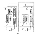
- FIG. 1 is a block diagram showing a solar power generation system and its peripheral devices in an embodiment according to the present invention.
- the solar power generation system 1 includes a solar cell block 10, a storage battery block 20, a power consumption prediction unit 32, a network unit 5, a control block 40, and a selection unit 4. Then, the photovoltaic power generation system 1 outputs power to the load 31 by utilizing the power supplied from the commercial power grid 2, the storage system 3, the solar battery 11, and the storage battery 21.
- the solar cell block 10 is configured to include a solar cell 11, a sunlight prediction unit 12, and a power conditioner 13.
- the solar cell 11 generates power in accordance with the amount of incident sunlight.
- the solar cell 11 is installed in a place where the incidence of sunlight is not easily blocked, for example, on the roof of a house.
- the power conditioner 13 performs DC / DC conversion or DC / AC conversion of the generated power of the solar cell 11.
- the sunlight prediction unit 12 predicts the amount of sunlight incident on the solar cell 11 in the future, and outputs information on the predicted amount of incident to the control block 40. Specifically, the sunlight prediction unit 12 observes the state of clouds in the vicinity of the installation location of the solar cell 11, analyzes the distribution of clouds in the near future, and injects sunlight into the solar cell 11 in the near future Predict the quantity.
- Such a function is realized, for example, by detecting the distribution and motion of clouds in the sky using a fisheye camera, and predicting the distribution of near-future clouds based on the detection result. In addition, such a function is also realized based on observation results of clouds using laser light.
- the sunlight prediction unit 12 predicts the distribution of clouds above the solar cell 11, it is installed near the solar cell 11.
- the sunlight prediction unit 12 may not necessarily be installed in the vicinity of the solar cell 11.
- the storage battery block 20 includes a storage battery 21, a detection unit 22, and a power conditioner 23.
- the storage battery 21 charges and stores the power supplied from the power system 2 and the solar cell block 10.
- the storage battery 21 is formed of a secondary battery, and for example, a lithium ion battery having a large volume energy density is used.
- the power conditioner 23 performs DC / DC conversion or DC / AC conversion of the power discharged from the storage battery 21 and DC / DC conversion or AC / DC conversion of the power supplied from the power system 2 and the solar cell block 10 to the storage battery 21. Convert.
- the detection unit 22 detects the remaining capacity of the storage battery 21 and outputs information on the remaining capacity to the control block 40.
- the detection unit 22 detects the remaining capacity based on, for example, the integrated value of the charge and discharge current.
- the network means 5 obtains charge / discharge plan information of the storage system 3 independent of the photovoltaic power generation system 1 and outputs it to the control block 40. Details of the storage system 3 will be described later.
- the selection means 4 is a means for selecting which one of the power system 2 or the storage system 3 is to preferentially supply power. Selection means 4 receives, for example, a state in which a large amount of power is supplied from power system 2 so as not to receive power supply from storage system 3, and a power from power system 2 receives a supply of power from storage battery system 3. Select a state to reduce the supply of
- the power consumption prediction unit 32 receives the history of the power consumption of the load 31, analyzes the time change information of the used power of the past, generates the predicted power consumption of the near future load 31, and outputs it to the control block 40 Do.
- the power consumption prediction unit 32 does not necessarily need to obtain the information from the load 31.
- the power consumption prediction unit 32 obtains fluctuation information of the power demand according to the season from a server (not shown). It may be generated.
- the power consumption prediction unit 32 may previously store a power consumption pattern of a predetermined load 31 as data, and the user may select from this pattern to generate predicted power of the near future load 31.
- the control block 40 includes a CPU 41, a display unit 42 and an input unit 43.
- the CPU 40 obtains information from the sunlight prediction unit 12, the power consumption prediction unit 32, the detection unit 22, and the network unit 5 and performs predetermined information processing, and outputs the result to the display unit 41.
- the display unit 42 displays the information obtained from the CPU 41 on a display and provides it to the user.
- the input unit 43 outputs a signal for controlling the selection unit 4 and the storage battery 21 when the user inputs a predetermined instruction.
- control block 40 The operation of the control block 40 will now be described with reference to FIG.
- the predicted power consumption, the predicted incident amount, and the remaining capacity are input to the control block 40.
- the predicted power consumption is input from the power consumption prediction unit 32, and indicates future power consumption based on the power consumption pattern of the load.
- the predicted incident amount is input from the solar light prediction unit 12 and indicates the future solar incident amount on the solar cell 11. In other words, the predicted incident amount corresponds to the predicted value of power generation of the solar cell 11 in the future.
- the remaining capacity is input from the detection unit 22 and indicates the remaining capacity of the storage battery 20.
- the control block 40 may be configured to instruct the storage battery 21 to charge the power from the power system 2 or the solar cell 11. Specifically, for example, at night, it is expected that the power consumption from the power system is low and the power consumption of the load is low. In such a case, at night, the control block 40 may instruct the storage battery 21 to charge the power from the power system 2 based on the remaining capacity. Also, for example, when the time when solar power generation peaks is different from the time when load power consumption reaches peak value, the time when solar power generation peaks is based on the remaining capacity. The storage battery 21 may be instructed to charge power from the solar cell 11. By doing so, it is possible to create a state in which storage battery 20 is sufficiently charged in a time zone in which the power consumption of load 31 reaches a peak value.
- the display unit 42 displays the predicted generated power of the solar cell 11 in the future based on the predicted incident amount. Generally, since the power generation of the solar cell 11 largely depends on the distribution of clouds above the installation location of the solar cell 11, it is difficult to accurately predict based on weather information. However, in the present embodiment, the display unit 42 displays the predicted generated power based on the distribution of clouds above the solar cell 11, so that the user can accurately grasp the predicted generated power in advance. .
- the CPU 41 calculates a predicted value of power to be supplied from the power system 2 in the future, based on the predicted power consumption, the predicted incident amount, and the remaining capacity. Specifically, the CPU 41 calculates the power that can be supplied from the solar cell 11 and the storage battery 21 to the load 31 without passing through the power system 2 from the predicted incident amount and the remaining capacity. Then, from the difference between this value and the predicted power consumption, the CPU 41 calculates the predicted value of the power to be supplied from the power system 2 in order to satisfy the predicted power consumption.
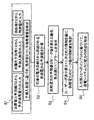
- step S3 when it is predicted that the predicted value of the supplied power from the power system 2 exceeds the peak value, the CPU 41 instructs the display unit 42 to display an alarm.
- step S4 when the alarm is displayed on the display unit 42, the user recognizes that the supplied power supplied from the power system 2 may exceed the peak value. Therefore, the user can consider measures to prevent the supplied power from exceeding the peak value based on the display. Specifically, for example, the user can suppress the use of the load 31 in order to suppress the power consumption of the load 31 in advance.
- the CPU 40 manages A signal may be output to a company or the like to control the solar power generation system 1.
- step S5 when the user determines that the power consumption of the load 31 can not be suppressed, the user performs a predetermined input to the input unit 43, and controls the selection unit 4. Thereby, power is supplied to the load 31 from the storage system 3. Then, the power supplied from power system 2 is suppressed, and the peak value of the power supplied from power system 2 is suppressed.
- the display unit 42 information on the remaining capacity and the like of the storage system 3 is displayed on the display unit 42 via the network means 5. For this reason, for example, when the plurality of storage systems 3 and the selection means 4 are connected, the user may select to supply power to the load 31 from the storage system 3 that is being charged in surplus. It becomes possible.
- the display content of the plurality of power storage systems 3 may be changed in the display unit 42 based on the remaining capacity and the like. For example, as the display unit 42 preferentially displays the storage system 3 with the largest remaining capacity, the user can easily select the storage system 3 with a good balance of supply and demand.
- the predicted generated power of sunlight is displayed on the display unit 42 of the solar cell 11. Then, since the sunlight prediction unit 12 predicts the amount of sunlight incident on the solar cell 11 based on the distribution of clouds in the vicinity of the solar cell 11, the display unit 42 predicts the predicted power generation of the solar cell 11. The power is accurately indicated. Therefore, the user can accurately know that the power generation from the solar cell 11 is insufficient by checking the display unit 42.
- an alarm is displayed on the display part 42 based on an alarm signal. Therefore, the user can grasp the possibility that the supplied power of the power system 2 exceeds the peak value without predicting the power consumption of the load by itself.
- the storage system 3 is configured to be charged and discharged independently of the solar power generation system 1.
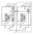
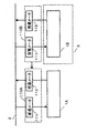
- FIG. 3 it connects with the storage battery 21 which comprises the other solar power generation system 1B at the selection means 4 of one solar power generation system 1A.
- the solar power generation systems 1A and 1B installed in the same area on weather information, in fact, there is a difference in the amount of sunlight incident on the solar cell 1 according to the distribution of clouds. It is happening. Therefore, in the solar cell systems 1A and 1B, a difference occurs in the power generation of the solar cells 11.
- the solar light prediction unit 12 can accurately predict the distribution of clouds above the solar cell 11 with high accuracy. For this reason, the solar power generation system 1A can obtain, via the network means 5, information of another solar power generation system 1B in which the power generation of the solar cell 11 is surplus.
- solar cell system 1A can receive supply of electric power from storage battery 21 which constitutes other solar cell system 1B, and can control electric power from electric power system 2.
- the solar power generation system 1A can analyze the distribution condition of the cloud in the installation place vicinity of the solar power generation system 1B by utilizing the information of the sunlight estimation part 12 in the solar power generation system 1B. Then, since the photovoltaic power generation system 1A can analyze the flow of the cloud based on the cloud distribution state in a wide range, the predicted distribution of the cloud can be analyzed more accurately.
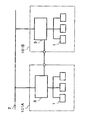
- communities 101A and 101B are provided for a plurality of solar power generation systems 1, and in each of communities 101A and 101B, a plurality of solar power generation systems 1 A storage system 3 common to the The storage system 3 is charge / discharge controlled independently of the respective solar power generation systems 1. Then, in the community 101A, when the solar power generation of a certain solar power generation system 1 is small and the power consumption of the load is large, the solar power generation system 1 receives the supply of electric power from the storage system 3, Suppress the power supplied from the power system 2. This can also be realized by the solar power generation system 1 having the sunlight prediction unit 12 and being able to accurately predict the power generation of the solar cell 11.
- each photovoltaic power generation system 1 may simultaneously receive power supply from the storage system 3. Then, it is assumed that the remaining capacity of power storage system 3 runs short. Assuming such a case, one community 101A may be configured to be able to receive the supply of power stored in the storage system 3 of another community 101B provided in another area. By doing in this way, each solar power generation system 1 can suppress the supplied power from the power grid 2 even if the entire solar power generation of the solar power generation system 1 belonging to the community is reduced. it can.
- the electrical storage system 3 may be used together as a buffer which performs charging / discharging for stabilization of the electric power grid
- the solar power generation system 1 includes the display unit 42. Then, the power generation of the solar cell 11 predicted by the sunlight prediction unit 12 is displayed by the display unit 42 and visually transmitted to the user.
- the present invention is not limited to this, and may be configured to transmit power generation of the solar cell 11 to the user by other means such as sound and light, for example. Such a configuration is realized, for example, by transmitting a warning to the user by sound, light or the like only when the predicted power generation of the solar cell 11 falls below a predetermined value.
- the solar power generation system 1 is provided with the selection means 4. Then, the solar power generation system 1 directly receives the supply of power from the storage system 3 independently of the power system 2.
- the present invention is not limited to this. That is, the solar power generation system 1 may not include the selection unit 4 and may receive the supply of power from the storage system 3 via the power system 2.
- the solar battery system 1 supplies the power from the storage system 3 with the amount of power supplied from the power company. It is assumed that it will be difficult to distinguish it from the
- the electricity purchase meter 111 not only the electricity purchase meter 111 but also the electricity sale meter 112 is provided between the photovoltaic power generation systems 1A, 1B and the electric power system 2 as the electricity meters 110A, 110B. Then, the supply and demand history of power is sequentially recorded in each of the power purchase meter 111 and the power sale meter 112.
- the power meters 110A and 110B can share information of power supply / supply history with each other. Then, for example, it is assumed that the solar power generation system 1A receives the supply of power from the solar power generation system 1B functioning as the storage system 3 via the power system 2 at a certain time.
- the data of the power purchase meter 111 in the solar power generation system 1A is adjusted based on the data of the power sale meter 112 of the solar power generation system 1B at that time.
- the power supply received by the solar power generation system 1A from the storage system 3 via the power system 2 can be measured.
- the solar power generation system 1A can substantially receive the supply of power from the storage system 3 via the power system 2.
- SYMBOLS 1 solar power generation system 2 electric power system, 3 electricity storage system, 4 selection means, 5 network means, 10 solar cell block, 11 solar cell, 12 solar light prediction unit, 20 storage battery block, 21 storage battery, 22 detection unit, 31 load , 32 power consumption prediction unit, 40 control block, 41 CPU, 42 display unit, 43 input unit, 101 community, 110 power meter, 111 power meter, 112 power meter.
Landscapes
- Engineering & Computer Science (AREA)
- Power Engineering (AREA)
- Supply And Distribution Of Alternating Current (AREA)
- Secondary Cells (AREA)
- Photovoltaic Devices (AREA)
- Charge And Discharge Circuits For Batteries Or The Like (AREA)
Abstract
太陽電池の発電低下を的確に把握することが困難であった。 本発明に係る太陽光発電システムは、太陽光の入射量に応じて電力を発電する太陽電池11と、前記太陽電池11の上空に位置する雲の分布を解析して、前記太陽電池11に入射される太陽光の予測入射量を出力する太陽光予測部12と、前記予測入射量に基づいた情報を知らせる伝達部(表示部42)と、を含んで構成されることを特徴とする。
Description
本発明は太陽光発電システム及びそのユーザーインターフェイス装置に関する。
近年、太陽電池及び蓄電池を備えた太陽光発電システムが開発されている。このシステムでは太陽電池によって発電された電力を蓄電池に充電することができる。このシステムを活用すると、商用の電力系統から供給される電力のピーク値を低減することができる。
例えば特許文献1には、日の出後であって電力需要がオフピークとなる時間帯に太陽電池からの発電によって蓄電池を充電するとともに、電力需要の高い特定の時間帯の電力需要の変動曲線に応じて蓄電池に蓄電された電力を放電する太陽光発電システムが開示されている。これによると、電力需要の高い特定の時間帯にのみ、太陽電池による発電と、蓄電池からの放電とによって負荷に電力を供給することが可能となるため、電池容量の小さな蓄電池を用いても、負荷の消費電力のピーク値を低減することができる。
また、特許文献1には、天気予報情報に基づいて翌日の天候状態を把握し、翌日の天候不順によって太陽電池の発電が少ないと予測した場合には、あらかじめ夜間に電力系統から電力を蓄電池に充電して、電力需要の高い時間帯に蓄電池の充電電力が不足することを回避する太陽光発電システムが開示されている。
この太陽光発電システムによると、電力需要の高い特定の時間帯における太陽電池の発電が予測値とのズレが生じる可能性が高かった。
つまり、太陽電池の発電は、太陽電池に照射される太陽光の入射量に大きく依存する。しかしながら、一般的な天気予報情報は一定の広範囲地域における平均的な天候情報である。このため、実際に太陽電池に照射される太陽光の入射量は、短時間単位では天候情報から概算された予測値とずれてしまう可能性が高かった。したがって、この太陽電池システムであっても、このズレを見積もって蓄電池の電池容量に余分を持たせる必要があった。
また、電力需要の高い時間帯において、例えば太陽電池の設置場所の近傍地域に雲が多い場合、長時間にわたって蓄電池を放電して負荷に電力を供給し続ける必要がある。このため、蓄電池の電池容量を小さくすると蓄電池が電力を放電し尽くしてしまいやすいため、結局は負荷の消費電力のピーク値が設定値を超えてしまう。そうすると、例えば、電力系統から供給される消費電力のピーク値に基づいて電力会社と電力使用料金を契約している場合であっても、予期せずに消費電力のピーク値を超えてしまう可能性があった。
本発明に係る太陽光発電システムは、太陽光の入射量に応じて電力を発電する太陽電池と、前記太陽電池の上空に位置する雲の分布を解析して、前記太陽電池に入射される太陽光の予測入射量を出力する太陽光予測部と、前記予測入射量に基づいた情報を知らせる伝達部と、を含んで構成されることを特徴とする。
また、本発明に係る太陽光発電システムのユーザーインターフェイス装置は、太陽光の入射量に応じて電力を発電する太陽電池の上空に位置する雲の分布を解析して、前記太陽電池に入射される太陽光の予測入射量に基づいた情報を知らせる伝達部を含んで構成されることを特徴とする。
本発明に係る太陽光発電システム及びそのユーザーインターフェイス装置によると、ユーザーは太陽電池の将来における発電を高い精度で認識することができる。
以下に、本発明に係る実施の形態について添付図面を参照しながら詳細に説明する。また、以下では、全ての図面において同様の要素には同一の符号を付し、重複する説明を省略する。そして、本文中の説明においては、必要に応じそれ以前に述べた符号を用いるものとする。
図1は、本発明に係る実施の形態において、太陽光発電システム及びその周辺機器を示すブロック図である。
太陽光発電システム1は、太陽電池ブロック10、蓄電池ブロック20、消費電力予測部32、ネットワーク手段5、制御ブロック40及び選択手段4を含んで構成される。そして、太陽光発電システム1は、商用の電力系統2、蓄電システム3、太陽電池11及び蓄電池21から供給される電力を活用して負荷31に電力を出力する。
太陽電池ブロック10は、太陽電池11、太陽光予測部12及びパワーコンディショナー13を含んで構成される。太陽電池11は、太陽光の入射量に応じて発電する。太陽電池11は、太陽光の入射が遮られ難い場所、例えば住宅の屋根上に設置される。パワーコンディショナー13は太陽電池11の発電電力をDC/DC変換又はDC/AC変換する。太陽光予測部12は将来における太陽電池11への太陽光の入射量を予測して、予測入射量の情報を制御ブロック40に出力する。具体的には、太陽光予測部12は太陽電池11の設置場所近傍の上空の雲の状態を観測して近未来の雲の分布を解析し、近未来の太陽電池11への太陽光の入射量を予測する。このような機能は、例えば魚眼カメラを用いて上空の雲の分布及び動きを検出し、当該検出結果に基づいて近未来の雲の分布を予測することによって実現される。また、このような機能は、レーザー光を用いた雲の観察結果に基づいても実現される。
このように太陽光予測部12は太陽電池11の上空の雲の分布を予測するものであるから太陽電池11の近傍に設置される。なお、例えば衛星を用いて太陽電池11の上空の雲の分布を予測できれば、必ずしも太陽光予測部12は太陽電池11の近傍に設置されなくてもよい。
蓄電池ブロック20は、蓄電池21、検出部22及びパワーコンディショナー23を含んで構成される。蓄電池21は、電力系統2及び太陽電池ブロック10から供給される電力を充電して貯蔵する。蓄電池21は二次電池からなり、例えば体積エネルギー密度の大きいリチウムイオン電池が用いられる。パワーコンディショナー23は、蓄電池21から放電された電力をDC/DC変換又はDC/AC変換するとともに、電力系統2及び太陽電池ブロック10から蓄電池21に供給される電力をDC/DC変換又はAC/DC変換する。検出部22は、蓄電池21の残容量を検出して、残容量の情報を制御ブロック40に出力する。検出部22は、例えば充放電電流の積算値に基づいて残容量を検出する。
ネットワーク手段5は、太陽光発電システム1と独立した蓄電システム3の充放電計画情報を入手して制御ブロック40に出力する。蓄電システム3の詳細は後述する。
選択手段4は、電力系統2又は蓄電システム3のいずれから電力が優先的に供給されるのかを選択する手段である。選択手段4は、例えば、蓄電システム3から電力の供給を受けないようにして電力系統2から多くの電力の供給を受ける状態と、蓄電池システム3から電力の供給を受けて電力系統2からの電力の供給を低減させる状態と、を選択する。
消費電力予測部32は、負荷31の消費電力の履歴が入力されて過去の負荷の使用電力の時間変化情報を解析し、近未来の負荷31の予測消費電力を生成して制御ブロック40に出力する。消費電力予測部32は、必ずしも負荷31からの情報を入手する必要はなく、例えば、図示しないサーバーから季節に応じた電力需要の変動情報を入手して、近未来の負荷31の予測消費電力を生成してもよい。また、消費電力予測部32は、あらかじめ所定の負荷31の電力消費パターンをデータとしてストックしており、ユーザーがこのパターンから選択して、近未来の負荷31の予測電力を生成してもよい。
制御ブロック40は、CPU41、表示部42及び入力部43を含んで構成される。CPU40は、太陽光予測部12、消費電力予測部32、検出部22及びネットワーク手段5から情報を入手するとともに所定の情報処理を行い、その結果を表示部41に出力する。表示部42は、CPU41から得られた情報をディスプレイに表示してユーザーに提供する。入力部43は、ユーザーが所定の指示を入力することによって、選択手段4や蓄電池21を制御する信号を出力する。
ここで、図2を参照して、制御ブロック40の動作について説明する。
はじめに、ステップS1に示すように、制御ブロック40には、予測消費電力、予測入射量及び残容量が入力される。予測消費電力は、消費電力予測部32から入力され、負荷の電力消費パターンに基づく将来の消費電力を示す。予測入射量は、太陽光予測部12から入力され、将来の太陽電池11への太陽光入射量を示す。言い換えれば、予測入射量は、将来の太陽電池11の発電の予測値に相当する。残容量は、検出部22から入力され、蓄電池20の残容量を示す。
ここで、必要に応じて、制御ブロック40は、蓄電池21に対して、電力系統2又は太陽電池11から電力を充電するように指示するように構成してもよい。具体的に説明すると、例えば、夜間においては、電力系統からの電力使用量が低廉であり、負荷の消費電力が低いことが予想される。このような場合には、夜間には、制御ブロック40は、残容量に基づいて、蓄電池21に対して、電力系統2から電力を充電するように指示するとよい。また、例えば、太陽光発電がピークになる時間帯と、負荷の消費電力がピーク値になる時間帯とが異なる場合には、太陽光発電がピークになる時間帯には、残容量に基づいて、蓄電池21に対して、太陽電池11から電力を充電するように指示するとよい。そうすることで、負荷31の消費電力がピーク値になる時間帯において、蓄電池20が十分に充電されている状態をつくることができる。
表示部42は、予測入射量に基づいて、将来における太陽電池11の予測発電電力を表示する。一般的に、太陽電池11の発電は、太陽電池11の設置場所の上空の雲の分布状況に大きく左右されるため、気象情報に基づいて正確に予測することは困難である。しかし、本実施形態では、表示部42は、太陽電池11の上空の雲の分布状況に基づいた予測発電電力を表示するため、ユーザーは事前に予測発電電力を的確に把握することが可能となる。
つぎに、ステップS2に示すように、CPU41は、予測消費電力、予測入射量、残容量に基づいて、将来、電力系統2から供給されるべき電力の予測値を算出する。具体的に説明すると、予測入射量と残容量とから、CPU41は、電力系統2を介さずに太陽電池11及び蓄電池21から負荷31に供給できる電力を算出する。そして、この値と予測消費電力との差分から、CPU41は、予測消費電力を満たすために電力系統2から供給されるべき電力の予測値を算出する。
つぎに、ステップS3に示すように、電力系統2からの供給電力の予測値がピーク値を超えると予測された場合、CPU41は、表示部42に対してアラームを表示するように指示する。
つぎに、ステップS4に示すように、表示部42にアラームが表示されると、ユーザーは、電力系統2から供給される供給電力がピーク値を超える可能性があることを把握する。このため、ユーザーは、この表示を基にして、供給電力がピーク値を超えないように対策を検討することができる。具体的には、例えば、ユーザーは、負荷31の消費電力を事前に抑制するために、負荷31の使用を抑制することができる。なお、ユーザーが長時間にわたって表示部42を確認できない状況にも対応できるように、例えば、表示部42に所定の信号が表示されてから長時間にわたってユーザーから応答がない場合には、CPU40は管理会社などに太陽光発電システム1を制御するように信号を出力するようにしてもよい。
つぎに、ステップS5に示すように、ユーザーが負荷31の消費電力を抑制できないと判断した場合などにおいて、ユーザーは入力部43に所定の入力を行い、選択手段4を制御する。これにより、負荷31には、蓄電システム3から電力が供給されるようになる。そうすると、電力系統2から供給される電力が抑制され、電力系統2からの供給電力のピーク値が抑制される。
ここで、表示部42には、ネットワーク手段5を介して蓄電システム3の残容量などに関する情報が表示される。このため、例えば、複数の蓄電システム3と選択手段4とが接続されている場合には、ユーザーは、余剰に充電されている蓄電システム3から負荷31に電力を供給するように選択することが可能となる。また、好ましくは、表示部42には、残容量などに基づいて複数の蓄電システム3の表示内容を変更するとよい。例えば、表示部42が最も残容量の大きい蓄電システム3を優先的に表示することによって、ユーザーは容易に需給バランスのよい蓄電システム3を選択することができる。
このように、太陽光発電システム1では、太陽電池11の表示部42に太陽光の予測発電電力が表示される。そして、太陽光予測部12は、太陽電池11の近傍における雲の分布を基にして太陽電池11への太陽光の入射量を予測しているため、表示部42には太陽電池11の予測発電電力が精度よく示される。このため、ユーザーは、表示部42を確認することによって、太陽電池11からの発電が不足することを精度よく知ることができる。
また、太陽光発電システム1では、アラーム信号に基づいて表示部42にアラームが表示される。このため、ユーザーは、自ら負荷の消費電力を予測しなくても電力系統2の供給電力がピーク値を超える可能性を把握できる。
そして、太陽光発電システム1では、蓄電システム3から電力の供給を受けることができるため、蓄電池21の残容量が足りなくなっても、電力系統2からの供給電力がピーク値を超えることなく負荷31に電力を供給することができる。
つづいて、蓄電システム3の各種形態について説明する。前述したとおり、蓄電システム3は、太陽光発電システム1と独立して充放電するように構成されている。
このような形態として、図3に示すように、一の太陽光発電システム1Aの選択手段4には、他の太陽光発電システム1Bを構成する蓄電池21と接続される。気象情報上では同一地域内に設置された太陽光発電システム1A、1Bであっても、実際には雲の分布状況に応じて、太陽電池1に入射される太陽光の入射量には差が生じている。このため、太陽電池システム1A,1Bでは、太陽電池11の発電に差が生じる。この点、太陽光予測部12は、太陽電池11の上空における雲の分布状況を精度よく予測できる。このため、太陽光発電システム1Aは、ネットワーク手段5を介して、太陽電池11の発電が余剰になる他の太陽光発電システム1Bの情報を入手することができる。そして、太陽電池システム1Aは、他の太陽電池システム1Bを構成する蓄電池21から電力の供給を受けて、電力系統2からの電力を抑制することができる。なお、太陽光発電システム1Aは、太陽光発電システム1Bにおける太陽光予測部12の情報を活用することによって、太陽光発電システム1Bの設置場所近傍における雲の分布状況を解析することができる。そうすると、太陽光発電システム1Aは、広範囲における雲の分布状況に基づいて雲の流れを解析することができるため、より正確に雲の予測分布を解析できる。
また、蓄電システム3の他の形態として、図4に示すように、複数の太陽光発電システム1に対してコミュニティ101A、101Bを設け、それぞれのコミュニティ101A、101Bにおいて、複数の太陽光発電システム1に共通する蓄電システム3を設けてもよい。この蓄電システム3は、それぞれの太陽光発電システム1とは独立して充放電制御される。そして、コミュニティ101Aにおいて、ある太陽光発電システム1の太陽光発電が小さく、かつ、負荷の消費電力が多いような場合、この太陽光発電システム1は蓄電システム3から電力の供給を受けることにより、電力系統2からの供給電力を抑制する。これも、太陽光発電システム1が太陽光予測部12を有して太陽電池11の発電を精度よく予測できることによって実現できるものである。この形態において、一のコミュニティ101Aに属する複数の太陽光発電システム1の地域全体の天候が不順となると、それぞれの太陽光発電システム1が同時に蓄電システム3から電力の供給を受ける場合がある。そうすると、蓄電システム3の残容量が不足することが想定される。このような場合を想定して、一のコミュニティ101Aは、他地域に設けられた他のコミュニティ101Bの蓄電システム3に蓄電された電力の供給を受けることができるように構成されてもよい。このようにすることで、コミュニティに属する太陽光発電システム1の全体の太陽光発電が低下する場合であっても、それぞれの太陽光発電システム1は電力系統2からの供給電力を抑制することができる。
当該構成においては、蓄電システム3は、電力系統2の周波数が変動したときに、電力系統2の安定化のために充放電を行うバッファーとして併用されてもよい。
なお、上記実施例は本発明の理解を容易にするためのものであり、本発明を限定して解釈するためのものではない。本発明は、その趣旨を逸脱することなく、変更、改良され得ると共に、本発明にはその等価物も含まれる。
例えば、上記実施例では、太陽光発電システム1は表示部42を備えていた。そして、太陽光予測部12によって予測された太陽電池11の発電は、表示部42によって表示されて視覚的にユーザーに伝達されていた。しかしながら、本発明はこれに限定されず、例えば、音、光など他の手段によって太陽電池11の発電をユーザーに伝達できるように構成されてもよい。このような構成は、例えば、予測された太陽電池11の発電が所定値を下回った場合にのみ音、光などによってユーザーに警告するように伝達することによって実現される。
また、例えば、上記実施例では、太陽光発電システム1は選択手段4を備えていた。そして、太陽光発電システム1は、電力系統2とは独立して、蓄電システム3から電力の供給を直接受けていた。しかしながら、本発明はこれに限定されない。つまり、太陽光発電システム1は選択手段4を備えず、電力系統2を介して、蓄電システム3から電力の供給を受けても良い。
このように、電力系統2を介して、太陽光発電システム1が蓄電システム3から電力の供給を受ける場合、太陽電池システム1が電力会社から電力を供給された量と蓄電システム3から電力を供給された量との判別が困難になることが想定される。
そこで、図6に示すように、太陽光発電システム1A、1Bと電力系統2との間には、電力メータ110A、110Bとして、買電メータ111のみならず売電メータ112を設ける。そして、それぞれの買電メータ111及び売電メータ112には、電力の供給・需給履歴を逐次記録する。このような構成において、電力メータ110A,110Bは互いに電力の供給・需給履歴の情報を共有できるようにする。そうすると、例えば、ある時間において、太陽光発電システム1Aが蓄電システム3として機能する太陽光発電システム1Bから電力系統2を介して電力の供給を受けたとする。この場合、当該時間における太陽光発電システム1Bの売電メータ112のデータをもとにして、太陽光発電システム1Aにおける買電メータ111のデータを調整する。これによって、太陽光発電システム1Aが電力系統2を介して蓄電システム3から受けた供給電力を計測することができる。このような構成によって、実質的に、太陽光発電システム1Aは、電力系統2を介して蓄電システム3から電力の供給を受けることができる。
1 太陽光発電システム、2 電力系統、3 蓄電システム、4 選択手段、5 ネットワーク手段、10 太陽電池ブロック、11 太陽電池、12 太陽光予測部、20 蓄電池ブロック、21 蓄電池、22 検出部、31 負荷、32 消費電力予測部、40 制御ブロック、41 CPU、42 表示部、43 入力部、101 コミュニティ、110 電力メータ、 111 買電メータ、112 売電メータ。
Claims (12)
- 太陽光の入射量に応じて電力を発電する太陽電池と、
前記太陽電池の上空に位置する雲の分布を解析して、前記太陽電池に入射される太陽光の予測入射量を出力する太陽光予測部と、
前記予測入射量に基づいた情報を知らせる伝達部と、を含んで構成されること、を特徴とする太陽光発電システム。 - 請求項1に記載の太陽光発電システムにおいて、
前記伝達部は、前記予測入射量に基づいた情報を表示する表示部を含んで構成されること、を特徴とする太陽光発電システム。 - 請求項1または2のいずれかに記載の太陽光発電システムにおいて、
前記太陽光予測部は前記太陽電池に近接して設けられたカメラによって前記太陽電池の上空に位置する雲の分布を予測する機能を有すること、を特徴とする太陽光発電システム。 - 請求項1~3のいずれかに記載の太陽光発電システムにおいて、
電力系統又は前記太陽電池の少なくとも一方から供給される電力を蓄電する蓄電池を含んで構成され、
少なくとも前記電力系統及び前記蓄電池から負荷に電力を供給することを特徴とする太陽光発電システム。 - 請求項4に記載の太陽光発電システムにおいて、
前記太陽電池、前記蓄電池、前記負荷及び前記太陽電池予測部と独立して設けられた蓄電システムから前記負荷に電力を供給させる指示信号を生成する制御部を有すること、を特徴とする太陽光発電システム。 - 請求項5に記載の太陽光発電システムにおいて、
前記蓄電システムは、少なくとも前記太陽電池、前記蓄電池及び前記太陽光予測部を含んで構成されること、を特徴とする太陽光発電システム。 - 請求項6に記載の太陽光発電システムにおいて、
前記負荷は、複数の前記蓄電システムから電力の供給を受けることができるように構成され、
前記伝達部は、前記蓄電システムのいずれから優先的に前記負荷に電力を供給させるのかを選択するための情報を知らせる機能を備えること、を特徴とする太陽光発電システム。 - 請求項5~7のいずれかに記載の太陽光発電システムにおいて、
前記蓄電システムは、前記電力系統とは別途設けられた電力線を介して前記負荷に電力を供給するように構成されていること、を特徴とする太陽光発電システム。 - 請求項5~7のいずれかに記載の太陽光発電システムにおいて、
前記蓄電システムは、前記電力系統を介して前記負荷に電力を供給するように構成されていること、を特徴とする太陽光発電システム。 - 太陽光の入射量に応じて電力を発電する太陽電池の上空に位置する雲の分布を解析して、前記太陽電池に入射される太陽光の予測入射量に基づいた情報を知らせる伝達部を含んで構成されること、を特徴とする太陽光発電システムのユーザーインターフェイス装置。
- 請求項10に記載の太陽光発電システムのユーザーインターフェイス装置において、
前記伝達部は、前記予測入射量に基づいた情報を表示する表示部を含んで構成されること、を特徴とする太陽光発電システムのユーザーインターフェイス装置。 - 請求項10または11のいずれかに記載の太陽光発電システムのユーザーインターフェイス装置において、
前記予測入射量は、前記太陽電池に近接して設けられたカメラによって前記太陽電池の上空に位置する雲の分布を予測して得られた情報であること、を特徴とする太陽光発電システムのユーザーインターフェイス装置。
Applications Claiming Priority (2)
| Application Number | Priority Date | Filing Date | Title |
|---|---|---|---|
| JP2010-126222 | 2010-06-01 | ||
| JP2010126222A JP2013165533A (ja) | 2010-06-01 | 2010-06-01 | 太陽光発電システム及びそのユーザーインターフェイス装置 |
Publications (1)
| Publication Number | Publication Date |
|---|---|
| WO2011152448A1 true WO2011152448A1 (ja) | 2011-12-08 |
Family
ID=45066806
Family Applications (1)
| Application Number | Title | Priority Date | Filing Date |
|---|---|---|---|
| PCT/JP2011/062585 Ceased WO2011152448A1 (ja) | 2010-06-01 | 2011-06-01 | 太陽光発電システム及びそのユーザーインターフェイス装置 |
Country Status (2)
| Country | Link |
|---|---|
| JP (1) | JP2013165533A (ja) |
| WO (1) | WO2011152448A1 (ja) |
Cited By (3)
| Publication number | Priority date | Publication date | Assignee | Title |
|---|---|---|---|---|
| JP2013179790A (ja) * | 2012-02-29 | 2013-09-09 | Lecip Holdings Corp | 充電制御装置 |
| US10133245B2 (en) | 2013-11-11 | 2018-11-20 | Tmeic Corporation | Method for predicting and mitigating power fluctuations at a photovoltaic power plant due to cloud cover |
| US11444473B2 (en) | 2019-10-15 | 2022-09-13 | Inventus Holdings, Llc | Dynamic battery charging for maximum wind/solar peak clipping recapture |
Families Citing this family (4)
| Publication number | Priority date | Publication date | Assignee | Title |
|---|---|---|---|---|
| JP5969438B2 (ja) * | 2013-08-23 | 2016-08-17 | 株式会社 日立産業制御ソリューションズ | 太陽光発電システム及び太陽光発電制御方法 |
| JP6235408B2 (ja) * | 2014-05-13 | 2017-11-22 | 株式会社 日立産業制御ソリューションズ | 発電システム、計画装置、および制御方法 |
| JP6551433B2 (ja) | 2017-02-10 | 2019-07-31 | トヨタ自動車株式会社 | 太陽光発電制御装置 |
| JP7442354B2 (ja) * | 2020-03-17 | 2024-03-04 | 大阪瓦斯株式会社 | 太陽光発電システム及び太陽光発電システムの運転方法 |
Citations (6)
| Publication number | Priority date | Publication date | Assignee | Title |
|---|---|---|---|---|
| JP2003121558A (ja) * | 2001-10-12 | 2003-04-23 | Canon Inc | 情報処理装置およびその方法 |
| JP2003244854A (ja) * | 2002-02-13 | 2003-08-29 | Mitsubishi Heavy Ind Ltd | 蓄電装置の充放電制御装置及び充放電制御方法並びに電力貯蔵システム |
| JP2005312163A (ja) * | 2004-04-20 | 2005-11-04 | Canon Inc | 発電制御装置及び発電システム |
| JP2006210750A (ja) * | 2005-01-31 | 2006-08-10 | Sanyo Electric Co Ltd | 発電量予測システムおよび発電量予測方法 |
| JP2007037226A (ja) * | 2005-07-25 | 2007-02-08 | Mitsubishi Electric Corp | 電源システムおよびその制御方法 |
| JP2007184354A (ja) * | 2006-01-05 | 2007-07-19 | Mitsubishi Electric Corp | 太陽光発電システム |
-
2010
- 2010-06-01 JP JP2010126222A patent/JP2013165533A/ja active Pending
-
2011
- 2011-06-01 WO PCT/JP2011/062585 patent/WO2011152448A1/ja not_active Ceased
Patent Citations (6)
| Publication number | Priority date | Publication date | Assignee | Title |
|---|---|---|---|---|
| JP2003121558A (ja) * | 2001-10-12 | 2003-04-23 | Canon Inc | 情報処理装置およびその方法 |
| JP2003244854A (ja) * | 2002-02-13 | 2003-08-29 | Mitsubishi Heavy Ind Ltd | 蓄電装置の充放電制御装置及び充放電制御方法並びに電力貯蔵システム |
| JP2005312163A (ja) * | 2004-04-20 | 2005-11-04 | Canon Inc | 発電制御装置及び発電システム |
| JP2006210750A (ja) * | 2005-01-31 | 2006-08-10 | Sanyo Electric Co Ltd | 発電量予測システムおよび発電量予測方法 |
| JP2007037226A (ja) * | 2005-07-25 | 2007-02-08 | Mitsubishi Electric Corp | 電源システムおよびその制御方法 |
| JP2007184354A (ja) * | 2006-01-05 | 2007-07-19 | Mitsubishi Electric Corp | 太陽光発電システム |
Cited By (3)
| Publication number | Priority date | Publication date | Assignee | Title |
|---|---|---|---|---|
| JP2013179790A (ja) * | 2012-02-29 | 2013-09-09 | Lecip Holdings Corp | 充電制御装置 |
| US10133245B2 (en) | 2013-11-11 | 2018-11-20 | Tmeic Corporation | Method for predicting and mitigating power fluctuations at a photovoltaic power plant due to cloud cover |
| US11444473B2 (en) | 2019-10-15 | 2022-09-13 | Inventus Holdings, Llc | Dynamic battery charging for maximum wind/solar peak clipping recapture |
Also Published As
| Publication number | Publication date |
|---|---|
| JP2013165533A (ja) | 2013-08-22 |
Similar Documents
| Publication | Publication Date | Title |
|---|---|---|
| JP5481080B2 (ja) | 電力融通システム | |
| US9153963B2 (en) | Electric power control apparatus and grid connection system having same | |
| US8571720B2 (en) | Supply-demand balance controller | |
| US9293915B2 (en) | Electric power control device and electric power control system using same | |
| EP2475060B1 (en) | Energy storage system | |
| KR101075958B1 (ko) | 분산전원의 전력 거래 시스템 및 거래 방법 | |
| JP6145670B2 (ja) | 電力潮流制御システム、管理装置、プログラム | |
| US8788110B2 (en) | Electric power visualization method and electric power visualization device | |
| KR101845703B1 (ko) | 수요전력제어 최적화 기술의 ems를 적용한 에너지저장시스템 | |
| EP2701261A1 (en) | Control device, power control system, and power control method | |
| JP6122364B2 (ja) | 電力制御装置、電力制御方法及び電力制御プログラム | |
| EP2418754A2 (en) | Power-fluctuation reducing apparatus for power generation system | |
| JP6426922B2 (ja) | 電力システム、御装置及び充放電制御方法 | |
| JP2011083058A (ja) | 電力供給システムの蓄電池電力供給源監視装置 | |
| JP2011130638A (ja) | 自然エネルギを用いた発電システム | |
| JP2011182555A (ja) | 電力供給システム | |
| JP2011250673A (ja) | エネルギーコントローラおよび制御方法 | |
| JP2013165533A (ja) | 太陽光発電システム及びそのユーザーインターフェイス装置 | |
| JP6522901B2 (ja) | 直流配電システム | |
| JP2017108560A (ja) | 電力融通システムの制御装置および制御プログラム | |
| WO2016002346A1 (ja) | 電力制御システム及び電力制御装置 | |
| EP2849302B1 (en) | Energy management device, energy management method and program | |
| JP2015195696A (ja) | 電力管理システム、電力管理方法およびサーバ | |
| US20150025702A1 (en) | Energy management system | |
| JP5752069B2 (ja) | 電力制御システム |
Legal Events
| Date | Code | Title | Description |
|---|---|---|---|
| 121 | Ep: the epo has been informed by wipo that ep was designated in this application |
Ref document number: 11789850 Country of ref document: EP Kind code of ref document: A1 |
|
| NENP | Non-entry into the national phase |
Ref country code: DE |
|
| 122 | Ep: pct application non-entry in european phase |
Ref document number: 11789850 Country of ref document: EP Kind code of ref document: A1 |
|
| NENP | Non-entry into the national phase |
Ref country code: JP |