WO2011152271A1 - 太陽電池モジュール - Google Patents
太陽電池モジュール Download PDFInfo
- Publication number
- WO2011152271A1 WO2011152271A1 PCT/JP2011/062057 JP2011062057W WO2011152271A1 WO 2011152271 A1 WO2011152271 A1 WO 2011152271A1 JP 2011062057 W JP2011062057 W JP 2011062057W WO 2011152271 A1 WO2011152271 A1 WO 2011152271A1
- Authority
- WO
- WIPO (PCT)
- Prior art keywords
- solar cell
- back sheet
- cell module
- cell panel
- frame
- Prior art date
- Legal status (The legal status is an assumption and is not a legal conclusion. Google has not performed a legal analysis and makes no representation as to the accuracy of the status listed.)
- Ceased
Links
Images



Classifications
-
- H—ELECTRICITY
- H10—SEMICONDUCTOR DEVICES; ELECTRIC SOLID-STATE DEVICES NOT OTHERWISE PROVIDED FOR
- H10F—INORGANIC SEMICONDUCTOR DEVICES SENSITIVE TO INFRARED RADIATION, LIGHT, ELECTROMAGNETIC RADIATION OF SHORTER WAVELENGTH OR CORPUSCULAR RADIATION
- H10F19/00—Integrated devices, or assemblies of multiple devices, comprising at least one photovoltaic cell covered by group H10F10/00, e.g. photovoltaic modules
- H10F19/80—Encapsulations or containers for integrated devices, or assemblies of multiple devices, having photovoltaic cells
- H10F19/85—Protective back sheets
-
- Y—GENERAL TAGGING OF NEW TECHNOLOGICAL DEVELOPMENTS; GENERAL TAGGING OF CROSS-SECTIONAL TECHNOLOGIES SPANNING OVER SEVERAL SECTIONS OF THE IPC; TECHNICAL SUBJECTS COVERED BY FORMER USPC CROSS-REFERENCE ART COLLECTIONS [XRACs] AND DIGESTS
- Y02—TECHNOLOGIES OR APPLICATIONS FOR MITIGATION OR ADAPTATION AGAINST CLIMATE CHANGE
- Y02E—REDUCTION OF GREENHOUSE GAS [GHG] EMISSIONS, RELATED TO ENERGY GENERATION, TRANSMISSION OR DISTRIBUTION
- Y02E10/00—Energy generation through renewable energy sources
- Y02E10/50—Photovoltaic [PV] energy
Definitions
- the present invention relates to a solar cell module, and more particularly to a solar cell module that prevents moisture from entering the solar cell module.
- a solar cell In a solar cell panel, a solar cell is sealed and protected by a sealing resin between glass and a back sheet. In many cases, a frame is attached around such a solar cell panel and installed outdoors.
- a solar cell module has also been proposed in which the back sheet is formed in advance so that the outer peripheral edge portion protrudes from the outer peripheral portion of the laminate of the solar cell panel, and the back sheet is adhered to the side end face to protect (for example, Patent Document 2).
- An object of the present invention is to provide a solar cell module which can further prevent the infiltration of moisture from the side end face of the solar cell panel and can suppress the deterioration of the solar cell, the electrode and the like.
- a solar cell module according to the present invention is a solar cell module having a solar cell panel provided with a plurality of solar cells sealed with a resin between the back sheets, wherein the back sheet is at least the light transmitting member. It is formed in such a size that it protrudes from the long side of the transparent substrate, and is bonded so that at least the side end face of the light transmitting substrate on the long side is protected by the back sheet.
- the back sheet may be bent to the light receiving surface side of the light transmitting substrate, and may be bonded to the light receiving surface side of the light transmitting substrate.
- a frame may be attached around the solar cell panel, and an end face of the back sheet may be accommodated in the frame and connected to the translucent substrate.
- the back sheet may be configured to be folded at the end face portion and adhered to the light transmitting substrate.
- end face of the back sheet may be covered with a resin.
- the back sheet having excellent weather resistance covering the back surface of the solar cell panel continuously covers the side end face of the solar cell panel as it is, it is possible to reliably prevent the intrusion of moisture into the layers of the solar cell panel. Can.
- the end of the back sheet is also bent to prevent direct exposure to the upper surface of the glass. This prevents moisture and the like from entering between the base material of the back sheet and the barrier layer, and the durability of the back sheet is also improved.
- FIG. 1 It is a top view which shows embodiment of the solar cell module concerning this invention. It is a typical sectional view showing each composition of a solar cell panel concerning an embodiment of this invention.
- FIG. 1 is a plan view showing an embodiment of a solar cell module according to the present invention, showing a frame attached to a solar cell panel.
- a solar cell module 100 has a solar cell panel 10 formed by resin sealing a plurality of solar cells 1 and a frame 7 surrounding the entire outer periphery of the solar cell panel 10.
- the solar cell panel 10 is formed in a substantially rectangular shape in plan view.
- rectangular glass as a light transmitting substrate is disposed on the light receiving surface side, and a plurality of solar cells 1 connected by the tabs 11 are arranged side by side in series or in parallel on the back surface side of the glass.
- the plurality of solar cells 1 are sealed with a back sheet such as PET (polyethylene terephthalate) through a sealing resin such as EVA (ethylene vinyl acetate).
- the plurality of solar cells 1 connected in series by the tabs 11 constitute a string 110 which is one unit.
- the strings 110 are connected by connection wiring, so-called crossover wiring 111. Furthermore, a part of the crossover wiring 111 is used as a lead wire for drawing the output from the solar cell 11 to the outside.
- the frame 7 is manufactured by extruding a metal such as aluminum, and has a U-shaped portion having a U-shaped cross section over the entire circumference, and the outer edge of the solar cell panel 10 is completely covered with this U-shaped portion. Covering around the circumference.
- the frame 7 is fixed to the solar cell panel 10 via a butyl-based sealing material, a silicon-based adhesive, or the like to reinforce the solar cell panel 10 and provide the solar cell panel 10 in a building such as a house or a building It is attached to the mounted stand.
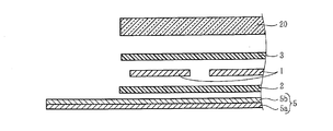
- FIG. 2 is a schematic cross-sectional view showing each configuration of the solar cell panel according to the embodiment of the present invention
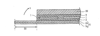
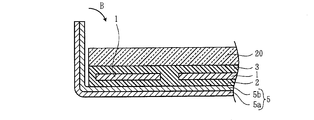
- FIGS. 3 and 4 are schematic cross-sectional views showing how a bent portion is bent
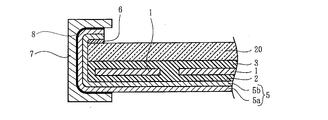
- FIG. It is a typical sectional view showing a solar cell module concerning a 1 embodiment.
- the sealing material sheets 2 and 3 are crosslinked to seal the solar cell 1 between the glass 20 and the back sheet 5 with a sealing material such as EVA resin.
- the respective members are stacked on a glass 20 and held in a crucible evacuated to about 100 Pa. Thereafter, the whole is heated to about 150 ° C., and pressure bonding is performed from the back sheet 5 side with a silicone sheet using atmospheric pressure.
- the sealing material sheets 2 and 3 are softened and temporary bonding is performed, the sealing material sheets 2 and 3 are crosslinked by holding the sealing material sheets 2 and 3 in a constant temperature oven at about 150 ° C. for a predetermined time.
- the laminate constituting the solar cell panel 10 is, from the light receiving surface side, a glass 20, a sealing material sheet 3, a solar cell 1, a sealing material sheet 2, PET or PVF (polyvinyl fluoride) And the like, which are excellent in weather resistance, are laminated in this order.
- the back sheet 5 is provided with a barrier layer 5 b on a base film 5 a of PET, PVF (polyvinyl fluoride) or the like, which is excellent in weather resistance.
- the barrier layer 5b is a thin film layer formed by vapor deposition of silicon oxide, aluminum oxide, magnesium oxide or a mixture thereof on the base film 5a.
- the back sheet 5 of 2 layer structure is shown here, the structure of 3 or more layers, such as a sandwich structure which pinched
- At least 2 sides of the long side of glass 20 are predetermined from the thickness of the solar cell panel 10 It has been used longer than the length. Of course, it is more effective if the four sides are made longer, but the effect can be expected only by protecting at least the long side.
- the sealing material sheets 2 and 3 are integrated by heat treatment to form a sealing resin layer for sealing the solar cell 1 with resin.
- the bent portion 50 of the back sheet 5 is bent 90 degrees on the side end face of the solar cell panel 10 having such a configuration, and further bent 90 degrees on the surface side of the glass substrate 20 It is adhered via a highly adhesive 6.
- the back sheet 5 is previously made larger by the width reaching the surface of the glass 20 by bending it, and the bent portion 50 is, as shown in FIG. 3 to FIG. It is bent 90 degrees to the side end face side in the direction, and is further bent 90 degrees to the surface side of the glass 20 to which the adhesive layer 6 is applied in the direction of the arrow B and bonded.
- the bent portion 50 covers the side end surface of the laminate constituting the solar cell panel 10 and serves as a protective layer.
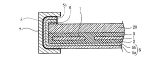
- the back sheet 5 with excellent weather resistance covering the back surface of the solar cell panel 10 continuously covers the side end face of the solar cell panel 10 as it is. Water can be more reliably prevented from entering. Further, the end portion of the back sheet 5 is also bent to the surface side, and the interface between the base 5 a of the back sheet 5 and the barrier layer 5 b is prevented from being directly exposed on the upper surface of the glass. This prevents moisture and the like from entering between the base material 5 a of the back sheet 5 and the barrier layer 5 b, and the durability of the back sheet 5 is also improved. As a result, the deterioration of the solar cell 1 or the tab can be suppressed, and the resistance against the deterioration is improved.
- the frame 7 is fixed around the solar cell panel 10 via a fixing material 8 such as a butyl-based sealing material or a silicon-based adhesive.
- a fixing material 8 such as a butyl-based sealing material or a silicon-based adhesive.
- the end face of the back sheet 5 is accommodated in the frame 7.
- the reliability is further improved by applying a butyl-based sealing material or a silicon-based adhesive 8 a to the end face of the back sheet 5.
- the bending part 50 of this embodiment is bend
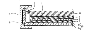
- FIG. 7 is a schematic cross-sectional view showing a solar cell module according to a second embodiment of the present invention.
- the front end portion of the back sheet 5 is bent 180 degrees, and then the end face side of the glass 20 is adhered with an adhesive 6.
- the frame 7 is fixed around the solar cell panel 10 via a fixing material 8 such as a butyl-based sealing material or a silicon-based adhesive.
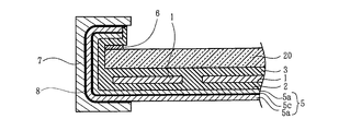
- FIG. 8 is a schematic cross-sectional view showing a solar cell module according to a third embodiment of the present invention.
- the front end of the back sheet 5 is folded by 180 degrees and bent, and then the surface of the glass 20 is adhered with an adhesive 6.
- the frame 7 is fixed around the solar cell panel 10 via a fixing material 8 such as a butyl-based sealing material or a silicon-based adhesive.
- the end face of the back sheet 5 can be bonded to the glass 20 without being exposed to the outside. As a result, the infiltration of water or the like to the end face portion of the back sheet 5 is further suppressed.
- FIG. 9 is a schematic cross-sectional view showing a solar cell panel according to a fourth embodiment of the present invention
- FIG. 10 is a schematic cross-sectional view showing a solar cell module according to the fourth embodiment of the present invention.
- the back sheet 5 is formed by using an aluminum foil 5c as a barrier layer and sandwiching the aluminum foil 5c with a weather resistant substrate film 5a made of PET, PVF (polyvinyl fluoride) or the like. .
- the sealing material sheets 2 and 3 are integrated by heat treatment to form a sealing resin layer for sealing the solar cell 1 with resin.
- the sealing resin 2 is also provided on the surface of the bent portion 50 of the back sheet 5.
- the bent portion 50 of the back sheet 5 is bent 90 degrees along with the sealing resin 2 on the side end face of the solar cell panel 10 having such a configuration, and further bent 90 degrees on the surface side of the glass substrate 20. It is bonded via a highly water resistant adhesive 6.
- the frame 7 is fixed around the solar cell panel 10 via a fixing material 8 such as a butyl-based sealing material or a silicon-based adhesive.
- a fixing material 8 such as a butyl-based sealing material or a silicon-based adhesive.
- an insulating sheet or the like may be inserted between the frame 7 and the solar cell panel 7 to further ensure insulation.
Landscapes
- Photovoltaic Devices (AREA)
Abstract
この発明は、太陽電池パネルの側端面からの水分及び腐食性物質の浸入をさらに防いで、太陽電池や電極等の劣化を抑制できる太陽電池モジュールを提供する。 ガラス20と、基材5aとバリア層5bとを有するバックシート5と、ガラス20とバックシート5の間に樹脂2、3により封止された複数の太陽電池1と、を備えた太陽電池パネル10を有する太陽電池モジュールであって、バックシート5は、少なくともガラス20の長辺側よりはみ出す大きさに形成され、少なくとも長辺側のガラス20の側端面がバックシート5で保護されるよう接着されている。
Description
この発明は、太陽電池モジュールに関し、特に、太陽電池モジュール内への水分の浸入を防ぐ太陽電池モジュールに関するものである。
太陽電池パネル内において、太陽電池は、ガラス、バックシートの間に封止樹脂により封止されて保護されている。このような太陽電池パネルの周囲にフレームを取り付けて屋外に設置される場合が多い。
このフレームに太陽電池パネルを取り付ける際、太陽電池パネルの側面を耐水性の高い接着剤でフレームに接着する方法が提案されている(例えば、特許文献1参照)。
また、バックシートを予め外周縁部が太陽電池パネルの積層体の外周部からはみ出す大きさに形成し、側端面にバックシートを貼着して保護する太陽電池モジュールも提案されている(例えば、特許文献2参照)。
上記した特許文献2に記載された太陽電池モジュールにおいては、太陽電池パネルの側端面がバックシートにより保護されているので、側端面部からの水分の浸入をより抑制することができる。
ところで、バリア性と耐候性を向上させるために、バックシートの基材にバリア層を設けたものが知られている。バリア層を設けたバックシートを上記した特許文献2に記載した太陽電池モジュールに用いた場合、バックシートの基材とバリア層との端面が露出することになり、この端面部から水分が浸入し、基材とバリア層の密着性等に悪影響を及ぼし、バリア性を劣化させ、耐久性を低下させる虞がある。
この発明は、太陽電池パネルの側端面からの水分の浸入をさらに防いで、太陽電池や電極等の劣化を抑制できる太陽電池モジュールを提供することを目的とする。
この発明の太陽電池モジュールは、前記バックシートの間に樹脂により封止された複数の太陽電池と、を備えた太陽電池パネルを有する太陽電池モジュールであって、前記バックシートは、少なくとも前記透光性基板の長辺側よりはみ出す大きさに形成され、少なくとも長辺側の前記透光性基板の側端面がバックシートで保護されるよう接着されている。
また、前記バックシートは、前記透光性基板の受光面側に折り曲げられ、前記透光性基板の受光面側に接着すればよい。
また、前記太陽電池パネルの周囲にフレームが取り付けられ、前記バックシートの端面がフレーム内に収容されて前記透光性基板に接続されるように構成すればよい。
また、前記バックシートは端面部を折り返して前記透光性基板に接着されるように構成すればよい。
また、前記バックシートの端面を樹脂で覆うとよい。
この発明は、太陽電池パネルの裏面を覆う耐候性に優れたバックシートが、そのまま連続して太陽電池パネルの側端面を覆うので、太陽電池パネルの層間への水分の侵入を確実に防止することができる。また、バックシートの端部も折り曲げられ、ガラスの上面には直接露出することが防止される。これにより、バックシートの基材とバリア層の間に水分等が浸入することが防止され、バックシートの耐久性も向上する。
この発明の実施の形態について図面を参照しながら詳細に説明する。なお、図中同一または相当部分には同一符号を付し、説明の重複を避けるためにその説明は繰返さない。
図1はこの発明にかかる太陽電池モジュールの実施の形態を示す平面図であり、太陽電池パネルにフレームを取り付けた様子を示している。図1において、太陽電池モジュール100は、複数の太陽電池1を樹脂封止してなる太陽電池パネル10と、太陽電池パネル10の外縁部を全周にわたって囲むフレーム7とを有している。太陽電池パネル10は、平面視において略矩形に形成される。
太陽電池パネル10は、受光面側に透光性基板としての長方形状のガラスを配置し、このガラスの裏面側に直列あるいは並列にタブ11により接続された複数の太陽電池1を並べて配置し、これら複数の太陽電池1をEVA(エチレンビニルアセテート)等の封止樹脂を介してPET(ポリエチレン・テレフタレート)などのバックシートにて封止して作製されている。
また、タブ11により直列に接続された複数の太陽電池1は…、1単位ユニットであるストリングス110を構成している。これらストリングス110、110間は接続用配線、いわゆる渡り配線111により接続されている。更に、渡り配線111の一部は太陽電池11からの出力を外部に引き出すための引き出し線として用いられる。
フレーム7は、アルミニウムなどの金属の押出成型にて作製され、断面コの字形を成すコ字状部を全周にわたって有しており、このコ字状部で太陽電池パネル10の外縁部を全周にわたって覆っている。フレーム7は、ブチル系の封止材またはシリコン系の接着剤などを介して太陽電池パネル10に固定され、太陽電池パネル10を補強するとともに、太陽電池パネル10を住宅やビルなどの建物に設けられた架台に取り付けられる。
図2は、この発明の実施形態に係る太陽電池パネルの各構成を示す模式的断面図、図3及び図4は折り曲げ部を折り曲げる様子を示す模式的断面図、図5は、この発明の第1の実施形態に係る太陽電池モジュールを示す模式的断面図である。
図2に示すように、透光性基板としてのガラス20と裏面側のバックシート5の間に、タブ(図示しない)で接続された複数の太陽電池1を封止材シート2、3により挟んで配置する。そして、封止材シート2、3を架橋してガラス20とバックシート5との間にEVA樹脂等の封止材により、太陽電池1を封止する。
この樹脂封止作業は、例えば、ガラス20上に、各部材を重ね、100Pa程度に真空引きされた漕中に保持する。その後、全体を150℃程度に加熱し、バックシート5側からシリコーンシートにて大気圧を用いて圧着する。このプロセスにて、封止材シート2,3を軟化させ仮接着を行った後に、改めて150℃程度の恒温漕中にて所定時間保持し、封止材シート2、3を架橋し、図3に示す太陽電池パネルが形成される。
図3に示すように、太陽電池パネル10を構成する積層体は、受光面側から、ガラス20、封止材シート3、太陽電池1、封止材シート2、PETやPVF(ポリビニルフルオライド)等でなる耐候性に優れたバックシート5が、この順にて積層されている。
バックシート5は、PETやPVF(ポリビニルフルオライド)等でなる耐候性に優れた基材フィルム5aにバリア層5bが設けられている。このバリア層5bは、酸化ケイ素、酸化アルミニウム、酸化マグネシウム或いはそれらの混合物を基材フィルム5aに蒸着により形成された薄膜層である。尚、ここでは、2層構造のバックシート5を示すが、バリア層5bを基板フィルム5aで挟んだサンドイッチ構造など3層以上の構造であってもよい。
そして、このバックシート5は、後述するように、太陽電池パネル10の側端面に折り曲げて貼着されるように、少なくともガラス20の長辺側の2辺が太陽電池パネル10の厚さより所定の長さ分以上長くしたものが用いられている。勿論、4辺を長くすればより効果があるが、少なくとも長辺側を保護するだけでも効果が期待できる。
上述したように、封止材シート2と3は、熱処理により一体となり、太陽電池1を樹脂封止する封止樹脂層を構成する。図3ないし図5に示すように、このような構成の太陽電池パネル10の側端面に、バックシート5の折り曲げ部50を90度折り曲げ、さらに、ガラス基板20の表面側に90度折り曲げて耐水性の高い接着剤6を介して接着されている。
このとき、バックシート5は、予め、ガラス20の表面まで折り曲げて到達する幅だけ大きく作製されており、この折り曲げ部50は、図3ないし図5に示すように、熱処理の完了後、矢印A方向に側端面側に90度折り曲げられ、更に、矢印B方向に接着層6が塗布されたガラス20の表面側に90度折り曲げられて接着される。折り曲げ部50の折り曲げについては、専用の治具で押し付けてもよいし、太陽電池パネル10とほぼ同形の凹部が形成された雌型に押し込むことにより折り曲げてもよい。折り曲げ部50は、太陽電池パネル10を構成する積層体の側端面を覆って保護層となる。
このような構成の太陽電池モジュールにおいては、太陽電池パネル10の裏面を覆う耐候性に優れたバックシート5が、そのまま連続して太陽電池パネル10の側端面を覆うので、太陽電池パネル10の層間への水分の侵入をより確実に防止することができる。また、バックシート5の端部も表面側に折り曲げられ、ガラスの上面には、バックシート5の基材5aとバリア層5bとの間の界面が直接露出することが防止される。これにより、バックシート5の基材5aと、バリア層5bの間に水分等が浸入することが防止され、バックシート5の耐久性も向上する。この結果、太陽電池1やタブなどの劣化を抑制でき、劣化に対する耐力が向上する。
そして、図5に示すように、太陽電池パネル10の周囲にフレーム7をブチル系の封止材またはシリコン系の接着剤などの固定材8を介して固定される。バックシート5の端面がフレーム7内に収容されている。このとき、図6に示すように、バックシート5の端面にブチル系の封止材またはシリコン系の接着剤8aを塗布することにより、更に、信頼性が向上する。
なお、この実施の形態の折り曲げ部50は、ラミネート処理の後に折り曲げられて接着剤6にて、側端面に接着されるが、これに限らず、例えば、ラミネート処理の際、加熱中に折り曲げられて側端面に押し付けられてもよい。
次に、この発明の第2の実施形態につき図7を参照して説明する。図7は、この発明の第2の実施形態に係る太陽電池モジュールを示す模式的断面図である。図7に示すように、この第2の実施形態は、バックシート5の先端部を180度折り曲げた後、ガラス20の端面側に接着剤6により接着したものである。そして、太陽電池パネル10の周囲にフレーム7をブチル系の封止材またはシリコン系の接着剤などの固定材8を介して固定される。
このように構成することで、バックシート5の端面がフレーム7内に収容される。この結果、更に、バックシート5の端面部への水分等の浸入が抑制される。
次に、この発明の第3の実施形態につき図8を参照して説明する。図8は、この発明の第3の実施形態に係る太陽電池モジュールを示す模式的断面図である。図8に示すように、この第3の実施形態は、バックシート5の先端部を180度折り返して曲げた後、ガラス20の表面側に接着剤6により接着したものである。そして、太陽電池パネル10の周囲にフレーム7をブチル系の封止材またはシリコン系の接着剤などの固定材8を介して固定される。
このように構成することで、バックシート5の端面を外部に露出することなく、ガラス20に接着できる。この結果、更に、バックシート5の端面部への水分等の浸入が抑制される。
次に、この発明の第4の実施形態につき図9及び図10を参照して説明する。図9は、この発明の第4の実施形態に係る太陽電池パネルを示す模式的断面図、図10は、この発明の第4の実施形態に係る太陽電池モジュールを示す模式的断面図である。
この第4の実施形態は、バリア層としてアルミニウム箔5cを用い、アルミニウム箔5cをPETやPVF(ポリビニルフルオライド)等でなる耐候性基材フィルム5aで挟んでバックシート5を構成したものである。
そして、この実施形態では、バックシート5側に配置される封止材シート2にバックシート5より長いものが用いられている。
上述したように、封止材シート2と3は、熱処理により一体となり、太陽電池1を樹脂封止する封止樹脂層を構成する。図8に示すように、バックシート5の折り曲げ部50の表面にも封止樹脂2が設けられる。図9に示すように、このような構成の太陽電池パネル10の側端面に、バックシート5の折り曲げ部50を封止樹脂2とともに90度折り曲げ、さらに、ガラス基板20の表面側に90度折り曲げて耐水性の高い接着剤6を介して接着されている。
このように構成することで、バックシート5の端面は封止樹脂2で覆われ、アルミニウム箔5cに対する絶縁性が向上する。
そして、図9に示すように、太陽電池パネル10の周囲にフレーム7をブチル系の封止材またはシリコン系の接着剤などの固定材8を介して固定される。このとき、フレーム7と太陽電池パネル7との間に絶縁性をより確保する絶縁シートなどを挿入してもよい。
今回開示された実施の形態はすべての点で例示であって制限的なものではないと考えられるべきである。この発明の範囲は、上記した実施の形態の説明ではなくて特許請求の範囲によって示され、特許請求の範囲と均等の意味および範囲内でのすべての変更が含まれることが意図される。
1 太陽電池
2、3 封止材シート
5 バックシート
5a 基材フィルム
5b バリア層
6 接着剤
7 フレーム
20 ガラス
2、3 封止材シート
5 バックシート
5a 基材フィルム
5b バリア層
6 接着剤
7 フレーム
20 ガラス
Claims (9)
- 透光性基板と、基材とバリア層とを有するバックシートと、前記透光性基板と前記バックシートの間に樹脂により封止された複数の太陽電池と、を備えた太陽電池パネルを有する太陽電池モジュールであって、
前記バックシートは、少なくとも前記透光性基板の長辺側よりはみ出す大きさに形成され、少なくとも長辺側の前記透光性基板の側端面がバックシートで保護されるよう接着されている、太陽電池モジュール。 - 前記バックシートは、前記透光性基板の受光面側に折り曲げられ、前記透光性基板の受光面側に接着されている、請求項1に記載の太陽電池モジュール。
- 前記バックシートの端面に接着剤が塗布されている、請求項1または請求項2に記載の太陽電池モジュール。
- 前記太陽電池パネルの周囲にフレームが取り付けられ、前記バックシートの端部がフレーム内に収容されて前記透光性基板に接続される、請求項1から請求項3のいずれか1項に記載の太陽電池モジュール。
- 前記バック-シートは端部を折り返して前記透光性基板に接着されている、請求項1に記載の太陽電池モジュール。
- 前記太陽電池パネルの周囲にフレームが取り付けられ、前記バックシートの端部がフレーム内に収容されて前記透光性基板に接続される、請求項5に記載の太陽電池モジュール。
- 前記バックシートの端面が樹脂で覆われている、請求項1に記載の太陽電池モジュール。
- 前記バックシートは、基材フィルムに蒸着によりバリア層が形成されている、請求項1から請求項7のいずれか1項に記載の太陽電池モジュール。
- 前記バックシートは、バリア層となる金属箔を基材フィルムで挟んで形成されている、請求項1から請求項7のいずれか1項に記載の太陽電池モジュール。
Applications Claiming Priority (2)
| Application Number | Priority Date | Filing Date | Title |
|---|---|---|---|
| JP2010124574A JP2011253836A (ja) | 2010-05-31 | 2010-05-31 | 太陽電池モジュール |
| JP2010-124574 | 2010-05-31 |
Publications (1)
| Publication Number | Publication Date |
|---|---|
| WO2011152271A1 true WO2011152271A1 (ja) | 2011-12-08 |
Family
ID=45066646
Family Applications (1)
| Application Number | Title | Priority Date | Filing Date |
|---|---|---|---|
| PCT/JP2011/062057 Ceased WO2011152271A1 (ja) | 2010-05-31 | 2011-05-26 | 太陽電池モジュール |
Country Status (2)
| Country | Link |
|---|---|
| JP (1) | JP2011253836A (ja) |
| WO (1) | WO2011152271A1 (ja) |
Cited By (1)
| Publication number | Priority date | Publication date | Assignee | Title |
|---|---|---|---|---|
| JP2015002318A (ja) * | 2013-06-18 | 2015-01-05 | 三菱電機株式会社 | 太陽電池モジュール及びその製造方法 |
Families Citing this family (7)
| Publication number | Priority date | Publication date | Assignee | Title |
|---|---|---|---|---|
| KR101371823B1 (ko) | 2012-03-05 | 2014-03-10 | 엘지이노텍 주식회사 | 태양전지 모듈 |
| KR101966225B1 (ko) * | 2012-04-05 | 2019-08-13 | 엘지이노텍 주식회사 | 태양전지 모듈 |
| US10930805B2 (en) | 2016-12-16 | 2021-02-23 | Solar Frontier K.K. | Photoelectric conversion module |
| CN107994856A (zh) * | 2017-11-24 | 2018-05-04 | 江苏明钰新能源有限公司 | 一种多晶硅太阳能电池板 |
| JP7037729B2 (ja) * | 2018-09-21 | 2022-03-17 | 日本電気硝子株式会社 | フレキシブルモールドの製造方法、フレキシブルモールド用の基材、及び光学部品の製造方法 |
| CN109301011A (zh) * | 2018-09-29 | 2019-02-01 | 珠海格力电器股份有限公司 | 光伏组件及其制造方法 |
| CN114268271B (zh) | 2020-09-30 | 2023-11-21 | 晶科能源股份有限公司 | 光伏边框及光伏组件 |
Citations (6)
| Publication number | Priority date | Publication date | Assignee | Title |
|---|---|---|---|---|
| JPS61270877A (ja) * | 1985-05-24 | 1986-12-01 | Matsushita Electric Ind Co Ltd | 太陽電池モジユ−ルおよびその製造方法 |
| JPH0945947A (ja) * | 1995-08-03 | 1997-02-14 | Sekisui Chem Co Ltd | 太陽電池モジュール及びその製造方法 |
| JP2001177125A (ja) * | 1999-12-17 | 2001-06-29 | Kanegafuchi Chem Ind Co Ltd | 太陽電池モジュール |
| JP2001518718A (ja) * | 1997-09-26 | 2001-10-16 | エバーグリーン ソーラー, インコーポレイテッド | 太陽電池の応用において用いるためのポリマー材料を改良する方法 |
| JP2006310680A (ja) * | 2005-05-02 | 2006-11-09 | Kaneka Corp | 薄膜太陽電池モジュール |
| JP2009246022A (ja) * | 2008-03-28 | 2009-10-22 | Mitsubishi Electric Corp | 太陽電池モジュール及び太陽電池モジュールの作製方法 |
-
2010
- 2010-05-31 JP JP2010124574A patent/JP2011253836A/ja active Pending
-
2011
- 2011-05-26 WO PCT/JP2011/062057 patent/WO2011152271A1/ja not_active Ceased
Patent Citations (6)
| Publication number | Priority date | Publication date | Assignee | Title |
|---|---|---|---|---|
| JPS61270877A (ja) * | 1985-05-24 | 1986-12-01 | Matsushita Electric Ind Co Ltd | 太陽電池モジユ−ルおよびその製造方法 |
| JPH0945947A (ja) * | 1995-08-03 | 1997-02-14 | Sekisui Chem Co Ltd | 太陽電池モジュール及びその製造方法 |
| JP2001518718A (ja) * | 1997-09-26 | 2001-10-16 | エバーグリーン ソーラー, インコーポレイテッド | 太陽電池の応用において用いるためのポリマー材料を改良する方法 |
| JP2001177125A (ja) * | 1999-12-17 | 2001-06-29 | Kanegafuchi Chem Ind Co Ltd | 太陽電池モジュール |
| JP2006310680A (ja) * | 2005-05-02 | 2006-11-09 | Kaneka Corp | 薄膜太陽電池モジュール |
| JP2009246022A (ja) * | 2008-03-28 | 2009-10-22 | Mitsubishi Electric Corp | 太陽電池モジュール及び太陽電池モジュールの作製方法 |
Cited By (1)
| Publication number | Priority date | Publication date | Assignee | Title |
|---|---|---|---|---|
| JP2015002318A (ja) * | 2013-06-18 | 2015-01-05 | 三菱電機株式会社 | 太陽電池モジュール及びその製造方法 |
Also Published As
| Publication number | Publication date |
|---|---|
| JP2011253836A (ja) | 2011-12-15 |
Similar Documents
| Publication | Publication Date | Title |
|---|---|---|
| JP5452773B2 (ja) | 太陽電池モジュールおよびその製造方法 | |
| US7960643B2 (en) | Isolated metallic flexible back sheet for solar module encapsulation | |
| US7829783B2 (en) | Isolated metallic flexible back sheet for solar module encapsulation | |
| JP5367230B2 (ja) | 太陽電池モジュール | |
| JP2011253836A (ja) | 太陽電池モジュール | |
| WO2010061844A1 (ja) | 太陽電池モジュール及びその製造方法 | |
| WO2010100948A1 (ja) | フレームレス太陽電池パネル及びその製造方法 | |
| JP2009033130A (ja) | 太陽電池モジュール及び太陽電池モジュールの製造方法 | |
| WO2012056941A1 (ja) | 太陽電池モジュールおよびその製造方法 | |
| WO2013183395A1 (ja) | 太陽電池モジュール及び太陽電池モジュールの製造方法 | |
| JP5560860B2 (ja) | 太陽電池モジュール | |
| JP2006310680A (ja) | 薄膜太陽電池モジュール | |
| JP2012253063A (ja) | 太陽電池モジュール | |
| JP6087164B2 (ja) | 太陽電池モジュール及び太陽電池モジュールの製造方法 | |
| CN114503288A (zh) | 用于发电的装置 | |
| WO2011099228A1 (ja) | 太陽電池モジュール及びその製造方法 | |
| JP2010003860A (ja) | 太陽電池モジュール及びその製造方法 | |
| JP3856224B2 (ja) | 太陽電池モジュールの製造方法 | |
| JP2012094608A (ja) | 太陽電池モジュール | |
| JP2009170771A (ja) | 太陽電池バックシート及び太陽電池モジュール | |
| JP2006086390A (ja) | 太陽電池モジュール | |
| JP2009246022A (ja) | 太陽電池モジュール及び太陽電池モジュールの作製方法 | |
| JP7637662B2 (ja) | 太陽電池モジュール | |
| JP6438250B2 (ja) | 太陽電池モジュール及びその製造方法 | |
| JP6505507B2 (ja) | 太陽電池モジュール |
Legal Events
| Date | Code | Title | Description |
|---|---|---|---|
| 121 | Ep: the epo has been informed by wipo that ep was designated in this application |
Ref document number: 11789680 Country of ref document: EP Kind code of ref document: A1 |
|
| NENP | Non-entry into the national phase |
Ref country code: DE |
|
| 122 | Ep: pct application non-entry in european phase |
Ref document number: 11789680 Country of ref document: EP Kind code of ref document: A1 |