WO2011152166A1 - オーバーヘッドスキャナ装置、画像処理方法、および、プログラム - Google Patents
オーバーヘッドスキャナ装置、画像処理方法、および、プログラム Download PDFInfo
- Publication number
- WO2011152166A1 WO2011152166A1 PCT/JP2011/060484 JP2011060484W WO2011152166A1 WO 2011152166 A1 WO2011152166 A1 WO 2011152166A1 JP 2011060484 W JP2011060484 W JP 2011060484W WO 2011152166 A1 WO2011152166 A1 WO 2011152166A1
- Authority
- WO
- WIPO (PCT)
- Prior art keywords
- image
- index object
- designated
- detected
- unit
- Prior art date
- Legal status (The legal status is an assumption and is not a legal conclusion. Google has not performed a legal analysis and makes no representation as to the accuracy of the status listed.)
- Ceased
Links
Images







Classifications
-
- H—ELECTRICITY
- H04—ELECTRIC COMMUNICATION TECHNIQUE
- H04N—PICTORIAL COMMUNICATION, e.g. TELEVISION
- H04N7/00—Television systems
- H04N7/002—Special television systems not provided for by H04N7/007 - H04N7/18
-
- G—PHYSICS
- G06—COMPUTING OR CALCULATING; COUNTING
- G06T—IMAGE DATA PROCESSING OR GENERATION, IN GENERAL
- G06T11/00—Two-dimensional [2D] image generation
-
- G—PHYSICS
- G06—COMPUTING OR CALCULATING; COUNTING
- G06T—IMAGE DATA PROCESSING OR GENERATION, IN GENERAL
- G06T11/00—Two-dimensional [2D] image generation
- G06T11/60—Creating or editing images; Combining images with text
-
- H—ELECTRICITY
- H04—ELECTRIC COMMUNICATION TECHNIQUE
- H04N—PICTORIAL COMMUNICATION, e.g. TELEVISION
- H04N1/00—Scanning, transmission or reproduction of documents or the like, e.g. facsimile transmission; Details thereof
- H04N1/387—Composing, repositioning or otherwise geometrically modifying originals
- H04N1/3872—Repositioning or masking
- H04N1/3873—Repositioning or masking defined only by a limited number of coordinate points or parameters, e.g. corners, centre; for trimming
-
- G—PHYSICS
- G06—COMPUTING OR CALCULATING; COUNTING
- G06T—IMAGE DATA PROCESSING OR GENERATION, IN GENERAL
- G06T2210/00—Indexing scheme for image generation or computer graphics
- G06T2210/22—Cropping
Definitions
- the present invention relates to an overhead scanner device, an image processing method, and a program.
- the overhead scanner described in Patent Document 1 discloses that the skin color is discriminated from the pixel output and correction is performed such as replacing the skin color area with white due to a problem that a hand is captured to hold down the document. Has been.
- the overhead scanner described in Patent Document 2 performs a reading operation by manually pressing a diagonal position of a desired reading area of a document, and based on the read image information, a document and a hand for pressing the document. Is detected, and a rectangular outer region in which two innermost coordinates of the left and right hands are diagonal lines is masked.
- the overhead scanner described in Patent Document 3 accepts a coordinate position designated by the operator with a coordinate pointing pen, recognizes an area connecting input coordinates as a cutout area, and selectively selects a cutout area or the like. Light irradiation is disclosed.
- Patent Document 4 discloses that a reading range and a document size are recognized from an image pre-scanned by an area sensor, and a document is read by a linear sensor. .
- JP-A-6-105091 Japanese Unexamined Patent Publication No. 7-162667 Japanese Patent Laid-Open No. 10-327312 JP 2005-167934 A
- Patent Document 4 can recognize the document size, offset, and the like by pre-scanning with an area sensor, but in order to specify a clipping range, the scanned image is displayed on editing software. However, there is a problem that the operation is still complicated.
- the present invention has been made in view of the above problems, and has excellent operability for specifying a range without requiring a special tool such as a console or a dedicated pen for operating a cursor movement button on a display screen.
- Another object of the present invention is to provide an overhead scanner device, an image processing method, and a program.
- the overhead scanner device of the present invention includes an image capturing unit and a control unit, and the control unit controls the image capturing unit to display at least one presented by a user.
- An image acquisition unit that acquires an image of a document including an index object, and two designated points determined based on a distance from the center of gravity of the index object to an end from the image acquired by the image acquisition unit.
- the overhead scanner device is the overhead scanner device described above, wherein the image acquisition unit controls the image capturing unit to display one of the images presented by the user according to a predetermined acquisition opportunity. Two images of a document including an index object are acquired, and the specified point detection unit detects the two points specified by the index object from the two images acquired by the image acquisition unit. It is characterized by.
- the overhead scanner device is the overhead scanner device described above, wherein the control unit uses the two points detected by the designated point detection means inside the rectangle diagonally.
- a removal image acquisition unit that acquires an image of the document including the index object presented by a person, and a removal area detection that detects an area specified by the index object from the image acquired by the removal image acquisition unit
- a region removing unit for removing the region detected by the removal region detecting unit from the image cut out by the image cutting unit.
- the index object is a fingertip of a user's hand
- the designated point detection unit is acquired by the image acquisition unit.
- a skin color partial area is detected from an image, the fingertip of the hand serving as the index object is detected, and two points designated by the index object are detected.
- the overhead scanner device is the overhead scanner device described above, wherein the designated point detection unit creates a plurality of finger direction vectors from the center of gravity of the hand to the periphery, and When the overlapping width of the partial area with the normal vector is closest to a predetermined width, the tip of the finger direction vector is the fingertip.
- the index object is a sticky note
- the designated point detection unit detects the index from the image acquired by the image acquisition unit. Two points designated by two sticky notes to be objects are detected.
- the overhead scanner device is the overhead scanner device described above, wherein the index object is a pen, and the designated point detection unit is configured to detect the index from the image acquired by the image acquisition unit. Two points designated by the two pens as objects are detected.
- the overhead scanner device may further include a storage unit in the overhead scanner device described above, and the control unit may store the color and / or shape of the index object presented by a user.
- Index object storage means for storing in the section, the designated point detection means from the image acquired by the image acquisition means, the color and / or stored in the storage section by the index object storage means The index object on the image is detected based on the shape, and two points designated by the index object are detected.
- the overhead scanner device is the overhead scanner device described above, wherein the control unit is configured to detect an inclination of the document from the image acquired by the image acquisition unit;
- the image processing apparatus further includes inclination correction means for correcting the inclination of the image cut out by the image cutting means with the inclination detected by the inclination detection means.
- the present invention also relates to an image processing method.
- the image processing method according to the present invention includes an image imaging unit and a control unit, and controls the image imaging unit executed by the control unit of an overhead scanner device. Then, an image acquisition step of acquiring an image of a document including at least one index object presented by the user, and from the image acquired in the image acquisition step, from the center of gravity of the index object to the end portion A designated point detecting step for detecting two designated points determined based on the distance, and a rectangle having the two points detected in the designated point detecting step as diagonals, which are obtained in the image obtaining step. And an image cutting step for cutting out the image.
- the present invention relates to a program
- the program according to the present invention includes an image capturing unit and a control unit, and controls the image capturing unit to be executed by the control unit of an overhead scanner device,
- An image acquisition step for acquiring an image of a document including at least one index object presented by a user, and based on a distance from the center of gravity of the index object to an end from the image acquired in the image acquisition step.
- a designated point detecting step for detecting the two designated points determined in the step, and a rectangle having the two points detected in the designated point detecting step as a diagonal, and the image obtained in the image obtaining step.
- an image cutting step for cutting out the image.
- the control unit controls the image capturing unit to acquire an image of the document including at least one index object presented by the user, and from the acquired image, the end of the index object from the center of gravity. Two designated points determined based on the distance to the part are detected, and the acquired image is cut out with a rectangle having the detected two points as diagonals.
- the cutout range can be specified without removing the image and without smearing the original with a dedicated pen or the like. Moreover, since the designated point is determined based on the distance indicated by the vector from the center of gravity of the index object to the end, the designated point intended by the user can be accurately detected.
- the image capturing unit is controlled to acquire two images of a document including one index object presented by the user in accordance with a predetermined acquisition opportunity. Two points designated by the index object are detected from the image.
- the user can specify the cutout range using only a single index object, and in particular, when using the fingertip as the index object, the user can specify the cutout range by an operation with only one hand. There is an effect that it becomes possible.
- an image of a manuscript including an index object presented by a user is acquired inside a rectangle whose diagonal is two detected points, and the index object is designated from the acquired image.
- the detected area is detected, and the detected area is removed from the clipped image.
- the index object is a fingertip of a user's hand
- a skin-colored partial area is detected from the acquired image to detect the fingertip of the hand serving as the index object, and is specified by the index object
- the detected two points are detected.
- a plurality of finger direction vectors are created from the center of gravity of the hand toward the periphery, and when the overlapping width of the partial area with the normal vector of the finger direction vector is closest to a predetermined width, Let the tip of the finger direction vector be the fingertip. Thereby, there is an effect that the fingertip can be accurately detected based on the assumption that the finger protrudes from the center of gravity of the hand toward the outer periphery of the hand.
- the index object is a sticky note, and two points designated by the two sticky notes serving as the index object are detected from the acquired image. Thereby, there is an effect that a rectangle with two points designated by two sticky notes as diagonals can be detected as a cutout range.
- the index object is a pen, and two points designated by the two pens serving as the index object are detected from the acquired image.
- two points designated by the two pens serving as the index object are detected from the acquired image.
- the control unit stores the color and / or shape of the index object presented by the user in the storage unit, and based on the stored color and / or shape from the acquired image.
- An index object on the image is detected, and two points designated by the index object are detected.
- the area of the index object on the image can be accurately stored by storing the color or shape of the index object. This produces an effect that the cutout range can be detected.
- control unit detects the inclination of the document from the acquired image, and corrects the inclination of the clipped image with the detected inclination. Thereby, after cutting out while tilting, by performing tilt correction, there is an effect that processing speed and waste of resources can be saved.
- FIG. 1 is a block diagram illustrating an example of the configuration of the overhead scanner device 100.
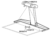
- FIG. 2 is a diagram illustrating an example of the appearance of the image capturing unit 110 on which an original is placed, and is a diagram illustrating a relationship between the main scanning direction, the sub-scanning direction, and the rotation direction by the motor 12.
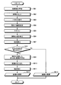
- FIG. 3 is a flowchart showing an example of main processing in the overhead scanner device 100 of the present embodiment.
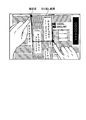
- FIG. 4 is a diagram illustrating an example of two designated points detected on an image and a cutout range based on the two designated points.
- FIG. 1 is a block diagram illustrating an example of the configuration of the overhead scanner device 100.
- FIG. 2 is a diagram illustrating an example of the appearance of the image capturing unit 110 on which an original is placed, and is a diagram illustrating a relationship between the main scanning direction, the sub-scanning direction, and the rotation direction by the motor 12.
- FIG. 3 is a flowchart showing an example of main processing in the overhead scanner
- FIG. 5 is a diagram schematically showing a method for detecting a designated point based on the distance from the center of gravity of the index object on the image to the end by the processing of the designated point detection unit 102b.
- FIG. 6 is a diagram schematically showing a method for detecting a designated point based on the distance from the center of gravity of the index object on the image to the end by the processing of the designated point detection unit 102b.
- FIG. 7 is a flowchart showing an example of a materialization process in the overhead scanner device 100 of the present embodiment.
- FIG. 8 is a diagram schematically illustrating an example of a method for detecting a fingertip by the designated point detection unit 102b.
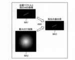
- FIG. 9 is a diagram schematically showing a method of obtaining the fingertip fitness based on the normal vector, the image, and the weighting coefficient.
- FIG. 10 is a diagram showing the center of gravity of the left and right hands, the designated points of the fingertips, and the cutout range detected on the image data.
- FIG. 11 is a diagram schematically showing the region removal process.
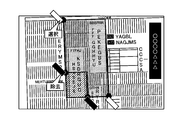
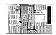
- FIG. 12 is a diagram illustrating an example in which a removal area is designated by a sticky note.
- FIG. 13 is a diagram illustrating an example in which a removal area is designated by a sticky note.
- FIG. 14 is a flowchart illustrating an example of processing during one-handed operation in the overhead scanner device 100 of the present embodiment.
- FIG. 15 is a diagram illustrating a case where the first designated point and the second designated point are detected.
- FIG. 16 is a diagram illustrating a case where the third and fourth designated points are detected.
- FIG. 1 is a block diagram illustrating an example of the configuration of the overhead scanner device 100.
- the overhead scanner device 100 includes at least an image capturing unit 110 that scans a document placed upward from above and a control unit 102.
- the storage unit 106 and an input / output interface are provided.
- the storage unit 106 stores various databases, tables, files, and the like.
- the storage unit 106 is a storage unit, and for example, a memory device such as a RAM / ROM, a fixed disk device such as a hard disk, a flexible disk, an optical disk, or the like can be used.
- the storage unit 106 stores computer programs for giving instructions to a CPU (Central Processing Unit) and performing various processes.
- the storage unit 106 includes a temporary image data file 106a, a processed image data file 106b, and an index object file 106c as shown in the figure.
- the temporary image data file 106a temporarily stores the image data read by the image capturing unit 110.
- the processed image data file 106b stores image data processed by an image cutout unit 102c, an inclination correction unit 102e, and the like described later from the image data read by the image capturing unit 110.
- the input / output interface unit 108 connects the image capturing unit 110, the input device 112, and the output device 114 to the overhead scanner device 100.
- a monitor including a home television
- a speaker or a printer can be used as the output device 114 (hereinafter, the output device 114 may be described as the monitor 114).
- the input device 112 a monitor that realizes a pointing device function in cooperation with a mouse can be used in addition to a keyboard, a mouse, and a microphone.
- a foot switch that can be operated with a foot may be used.
- the image capturing unit 110 scans an original placed upward from above and reads an image of the original.
- the image capturing unit 110 includes a controller 11, a motor 12, an image sensor 13 (for example, an area sensor or a line sensor), and an A / D converter 14.
- the controller 11 controls the motor 12, the image sensor 13, and the A / D converter 14 in response to a command from the control unit 102 via the input / output interface unit 108.
- the image sensor 13 photoelectrically converts light reaching from the line in the main scanning direction of the document into an analog charge amount for each pixel on the line.
- FIG. 2 shows an example of the appearance of the image pickup unit 110 on which the document is placed, and is a diagram showing the relationship among the main scanning direction, the sub-scanning direction, and the rotation direction by the motor 12.
- the image sensor 13 When the image sensor 13 is rotated in the illustrated rotation direction by driving the motor 12, the reading line of the image sensor 13 is moved in the illustrated sub-scanning direction. As a result, the image data of the two-dimensional document is read by the image capturing unit 110.
- the index object file 106c is an index object storage means for storing the color and shape of the index object presented by the user.
- the index object file 106c stores, for each user, the color of the user's hand or finger (skin color), the shape of the protruding end that indicates a point to be specified such as the fingertip of the hand, and the like. Good.
- the index object file 106c may store colors and shapes of sticky notes and pens.
- the index object file 106c includes features (color, shape, etc.) of an index object such as a sticky note and a pen for specifying a cutout range, and an index object such as a sticky note and a pen for specifying an area to be removed from the cutout range. These features (color, shape, etc.) may be stored respectively.
- the control unit 102 includes a CPU that controls the overhead scanner device 100 in an integrated manner.
- the control unit 102 has an internal memory for storing a control program, a program defining various processing procedures, and necessary data, and performs information processing for executing various processes based on these programs.
- the control unit 102 is roughly divided into an image acquisition unit 102a, a designated point detection unit 102b, an image cutout unit 102c, an inclination detection unit 102d, an inclination correction unit 102e, and an index object storage unit 102f.
- the image acquisition unit 102a controls the image capturing unit 110 to acquire an image of a document including at least one index object presented by the user.
- the image acquisition unit 102a controls the controller 11 of the image capturing unit 110 to rotate and drive the motor 12, and is photoelectrically converted by the image sensor 13 and analog / digital converted by the A / D converter 14.
- the image acquisition unit 102a may control the image capturing unit 110 to continuously acquire a two-dimensional image from the image sensor 13 that is an area sensor at predetermined time intervals.
- the image acquisition unit 102a controls the image capturing unit 110 and is presented by the user according to predetermined acquisition triggers (for example, when the finger is stationary, when sound is input / output, or when the foot switch is pressed).
- Two images of a document including one index object may be acquired in time series.
- the image acquisition unit 102a receives one voice image from the input device 112 of the microphone.
- the image acquisition unit 102 a displays an image group continuously acquired by the area sensor.
- One high-definition image by the line sensor may be acquired when the finger is stationary based on the above.
- the designated point detection unit 102b detects two designated points determined based on the distance from the center of gravity of the index object to the end from the image acquired by the image acquisition unit 102a. Specifically, the designated point detection unit 102b determines the distance from the center of gravity of at least one index object on the image to the end based on the image data stored in the image data temporary file 106a by the image acquisition unit 102a. Based on this, a designated point is detected. More specifically, the designated point detection unit 102b may detect, as the designated point, the end (end point) side of a vector whose length is a predetermined length or more with the center point of the index object as the start point and the end as the end point. .
- the designated point detection unit 102b is not limited to detecting two designated points from one image including two index objects, but one point from each of two images including one index object. Two specified points may be detected by detecting the specified points.
- the index object may have, for example, a protruding end portion that points to a point to be specified.
- the index object is an object such as a fingertip of a hand, a sticky note, or a pen that is presented by the user. is there.
- the designated point detection unit 102b detects a skin color partial region from an image based on the image data acquired by the image acquisition unit 102a, and detects an index object such as a fingertip of a hand.
- the designated point detection unit 102b uses a known image based on the color and / or shape stored in the index object file 106c by the index object storage unit 102f from the image based on the image data acquired by the image acquisition unit 102a.
- the index object on the image may be detected by a pattern recognition algorithm or the like.
- the designated point detection unit 102b may detect two points designated by the fingertips of the left and right hands, which are index objects, from an image based on the image data acquired by the image acquisition unit 102a.
- the designated point detection unit 102b creates a plurality of finger direction vectors from the center of gravity of the hand, which is the index object detected as the skin color partial region, to the surroundings, When the overlapping width is closest to a predetermined width, the designated point may be detected using the tip of the finger direction vector as the fingertip. Further, the designated point detection unit 102b may detect two points designated by two sticky notes serving as index objects from the image based on the image data obtained by the image obtaining unit 102a. Further, the designated point detection unit 102b may detect two points designated by two pens serving as index objects from an image based on the image data acquired by the image acquisition unit 102a.
- the image cutout unit 102c cuts out the image acquired by the image acquisition unit 102a in a rectangle having the two points detected by the designated point detection unit 102b as diagonals. Specifically, the image cutout unit 102c sets image data stored in the image data temporary file 106a by the image acquisition unit 102a, using a rectangle with two points detected by the designated point detection unit 102b as a cutout range. The image data of the cutout range is acquired from the image data, and the processed image data cut out is stored in the processed image data file 106b.
- the image cutout unit 102c forms a rectangle composed of lines that are diagonally set to the two detected points and parallel to the document edge in accordance with the document inclination detected by the inclination detection unit 102d.
- the cutout range may be used. That is, when the document is tilted, it is considered that the characters and figures described in the document are also tilted. Therefore, the image cutout unit 102c is tilted according to the tilt of the document detected by the tilt detection unit 102d. A rectangle may be used as the cutout range.
- the inclination detection unit 102d detects the inclination of the document from the image acquired by the image acquisition unit 102a. Specifically, the inclination detection unit 102d detects the document edge by detecting the document edge or the like based on the image data stored in the image data temporary file 106a by the image acquisition unit 102a.
- the inclination correction unit 102e corrects the inclination of the image cut out by the image cutout unit 102c with the inclination detected by the inclination detection unit 102d. Specifically, the inclination correction unit 102e rotates the image cut out according to the inclination detected by the inclination detection unit 102d by the image cutout unit 102c so that the inclination is eliminated. For example, when the inclination detected by the inclination detection unit 102d is ⁇ °, the image cut out by the image cutout unit 102c is rotated by ⁇ ° to generate image data with the inclination corrected, and the processed image Store in the data file 106b.
- the index object storage unit 102f stores the color and / or shape of the index object presented by the user in the index object file 106c. For example, the index object storage unit 102f learns the color and / or shape of the index object from the image of the index object that does not include a document acquired by the image acquisition unit 102a by a known learning algorithm, and the color of the learning result And the shape may be stored in the index object file 106c.
- the removed image acquisition unit 102g acquires an image of a document including an index object presented by the user inside a rectangle whose diagonals are two specified points detected by the specified point detection unit 102b. Means.
- the removed image acquisition unit 102g may acquire the image of the document by controlling the image capturing unit 110 in the same manner as the image acquisition unit 102a described above.
- the removed image acquisition unit 102g controls the image capturing unit 110 to acquire an image at a predetermined acquisition opportunity (for example, when a finger is stationary, when sound is input / output, or when a foot switch is pressed). Good.
- the removal area detection unit 102h is a removal area detection unit that detects an area designated by the index object from the image acquired by the removal image acquisition unit 102g.
- the removal area detection unit 102h may detect an area specified by the index object (such as a rectangle having two points as a diagonal) as the “area specified by the index object”.
- the removal area detection unit 102h determines a point where two lines that divide the rectangle into four at one point designated by the user intersect among the rectangles whose diagonals are the two designated points. Further, one area among the four-divided areas at one point designated by the user may be detected as “area designated by the index object”.
- the removal region detection unit 102h may detect a point designated by the index object in the same manner as the above-described process in which the designated point detection unit 102b detects the designated point.
- the region removal unit 102j is a region removal unit that removes the region detected by the removal region detection unit 102h from the image cut out by the image cutout unit 102c.
- the area removing unit 102j may remove the area from the cutout range before cutting out by the image cutting out part 102c, or may remove the area from the cut out image after cutting out by the image cutting out part 102c. Also good.
- FIG. 3 is a flowchart showing an example of main processing in the overhead scanner device 100 of the present embodiment.
- the image acquisition unit 102a controls the image capturing unit 110 to acquire an image of a document including at least one index object presented by the user, and obtains image data of the image.
- the image data is stored in the temporary image data file 106a (step SA1).
- the image acquisition unit 102a controls the image capturing unit 110 and is presented by the user according to predetermined acquisition triggers (for example, when the finger is stationary, when sound is input / output, or when the foot switch is pressed).
- Two images of a document including one index object may be acquired.
- the index object may have, for example, a protruding end portion that points to a point to be specified, and may be an object such as a fingertip of a hand, a sticky note, or a pen that is presented by the user.
- the designated point detection unit 102b is based on the image data stored in the image data temporary file 106a by the image acquisition unit 102a, and is determined based on the distance from the center of gravity of the index object to the end on the image.
- the designated point is detected (step SA2). More specifically, the designated point detection unit 102b detects a designated point on the end (end point) side for a vector whose length is a predetermined length or more with the center of the index object as the start point and the end as the end point. Also good.
- the designated point detection unit 102b is not limited to detecting two designated points from one image including two index objects, but one point from each of two images including one index object. Two specified points may be detected by detecting the specified points.
- the designated point detection unit 102b may identify the range of the index object on the image from the image based on the image data by color, shape, or the like, and detect the two designated points indicated by the identified index object.
- FIG. 4 is a diagram illustrating an example of two designated points detected on an image and a cutout range based on the two designated points.
- FIG. 4 when two diagonal points in a range that the user wants to cut out are designated by a user using a finger as an index object on a manuscript such as a newspaper, the designated point detection unit 102b A skin-colored partial region may be detected from an image based on the image data to detect a fingertip of a hand serving as an index object, and two specified points specified by the fingertips of the left and right hands may be detected.
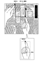
- FIG. 5 and FIG. 6 are diagrams schematically showing a method of detecting a designated point based on the distance from the center of gravity of the index object on the image to the end by the processing of the designated point detection unit 102b. .
- the designated point detection unit 102b detects an index object on the image based on the feature of the index object stored in the index object file 106c, and uses the center of gravity of the detected index object as a starting point to end the end part.
- a designated point may be detected on the end (end point) side of the vector. That is, the designated point is detected based on the distance with the line segment from the center of gravity to the end as a vector in the fingertip direction.
- the direction indicated by the finger and the fingertip are recognized as vectors, so that the designated point can be detected as intended by the user regardless of the angle of the fingertip.
- the designated point Since the designated point is detected based on the distance from the center of gravity to the end, the designated point does not have to be inside each index object as shown in FIGS. That is, as shown in FIG. 6, even when the point intended by the user is not at the leftmost end of the hand range and the fingertip is directed directly above, the designated point detection unit 102b can move from the center of gravity to the end. The designated point can be accurately detected based on the distance (for example, by determining whether or not there is a predetermined length or more).
- the overhead scanner device 100 is disposed so as to face the user, and the document is disposed between them. Therefore, the angle at which the user points to the document is limited due to the layout relationship.
- the designated point detection unit 102b improves detection accuracy by not detecting a designated point as a false detection of a vector in a predetermined direction (for example, an unnatural downward vector). You may plan.
- FIGS. 4 to 6 show an example in which two designated points are designated at the same time using both hands.
- the designated point detection unit 102b may detect two designated points designated by the respective index objects from the two acquired images.
- the detection of one designated point with one index object has been described, the present invention is not limited to this, and two or more designated points may be detected from one index object.
- the user may indicate two designated points that are opposite to the cutout region using two fingers such as a thumb and an index finger at the same time.
- the designated point detection unit 102b makes it unnatural that one index object includes a predetermined number (for example, three) or more vectors, and excludes index objects in which a predetermined number or more of vectors are detected. The detection accuracy may be increased.
- the index object is not limited to the fingertip of the hand, and the specified point detection unit 102b may detect two specified points specified by two sticky notes as the index object from the image based on the image data. Further, the designated point detection unit 102b may detect two designated points designated by two pens serving as index objects from an image based on the image data.
- the image cutout unit 102c creates a cutout range as a rectangle with the two designated points detected by the designated point detection unit 102b as diagonals (step SA3).
- a rectangle having two specified points as diagonals is a quadrangle such as a rectangle or a square formed by lines parallel to the reading area of the image capturing unit 110 and the document edge. There may be.
- the image cutout unit 102c extracts the image data in the cutout range from the image data stored in the image data temporary file 106a by the image acquisition unit 102a, and stores it in the processed image data file 106b (step SA4).
- the image cutout unit 102c may output the cutout image data to the output device 114 such as a monitor.
- the above is an example of the main processing in the overhead scanner device 100 of the present embodiment.
- FIG. 7 is a flowchart showing an example of a materialization process in the overhead scanner device 100 of the present embodiment.
- the index object storage unit 102f learns the color and / or shape of the index object presented by the user (step SB1). For example, the index object storage unit 102f learns the color and / or shape of the index object from the image of the index object that does not include a document acquired by the image acquisition unit 102a by a known learning algorithm, and the color of the learning result And the shape are stored in the index object file 106c.
- the image acquisition unit 102a causes the image capturing unit 110 to scan and acquire an image in advance (before steps SB2 to SB5, which will be described later), and scans only the index object (not including the original).
- the unit 102f may store the attribute (color, shape, etc.) of the index object in the index object file 106c based on the image acquired by the image acquisition unit 102a. For example, when the index object is a finger or a tag, the index object storage unit 102f may read the color of the finger (skin color) or the color of the sticky note from the image including the index object and store it in the index object file 106c. .
- the index object storage unit 102f is not limited to reading the color of the index object based on the image acquired by the image acquisition unit 102a, but may allow the user to specify the color via the input device 112.
- the index object storage unit 102f may extract the shape of the pen from the image acquired by the image acquisition unit 102a and store it in the index object file 106c.
- the shape stored in the index object file 106c is used for the designated point detection unit 102b to search for the index object (pattern matching).
- the image acquisition unit 102a issues a trigger for starting reading by the image capturing unit 110 (step SB3).
- the image acquisition unit 102a may start reading after a predetermined time has elapsed using an interval timer based on an internal clock of the control unit 102.
- the user designates the clipping range using both hands, so that the image acquisition unit 102a immediately follows the input of the reading start via the input device 112 by the user.
- a trigger using an interval timer or the like is issued.
- a trigger for starting reading may be issued at a predetermined acquisition timing such as when a finger is stationary, when sound is input / output, or when a foot switch is pressed.
- the image acquisition unit 102a controls the image capturing unit 110 at a timing according to the issued trigger, and both hands presented by the user.
- the image of the original including the fingertip is scanned, and the image data is stored in the image data temporary file 106a (step SB5).
- the inclination detection unit 102d detects the document edge and the like from the image based on the image data stored in the image data temporary file 106a by the image acquisition unit 102a (step SB6).
- the designated point detection unit 102b uses the learning result color (skin color) stored in the index object file 106c by the index object storage unit 102f from the image based on the image data stored in the image data temporary file 106a by the image acquisition unit 102a. ) And the shape, etc., an index object such as a fingertip of a hand is detected by a known pattern recognition algorithm or the like, and two designated points designated by the fingertips of both hands are detected (step SB7).
- the designated point detection unit 102b creates a plurality of finger direction vectors from the center of gravity of the hand, which is an index object detected as a skin color partial region, toward the periphery, and the normal vector of the finger direction vector
- the designated point may be detected using the tip of the finger direction vector as the fingertip.
- FIG. 8 is a diagram schematically illustrating an example of a method of detecting the fingertip by the designated point detection unit 102b.
- the designated point detection unit 102b extracts only the flesh color hue from the color image data stored in the image data temporary file 106a by the image acquisition unit 102a by color space conversion.
- a white area represents a skin color partial area in the color image
- a black area represents an area other than the skin color in the color image.
- the designated point detection unit 102b obtains the center of gravity of the extracted skin color partial area and determines the range of the right hand and the left hand, respectively.
- a range indicated as “hand range” indicates a partial region of the right hand.
- the designated point detection unit 102b sets a search point in a line that is a certain distance (offset amount) from above the determined hand range. That is, there is a possibility that there is a non-skin color nail in a certain range from the fingertip to the center of gravity of the hand, and in order to avoid a decrease in detection accuracy due to this nail, the designated point detection unit 102b An offset is provided to detect the fingertip.
- the designated point detection unit 102b calculates a finger direction vector from the center of gravity to the search point. That is, since the finger extends from the center of gravity of the hand and protrudes toward the outer periphery of the hand, a finger direction vector is first obtained in order to search for the finger. 8 represents a finger direction vector passing through one search point at the left end, the designated point detection unit 102b obtains a finger direction vector for each search point.
- FIG. 9 is a diagram schematically showing a method of obtaining the fingertip fitness based on the normal vector, the image, and the weighting coefficient.
- the designated point detection unit 102b superimposes the normal vector and the skin color binarized image (for example, an image in which the skin color partial area in FIG. 8 is white) to calculate an AND image.
- the AND image shows a region (overlap width) where the line segment of the normal vector and the skin color partial region overlap, and this represents the thickness of the finger. .
- the designated point detection unit 102b multiplies the AND image by a weighting coefficient to calculate the fingertip fitness.
- the lower left diagram MA2 of FIG. 9 is a diagram schematically showing the weighting coefficients. As described above, the weighting coefficient is a coefficient that increases as it becomes the center, and is set so that the degree of fitness increases when the center of the fingertip is captured.
- a right diagram MA3 in FIG. 9 is an AND image of an AND image and an image of a weighting coefficient, and the degree of fitness increases as the center of the line segment is increased. In this way, by using the weighting factor, the candidate having the center of the fingertip is calculated so that the fitness is higher.
- the designated point detection unit 102b obtains the degree of fitness for the normal vector of each search point, determines the position where the fingertip has the highest degree of fitness, and sets it as the designated point.
- FIG. 10 shows the center of gravity of the left and right hands (two points indicated as “left” and “right” in the figure) detected on the image data, and the designated point of the fingertip (the fingertip in the figure). It is a figure which shows two cutout circles) and a cutting-out range (rectangle in a figure).
- the designated point detection unit 102b obtains two designated points designated by the fingertip from the center of gravity of the left and right hands.
- the image cutout unit 102c sets the two designated points detected.
- a rectangle reflecting the inclination detected by the inclination detecting unit 102d is created as a cutout region (step SB9).
- the image cutout unit 102c sets a rectangle inclined by ⁇ ° with two detected specified points as diagonals as a cutout region.
- the image cutout unit 102c cuts out the image in the created cutout range from the image data stored in the image data temporary file 106a by the image acquisition unit 102a (step SB10).
- the control unit 102 of the overhead scanner device 100 may perform an area removal process for removing an area from the cutout range.
- FIG. 11 is a diagram schematically showing the region removal processing.
- the removed image acquisition unit 102g performs the designated inspection as shown in the lower diagram of FIG. An image of a document including an index object presented by the user is acquired inside a rectangle whose diagonals are two designated points detected by the output unit 102b. Then, the removal area detection unit 102h detects the area designated by the index object (rectangular area having two points diagonally indicated by diagonal lines in the figure) from the image acquired by the removal image acquisition unit 102g. Finally, the region removing unit 102j removes the region detected by the removal region detecting unit 102h from the image cut out by the image cutout unit 102c.
- these area removal processes may be performed before being cut out by the image cutout unit 102c or after being cut out by the image cutout unit 102c. Further, when the same index object is used, it is necessary to determine whether the user has designated a cutout range or an area to be removed from the cutout range. As an example, as shown in FIG. 11, when specifying the cutout range, specify the upper left and lower right two points, while when specifying the area to be removed from the cutout range, specify the upper right and lower left points. By doing so, both may be made identifiable. In addition, it may be identified by the state (color, shape, etc.) of the index object. For example, when specifying the clipping range, the index finger is used for specifying, while the area to be removed from the clipping range is specified by the thumb. Both may be made identifiable by designating using.
- the inclination correction unit 102e corrects the inclination of the image cut out by the image cutout unit 102c with the inclination detected by the inclination detection unit 102d (step SB11). For example, when the inclination detected by the inclination detection unit 102d is ⁇ ° as described above, the inclination correction unit 102e rotates the image cut out by the image cutout unit 102c by ⁇ ° so that the inclination is eliminated. Correct the tilt.
- the inclination correcting unit 102e stores the processed image data after the inclination correction in the processed image data file 106b (step SB12).
- the image acquisition unit 102a stores the image data in the temporary image data file 106a.
- the processed image data is stored in the processed image data file 106b as it is (step SB13).
- the index object storage unit 102f learns the color and shape of the index object by scanning in advance a tag or pen that is used as an index object by the processing of the image acquisition unit 102a.
- the index object storage unit 102f stores the learned characteristic of the index object in the index object file 106c.
- the index object storage unit 102f has features (color, shape, and the like) of an index object such as a tag and a pen for specifying a clipping range, and an index such as a tag and a pen for specifying an area to be removed from the clipping range.
- the feature of the object may be learned and stored so as to be identifiable.
- an image is acquired.
- the image acquisition unit 102a controls the image capturing unit 110 to image the document including the index object. To get.
- the position of the index object is searched.
- the designated point detection unit 102b detects the index object from the acquired image based on the characteristics (color, shape, etc.) of the index object stored in the index object file 106c. In this way, the position of the tag or pen is searched based on the learned feature.
- a designated point is detected.
- the designated point detection unit 102b detects two designated points determined based on the distance from the center of gravity of the detected index object to the end. Note that an end point with respect to the center of gravity of a sticky note and a pen may appear at both ends. For this reason, the designated point detection unit 102b uses, as an index, a vector that approaches the center of gravity of the other index object and / or is close to the center of gravity of the other index object among the two vectors obtained from both ends of the one index object. The object may be detected.
- a sticky note or a pen may be used to specify an area to be removed from the cutout range.
- the same index object such as a sticky note or a pen
- a sticky index object is used, and when a cutout range is designated, two points are designated using a white sticky note paper, and removed from the cutout range.
- two points may be designated by specifying two points with black sticky notes.
- the identification is not limited to the color difference, and may be performed based on the shape of the index object. That is, as shown in FIG. 13, when specifying a clipping range, two points are specified using a rectangular sticky note, while when specifying an area to be removed from the clipping range, a triangular sticky note is used. By designating two points, the two may be identified.
- the area removal process is executed by the index object storage unit 102f, the removed image acquisition unit 102g, and the removal area detection unit 102h as described above.
- FIG. 14 is a flowchart showing an example of processing during one-handed operation in the overhead scanner device 100 of the present embodiment.
- the index object storage unit 102f learns the color and / or shape of the index object presented by the user, similarly to step SB1 described above (step SC1).
- the image acquisition unit 102a controls the image capturing unit 110 to continuously acquire two-dimensional images at predetermined time intervals from the image sensor 13 of the area sensor, and starts monitoring the fingertip that is the index object. (Step SC2).
- the image acquisition unit 102a detects the fingertip of the user's hand, which is an index object, from the image by the area sensor (step SC4). ).
- the image acquisition unit 102a determines whether or not it is a predetermined acquisition opportunity for acquiring an image.
- the predetermined acquisition opportunity is when the finger is stationary, when sound is input / output, when the foot switch is pressed, or the like.
- the image acquisition unit 102a may determine whether the fingertip has stopped based on a group of images continuously obtained from the area sensor.
- the predetermined acquisition trigger is when the confirmation sound is output
- the image acquisition unit 102a determines that the predetermined time has elapsed from the time when the fingertip of the hand is detected (step SC4), based on the internal clock. It may be determined whether a confirmation sound is output from 114.
- the predetermined acquisition trigger is when the foot switch is pressed, the image acquisition unit 102a may determine whether or not a pressing signal is obtained from the input device 112 of the foot switch.
- step SC5 If the image acquisition unit 102a determines that it is not a predetermined acquisition opportunity (step SC5, No), the process returns to step SC4 and continues to monitor the fingertip.
- the image acquisition unit 110 such as a line sensor is controlled to include the fingertip of one hand presented by the user.
- the image data including the designated point by the fingertip is scanned and stored in the temporary image data file 106a (step SC6).
- the specified point detection unit 102b or the removal area detection unit 102h is not limited to storing the image data, and the specified point detection unit 102b or the removal region detection unit 102h only specifies the specified point by the detected index object (for example, the specified point on the end side of the vector starting from the center of gravity) May be saved.
- FIG. 15 is a diagram illustrating a case where the first and second designated points are detected.
- FIG. 16 is a diagram illustrating a case where the third and fourth designated points are detected.
- the removal area detection unit 102 h performs processing within the rectangular cutout range having the two specified points as diagonals.
- the designated point of the third fingertip is detected.
- the cutout range can be divided into four areas as shown in the figure, but in order to select which of these four areas is the removal area, the user can select Further, the inside of the four areas is indicated with the fingertip. That is, as shown in the lower diagram of FIG. 16, in the fourth image captured in the repetitive process, the fourth designated point is detected by the process of the removal area detection unit 102h.
- the region removing unit 102j can determine a region to be removed from the cut-out range (region indicated by hatching in the drawing) among the four regions.
- the inclination detection unit 102d uses the image based on the image data stored in the image data temporary file 106a by the image acquisition unit 102a. Then, the original edge is detected to detect the inclination of the original, and the image cutout unit 102c cuts out a rectangle reflecting the inclination detected by the inclination detection unit 102d with the two designated points detected as diagonals. An area is created (step SC8). When there is a removal area, the image cutout unit 102c may create a cutout range after the area removal by the area removal unit 102j, or from an image cut out by the following processing of the image cutout unit 102c. The area removal unit 102j may remove the image of the removal area.
- the image cutout unit 102c cuts out the image in the created cutout range from the image data stored in the image data temporary file 106a by the image acquisition unit 102a (step SC9).
- the range to be cut out of the document may be covered by the index object, but the entire range of the cut-out range may be captured as shown in the lower diagram of FIG. 15.
- the image cutout unit 102c determines image data that does not include the index object in the cutout range, and performs cutout processing on the image data. In this way, the user does not need to arrange the indicator so as to intentionally avoid the document, so that more natural operability can be provided.
- the image cutout unit 102c may acquire a cutout range image by combining a plurality of images, or the user may copy the original.
- the image acquisition unit 102a may be made to acquire an image of a document that does not include the index object after waiting for the index object to be removed from the image.
- the tilt correction unit 102e corrects the tilt of the image cut out by the image cutout unit 102c with the tilt detected by the tilt detection unit 102d, similarly to step SB11 described above (step SC10).
- the tilt correction unit 102e rotates the image cut out by the image cutout unit 102c by ⁇ ° so that the inclination is eliminated. Correct the tilt.
- the inclination correction unit 102e stores the processed image data after the inclination correction in the processed image data file 106b (step SC11).
- the above is an example of processing during one-handed operation in the overhead scanner device 100 of the present embodiment.
- the image acquisition by the removed image acquisition unit 102g has been described without distinction as the image acquisition by the image acquisition unit 102a.
- the part described as the process of the image acquisition unit 102a is as follows. Strictly, it is executed as a process of the removed image acquisition unit 102g.
- the overhead scanner device 100 controls the image capturing unit 110 to acquire an image of a document including at least one index object presented by the user, and from the acquired image, Two designated points determined based on the distance from the center of gravity of the index object to the end are detected, and the acquired image is cut out in a rectangle with the two designated points detected as diagonals.
- the operability of specifying the cutout range can be improved without requiring a special tool such as a console or a dedicated pen for operating the cursor movement button on the display screen.
- the cutout range can be designated without removing it and without smearing the original with a dedicated pen or the like. Further, since the designated point is detected based on the distance indicated by the vector from the center of gravity of the index object to the end, the designated point intended by the user can be accurately detected.
- the finger has been developed to be removed because it is not desired to be copied.
- the image is captured by actively capturing an object such as a finger together with the document. It is used for image control or image control. That is, such an object such as a finger could not be read by a flatbed type scanner or an ADF (Auto Document Feeder) type scanner, but according to the present embodiment, an overhead type scanner is used actively.
- the object image can be used for detection of the cutout range.
- the overhead scanner device 100 controls the image capturing unit 110 to acquire two images of a document including one index object presented by the user according to a predetermined acquisition opportunity. Then, two points designated by the index object are detected from the two acquired images.
- the user can specify the cutout range using only a single index object, and in particular, when using the fingertip as the index object, the user can specify the cutout range by an operation with only one hand. It becomes possible.
- the overhead scanner device 100 acquires and acquires an image of a document including an index object presented by a user inside a rectangle whose diagonals are two detected points. An area designated by the index object is detected from the image, and the detected area is removed from the cut image.
- the range to be cut out with a complex polygon such as a block shape in which a plurality of rectangles are combined, can be specified.
- the overhead scanner device 100 detects a skin color partial region from the acquired image, detects a fingertip of a hand as an index object, and specifies two designated points designated by the fingertip of the hand. Is detected. Accordingly, it is possible to accurately detect the finger region on the image based on the skin color, and to accurately detect the designated clipping range.
- the overhead scanner device 100 creates a plurality of finger direction vectors from the center of gravity of the hand to the periphery, and the fitness indicated by the overlapping width of the partial areas with the normal vector of the finger direction vector Is the highest, let the tip of the finger direction vector be the fingertip.
- the fingertip can be accurately detected based on the assumption that the finger protrudes from the center of gravity of the hand toward the outer periphery of the hand.
- the overhead scanner device 100 detects two designated points designated by two sticky notes as index objects from the acquired image. As a result, a rectangle whose diagonals are two designated points designated by two sticky notes can be detected as a cutout range.
- the overhead scanner device 100 detects two designated points designated by two pens serving as index objects from the acquired image. As a result, a rectangle whose diagonals are two designated points designated by two pens can be detected as a cutout range.
- the overhead scanner device 100 stores the color and / or shape of the index object presented by the user in the storage unit, and stores the color and / or shape stored from the acquired image. Based on the above, an index object on the image is detected, and two designated points designated by the index object are detected. Thus, even if the color or shape of the index object (for example, the fingertip of the hand) is different for each user, the index object on the image can be accurately obtained by learning the color or shape of the index object. A cutout range can be detected by detecting a region.
- the overhead scanner device 100 detects the inclination of the document from the acquired image, cuts out the image in the cut-out range reflecting the inclination, rotates the cut-out image so that the inclination is eliminated, and sets the inclination. to correct.
- the processing speed can be improved and waste of resources can be eliminated.
- the present invention may be implemented in various different embodiments other than the above-described embodiments within the scope of the technical idea described in the claims.
- the index object may be composed of a combination of two or more of a fingertip, a pen, a sticky note, and the like of the user's hand. Good.
- processing is performed in response to a request from a client terminal in a separate housing from the overhead scanner device 100, and the processing result is You may make it return to a client terminal.
- all or a part of the processes described as being automatically performed can be manually performed, or all of the processes described as being manually performed can be performed. Alternatively, a part can be automatically performed by a known method.
- the processing procedures, control procedures, specific names, information including registration data for each processing, screen examples, and database configuration shown in the above documents and drawings may be arbitrarily changed unless otherwise specified. Can do.
- each illustrated component is functionally conceptual and does not necessarily need to be physically configured as illustrated.
- the processing functions provided in each device of the overhead scanner device 100 are interpreted or executed by a CPU (Central Processing Unit) and the CPU. It may be realized by a program to be executed, or may be realized as hardware by wired logic.
- the program is recorded on a recording medium to be described later, and is mechanically read by the overhead scanner device 100 as necessary. That is, a computer program for performing various processes is recorded in the storage unit 106 such as a ROM or an HD. This computer program is executed by being loaded into the RAM, and constitutes a control unit in cooperation with the CPU.
- the computer program may be stored in an application program server connected to the overhead scanner device 100 via an arbitrary network, and may be downloaded in whole or in part as necessary. is there.
- the program according to the present invention may be stored in a computer-readable recording medium, or may be configured as a program product.
- the “recording medium” is any memory card, USB memory, SD card, flexible disk, magneto-optical disk, ROM, EPROM, EEPROM, CD-ROM, MO, DVD, Blu-ray Disc, etc.
- the “program” is a data processing method described in an arbitrary language or description method, and may be in any format such as source code or binary code. Note that the “program” is not necessarily limited to a single configuration, but is distributed in the form of a plurality of modules and libraries, or in cooperation with a separate program typified by an OS (Operating System). Including those that achieve the function.
- OS Operating System
- a well-known structure and procedure can be used about the specific structure for reading a recording medium in each apparatus shown in embodiment, a reading procedure, or the installation procedure after reading.
- Various databases and the like (image data temporary file 106a, processed image data file 106b, and index object file 106c) stored in the storage unit 106 are a memory device such as a RAM and a ROM, a fixed disk device such as a hard disk, a flexible disk,
- the storage means such as an optical disk stores various programs, tables, databases, and the like used for various processes.
- the overhead scanner device 100 may be configured as an information processing device such as a known personal computer or workstation, or may be configured by connecting an arbitrary peripheral device to the information processing device. Further, the overhead scanner device 100 may be realized by installing software (including programs, data, and the like) that causes the information processing device to realize the method of the present invention. Furthermore, the specific form of distribution / integration of the devices is not limited to that shown in the figure, and all or a part of them may be functional or physical in arbitrary units according to various additions or according to functional loads. Can be distributed and integrated. That is, the above-described embodiments may be arbitrarily combined and may be selectively implemented.
- the overhead scanner device, the image processing method, and the program according to the present invention can be implemented in many industrial fields, particularly in the image processing field that handles images read by a scanner, and are extremely useful. is there.
Landscapes
- Engineering & Computer Science (AREA)
- Physics & Mathematics (AREA)
- General Physics & Mathematics (AREA)
- Theoretical Computer Science (AREA)
- Multimedia (AREA)
- Signal Processing (AREA)
- Image Input (AREA)
- Studio Devices (AREA)
- Position Input By Displaying (AREA)
- Facsimile Scanning Arrangements (AREA)
Abstract
Description
本実施形態に係るオーバーヘッドスキャナ装置100の構成について図1を参照して説明する。図1は、オーバーヘッドスキャナ装置100の構成の一例を示すブロック図である。
上述した構成のオーバーヘッドスキャナ装置100で実行される処理の一例について、図3~図16を参照して説明する。
本実施形態のオーバーヘッドスキャナ装置100におけるメイン処理の一例について図3~図6を参照して説明する。図3は、本実施形態のオーバーヘッドスキャナ装置100におけるメイン処理の一例を示すフローチャートである。
つづいて、上述したメイン処理において、指標物の学習処理や傾き補正処理等を更に含む具体化処理の一例について図7~図11を参照して説明する。図7は、本実施形態のオーバーヘッドスキャナ装置100における具体化処理の一例を示すフローチャートである。
上述した具体化処理では、利用者により両手の指先によって指定点が指定された例について説明したが、これに限られず、付箋やペンにより指定点が指定されてもよい。なお、指先と同様に、付箋やペンについても方向ベクトルにより指定点を決定することができるが、付箋やペンは色や形状が一様ではないので、以下に示すように、指先による指定点の検出とは異なるアルゴリズムを用いてもよい。
上述した例2-1ないし2-3では、両手や2枚以上の付箋など2つの指標物を同時に用いて切り出し範囲や除去領域を指定する例について説明したが、以下に示すように、片手等を用いて1つの指標物で切り出し範囲や除去領域を指定してもよい。ここで、図14は、本実施形態のオーバーヘッドスキャナ装置100における片手操作時の処理の一例を示すフローチャートである。
以上、本実施形態によれば、オーバーヘッドスキャナ装置100は、画像撮像部110を制御して、利用者により提示された少なくとも1つの指標物を含む原稿の画像を取得し、取得された画像から、指標物の重心から端部までの距離に基づいて決定された2点の指定点を検出し、検出された2つの指定点を対角とする矩形で、取得された画像を切り出す。これにより、表示画面上でカーソル移動ボタンを操作するコンソールや専用ペン等の特別なツールを必要とすることなく、切り出し範囲指定の操作性を向上させることができる。例えば、従来、利用者は、原稿とスキャナ装置から一旦視線を外して表示画面のコンソールをみるため作業が中断され生産効率の低下を招いていたが、本発明では、原稿とスキャナ装置から視線を外すことなく、また、専用ペン等で原稿を汚すことなく、切り出し範囲を指定することができる。また、指標物の重心から端部までのベクトルが示す距離に基づいて指定点を検出するので、利用者が意図した指定点を正確に検出することができる。
102 制御部
102a 画像取得部
102b 指定点検出部
102c 画像切出部
102d 傾き検出部
102e 傾き補正部
102f 指標物格納部
102g 除去画像取得部
102h 除去領域検出部
102j 領域除去部
106 記憶部
106a 画像データ一時ファイル
106b 加工画像データファイル
106c 指標物ファイル
108 入出力インターフェース部
112 入力装置
114 出力装置
Claims (11)
- 画像撮像部と制御部とを備え、
前記制御部は、
前記画像撮像部を制御して、利用者により提示された少なくとも1つの指標物を含む原稿の画像を取得する画像取得手段と、
前記画像取得手段により取得された前記画像から、前記指標物の重心から端部までの距離に基づいて決定された2点の指定点を検出する指定点検出手段と、
前記指定点検出手段により検出された前記2点を対角とする矩形で、前記画像取得手段により取得された前記画像を切り出す画像切出手段と、
を備えたことを特徴とするオーバーヘッドスキャナ装置。 - 前記画像取得手段は、前記画像撮像部を制御して、予め定めた取得契機に従って、利用者により提示された1つの指標物を含む原稿の画像を、2枚取得し、
前記指定点検出手段は、前記画像取得手段により取得された2枚の前記画像から、前記指標物で指定された前記2点を検出することを特徴とする請求項1に記載のオーバーヘッドスキャナ装置。 - 前記制御部は、
前記指定点検出手段により検出された前記2点を対角とする前記矩形の内部に、前記利用者により提示された前記指標物を含む前記原稿の画像を取得する除去画像取得手段と、
前記除去画像取得手段により取得された前記画像から、前記指標物で指定された領域を検出する除去領域検出手段と、
前記除去領域検出手段により検出された前記領域を、前記画像切出手段により切り出された前記画像から除去する領域除去手段と、
を更に備えたことを特徴とする請求項1または2に記載のオーバーヘッドスキャナ装置。 - 前記指標物は、利用者の手の指先であり、
前記指定点検出手段は、
前記画像取得手段により取得された前記画像から肌色の部分領域を検出して前記指標物となる前記手の指先を検出し、当該指標物で指定された2点を検出することを特徴とする請求項1乃至3のいずれか1項に記載のオーバーヘッドスキャナ装置。 - 前記指定点検出手段は、
前記手の重心から周囲に向けて複数の指方向ベクトルを作成し、前記指方向ベクトルの法線ベクトルとの前記部分領域の重なり幅が所定の幅に最も近い場合に、当該指方向ベクトルの先端を前記指先とすることを特徴とする請求項4に記載のオーバーヘッドスキャナ装置。 - 前記指標物は、付箋であり、
前記指定点検出手段は、
前記画像取得手段により取得された前記画像から、前記指標物となる2枚の前記付箋で指定された2点を検出することを特徴とする請求項1乃至3のいずれか1項に記載のオーバーヘッドスキャナ装置。 - 前記指標物は、ペンであり、
前記指定点検出手段は、
前記画像取得手段により取得された前記画像から、前記指標物となる2本の前記ペンで指定された2点を検出することを特徴とする請求項1乃至3のいずれか1項に記載のオーバーヘッドスキャナ装置。 - 更に、記憶部を備え、
前記制御部は、
利用者により提示される前記指標物の色および/または形を前記記憶部に格納する指標物格納手段、
を更に備え、
前記指定点検出手段は、
前記画像取得手段により取得された前記画像から、前記指標物格納手段により前記記憶部に格納された前記色および/または前記形に基づいて当該画像上の前記指標物を検出し、当該指標物で指定された2点を検出することを特徴とする請求項1に記載のオーバーヘッドスキャナ装置。 - 前記制御部は、
前記画像取得手段により取得された前記画像から、前記原稿の傾きを検出する傾き検出手段と、
前記画像切出手段により切り出された前記画像を、前記傾き検出手段により検出された前記傾きで傾き補正する傾き補正手段と、
を更に備えたことを特徴とする請求項1に記載のオーバーヘッドスキャナ装置。 - 画像撮像部と制御部とを備え、オーバーヘッドスキャナ装置の前記制御部で実行される、
前記画像撮像部を制御して、利用者により提示された少なくとも1つの指標物を含む原稿の画像を取得する画像取得ステップと、
前記画像取得ステップにて取得された前記画像から、前記指標物の重心から端部までの距離に基づいて決定された2点の指定点を検出する指定点検出ステップと、
前記指定点検出ステップにて検出された前記2点を対角とする矩形で、前記画像取得ステップにて取得された前記画像を切り出す画像切出ステップと、
を含むことを特徴とする画像処理方法。 - 画像撮像部と制御部とを備え、オーバーヘッドスキャナ装置の前記制御部に実行させるための、
前記画像撮像部を制御して、利用者により提示された少なくとも1つの指標物を含む原稿の画像を取得する画像取得ステップと、
前記画像取得ステップにて取得された前記画像から、前記指標物の重心から端部までの距離に基づいて決定された2点の指定点を検出する指定点検出ステップと、
前記指定点検出ステップにて検出された前記2点を対角とする矩形で、前記画像取得ステップにて取得された前記画像を切り出す画像切出ステップと、
を含むプログラム。
Priority Applications (3)
| Application Number | Priority Date | Filing Date | Title |
|---|---|---|---|
| JP2012518299A JP5364845B2 (ja) | 2010-05-31 | 2011-04-28 | オーバーヘッドスキャナ装置、画像処理方法、および、プログラム |
| CN201180026485.6A CN102918828B (zh) | 2010-05-31 | 2011-04-28 | 上置型扫描仪装置及图像处理方法 |
| US13/689,228 US20130083176A1 (en) | 2010-05-31 | 2012-11-29 | Overhead scanner device, image processing method, and computer-readable recording medium |
Applications Claiming Priority (2)
| Application Number | Priority Date | Filing Date | Title |
|---|---|---|---|
| JP2010-125150 | 2010-05-31 | ||
| JP2010125150 | 2010-05-31 |
Related Child Applications (1)
| Application Number | Title | Priority Date | Filing Date |
|---|---|---|---|
| US13/689,228 Continuation US20130083176A1 (en) | 2010-05-31 | 2012-11-29 | Overhead scanner device, image processing method, and computer-readable recording medium |
Publications (1)
| Publication Number | Publication Date |
|---|---|
| WO2011152166A1 true WO2011152166A1 (ja) | 2011-12-08 |
Family
ID=45066548
Family Applications (1)
| Application Number | Title | Priority Date | Filing Date |
|---|---|---|---|
| PCT/JP2011/060484 Ceased WO2011152166A1 (ja) | 2010-05-31 | 2011-04-28 | オーバーヘッドスキャナ装置、画像処理方法、および、プログラム |
Country Status (4)
| Country | Link |
|---|---|
| US (1) | US20130083176A1 (ja) |
| JP (1) | JP5364845B2 (ja) |
| CN (1) | CN102918828B (ja) |
| WO (1) | WO2011152166A1 (ja) |
Cited By (6)
| Publication number | Priority date | Publication date | Assignee | Title |
|---|---|---|---|---|
| JP2014206930A (ja) * | 2013-04-15 | 2014-10-30 | オムロン株式会社 | ジェスチャ認識装置、ジェスチャ認識方法、電子機器、制御プログラムおよび記録媒体 |
| JP2014228945A (ja) * | 2013-05-20 | 2014-12-08 | コニカミノルタ株式会社 | 領域指定装置 |
| US8964259B2 (en) | 2012-06-01 | 2015-02-24 | Pfu Limited | Image processing apparatus, image reading apparatus, image processing method, and image processing program |
| US8970886B2 (en) | 2012-06-08 | 2015-03-03 | Pfu Limited | Method and apparatus for supporting user's operation of image reading apparatus |
| JP2019168818A (ja) * | 2018-03-22 | 2019-10-03 | 日本電気株式会社 | 商品情報取得装置、商品情報取得方法、およびプログラム |
| WO2019225255A1 (ja) * | 2018-05-21 | 2019-11-28 | 富士フイルム株式会社 | 画像補正装置、画像補正方法、及び画像補正プログラム |
Families Citing this family (14)
| Publication number | Priority date | Publication date | Assignee | Title |
|---|---|---|---|---|
| USD740826S1 (en) * | 2012-06-14 | 2015-10-13 | Pfu Limited | Scanner |
| USD709890S1 (en) * | 2012-06-14 | 2014-07-29 | Pfu Limited | Scanner |
| CN106464793B (zh) * | 2013-11-18 | 2019-08-02 | 奥林巴斯株式会社 | 摄像装置和摄像辅助方法 |
| JP5938393B2 (ja) * | 2013-12-27 | 2016-06-22 | 京セラドキュメントソリューションズ株式会社 | 画像処理装置 |
| GB201400035D0 (en) * | 2014-01-02 | 2014-02-19 | Samsung Electronics Uk Ltd | Image Capturing Apparatus |
| JP6354298B2 (ja) * | 2014-04-30 | 2018-07-11 | 株式会社リコー | 画像処理装置、画像読取装置、画像処理方法及び画像処理プログラム |
| JP5948366B2 (ja) * | 2014-05-29 | 2016-07-06 | 京セラドキュメントソリューションズ株式会社 | 原稿読取装置及び画像形成装置 |
| JP6584076B2 (ja) * | 2015-01-28 | 2019-10-02 | キヤノン株式会社 | 情報処理装置、情報処理方法、コンピュータプログラム |
| KR20170088064A (ko) | 2016-01-22 | 2017-08-01 | 에스프린팅솔루션 주식회사 | 화상 취득 장치 및 화상 형성 장치 |
| CN105956555A (zh) * | 2016-04-29 | 2016-09-21 | 广东小天才科技有限公司 | 拍照搜题的方法及装置 |
| CN106454068B (zh) * | 2016-08-30 | 2019-08-16 | 广东小天才科技有限公司 | 一种快捷获取有效图像的方法和装置 |
| CN106303255B (zh) * | 2016-08-30 | 2019-08-02 | 广东小天才科技有限公司 | 快速获取目标区域图像的方法和装置 |
| CN106408560B (zh) * | 2016-09-05 | 2020-01-03 | 广东小天才科技有限公司 | 一种快速获取有效图像的方法和装置 |
| JP6607214B2 (ja) * | 2017-02-24 | 2019-11-20 | 京セラドキュメントソリューションズ株式会社 | 画像処理装置、画像読取装置及び画像形成装置 |
Citations (6)
| Publication number | Priority date | Publication date | Assignee | Title |
|---|---|---|---|---|
| JPH07162667A (ja) * | 1993-12-07 | 1995-06-23 | Minolta Co Ltd | 画像読取装置 |
| JP2000308045A (ja) * | 1999-04-16 | 2000-11-02 | Nec Corp | 文書画像取得装置および文書画像取得方法 |
| JP2002290702A (ja) * | 2001-03-23 | 2002-10-04 | Matsushita Graphic Communication Systems Inc | 画像読取装置及び画像通信装置 |
| JP2004363736A (ja) * | 2003-06-02 | 2004-12-24 | Casio Comput Co Ltd | 撮影画像投影装置、及び撮影画像の補正方法 |
| JP2008152622A (ja) * | 2006-12-19 | 2008-07-03 | Mitsubishi Electric Corp | ポインティング装置 |
| JP2009237951A (ja) * | 2008-03-27 | 2009-10-15 | Nissha Printing Co Ltd | プレゼンテーションシステム |
Family Cites Families (3)
| Publication number | Priority date | Publication date | Assignee | Title |
|---|---|---|---|---|
| US7743348B2 (en) * | 2004-06-30 | 2010-06-22 | Microsoft Corporation | Using physical objects to adjust attributes of an interactive display application |
| US20100153168A1 (en) * | 2008-12-15 | 2010-06-17 | Jeffrey York | System and method for carrying out an inspection or maintenance operation with compliance tracking using a handheld device |
| US20110191719A1 (en) * | 2010-02-04 | 2011-08-04 | Microsoft Corporation | Cut, Punch-Out, and Rip Gestures |
-
2011
- 2011-04-28 JP JP2012518299A patent/JP5364845B2/ja not_active Expired - Fee Related
- 2011-04-28 WO PCT/JP2011/060484 patent/WO2011152166A1/ja not_active Ceased
- 2011-04-28 CN CN201180026485.6A patent/CN102918828B/zh not_active Expired - Fee Related
-
2012
- 2012-11-29 US US13/689,228 patent/US20130083176A1/en not_active Abandoned
Patent Citations (6)
| Publication number | Priority date | Publication date | Assignee | Title |
|---|---|---|---|---|
| JPH07162667A (ja) * | 1993-12-07 | 1995-06-23 | Minolta Co Ltd | 画像読取装置 |
| JP2000308045A (ja) * | 1999-04-16 | 2000-11-02 | Nec Corp | 文書画像取得装置および文書画像取得方法 |
| JP2002290702A (ja) * | 2001-03-23 | 2002-10-04 | Matsushita Graphic Communication Systems Inc | 画像読取装置及び画像通信装置 |
| JP2004363736A (ja) * | 2003-06-02 | 2004-12-24 | Casio Comput Co Ltd | 撮影画像投影装置、及び撮影画像の補正方法 |
| JP2008152622A (ja) * | 2006-12-19 | 2008-07-03 | Mitsubishi Electric Corp | ポインティング装置 |
| JP2009237951A (ja) * | 2008-03-27 | 2009-10-15 | Nissha Printing Co Ltd | プレゼンテーションシステム |
Cited By (7)
| Publication number | Priority date | Publication date | Assignee | Title |
|---|---|---|---|---|
| US8964259B2 (en) | 2012-06-01 | 2015-02-24 | Pfu Limited | Image processing apparatus, image reading apparatus, image processing method, and image processing program |
| US8970886B2 (en) | 2012-06-08 | 2015-03-03 | Pfu Limited | Method and apparatus for supporting user's operation of image reading apparatus |
| JP2014206930A (ja) * | 2013-04-15 | 2014-10-30 | オムロン株式会社 | ジェスチャ認識装置、ジェスチャ認識方法、電子機器、制御プログラムおよび記録媒体 |
| JP2014228945A (ja) * | 2013-05-20 | 2014-12-08 | コニカミノルタ株式会社 | 領域指定装置 |
| JP2019168818A (ja) * | 2018-03-22 | 2019-10-03 | 日本電気株式会社 | 商品情報取得装置、商品情報取得方法、およびプログラム |
| WO2019225255A1 (ja) * | 2018-05-21 | 2019-11-28 | 富士フイルム株式会社 | 画像補正装置、画像補正方法、及び画像補正プログラム |
| JPWO2019225255A1 (ja) * | 2018-05-21 | 2021-02-18 | 富士フイルム株式会社 | 画像補正装置、画像補正方法、及び画像補正プログラム |
Also Published As
| Publication number | Publication date |
|---|---|
| JP5364845B2 (ja) | 2013-12-11 |
| CN102918828A (zh) | 2013-02-06 |
| US20130083176A1 (en) | 2013-04-04 |
| JPWO2011152166A1 (ja) | 2013-07-25 |
| CN102918828B (zh) | 2015-11-25 |
Similar Documents
| Publication | Publication Date | Title |
|---|---|---|
| JP5364845B2 (ja) | オーバーヘッドスキャナ装置、画像処理方法、および、プログラム | |
| JP2011254366A (ja) | オーバーヘッドスキャナ装置、画像取得方法、および、プログラム | |
| JP6052997B2 (ja) | オーバヘッドスキャナ装置、画像取得方法、および、プログラム | |
| US20060114522A1 (en) | Desk top scanning with hand operation | |
| JP5749367B1 (ja) | 画像読取装置、画像処理方法、および、プログラム | |
| EP0576644A1 (en) | Apparatus and methods for automerging images | |
| CN103198443B (zh) | 图像处理装置和直线检测方法 | |
| JP4398474B2 (ja) | 画像内の処理対象の位置を特定する画像処理装置 | |
| JP2013196369A (ja) | 画像処理装置、文字認識方法及びコンピュータプログラム | |
| US10049264B2 (en) | Overhead image-reading apparatus, image-processing method, and computer program product | |
| JP2019080152A (ja) | 画像読取装置 | |
| JP7005337B2 (ja) | 表示制御装置及びその制御方法、並びにプログラム | |
| JP2012105145A (ja) | 画像処理装置、画像処理方法、及び、プログラム | |
| JP6700705B2 (ja) | 振り分けシステム、情報処理方法、及びプログラム | |
| JP2012015592A (ja) | 画像処理装置 | |
| JP6639257B2 (ja) | 情報処理装置及びその制御方法 | |
| JP5706556B2 (ja) | オーバーヘッドスキャナ装置、画像取得方法、および、プログラム | |
| JP2010263434A (ja) | 画像処理装置、画像処理方法、プログラム及び記憶媒体 | |
| JP6181779B2 (ja) | オーバヘッドスキャナ装置、画像取得方法、および、プログラム | |
| JP5805819B2 (ja) | オーバーヘッドスキャナ装置、画像取得方法、および、プログラム | |
| EP1662362A1 (en) | Desk top scanning with hand gestures recognition | |
| JP5991737B2 (ja) | 画像読取装置とその制御方法 | |
| JP6203070B2 (ja) | スキャンシステムおよびその制御方法、並びにプログラム | |
| JP2007515121A (ja) | 表面座標値を用いた像スキャン方法及び装置 | |
| JP2006268371A (ja) | 画像処理装置及び画像処理方法 |
Legal Events
| Date | Code | Title | Description |
|---|---|---|---|
| WWE | Wipo information: entry into national phase |
Ref document number: 201180026485.6 Country of ref document: CN |
|
| 121 | Ep: the epo has been informed by wipo that ep was designated in this application |
Ref document number: 11789575 Country of ref document: EP Kind code of ref document: A1 |
|
| WWE | Wipo information: entry into national phase |
Ref document number: 2012518299 Country of ref document: JP |
|
| NENP | Non-entry into the national phase |
Ref country code: DE |
|
| 122 | Ep: pct application non-entry in european phase |
Ref document number: 11789575 Country of ref document: EP Kind code of ref document: A1 |