WO2011136351A1 - 移動通信方法及び移動局 - Google Patents
移動通信方法及び移動局 Download PDFInfo
- Publication number
- WO2011136351A1 WO2011136351A1 PCT/JP2011/060417 JP2011060417W WO2011136351A1 WO 2011136351 A1 WO2011136351 A1 WO 2011136351A1 JP 2011060417 W JP2011060417 W JP 2011060417W WO 2011136351 A1 WO2011136351 A1 WO 2011136351A1
- Authority
- WO
- WIPO (PCT)
- Prior art keywords
- mobile station
- base station
- radio base
- mobile
- transmission power
- Prior art date
Links
Images


Classifications
-
- H—ELECTRICITY
- H04—ELECTRIC COMMUNICATION TECHNIQUE
- H04W—WIRELESS COMMUNICATION NETWORKS
- H04W24/00—Supervisory, monitoring or testing arrangements
- H04W24/10—Scheduling measurement reports ; Arrangements for measurement reports
-
- H—ELECTRICITY
- H04—ELECTRIC COMMUNICATION TECHNIQUE
- H04W—WIRELESS COMMUNICATION NETWORKS
- H04W52/00—Power management, e.g. TPC [Transmission Power Control], power saving or power classes
- H04W52/04—TPC
- H04W52/18—TPC being performed according to specific parameters
- H04W52/24—TPC being performed according to specific parameters using SIR [Signal to Interference Ratio] or other wireless path parameters
- H04W52/242—TPC being performed according to specific parameters using SIR [Signal to Interference Ratio] or other wireless path parameters taking into account path loss
-
- H—ELECTRICITY
- H04—ELECTRIC COMMUNICATION TECHNIQUE
- H04L—TRANSMISSION OF DIGITAL INFORMATION, e.g. TELEGRAPHIC COMMUNICATION
- H04L5/00—Arrangements affording multiple use of the transmission path
-
- H—ELECTRICITY
- H04—ELECTRIC COMMUNICATION TECHNIQUE
- H04W—WIRELESS COMMUNICATION NETWORKS
- H04W52/00—Power management, e.g. TPC [Transmission Power Control], power saving or power classes
- H04W52/04—TPC
- H04W52/30—TPC using constraints in the total amount of available transmission power
- H04W52/36—TPC using constraints in the total amount of available transmission power with a discrete range or set of values, e.g. step size, ramping or offsets
- H04W52/365—Power headroom reporting
-
- H—ELECTRICITY
- H04—ELECTRIC COMMUNICATION TECHNIQUE
- H04W—WIRELESS COMMUNICATION NETWORKS
- H04W72/00—Local resource management
- H04W72/12—Wireless traffic scheduling
-
- H—ELECTRICITY
- H04—ELECTRIC COMMUNICATION TECHNIQUE
- H04L—TRANSMISSION OF DIGITAL INFORMATION, e.g. TELEGRAPHIC COMMUNICATION
- H04L5/00—Arrangements affording multiple use of the transmission path
- H04L5/0001—Arrangements for dividing the transmission path
- H04L5/0003—Two-dimensional division
- H04L5/0005—Time-frequency
- H04L5/0007—Time-frequency the frequencies being orthogonal, e.g. OFDM(A), DMT
- H04L5/001—Time-frequency the frequencies being orthogonal, e.g. OFDM(A), DMT the frequencies being arranged in component carriers
-
- H—ELECTRICITY
- H04—ELECTRIC COMMUNICATION TECHNIQUE
- H04L—TRANSMISSION OF DIGITAL INFORMATION, e.g. TELEGRAPHIC COMMUNICATION
- H04L5/00—Arrangements affording multiple use of the transmission path
- H04L5/0091—Signaling for the administration of the divided path
- H04L5/0096—Indication of changes in allocation
- H04L5/0098—Signalling of the activation or deactivation of component carriers, subcarriers or frequency bands
-
- H—ELECTRICITY
- H04—ELECTRIC COMMUNICATION TECHNIQUE
- H04W—WIRELESS COMMUNICATION NETWORKS
- H04W52/00—Power management, e.g. TPC [Transmission Power Control], power saving or power classes
- H04W52/04—TPC
- H04W52/06—TPC algorithms
- H04W52/14—Separate analysis of uplink or downlink
- H04W52/146—Uplink power control
-
- H—ELECTRICITY
- H04—ELECTRIC COMMUNICATION TECHNIQUE
- H04W—WIRELESS COMMUNICATION NETWORKS
- H04W52/00—Power management, e.g. TPC [Transmission Power Control], power saving or power classes
- H04W52/04—TPC
- H04W52/30—TPC using constraints in the total amount of available transmission power
- H04W52/32—TPC of broadcast or control channels
- H04W52/325—Power control of control or pilot channels
-
- H—ELECTRICITY
- H04—ELECTRIC COMMUNICATION TECHNIQUE
- H04W—WIRELESS COMMUNICATION NETWORKS
- H04W52/00—Power management, e.g. TPC [Transmission Power Control], power saving or power classes
- H04W52/04—TPC
- H04W52/30—TPC using constraints in the total amount of available transmission power
- H04W52/36—TPC using constraints in the total amount of available transmission power with a discrete range or set of values, e.g. step size, ramping or offsets
- H04W52/367—Power values between minimum and maximum limits, e.g. dynamic range
Definitions
- the present invention relates to a mobile communication method and a mobile station.
- the mobile station UE makes a PHR including a power headroom via a PUSCH (Physical Uplink Shared Channel, uplink shared channel) according to a predetermined transmission trigger to the radio base station eNB. It is configured to transmit (Power headroom report).
- PUSCH Physical Uplink Shared Channel, uplink shared channel
- Power headroom is difference information between the estimated value of the required transmission power in the PUSCH and the maximum transmission power for the mobile station UE.
- the required transmission power in such PUSCH is configured to be calculated based on a path loss estimated from the downlink.
- the transmission power of the downlink common pilot signal (cell-specific reference signal) in the radio base station eNB (Resource Element unit) and the downlink common in the mobile station UE The path loss is calculated based on the difference from the received power of the pilot signal (Resource Element unit).
- the radio base station eNB is configured to grasp how much transmission power is available in the mobile station UE based on the PHR, and to allocate uplink resources to the mobile station UE.
- the mobile station UE and the radio base station eNB have a plurality of DL CCs (Downlink Component Carriers, downlink carriers) and a plurality of UL CCs (with different carrier frequencies). It is configured so that CA (Carrier Aggregation) communication using Uplink Component Carrier (uplink carrier) can be performed.
- DL CCs Downlink Component Carriers, downlink carriers
- UL CCs with different carrier frequencies
- the radio base station eNB is based on the path loss estimated from the DL CC. Until the calculated Power headroom is received, the transmission power that can be used in the UL CC related to the Power headroom cannot be grasped, so that there is a problem that appropriate scheduling in the UL CC cannot be performed. .
- the path loss used for the mobile station UE to control the transmission power in each UL CC Is reported from the radio base station eNB to the mobile station UE as to which DL CC should be estimated.
- the radio base station eNB when the radio base station eNB performs CA communication with the mobile station UE according to the CC configuration in FIG. 1, it is in the same path loss environment as the UL PCC and DL PCC, and UL SCC # 1 and UL SCC #. 2 and DL SCC # 1 and DL SCC # 2 (different from UL PCC and DL PCC) are in the same path loss environment, the radio base station eNB controls the transmission power in the UL PCC for the mobile station UE Path loss to be used for transmission should be estimated from DL PCC, and path loss to be used to control transmission power in UL SCC # 1 and UL SCC # 2 should be estimated from DL SCC # 1 or DL SCC # 2. To be notified.
- the mobile station UE should use the radio base station eNB to estimate the path loss so that the radio base station eNB can appropriately perform uplink resource allocation in each UL CC. It is necessary to transmit independent power headrooms corresponding to the number of notified DL CCs to the radio base station eNB.
- the mobile station UE receives the power headroom calculated from the required transmission power on the PUSCH in the UL PCC calculated based on the path loss estimated from the DL PCC, and the DL SCC # 1 or DL SCC # 2. It is necessary to transmit to the radio base station eNB the Power Headroom calculated from the required transmission power in PUSCH in UL SCC # 1 and UL SCC # 2 calculated based on the estimated path loss.
- the radio base station eNB uses the uplink power in the UL PCC based on the Power Headroom calculated from the required transmission power in the PUSCH in the UL PCC calculated based on the path loss estimated by the mobile station UE from the DL PCC. Based on the Power Headroom calculated from the required transmission power in the PUSCH in UL SCC # 1 and UL SCC # 2 that is allocated based on the path loss estimated by the mobile station from DL SCC # 1 or DL SCC # 2. Then, uplink resource allocation is performed in UL SCC # 1 and UL SCC # 2.
- the radio base station eNB performs power calculation based on the path loss in the DL CC. Until the headroom is received, the transmission power that can be used in the UL CC related to the Power headroom cannot be grasped, and thus there is a problem that appropriate scheduling in the UL CC cannot be performed.
- the present invention has been made in view of the above-described problems, and is estimated from the DL CC in a case where a new DL CC is added or a case where an inactive DL CC is changed to an active state in CA communication. It is an object of the present invention to provide a mobile communication method and a mobile station capable of promptly performing appropriate scheduling in a UL CC related to a power headroom calculated based on a path loss.
- a first feature of the present invention is a mobile communication method in which a mobile station performs communication using a plurality of downlink carriers and a plurality of uplink carriers having different carrier frequencies with a radio base station, A step in which a radio base station transmits an instruction signal instructing the mobile station to add a new downlink carrier, and the mobile station is estimated from the new downlink carrier according to the instruction signal Calculating the difference information between the estimated value of the required transmission power in the uplink shared channel and the maximum transmission power of the mobile station based on the path loss, and the mobile station And a step of transmitting control information including information.
- a second feature of the present invention is a mobile communication method in which a mobile station performs communication using a plurality of downlink carriers and a plurality of uplink carriers having different carrier frequencies with a radio base station, A step in which a radio base station transmits an instruction signal instructing the mobile station to change a predetermined downlink carrier to an active state; and the mobile station responds to the instruction signal and the predetermined downlink carrier Calculating a difference information between an estimated value of required transmission power in the uplink shared channel and the maximum transmission power of the mobile station based on the path loss estimated from the mobile station, and the mobile station to the radio base station And a step of transmitting control information including the difference information.
- a third feature of the present invention is a mobile station configured to be able to perform communication using a plurality of downlink carriers and a plurality of uplink carriers having different carrier frequencies with a radio base station.
- a receiving unit configured to receive an instruction signal instructing addition of a new downlink carrier from the radio base station, and a path loss estimated from the new downlink carrier according to the instruction signal
- a calculation unit configured to calculate difference information between an estimated value of required transmission power in the uplink shared channel and the maximum transmission power of the mobile station, and
- the gist of the present invention is to include a transmission unit configured to transmit control information including difference information.
- a fourth feature of the present invention is a mobile station configured to be able to communicate with a radio base station using a plurality of downlink carriers and a plurality of uplink carriers having different carrier frequencies.
- a receiving unit configured to receive from the radio base station an instruction signal instructing a change to an active state of a predetermined downlink carrier; and from the predetermined downlink carrier according to the instruction signal Based on the estimated path loss, a calculation unit configured to calculate difference information between an estimated value of required transmission power in the uplink shared channel and the maximum transmission power of the mobile station, and the radio base station
- the gist of the present invention is to include a transmission unit configured to transmit control information including the difference information.
- FIG. 3 is a functional block diagram of a mobile station according to the first embodiment of the present invention.
- FIG. 3 is a functional block diagram of a radio base station according to the first embodiment of the present invention.
- FIG. 3 is a sequence diagram showing an operation of the mobile communication system according to the first embodiment of the present invention.
- FIG. 3 is a sequence diagram showing an operation of the mobile communication system according to the first embodiment of the present invention.
- the mobile communication system according to the present embodiment is an LTE-Advanced mobile communication system.
- the mobile station UE has a different carrier frequency from the radio base station eNB. It is comprised so that CA communication can be performed using several CC.
- the mobile station UE includes UL PCC (Uplink Primary Component Carrier), UL SCC (Uplink Secondary Component Carrier) # 1, and UL SCC # 2. It is assumed that CA communication is performed using DL PCC (Downlink Primary Component Carrier), DL SCC # 1, and DL SCC # 2.
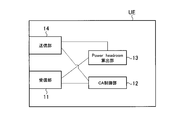
- the mobile station UE includes a transmission unit 11, a CA control unit 12, a power headroom calculation unit 13, and a reception unit 14.
- the receiving unit 11 is configured to receive a signal transmitted by the radio base station eNB.
- the receiving unit 11 is configured to receive an RRC message such as “RRC Connection Reconfiguration” instructing addition of a new DL CC from the radio base station.
- RRC message such as “RRC Connection Reconfiguration” instructing addition of a new DL CC from the radio base station.
- the receiving unit 11 is configured to receive a MAC signal such as “Active DL CC # X” instructing a change to an active state of a predetermined DL CC from the radio base station.
- the CA control unit 12 is configured to perform control related to CA communication by the mobile station UE.
- the CA control unit 12 adds a new CC in the RRC layer according to an instruction (specifically, an RRC message) from the radio base station eNB.
- the existing CC can be deleted, or the PCC can be changed.
- the CA control unit 12 performs CA communication in the MAC layer according to an instruction from the radio base station eNB (specifically, “MAC Control Element”). It is configured to set the state (active state or inactive state) of each CC used in FIG.
- the power headroom calculation unit 14 is configured to calculate a power headroom based on a path loss estimated from a predetermined DL CC.
- the power headroom calculating unit 14 is configured to calculate the power headroom based on the path loss estimated from the DL CC newly added by the CA control unit 12.
- the power headroom calculating unit 14 is configured to calculate the power headroom based on the path loss estimated from the predetermined DL CC that has been changed to the active state.
- the transmission unit 14 is configured to transmit a signal to the radio base station eNB.
- the transmission unit 14 is configured to transmit “MAC Control Element (PHR)” including the above power headroom to the radio base station eNB.
- PLR MAC Control Element
- the radio base station eNB includes a transmission unit 21, a reception unit 22, a CA control unit 23, and a scheduling unit 24.
- the transmission unit 21 is configured to transmit a signal to the mobile station UE.
- the transmission unit 21 instructs the mobile station UE to change the RRC message such as “RRC Connection Reconfiguration” instructing addition of a new DL CC, or to change the active state of a predetermined DL CC to “Active DL CC #”. It is configured to transmit a MAC signal such as “X”.
- the receiving unit 22 is configured to receive a signal transmitted by the mobile station UE.
- the receiving unit 22 is configured to receive a “MAC Control Element (PHR)” including a power headroom from the mobile station UE.
- PHR MAC Control Element
- the receiving unit 22 is configured to receive PHRs corresponding to the number of DL CCs used in CA communication by the mobile station UE.
- the receiving unit 22 may be configured to receive only PHRs corresponding to the number of DL CCs used by the mobile station UE for path loss estimation.
- the CA control unit 23 is configured to perform control related to CA communication by the mobile station UE.
- the CA control unit 23 uses the RRC message (for example, “RRC Reconfiguration” message or the like) in the RRC layer to add a new CC or an existing one to the mobile station UE performing CA communication. It is configured to be able to instruct deletion of the CC or change of the PCC.
- RRC message for example, “RRC Reconfiguration” message or the like
- CA control is performed.
- the unit 23 is configured to instruct addition of the second and subsequent DL CCs and UL CCs using the RRC message in the RRC layer.
- the CA control unit 23 is configured to instruct setting of the state (active state or inactive state) of each CC used in CA communication using “MAC Control Element” in the MAC layer. Has been.
- the scheduling unit 24 is configured to perform a scheduling process for the mobile station UE based on the PHR received by the receiving unit 22.
- the scheduling unit 24 assigns RB (Resource Block) in PUSCH, assigns TBS (Transport Block Size) in PUSCH, determines whether TTI bundling is applied, and performs SRS (Sounding). It is configured to determine the transmission bandwidth of the reference signal.
- RB Resource Block
- TBS Transport Block Size
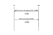
- step S1001 the radio base station eNB transmits “RRC Connection Reconfiguration” instructing the mobile station UE performing CA communication to add a new DL CC. .
- step S1002 the mobile station UE calculates a power headroom based on the path loss estimated from the newly added DL CC in accordance with the “RRC Connection Reconfiguration”, and the wireless base station eNB transmits the power to the power base station eNB.
- “MAC Control Element (PHR)” including the headroom is transmitted.
- step S2001 the radio base station eNB instructs the mobile station UE performing CA communication to change the existing DL CC to the active state “Active DL”.
- CC # X is transmitted.
- step S2002 the mobile station UE calculates the power headroom based on the path loss estimated from the DL CC that has been changed to the active state in accordance with the “Active DL CC # X”, and the radio base station eNB Then, “MAC Control Element (PHR)” including the Power headroom is transmitted.
- PHR MAC Control Element
- the mobile station UE instructs “RRC Connection Reconfiguration” instructing addition of a new DL CC or “Active DL CC # X” instructing to change an existing DL CC to an active state. ", The power baseroom calculated based on the path loss estimated from the DL CC is immediately transmitted to the radio base station eNB. Therefore, the radio base station eNB Appropriate scheduling in the UL CC related to the power headroom can be performed immediately.
- the first feature of the present embodiment is that the mobile station UE uses a plurality of DL CCs (downlink carriers) and a plurality of UL CCs (uplink carriers) having different carrier frequencies with the radio base station eNB.
- a mobile communication method for performing CA communication in which the radio base station eNB transmits “RRC Connection Reconfiguration (instruction signal)” instructing the mobile station UE to add a new DL CC, and the mobile station UE
- RRC Connection Reconfiguration instructing the mobile station UE to add a new DL CC
- the mobile station UE based on the path loss estimated from the new DL CC according to “RRC Connection Reconfiguration”, the difference information between the estimated value of the required transmission power in the PUSCH (uplink shared channel) and the maximum transmission power of the mobile station UE Calculating (Power headroom); Dokyoku UE to the radio base station eNB, and summarized in that a step of transmitting a "MAC Control Element (control information)" including the Power head
- a second feature of the present embodiment is a mobile communication method in which the mobile station UE performs CA communication using a plurality of DL CCs and a plurality of UL CCs having different carrier frequencies with the radio base station eNB.
- the radio base station eNB transmits “Active DL CC # X (instruction signal)” instructing the mobile station UE to change the predetermined DL CC to the active state, and the mobile station UE performs “Active In accordance with “DL CC # X”, the process of calculating the power headroom based on the path loss estimated from the predetermined DL CC, and the mobile station UE provides the “MAC Control Element including the power headroom to the radio base station eNB. And a step of transmitting ".”
- the third feature of the present embodiment is that the mobile station is configured to be able to perform CA communication using a plurality of DL CCs and a plurality of UL CCs having different carrier frequencies with the radio base station eNB.
- a new DL CC according to the receiving unit 12 that is a UE and configured to receive “RRC Connection Reconfiguration” instructing addition of a new DL CC from the radio base station eNB, and “RRC Connection Reconfiguration”.
- the power headroom calculation unit 14 configured to calculate the power headroom on the basis of the path loss estimated from the base station and the wireless base station eNB includes “MAC Control Element including the power headroom”.
- gist to a transmission unit 11 configured to transmit.
- a fourth feature of the present embodiment is that the mobile station is configured to perform CA communication using a plurality of DL CCs and a plurality of UL CCs having different carrier frequencies with the radio base station eNB.
- a UE 12 that is configured to receive an “Active DL CC # X” instructing a change to an active state of a predetermined DL CC from the radio base station eNB, and an “Active DL CC # X” ”Based on the path loss estimated from the predetermined DL CC, the power headroom calculating unit 14 configured to calculate the power headroom and the“ MAC Control including the power headroom ”to the radio base station eNB.
- the transmission unit 11 configured to transmit the “Element” And it is required to Bei.
- the operations of the mobile station UE and the radio base station eNB described above may be implemented by hardware, may be implemented by a software module executed by a processor, or may be implemented by a combination of both. .
- Software modules include RAM (Random Access Memory), flash memory, ROM (Read Only Memory), EPROM (Erasable Programmable ROM), EEPROM (Electronically Erasable and Programmable, Removable ROM, and Hard Disk). Alternatively, it may be provided in a storage medium of an arbitrary format such as a CD-ROM.
- Such a storage medium is connected to the processor so that the processor can read and write information from and to the storage medium. Further, such a storage medium may be integrated in the processor. Such a storage medium and processor may be provided in the ASIC. Such an ASIC may be provided in the mobile station UE or the radio base station eNB. Further, the storage medium and the processor may be provided as a discrete component in the mobile station UE or the radio base station eNB.
- UE ... mobile station eNB ... radio base station 14, 21 ... transmitting unit 11, 22 ... receiving unit 12, 23 ... CA control unit 13 ... Power headroom calculating unit 24 ... scheduling unit
Abstract
Description
図1乃至図5を参照して、本発明の第1の実施形態に係る移動通信システムの構成について説明する。
eNB…無線基地局
14、21…送信部
11、22…受信部
12、23…CA制御部
13…Power headroom算出部
24…スケジューリング部
Claims (4)
- 移動局が、無線基地局との間で、搬送波周波数が異なる複数の下りリンクキャリア及び複数の上りリンクキャリアを用いた通信を行う移動通信方法であって、
前記無線基地局が、前記移動局に対して、新規下りリンクキャリアの追加を指示する指示信号を送信する工程と、
前記移動局が、前記指示信号に応じて、前記新規下りリンクキャリアから推定されるパスロスに基づいて、上りリンク共有チャネルにおける所要の送信電力の推定値と該移動局の最大送信電力との差分情報を算出する工程と、
前記移動局が、前記無線基地局に対して、前記差分情報を含む制御情報を送信する工程とを有することを特徴とする移動通信方法。 - 移動局が、無線基地局との間で、搬送波周波数が異なる複数の下りリンクキャリア及び複数の上りリンクキャリアを用いた通信を行う移動通信方法であって、
前記無線基地局が、前記移動局に対して、所定下りリンクキャリアのアクティブ状態への変更を指示する指示信号を送信する工程と、
前記移動局が、前記指示信号に応じて、前記所定下りリンクキャリアから推定されるパスロスに基づいて、上りリンク共有チャネルにおける所要の送信電力の推定値と該移動局の最大送信電力との差分情報を算出する工程と、
前記移動局が、前記無線基地局に対して、前記差分情報を含む制御情報を送信する工程とを有することを特徴とする移動通信方法。 - 無線基地局との間で、搬送波周波数が異なる複数の下りリンクキャリア及び複数の上りリンクキャリアを用いた通信を行うことができるように構成されている移動局であって、
前記無線基地局から、新規下りリンクキャリアの追加を指示する指示信号を受信するように構成されている受信部と、
前記指示信号に応じて、前記新規下りリンクキャリアから推定されるパスロスに基づいて、上りリンク共有チャネルにおける所要の送信電力の推定値と該移動局の最大送信電力との差分情報を算出するように構成されている算出部と、
前記無線基地局に対して、前記差分情報を含む制御情報を送信するように構成されている送信部とを具備することを特徴とする移動局。 - 無線基地局との間で、搬送波周波数が異なる複数の下りリンクキャリア及び複数の上りリンクキャリアを用いた通信を行うことができるように構成されている移動局であって、
前記無線基地局から、所定下りリンクキャリアのアクティブ状態への変更を指示する指示信号を受信するように構成されている受信部と、
前記指示信号に応じて、前記所定下りリンクキャリアから推定されるパスロスに基づいて、上りリンク共有チャネルにおける所要の送信電力の推定値と該移動局の最大送信電力との差分情報を算出するように構成されている算出部と、
前記無線基地局に対して、前記差分情報を含む制御情報を送信するように構成されている送信部とを具備することを特徴とする移動局。
Priority Applications (9)
| Application Number | Priority Date | Filing Date | Title |
|---|---|---|---|
| KR1020127028949A KR101223999B1 (ko) | 2010-04-30 | 2011-04-28 | 이동통신방법 및 이동국 |
| AU2011246059A AU2011246059B9 (en) | 2010-04-30 | 2011-04-28 | Mobile communication method and mobile station |
| US13/261,502 US9025539B2 (en) | 2010-04-30 | 2011-04-28 | Mobile communication method and mobile station |
| EP11775132.1A EP2566231B1 (en) | 2010-04-30 | 2011-04-28 | Mobile communication method and mobile station |
| RU2012150158/07A RU2546335C2 (ru) | 2010-04-30 | 2011-04-28 | Способ мобильной связи и мобильная станция |
| MX2012012658A MX2012012658A (es) | 2010-04-30 | 2011-04-28 | Metodo de comunicacion movil y estacion movil. |
| PL11775132T PL2566231T3 (pl) | 2010-04-30 | 2011-04-28 | Sposób łączności komórkowej i stacja komórkowa |
| CN2011800217821A CN102870457B (zh) | 2010-04-30 | 2011-04-28 | 移动通信方法以及移动台 |
| ZA2012/08163A ZA201208163B (en) | 2010-04-30 | 2012-10-30 | Mobile communication method and mobile station |
Applications Claiming Priority (2)
| Application Number | Priority Date | Filing Date | Title |
|---|---|---|---|
| JP2010106012A JP4812887B1 (ja) | 2010-04-30 | 2010-04-30 | 移動通信方法及び移動局 |
| JP2010-106012 | 2010-04-30 |
Publications (1)
| Publication Number | Publication Date |
|---|---|
| WO2011136351A1 true WO2011136351A1 (ja) | 2011-11-03 |
Family
ID=44861645
Family Applications (1)
| Application Number | Title | Priority Date | Filing Date |
|---|---|---|---|
| PCT/JP2011/060417 WO2011136351A1 (ja) | 2010-04-30 | 2011-04-28 | 移動通信方法及び移動局 |
Country Status (11)
| Country | Link |
|---|---|
| US (1) | US9025539B2 (ja) |
| EP (1) | EP2566231B1 (ja) |
| JP (1) | JP4812887B1 (ja) |
| KR (1) | KR101223999B1 (ja) |
| CN (1) | CN102870457B (ja) |
| AU (1) | AU2011246059B9 (ja) |
| MX (1) | MX2012012658A (ja) |
| PL (1) | PL2566231T3 (ja) |
| RU (1) | RU2546335C2 (ja) |
| WO (1) | WO2011136351A1 (ja) |
| ZA (1) | ZA201208163B (ja) |
Cited By (1)
| Publication number | Priority date | Publication date | Assignee | Title |
|---|---|---|---|---|
| CN103118437A (zh) * | 2011-11-16 | 2013-05-22 | 华为技术有限公司 | 上行链路变更的方法、装置及系统 |
Families Citing this family (11)
| Publication number | Priority date | Publication date | Assignee | Title |
|---|---|---|---|---|
| KR101497370B1 (ko) | 2010-06-21 | 2015-03-03 | 노키아 솔루션스 앤드 네트웍스 오와이 | 전력 헤드룸 리포트를 이용한 캐리어 애그리게이션 |
| CN102300321B (zh) * | 2010-06-23 | 2015-07-22 | 电信科学技术研究院 | 多载波聚合系统中的功率余量上报方法、系统和设备 |
| WO2013004006A1 (en) * | 2011-07-05 | 2013-01-10 | Nokia Siemens Networks Oy | Method and apparatus for resource aggregation in wireless communications |
| JP2011250479A (ja) * | 2011-09-02 | 2011-12-08 | Ntt Docomo Inc | 移動通信方法及び移動局 |
| WO2014070069A1 (en) * | 2012-11-02 | 2014-05-08 | Telefonaktiebolaget L M Ericsson (Publ) | Network node, user node and methods for channel estimation |
| CN105027479B (zh) | 2013-01-26 | 2018-05-11 | Lg电子株式会社 | 在无线通信系统中通过ue接收下行链路控制信息的方法及其设备 |
| EP3113552B1 (en) * | 2014-03-24 | 2018-05-23 | Huawei Technologies Co. Ltd. | Method for controlling uplink power, user equipment, and base stations |
| WO2015159874A1 (ja) * | 2014-04-18 | 2015-10-22 | 株式会社Nttドコモ | ユーザ装置、及び上り送信電力情報送信方法 |
| CN105376035B (zh) * | 2014-08-28 | 2018-10-02 | 成都鼎桥通信技术有限公司 | 非对称上行载波聚合中辅载波的控制方法及装置 |
| CN117858215A (zh) * | 2019-09-29 | 2024-04-09 | 苹果公司 | 上行链路空间关系指示和功率控制 |
| CN114071680A (zh) * | 2020-07-31 | 2022-02-18 | 华为技术有限公司 | 一种通信方法及装置 |
Family Cites Families (19)
| Publication number | Priority date | Publication date | Assignee | Title |
|---|---|---|---|---|
| US20040147276A1 (en) * | 2002-12-17 | 2004-07-29 | Ralph Gholmieh | Reduced signaling power headroom feedback |
| US7570968B2 (en) * | 2003-12-29 | 2009-08-04 | Samsung Electronics Co., Ltd | Method and apparatus for adaptive open-loop power control in mobile communication system using TDD |
| US8452316B2 (en) * | 2004-06-18 | 2013-05-28 | Qualcomm Incorporated | Power control for a wireless communication system utilizing orthogonal multiplexing |
| CN101573896B (zh) * | 2006-11-08 | 2013-10-16 | 株式会社Ntt都科摩 | 移动通信系统、基站和移动台以及通信控制方法 |
| US8437792B2 (en) * | 2007-02-14 | 2013-05-07 | Qualcomm Incorporated | Uplink power control for LTE |
| RU2009134088A (ru) * | 2007-02-28 | 2011-04-10 | НТТ ДоСоМо, Инк. (JP) | Базовая станция и способ управления связью |
| TWM350187U (en) * | 2007-03-07 | 2009-02-01 | Interdigital Tech Corp | Wireless transmit receive unit |
| GB0716028D0 (en) * | 2007-08-16 | 2007-09-26 | Fujitsu Ltd | Communication systems |
| KR101459147B1 (ko) * | 2008-02-04 | 2014-11-10 | 엘지전자 주식회사 | 무선통신 시스템에서 전송 파워 제어 명령 전송 방법 |
| CN101572904A (zh) * | 2008-04-28 | 2009-11-04 | 华为技术有限公司 | 一种控制ue对临小区干扰的方法、装置及系统 |
| KR101722810B1 (ko) * | 2008-12-03 | 2017-04-05 | 인터디지탈 패튼 홀딩스, 인크 | 캐리어 집적에 대한 업링크 파워 헤드룸 보고 |
| TWI413431B (zh) * | 2009-03-23 | 2013-10-21 | Innovative Sonic Corp | 進行功率餘量回報的方法及通訊裝置 |
| EP3240335B1 (en) | 2009-05-22 | 2018-08-08 | BlackBerry Limited | Reporting power headroom for aggregated carriers |
| US8249091B2 (en) * | 2009-10-21 | 2012-08-21 | Samsung Electronics Co., Ltd | Power headroom reporting method and device for wireless communication system |
| EP2360866A1 (en) * | 2010-02-12 | 2011-08-24 | Panasonic Corporation | Component carrier activation and deactivation using resource assignments |
| WO2011160275A1 (zh) * | 2010-06-21 | 2011-12-29 | 上海贝尔股份有限公司 | 在载波汇聚网络中进行功率余量报告的方法 |
| WO2012011757A2 (ko) * | 2010-07-21 | 2012-01-26 | 엘지전자 주식회사 | 다수의 컴포넌트 캐리어를 지원하는 무선통신 시스템에서 파워 헤드룸 리포트를 전송하는 단말 장치 및 그 방법 |
| US9955431B2 (en) * | 2010-08-17 | 2018-04-24 | Google Technology Holdings LLC | Method and apparatus for power headroom reporting during multi-carrier operation |
| CN102448160B9 (zh) * | 2010-09-30 | 2016-06-15 | 中兴通讯股份有限公司 | 载波聚合场景下上报功率上升空间报告的方法和装置 |
-
2010
- 2010-04-30 JP JP2010106012A patent/JP4812887B1/ja active Active
-
2011
- 2011-04-28 EP EP11775132.1A patent/EP2566231B1/en active Active
- 2011-04-28 PL PL11775132T patent/PL2566231T3/pl unknown
- 2011-04-28 KR KR1020127028949A patent/KR101223999B1/ko active IP Right Grant
- 2011-04-28 US US13/261,502 patent/US9025539B2/en active Active
- 2011-04-28 MX MX2012012658A patent/MX2012012658A/es active IP Right Grant
- 2011-04-28 AU AU2011246059A patent/AU2011246059B9/en active Active
- 2011-04-28 CN CN2011800217821A patent/CN102870457B/zh active Active
- 2011-04-28 RU RU2012150158/07A patent/RU2546335C2/ru active
- 2011-04-28 WO PCT/JP2011/060417 patent/WO2011136351A1/ja active Application Filing
-
2012
- 2012-10-30 ZA ZA2012/08163A patent/ZA201208163B/en unknown
Non-Patent Citations (2)
| Title |
|---|
| "3GPP TS 36.321 V9.2.0", 3GPP TS 36.321 V9.2.0, March 2010 (2010-03-01), pages 26 - 27, XP050402557, Retrieved from the Internet <URL:http://www.3gpp.org/ftp/Specs/archive/36-series/36.321/36321-920.zip> [retrieved on 20110726] * |
| HTC: "Power Headroom Reporting", 3GPP TSG-RAN WG1 #60BIS R1-102309, 12 April 2010 (2010-04-12), XP050419731, Retrieved from the Internet <URL:http://www.3gpp.org/ftp/tsg_ran/WG1RL1/TSGR160b/Docs/R1-102309.zip> [retrieved on 20110726] * |
Cited By (1)
| Publication number | Priority date | Publication date | Assignee | Title |
|---|---|---|---|---|
| CN103118437A (zh) * | 2011-11-16 | 2013-05-22 | 华为技术有限公司 | 上行链路变更的方法、装置及系统 |
Also Published As
| Publication number | Publication date |
|---|---|
| PL2566231T3 (pl) | 2016-06-30 |
| JP4812887B1 (ja) | 2011-11-09 |
| AU2011246059A1 (en) | 2012-11-29 |
| JP2011239002A (ja) | 2011-11-24 |
| US9025539B2 (en) | 2015-05-05 |
| ZA201208163B (en) | 2014-01-29 |
| AU2011246059B9 (en) | 2015-05-21 |
| EP2566231A4 (en) | 2013-11-20 |
| EP2566231A1 (en) | 2013-03-06 |
| CN102870457A (zh) | 2013-01-09 |
| KR101223999B1 (ko) | 2013-01-21 |
| CN102870457B (zh) | 2013-11-13 |
| KR20120135435A (ko) | 2012-12-13 |
| US20130094450A1 (en) | 2013-04-18 |
| MX2012012658A (es) | 2012-12-17 |
| AU2011246059B2 (en) | 2015-05-14 |
| RU2546335C2 (ru) | 2015-04-10 |
| RU2012150158A (ru) | 2014-06-10 |
| EP2566231B1 (en) | 2016-03-16 |
Similar Documents
| Publication | Publication Date | Title |
|---|---|---|
| JP4812887B1 (ja) | 移動通信方法及び移動局 | |
| US10764834B2 (en) | Uplink transmission power control method and apparatus | |
| EP2894917B1 (en) | Mobile communication method, and mobile station | |
| EP3251262A1 (en) | Secondary scheduling request | |
| JP2011061706A (ja) | 移動通信システム、無線基地局及び移動局 | |
| WO2013141269A1 (ja) | 無線基地局及び移動局 | |
| JP5396330B2 (ja) | 移動通信方法、移動局及び無線基地局 | |
| JP4809487B1 (ja) | 移動通信方法及び移動局 | |
| WO2014050393A1 (ja) | 無線基地局及び移動局 | |
| WO2020077560A1 (en) | L1 signaling for serving cells | |
| JP2011250479A (ja) | 移動通信方法及び移動局 | |
| US10880054B2 (en) | Mobile station | |
| WO2011043393A1 (ja) | 基地局装置及び移動通信方法 | |
| JP6227968B2 (ja) | 移動局及び無線基地局 | |
| JP2010259018A (ja) | 無線基地局 | |
| JP2011239000A (ja) | 移動通信方法及び移動局 | |
| JP5487169B2 (ja) | 移動通信方法及び移動局 | |
| JP2016226057A (ja) | 移動局 |
Legal Events
| Date | Code | Title | Description |
|---|---|---|---|
| WWE | Wipo information: entry into national phase |
Ref document number: 201180021782.1 Country of ref document: CN |
|
| 121 | Ep: the epo has been informed by wipo that ep was designated in this application |
Ref document number: 11775132 Country of ref document: EP Kind code of ref document: A1 |
|
| NENP | Non-entry into the national phase |
Ref country code: DE |
|
| WWE | Wipo information: entry into national phase |
Ref document number: MX/A/2012/012658 Country of ref document: MX |
|
| ENP | Entry into the national phase |
Ref document number: 20127028949 Country of ref document: KR Kind code of ref document: A |
|
| WWE | Wipo information: entry into national phase |
Ref document number: 3378/KOLNP/2012 Country of ref document: IN |
|
| WWE | Wipo information: entry into national phase |
Ref document number: 2011775132 Country of ref document: EP |
|
| ENP | Entry into the national phase |
Ref document number: 2011246059 Country of ref document: AU Date of ref document: 20110428 Kind code of ref document: A |
|
| ENP | Entry into the national phase |
Ref document number: 2012150158 Country of ref document: RU Kind code of ref document: A |
|
| WWE | Wipo information: entry into national phase |
Ref document number: 13261502 Country of ref document: US |