WO2011132569A1 - 内燃機関の燃料供給制御装置 - Google Patents
内燃機関の燃料供給制御装置 Download PDFInfo
- Publication number
- WO2011132569A1 WO2011132569A1 PCT/JP2011/059091 JP2011059091W WO2011132569A1 WO 2011132569 A1 WO2011132569 A1 WO 2011132569A1 JP 2011059091 W JP2011059091 W JP 2011059091W WO 2011132569 A1 WO2011132569 A1 WO 2011132569A1
- Authority
- WO
- WIPO (PCT)
- Prior art keywords
- fuel
- internal combustion
- combustion engine
- switching
- water temperature
- Prior art date
- Legal status (The legal status is an assumption and is not a legal conclusion. Google has not performed a legal analysis and makes no representation as to the accuracy of the status listed.)
- Ceased
Links
Images

Classifications
-
- F—MECHANICAL ENGINEERING; LIGHTING; HEATING; WEAPONS; BLASTING
- F02—COMBUSTION ENGINES; HOT-GAS OR COMBUSTION-PRODUCT ENGINE PLANTS
- F02D—CONTROLLING COMBUSTION ENGINES
- F02D19/00—Controlling engines characterised by their use of non-liquid fuels, pluralities of fuels, or non-fuel substances added to the combustible mixtures
- F02D19/06—Controlling engines characterised by their use of non-liquid fuels, pluralities of fuels, or non-fuel substances added to the combustible mixtures peculiar to engines working with pluralities of fuels, e.g. alternatively with light and heavy fuel oil, other than engines indifferent to the fuel consumed
- F02D19/0626—Measuring or estimating parameters related to the fuel supply system
- F02D19/0628—Determining the fuel pressure, temperature or flow, the fuel tank fill level or a valve position
- F02D19/0631—Determining the fuel pressure, temperature or flow, the fuel tank fill level or a valve position by estimation, i.e. without using direct measurements of a corresponding sensor
-
- F—MECHANICAL ENGINEERING; LIGHTING; HEATING; WEAPONS; BLASTING
- F02—COMBUSTION ENGINES; HOT-GAS OR COMBUSTION-PRODUCT ENGINE PLANTS
- F02D—CONTROLLING COMBUSTION ENGINES
- F02D19/00—Controlling engines characterised by their use of non-liquid fuels, pluralities of fuels, or non-fuel substances added to the combustible mixtures
- F02D19/06—Controlling engines characterised by their use of non-liquid fuels, pluralities of fuels, or non-fuel substances added to the combustible mixtures peculiar to engines working with pluralities of fuels, e.g. alternatively with light and heavy fuel oil, other than engines indifferent to the fuel consumed
- F02D19/0602—Control of components of the fuel supply system
- F02D19/0613—Switch-over from one fuel to another
- F02D19/0615—Switch-over from one fuel to another being initiated by automatic means, e.g. based on engine or vehicle operating conditions
-
- F—MECHANICAL ENGINEERING; LIGHTING; HEATING; WEAPONS; BLASTING
- F02—COMBUSTION ENGINES; HOT-GAS OR COMBUSTION-PRODUCT ENGINE PLANTS
- F02D—CONTROLLING COMBUSTION ENGINES
- F02D19/00—Controlling engines characterised by their use of non-liquid fuels, pluralities of fuels, or non-fuel substances added to the combustible mixtures
- F02D19/06—Controlling engines characterised by their use of non-liquid fuels, pluralities of fuels, or non-fuel substances added to the combustible mixtures peculiar to engines working with pluralities of fuels, e.g. alternatively with light and heavy fuel oil, other than engines indifferent to the fuel consumed
- F02D19/0639—Controlling engines characterised by their use of non-liquid fuels, pluralities of fuels, or non-fuel substances added to the combustible mixtures peculiar to engines working with pluralities of fuels, e.g. alternatively with light and heavy fuel oil, other than engines indifferent to the fuel consumed characterised by the type of fuels
- F02D19/0642—Controlling engines characterised by their use of non-liquid fuels, pluralities of fuels, or non-fuel substances added to the combustible mixtures peculiar to engines working with pluralities of fuels, e.g. alternatively with light and heavy fuel oil, other than engines indifferent to the fuel consumed characterised by the type of fuels at least one fuel being gaseous, the other fuels being gaseous or liquid at standard conditions
- F02D19/0647—Controlling engines characterised by their use of non-liquid fuels, pluralities of fuels, or non-fuel substances added to the combustible mixtures peculiar to engines working with pluralities of fuels, e.g. alternatively with light and heavy fuel oil, other than engines indifferent to the fuel consumed characterised by the type of fuels at least one fuel being gaseous, the other fuels being gaseous or liquid at standard conditions the gaseous fuel being liquefied petroleum gas [LPG], liquefied natural gas [LNG], compressed natural gas [CNG] or dimethyl ether [DME]
-
- F—MECHANICAL ENGINEERING; LIGHTING; HEATING; WEAPONS; BLASTING
- F02—COMBUSTION ENGINES; HOT-GAS OR COMBUSTION-PRODUCT ENGINE PLANTS
- F02D—CONTROLLING COMBUSTION ENGINES
- F02D41/00—Electrical control of supply of combustible mixture or its constituents
- F02D41/0025—Controlling engines characterised by use of non-liquid fuels, pluralities of fuels, or non-fuel substances added to the combustible mixtures
- F02D41/0027—Controlling engines characterised by use of non-liquid fuels, pluralities of fuels, or non-fuel substances added to the combustible mixtures the fuel being gaseous
-
- F—MECHANICAL ENGINEERING; LIGHTING; HEATING; WEAPONS; BLASTING
- F02—COMBUSTION ENGINES; HOT-GAS OR COMBUSTION-PRODUCT ENGINE PLANTS
- F02D—CONTROLLING COMBUSTION ENGINES
- F02D41/00—Electrical control of supply of combustible mixture or its constituents
- F02D41/02—Circuit arrangements for generating control signals
- F02D41/04—Introducing corrections for particular operating conditions
- F02D41/06—Introducing corrections for particular operating conditions for engine starting or warming up
- F02D41/062—Introducing corrections for particular operating conditions for engine starting or warming up for starting
- F02D41/064—Introducing corrections for particular operating conditions for engine starting or warming up for starting at cold start
-
- F—MECHANICAL ENGINEERING; LIGHTING; HEATING; WEAPONS; BLASTING
- F02—COMBUSTION ENGINES; HOT-GAS OR COMBUSTION-PRODUCT ENGINE PLANTS
- F02D—CONTROLLING COMBUSTION ENGINES
- F02D19/00—Controlling engines characterised by their use of non-liquid fuels, pluralities of fuels, or non-fuel substances added to the combustible mixtures
- F02D19/06—Controlling engines characterised by their use of non-liquid fuels, pluralities of fuels, or non-fuel substances added to the combustible mixtures peculiar to engines working with pluralities of fuels, e.g. alternatively with light and heavy fuel oil, other than engines indifferent to the fuel consumed
- F02D19/0663—Details on the fuel supply system, e.g. tanks, valves, pipes, pumps, rails, injectors or mixers
- F02D19/0686—Injectors
- F02D19/0692—Arrangement of multiple injectors per combustion chamber
-
- F—MECHANICAL ENGINEERING; LIGHTING; HEATING; WEAPONS; BLASTING
- F02—COMBUSTION ENGINES; HOT-GAS OR COMBUSTION-PRODUCT ENGINE PLANTS
- F02D—CONTROLLING COMBUSTION ENGINES
- F02D2200/00—Input parameters for engine control
- F02D2200/02—Input parameters for engine control the parameters being related to the engine
- F02D2200/021—Engine temperature
-
- Y—GENERAL TAGGING OF NEW TECHNOLOGICAL DEVELOPMENTS; GENERAL TAGGING OF CROSS-SECTIONAL TECHNOLOGIES SPANNING OVER SEVERAL SECTIONS OF THE IPC; TECHNICAL SUBJECTS COVERED BY FORMER USPC CROSS-REFERENCE ART COLLECTIONS [XRACs] AND DIGESTS
- Y02—TECHNOLOGIES OR APPLICATIONS FOR MITIGATION OR ADAPTATION AGAINST CLIMATE CHANGE
- Y02T—CLIMATE CHANGE MITIGATION TECHNOLOGIES RELATED TO TRANSPORTATION
- Y02T10/00—Road transport of goods or passengers
- Y02T10/10—Internal combustion engine [ICE] based vehicles
- Y02T10/30—Use of alternative fuels, e.g. biofuels
Definitions
- the present invention relates to a fuel supply control device for an internal combustion engine, and more particularly to a fuel supply control device for an internal combustion engine capable of supplying a plurality of types of fuel to the internal combustion engine.
- a fuel supply control device for an internal combustion engine provided with a control means for performing multi-fuel switching control for switching and supplying these fuels according to at least the temperature conditions of the internal combustion engine.
- the multi-fuel engine according to Patent Document 1 switches between a first fuel and a second fuel that has a higher ability to raise the catalyst temperature due to unburned components than the first fuel, and has predetermined catalyst activation conditions. And a predetermined warm-up execution condition are satisfied, the second fuel is selected.
- the fuel supply device for an internal combustion engine according to Patent Document 2 selectively switches between two fuel supply systems based on a fuel switching request, and fuel is injected in the middle of fuel injection to a cylinder having a fuel supply system before switching. When a switching request occurs, the fuel supply system before switching is switched from a predetermined cylinder that injects fuel after the cylinder that is injecting fuel. It is.
- Patent Document 2 for example, in the case of a dual fuel vehicle using gasoline and CNG fuel, the operation with gasoline is continued until the internal combustion engine is completely warmed up. There was an unsatisfactory problem for requests to switch to small CNG fuel quickly. Even if the internal combustion engine operation is unstable immediately before fuel switching (open control or when there is an abnormality in the fuel system), fuel switching is performed. There was a risk of deterioration. Furthermore, since the switching condition between gasoline and CNG fuel is only the completion determination of complete warming, when restarting at full warming, the gasoline is immediately switched to CNG fuel, resulting in a situation where almost no gasoline is used. In this case, since the frequency of refueling gasoline is remarkably reduced, the aging of the gasoline may cause gum jamming in the fuel injection valve, leading to a poor starting of the internal combustion engine.
- An object of the present invention is to provide a fuel supply control device for an internal combustion engine that optimizes fuel switching, sets a fuel switching time that satisfies a driver's request, and prevents deterioration of drivability. There is.
- the present invention is a fuel supply control device for an internal combustion engine having control means for performing multi-fuel switching control for switching two or more kinds of fuels containing gaseous fuel and having different properties to supply them to the internal combustion engine, wherein the control means comprises: A switching permission water temperature lower than a complete warming determination temperature at which the internal combustion engine cooling water temperature can be determined to be completely warmed up, and a predetermined elapsed time after starting the internal combustion engine are secured. A switching permission time after starting is set, a specific fuel is supplied to the internal combustion engine at the time of starting the internal combustion engine, and the water temperature monitored after the start of the internal combustion engine exceeds the switching permission water temperature and is measured. When the elapsed time exceeds the post-start switching permission time, the specific fuel is switched to the gaseous fuel.
- the fuel supply control device for an internal combustion engine optimizes the fuel switching because the fuel switching is performed while balancing the reduction of the environmental load and ensuring the stability of starting the internal combustion engine. Thus, it is possible to set the fuel switching time that satisfies the driver's request and to prevent the drivability from deteriorating.
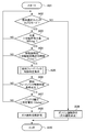
- FIG. 1 is a flowchart of fuel supply control of an internal combustion engine.
- FIG. 2 is a flowchart of fuel feedback control determination conditions.
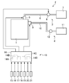
- FIG. 3 is a system configuration diagram of a fuel supply control device for an internal combustion engine.
- the present invention aims to optimize fuel switching, set a fuel switching time that satisfies a driver's request, and prevent deterioration of drivability. This is achieved by switching the fuel in a balance with ensuring safety.
- reference numeral 1 denotes an internal combustion engine mounted on a vehicle.
- the internal combustion engine 1 is a so-called bi-fuel engine in which a liquid specific fuel made of gasoline and a gaseous gaseous fuel made of CNG fuel are supplied as two or more kinds of fuels containing gaseous fuel and having different properties. is there.
- the internal combustion engine 1 is provided with a first fuel supply device 3 for specific fuel (gasoline) and a second fuel supply device 4 for gaseous fuel (CNG fuel) as two fuel supply devices 2. .
- the first fuel supply device 3 is connected to a fuel injection valve 5 attached to the internal combustion engine 1, a first fuel supply pipe 6 that guides fuel to the fuel injection valve 5, and the first fuel supply pipe 6.
- the first fuel tank 7 is provided.
- a fuel pump 8 is provided in the middle of the first fuel supply pipe 6.
- the first fuel tank 7 stores specific fuel.
- the second fuel supply device 4 includes a fuel supply valve 9 attached to the internal combustion engine 1, a second fuel supply pipe 10 that guides fuel to the fuel supply valve 9, and the second fuel supply pipe 10.
- the second fuel tank 11 is provided.
- a fuel regulator 12 that adjusts the pressure of the CNG fuel is provided in the middle of the second fuel supply pipe 10.
- the second fuel tank 11 stores gaseous fuel.
- the first fuel supply device 3 and the second fuel supply device 4 are controlled by a fuel supply control
- the fuel supply control device 13 includes control means (ECM) 14 that communicates with the fuel injection valve 5, the fuel pump 8, and the fuel supply valve 9.
- the control means 14 includes an ignition switch 15, a water temperature sensor 16 that detects the temperature of the cooling water of the internal combustion engine 1 as the temperature of the internal combustion engine, and a first fuel temperature sensor that detects the temperature of the specific fuel. 17, a second fuel temperature sensor 18 that detects the temperature of the gaseous fuel, an engine speed sensor 19 that detects the speed of the internal combustion engine 1, a battery voltage sensor 20 that detects the voltage of the battery, and a specific fuel And a fuel selection switch 21 for instructing whether or not to select the gaseous fuel in the auto (AUTO) mode.
- the first fuel temperature sensor 17 is attached to the inside of the first fuel tank 7 or the first fuel supply pipe 6.
- the second fuel temperature sensor 18 is attached to the inside of the second fuel tank 11 or the second fuel supply pipe 10.
- the control means 14 can supply the specific fuel and the gaseous fuel to the internal combustion engine 1, uses the specific fuel when starting the internal combustion engine 1, and switches and supplies these fuels at least according to the temperature condition of the internal combustion engine 1.
- a fuel switching control means 14A for performing multi-fuel switching control, a fuel supply amount control means 14B for controlling the fuel supply amount from the fuel injection valve 5 or the fuel supply valve to the internal combustion engine 1, and a temperature for determining the water temperature and the fuel temperature. 14C of determination means and the time measurement means (timer) 14D which measures time are provided.
- the control means 14 performs fuel feedback correction control to control the fuel supply amount when a predetermined fuel feedback correction control start condition (see FIG. 2) is satisfied. Fuel feedback correction control based on a general air-fuel ratio may be used.
- the control means 14 includes a switching permission water temperature (WTchg) lower than a complete warming determination temperature, which is a water temperature that can be determined as a fully warmed-up state of the internal combustion engine 1, and a predetermined elapsed time after the start of the internal combustion engine 1.
- WTchg switching permission water temperature
- Tchg post-start-up switching permission time
- the switching-permitted water temperature (WTchg) is set according to the water temperature at the start of the internal combustion engine 1, and is lower by a predetermined amount than the complete warming determination temperature, which is the water temperature that can be determined as the fully warmed-up state of the internal combustion engine 1. Set as temperature.
- the reason for judging the switching from the specific fuel to the gaseous fuel using this switching permission water temperature (WTchg) is to advance the fuel switching timing earlier than in the case of complete warm-up. Further, when the water temperature at the time of starting is low, the environmental temperature where the vehicle is placed is low and it is difficult to increase the water temperature. Therefore, the switching permission water temperature (WTchg) is set lower as the water temperature at the time of starting becomes lower.
- the post-startup switching permission time (Tchg) is set according to the water temperature at the start of the internal combustion engine 1, and the internal combustion engine 1 is continuously operated for a predetermined time, and a specific amount of specific fuel is consumed. It is set as the operation time that can be determined.
- the determination of switching from the specific fuel to the gaseous fuel using the post-startup switching permission time (Tchg) is to delay the fuel switching timing. Furthermore, by using the switching permission water temperature (WTchg) and the switching permission time after starting (Tchg) in combination, it is determined whether to switch from a specific fuel to a gaseous fuel (CNG fuel).
- the consumption of the specific fuel is ensured, that is, the usage rate of the specific fuel is improved in the situation where the temperature of the fuel is high, compared with the judgment of only the complete warm-up temperature be able to.
- the state in which the operation time using the specific fuel becomes longer than necessary thereby ensuring stable startability over a long period of time and ensuring reliability.
- Can do When the fuel temperature at the time of starting is low, the environment temperature where the vehicle is placed is low and the fuel temperature is difficult to rise. Therefore, the lower the fuel temperature at the time of starting, the lower the switching permission water temperature (WTchg).
- the control unit 14 sets and monitors the condition that the feedback correction amount of the fuel supplied to the internal combustion engine 1 is within a predetermined setting range and the condition that the fuel feedback correction control has passed a predetermined elapsed time.
- WTchg switching permission water temperature
- Tchg switching permission time
- control means 14 sets a predetermined determination voltage (Vbchg) to the battery voltage, monitors the battery voltage, and changes from the specific fuel to the gaseous fuel only when the battery voltage exceeds the determination voltage (Vbchg). Switch.
- step A01 when the internal combustion engine 1 is started when the program of the control means 14 is started (step A01), the specific fuel is supplied to the internal combustion engine 1. Then, the control means 14 determines whether or not the fuel selection switch 21 is in the auto (AUTO) mode (step A02). When this step A02 is YES, the program of the control means 14 judges whether or not the water temperature has exceeded the switching permission water temperature (WTchg) (step A03). If step A03 is NO, the process returns to step A02.
- WTchg switching permission water temperature
- step A04 determines whether or not a predetermined elapsed time after the start of the internal combustion engine 1 has exceeded a post-startup switching permission time (Tchg) (step A04). When this step A04 is NO, it returns to said step A02.
- step A05 the program of the control means 14 calculates
- the program of the control means 14 determines whether or not a fuel feedback control determination condition is satisfied (step A06). When this step A06 is NO, it returns to said step A02.
- step A06 the program of the control means 14 determines whether or not the battery voltage exceeds the determination voltage (Vbchg) (step A07). If step A07 is NO, the process returns to step A02. When this step A07 is YES, the program of the control means 14 permits switching from the specific fuel to the gaseous fuel (step A08). On the other hand, when the step A02 is NO, the program of the control means 14 instructs the operation of the specific fuel and prohibits the operation of the gaseous fuel (step A09). After the process of step A08 or after the process of step A09, the program is ended (step A10).
- step A05 in FIG. 1 The fuel feedback control determination condition in step A05 in FIG. 1 is obtained based on FIG. As shown in FIG. 2, when the program of the control means 14 is started (step B01), first, the ignition switch 15 is turned off, the fuel feedback correction control is not performed for a predetermined time or more, or the engine speed is zero. It is determined whether it is (0) (step B02). If step B02 is YES, the fuel feedback control determination condition is not satisfied (step B03). On the other hand, if step B02 is NO, the program of the control means 14 determines whether or not fuel feedback correction control has been started (step B04). When this step B04 is NO, it transfers to said step B03.
- Step B05 the program of the control means 14 indicates that the fuel feedback correction value (fuel feedback correction value) exceeds the lower predetermined value (CfbL) and is lower than the higher predetermined value (CfbH).
- Step B05 the program of the control means 14 determines whether or not the time after the start of the fuel feedback correction control (the time after the start of fuel feedback) exceeds a predetermined time (Tfbchg) (step S05).
- step B06 determines whether or not the time after the start of the fuel feedback correction control (the time after the start of fuel feedback) exceeds a predetermined time (Tfbchg) (step S05).
- Tfbchg predetermined time
- the program of the control means 14 includes a switching permission water temperature (WTchg) that is a water temperature lower than the complete warming determination temperature at which it can be determined that the internal combustion engine 1 is completely warmed up, and a predetermined progress after the internal combustion engine 1 is started.
- WTchg switching permission water temperature
- Tchg post-start-up switching permission time
- the program of the control means 14 is the case where the water temperature monitored after starting the internal combustion engine 1 exceeds the switching permission water temperature (WTchg) and the measured elapsed time exceeds the switching permission time after starting (Tchg).
- the specific fuel is switched to the gaseous fuel.
- the program of the control means 14 sets a condition that the feedback correction amount of the fuel supplied to the internal combustion engine 1 falls within a predetermined setting range, and a condition that the fuel feedback correction control has passed a predetermined elapsed time. To do.
- the program of the control means 14 is the case where the monitored water temperature exceeds the switching permission water temperature (WTchg) and the measured elapsed time exceeds the switching permission time (Tchg) after starting, and these fuels
- the specific fuel is switched to the gaseous fuel.
- the fuel is switched after the fluctuation of the fuel feedback correction control is suppressed. That is, the fuel is switched from a state in which stable operability of the internal combustion engine 1 can be ensured. For this reason, it is possible to prevent the drivability from being deteriorated after the internal combustion engine 1 is started and before and after the fuel is switched.
- the program of the control means 14 sets a predetermined determination voltage (Vbchg) to the battery voltage, monitors the battery voltage, and only when the battery voltage exceeds the determination voltage (Vbchg) Switch to fuel.
- Vbchg determination voltage
- the fuel is switched in a state where a stable fuel supply operation of each component (fuel supply valve, etc.) of the system is secured, thereby preventing deterioration of drivability. it can.
- a voltage that can ensure a stable fuel supply operation of each component (fuel supply valve or the like) of the system may be used as the determination voltage (Vbchg).
- the switching permission water temperature (WTchg) is set according to the water temperature when the internal combustion engine 1 is started, the timing for giving permission to switch the fuel before warm-up can be set optimally.
- the switching permission water temperature (WTchg) can be set according to the fuel temperature at the start of the fuel supplied to the internal combustion engine 1. Thereby, the timing which gives the switching permission before warm-up can be set optimally.
- the fuel supply control device according to the present invention can be applied to other internal combustion engines using LPG fuel or the like.
Landscapes
- Engineering & Computer Science (AREA)
- Chemical & Material Sciences (AREA)
- Combustion & Propulsion (AREA)
- Mechanical Engineering (AREA)
- General Engineering & Computer Science (AREA)
- Oil, Petroleum & Natural Gas (AREA)
- Electrical Control Of Air Or Fuel Supplied To Internal-Combustion Engine (AREA)
- Combined Controls Of Internal Combustion Engines (AREA)
- Output Control And Ontrol Of Special Type Engine (AREA)
Abstract
Description
特許文献2に係る内燃機関の燃料供給装置は、燃料切替要求に基づいて2系統の燃料供給系を選択的に切り換えるものであり、切換前の燃料供給系がある気筒に対する燃料噴射の途中に燃料切換要求が発生した場合に、切換前の燃料供給系が燃料噴射中の気筒より後に燃料噴射する所定気筒から、燃料供給系を切り換えるもので、暖機完了判定を実施して切換許可を出すものである。
また、燃料の切り換え直前で内燃機関の運転が不安定な状況(オープン制御若しくは燃料系に異常がある場合)にあっても、燃料の切り換えが実施されるため、燃料の切り換え後に、ドライバビリティの悪化が生じるおそれがあった。
更に、ガソリンとCNG燃料との切換条件が完暖完了判定のみのため、完暖での再始動時には、ガソリンからCNG燃料に即時に切り換るため、ガソリンを殆ど使用しない状況が発生してしまい、この場合、ガソリンの給油頻度が著しく低下するため、ガソリンの経年劣化により、燃料噴射弁にガム質づまりを引き起こしてしまい、内燃機関の始動不良を招くおそれがあった。
図3において、1は車両に搭載される内燃機関である。この内燃機関1は、ガス状燃料を含み性状の異なる2種以上の燃料として、例えば、ガソリンからなる液体の特定燃料とCNG燃料からなる気体のガス状燃料が供給される、いわゆるバイフューエルエンジンである。
第1の燃料供給装置3は、内燃機関1に取り付けられた燃料噴射弁5と、この燃料噴射弁5に燃料を導く第1の燃料供給管6と、この第1の燃料供給管6が接続した第1の燃料タンク7とを備える。第1の燃料供給管6の途中には、燃料ポンプ8が設けられている。
第1の燃料タンク7は、特定燃料を貯留するものである。
第2の燃料供給装置4は、内燃機関1に取り付けられた燃料供給弁9と、この燃料供給弁9に燃料を導く第2の燃料供給管10と、この第2の燃料供給管10が接続した第2の燃料タンク11とを備える。第2の燃料供給管10の途中には、CNG燃料の圧力を調整する燃料レギュレータ12が設けられている。第2の燃料タンク11は、ガス状燃料を貯留するものである。
この第1の燃料供給装置3と第2の燃料供給装置4とは、燃料供給制御装置13によって制御される。
また、この制御手段14には、イグニションスイッチ15と、内燃機関1の冷却水温度である水温を内燃機関の温度として検出する水温センサ16と、特定燃料の温度を検出する第1の燃料温度センサ17と、ガス状燃料の温度を検出する第2の燃料温度センサ18と、内燃機関1の回転数を検出するエンジン回転数センサ19と、バッテリの電圧を検出するバッテリ電圧センサ20と、特定燃料とガス状燃料との選択をオート(AUTO)モードで行うか否かを指令する燃料選択スイッチ21とが接続している。
第1の燃料温度センサ17は、第1の燃料タンク7の内部又は第1の燃料供給管6に取り付けられる。第2の燃料温度センサ18は、第2の燃料タンク11の内部又は第2の燃料供給管10に取り付けられる。
制御手段14は、燃料の供給制御を所定の燃料のフィードバック補正制御開始条件(図2参照)が成立した場合に、燃料のフィードバック補正制御を実施して燃料供給量を制御するものである。一般的な空燃比に基づく燃料のフィードバック補正制御で良い。
前記切換許可水温(WTchg)は、内燃機関1の始動時の水温に応じて設定されるものであり、内燃機関1の完全暖機状態と判定できる水温である完暖判定温度よりも所定量低い温度として設定される。この切換許可水温(WTchg)を用いて特定燃料からガス状燃料への切り換えを判断することは、燃料の切換時期を完全暖機時の場合よりも早めるためである。また、始動時の水温が低い場合は車両の置かれた環境温度が低く水温が上がり難い場合であるので、始動時の水温が低くなるほど切換許可水温(WTchg)を低く設定する。
また、前記始動後切換許可時間(Tchg)は、内燃機関1の始動時の水温に応じて設定されるものであり、内燃機関1を所定時間継続して運転し、特定燃料を所定量消費したと判定できる運転時間として設定される。この始動後切換許可時間(Tchg)を用いて特定燃料からガス状燃料への切り換えを判断することは、燃料の切換時期を遅らせるためである。
更に、前記切換許可水温(WTchg)と前記始動後切換許可時間(Tchg)とを併せて用い、特定燃料からガス状燃料(CNG燃料)への切り換えを判断することにより、短時間の内燃機関1の停止、車両の停止が繰り返される運転状況では、完全暖機温度のみの判断と比べて、特定燃料の消費量を確保、つまり、燃料の温度の高い状況での特定燃料の使用率を向上させることができる。一方、低温時等には、特定燃料を使用して運転する時間が、必要以上に長くなる状態を減らすことができ、これにより、長期にわたって安定した始動性を確保でき、信頼性を確保することができる。始動時の燃料温度が低い場合は車両の置かれた環境温度が低く燃料温度が上がり難い場合であるので、始動時の燃料温度が低くなるほど切換許可水温(WTchg)を低く設定する。
図1に示すように、制御手段14のプログラムがスタートした内燃機関1の始動時には(ステップA01)、内燃機関1へは特定燃料が供給される。そして、制御手段14は、燃料選択スイッチ21がオート(AUTO)モードが否かを判断する(ステップA02)。
このステップA02がYESの場合には、制御手段14のプログラムは、水温が切換許可水温(WTchg)を超えたか否かを判断する(ステップA03)。このステップA03がNOの場合には、前記ステップA02に戻す。
このステップA03がYESの場合には、制御手段14のプログラムは、内燃機関1の始動後の所定の経過時間が始動後切換許可時間(Tchg)を超えたか否かを判断する(ステップA04)。このステップA04がNOの場合には、前記ステップA02に戻す。
このステップA04がYESの場合には、制御手段14のプログラムは、燃料のフィードバック制御判定条件を求める(ステップA05)。この燃料のフィードバック制御判定条件については、後述の図2のフローチャートで説明する。
そして、制御手段14のプログラムは、燃料のフィードバック制御判定条件が成立したか否かを判断する(ステップA06)。このステップA06がNOの場合には、前記ステップA02に戻す。
このステップA06がYESの場合には、制御手段14のプログラムは、バッテリ電圧が判定電圧(Vbchg)を超えたか否かを判断する(ステップA07)。このステップA07がNOの場合には、前記ステップA02に戻す。
このステップA07がYESの場合には、制御手段14のプログラムは、特定燃料からガス状燃料への切り換えを許可する(ステップA08)。
一方、前記ステップA02がNOの場合には、制御手段14のプログラムは、特定燃料の運転を指示して、ガス状燃料の運転を禁止する(ステップA09)。
前記ステップA08の処理後、又は、前記ステップA09の処理後は、プログラムをエンドとする(ステップA10)。
図2に示すように、制御手段14のプログラムがスタートすると(ステップB01)、先ず、イグニションスイッチ15がオフか、又は、所定時間以上燃料のフィードバック補正制御中でないか、又は、エンジン回転数が零(0)かを、判断する(ステップB02)。
このステップB02がYESの場合には、燃料のフィードバック制御判定条件が不成立とする(ステップB03)。
一方、このステップB02がNOの場合には、制御手段14のプログラムは、燃料のフィードバック補正制御を開始したか否かを判断する(ステップB04)。このステップB04がNOの場合には、前記ステップB03に移行する。
このステップB04がYESの場合には、制御手段14のプログラムは、燃料のフィードバック補正値(燃料フィードバック補正値)が、低い側の所定値(CfbL)を超え且つ高い側の所定値(CfbH)未満か否かを判断する(ステップB05)。このステップB05がNOの場合には、前記ステップB03に移行する。
このステップB05がYESの場合には、制御手段14のプログラムは、燃料のフィードバック補正制御の開始後の時間(燃料フィードバック開始後時間)が所定時間(Tfbchg)を超えたか否かを判断する(ステップB06)。このステップB06がNOの場合には、前記ステップB03に移行する。
このステップB06がYESの場合には、燃料フィードバック制御判定条件が成立したとする(ステップB07)。
前記ステップB03の処理後、又は、前記ステップB07の処理後は、プログラムを戻す(ステップB08)。
また、制御手段14のプログラムは、内燃機関1に供給される燃料のフィードバック補正量が所定の設定範囲に収まる条件と、燃料のフィードバック補正制御が所定の経過時間を経過している条件とを設定する。そして、制御手段14のプログラムは、監視された水温が前記切換許可水温(WTchg)を超え且つ計測された経過時間が始動後切換許可時間(Tchg)を超えた場合であって、且つこれらの燃料フィードバック制御判定条件が成立する場合に、特定燃料からガス状燃料へ切り換える。このように、燃料のフィードバック補正制御の変動が抑制された後に燃料を切り換えることになる。つまり、内燃機関1の安定的な運転性を確保できた状態から燃料を切換ることになる。このため、内燃機関1の始動後や、燃料の切換前後でのドライバビリティの悪化を防ぐことができる。
更に、制御手段14のプログラムは、バッテリ電圧に所定の判定電圧(Vbchg)を設定し、バッテリ電圧を監視してバッテリ電圧が前記判定電圧(Vbchg)を超えている場合にのみ、特定燃料からガス状燃料へ切り換える。このように、複数の燃料供給経路を持つ燃料供給システムにおいて、システムの各部品(燃料供給弁等)の安定した燃料供給動作が確保された状態下で燃料を切り換えるので、ドライバビリティの悪化を防止できる。システムの各部品(燃料供給弁等)の安定した燃料供給動作が確保できる電圧を判定電圧(Vbchg)とすれば良い。
更にまた、前記切換許可水温(WTchg)を内燃機関1の始動時の水温に応じて設定することから、暖機前の燃料の切換許可を与えるタイミングを最適に設定できる。
Claims (5)
- ガス状燃料を含み性状の異なる2種以上の燃料を切り替えて内燃機関に供給する多種燃料切換制御を行う制御手段を有する内燃機関の燃料供給制御装置であって、
前記制御手段は、前記内燃機関の冷却水の水温であって前記内燃機関が完全暖機状態であると判定できる完暖判定温度よりも低い切換許可水温と、前記内燃機関の始動後の所定の経過時間を確保する始動後切換許可時間とを設定し、前記内燃機関の始動時においては特定燃料を前記内燃機関に供給し、前記内燃機関の始動後で監視された前記水温が前記切換許可水温を超え且つ計測された経過時間が前記始動後切換許可時間を超えた場合には前記特定燃料からガス状燃料へ切り換えることを特徴とする内燃機関の燃料供給制御装置。 - 前記制御手段は、前記内燃機関に供給される燃料のフィードバック補正量が所定の設定範囲に収まる条件と、燃料のフィードバック補正制御が所定の経過時間を経過している条件とを設定し、監視された前記水温が前記切換許可水温を超え且つ計測された経過時間が始動後切換許可時間を超えた場合であって、且つ設定した二つの前記条件が成立する場合に、特定燃料からガス状燃料へ切り換えることを特徴とする請求項1に記載の内燃機関の燃料供給制御装置。
- 前記制御手段は、バッテリ電圧に所定の判定電圧を設定し、前記バッテリ電圧を監視して前記バッテリ電圧が前記判定電圧を超えている場合にのみ、前記特定燃料から前記ガス状燃料へ切り換えることを特徴とする請求項1に記載の内燃機関の燃料供給制御装置。
- 前記制御手段は、前記切換許可水温を前記内燃機関の始動時の前記水温に応じて設定することを特徴とする請求項1に記載の内燃機関の燃料供給制御装置。
- 前記制御手段は、前記切換許可水温を前記内燃機関に供給する燃料の始動時の燃料温度に応じて設定することを特徴とする請求項1に記載の内燃機関の燃料供給制御装置。
Priority Applications (3)
| Application Number | Priority Date | Filing Date | Title |
|---|---|---|---|
| CN201180020033.7A CN102859150B (zh) | 2010-04-20 | 2011-04-12 | 用于内燃机的燃料供给控制装置 |
| DE112011101398.1T DE112011101398B4 (de) | 2010-04-20 | 2011-04-12 | Brennstoffzufuhrsteuervorrichtung für Brennkraftmaschine |
| JP2012511620A JP5729380B2 (ja) | 2010-04-20 | 2011-04-12 | 内燃機関の燃料供給制御装置 |
Applications Claiming Priority (2)
| Application Number | Priority Date | Filing Date | Title |
|---|---|---|---|
| JP2010096861 | 2010-04-20 | ||
| JP2010-096861 | 2010-04-20 |
Publications (1)
| Publication Number | Publication Date |
|---|---|
| WO2011132569A1 true WO2011132569A1 (ja) | 2011-10-27 |
Family
ID=44834093
Family Applications (1)
| Application Number | Title | Priority Date | Filing Date |
|---|---|---|---|
| PCT/JP2011/059091 Ceased WO2011132569A1 (ja) | 2010-04-20 | 2011-04-12 | 内燃機関の燃料供給制御装置 |
Country Status (4)
| Country | Link |
|---|---|
| JP (1) | JP5729380B2 (ja) |
| CN (1) | CN102859150B (ja) |
| DE (1) | DE112011101398B4 (ja) |
| WO (1) | WO2011132569A1 (ja) |
Cited By (2)
| Publication number | Priority date | Publication date | Assignee | Title |
|---|---|---|---|---|
| CN113153545A (zh) * | 2021-04-12 | 2021-07-23 | 上汽依维柯红岩商用车有限公司 | 一种柴油商用车双油箱切换控制系统及其控制方法 |
| JP7251598B1 (ja) | 2021-11-10 | 2023-04-04 | いすゞ自動車株式会社 | 燃料供給制御装置および車両 |
Families Citing this family (5)
| Publication number | Priority date | Publication date | Assignee | Title |
|---|---|---|---|---|
| AT517215B1 (de) * | 2015-06-23 | 2016-12-15 | Avl List Gmbh | Verfahren zum Regeln einer Konditioniereinheit und Verbrauchsmesseinrichtung mit einer solchen Konditioniereinheit |
| DE102016211792A1 (de) * | 2016-06-30 | 2018-01-04 | Continental Automotive Gmbh | Gasbrennkraftmaschine mit Hilfsstartsystem und Verfahren zum Betreiben einer Gasbrennkraftmaschine |
| DE102018108097A1 (de) * | 2018-04-05 | 2019-10-10 | Volkswagen Aktiengesellschaft | Verfahren zum Betreiben einer Verbrennungskraftmaschine eines Antriebssystems für ein Kraftfahrzeug, Antriebssystem und Kraftfahrzeug |
| CN116255266A (zh) * | 2023-04-25 | 2023-06-13 | 浙江吉利控股集团有限公司 | 甲醇发动机控制方法、电子设备及存储介质 |
| CN116816518B (zh) * | 2023-07-10 | 2025-10-03 | 浙江吉利控股集团有限公司 | 燃料切换控制方法、车辆及计算机存储介质 |
Citations (4)
| Publication number | Priority date | Publication date | Assignee | Title |
|---|---|---|---|---|
| JP2003074415A (ja) * | 2001-09-05 | 2003-03-12 | Aisan Ind Co Ltd | 内燃機関における燃料供給方法とその装置 |
| JP2005207341A (ja) * | 2004-01-23 | 2005-08-04 | Aisan Ind Co Ltd | エンジンの燃料供給方法と燃料供給装置 |
| JP2007051550A (ja) * | 2005-08-15 | 2007-03-01 | Kubota Corp | 液体燃料エンジンおよびデュアル燃料エンジン |
| JP2009264354A (ja) * | 2008-04-21 | 2009-11-12 | Teito Sangyo Kk | バイフューエルエンジン始動後の燃料自動切換装置 |
Family Cites Families (6)
| Publication number | Priority date | Publication date | Assignee | Title |
|---|---|---|---|---|
| JP2005233135A (ja) * | 2004-02-20 | 2005-09-02 | Toyota Motor Corp | 多種燃料機関 |
| JP2006336499A (ja) | 2005-05-31 | 2006-12-14 | Aisan Ind Co Ltd | 内燃機関の燃料供給装置 |
| DE102006025259A1 (de) * | 2006-05-31 | 2007-12-06 | Volkswagen Ag | Bivalente Brennkraftmaschine und Verfahren zum Betrieb einer bivalenten Brennkraftmaschine |
| JP4535051B2 (ja) * | 2006-09-28 | 2010-09-01 | トヨタ自動車株式会社 | 多種燃料内燃機関 |
| JP4765941B2 (ja) * | 2007-01-09 | 2011-09-07 | トヨタ自動車株式会社 | 内燃機関の制御装置及び方法 |
| DE102007044522B4 (de) * | 2007-09-18 | 2019-01-17 | Man Diesel & Turbo Se | Vorrichtung zur Regelung eines mit flüssigem und/oder gasförmigen Kraftstoff betreibbaren Verbrennungsmotors |
-
2011
- 2011-04-12 DE DE112011101398.1T patent/DE112011101398B4/de active Active
- 2011-04-12 WO PCT/JP2011/059091 patent/WO2011132569A1/ja not_active Ceased
- 2011-04-12 CN CN201180020033.7A patent/CN102859150B/zh not_active Expired - Fee Related
- 2011-04-12 JP JP2012511620A patent/JP5729380B2/ja active Active
Patent Citations (4)
| Publication number | Priority date | Publication date | Assignee | Title |
|---|---|---|---|---|
| JP2003074415A (ja) * | 2001-09-05 | 2003-03-12 | Aisan Ind Co Ltd | 内燃機関における燃料供給方法とその装置 |
| JP2005207341A (ja) * | 2004-01-23 | 2005-08-04 | Aisan Ind Co Ltd | エンジンの燃料供給方法と燃料供給装置 |
| JP2007051550A (ja) * | 2005-08-15 | 2007-03-01 | Kubota Corp | 液体燃料エンジンおよびデュアル燃料エンジン |
| JP2009264354A (ja) * | 2008-04-21 | 2009-11-12 | Teito Sangyo Kk | バイフューエルエンジン始動後の燃料自動切換装置 |
Cited By (6)
| Publication number | Priority date | Publication date | Assignee | Title |
|---|---|---|---|---|
| CN113153545A (zh) * | 2021-04-12 | 2021-07-23 | 上汽依维柯红岩商用车有限公司 | 一种柴油商用车双油箱切换控制系统及其控制方法 |
| JP7251598B1 (ja) | 2021-11-10 | 2023-04-04 | いすゞ自動車株式会社 | 燃料供給制御装置および車両 |
| WO2023084908A1 (ja) * | 2021-11-10 | 2023-05-19 | いすゞ自動車株式会社 | 燃料供給制御装置および車両 |
| JP2023070899A (ja) * | 2021-11-10 | 2023-05-22 | いすゞ自動車株式会社 | 燃料供給制御装置および車両 |
| US20250003372A1 (en) * | 2021-11-10 | 2025-01-02 | Isuzu Motors Limited | Fuel supply control device and vehicle |
| US12359631B2 (en) | 2021-11-10 | 2025-07-15 | Isuzu Motors Limited | Fuel supply control device and vehicle |
Also Published As
| Publication number | Publication date |
|---|---|
| JPWO2011132569A1 (ja) | 2013-07-18 |
| DE112011101398T5 (de) | 2013-03-21 |
| JP5729380B2 (ja) | 2015-06-03 |
| DE112011101398B4 (de) | 2016-12-15 |
| CN102859150A (zh) | 2013-01-02 |
| CN102859150B (zh) | 2015-09-23 |
Similar Documents
| Publication | Publication Date | Title |
|---|---|---|
| JP5729380B2 (ja) | 内燃機関の燃料供給制御装置 | |
| US8485165B2 (en) | Fuel control system and associated method | |
| EP2469058B1 (en) | Apparatus and method for controlling fuel injection in a bi-fuel vehicle running on two fuels, i.e. gasoline and lpg | |
| JP4321280B2 (ja) | バイフューエルエンジンの始動制御方法並びに停止制御方法 | |
| JP4747687B2 (ja) | バイフューエルエンジンの制御装置 | |
| EP2551496B1 (en) | Control device for internal combustion engine | |
| CN103261639B (zh) | 用于控制内燃机以考虑燃料特性的方法 | |
| JP2006336499A (ja) | 内燃機関の燃料供給装置 | |
| KR100624226B1 (ko) | 엘피지 차량의 시동 시점 지시장치 및 방법 | |
| KR101281390B1 (ko) | 바이 퓨얼 엔진시스템에서의 연료전환방법 | |
| KR100706552B1 (ko) | 엘피아이 차량의 시동장치 및 그 제어방법 | |
| KR20060028550A (ko) | 엘피지 액상 인젝션 시스템의 시동성 향상을 위한 펌프제어방법 | |
| KR100907371B1 (ko) | 엘피아이 차량의 가스 인젝션 신호 제어 방법 | |
| KR20120117507A (ko) | 바이-퓨얼 시스템 및 그 시스템의 연료모드 전환 제어 방법 | |
| JP2020002849A (ja) | 制御装置 | |
| JP2007056679A (ja) | エンジンのlpg燃料供給装置 | |
| KR100758489B1 (ko) | 엘피아이 차량의 재시동성 개선 시스템 및 그 방법 | |
| KR200294203Y1 (ko) | 학습제어 엔진 전자제어장치에 대응하는 엘피지와 가솔린겸용 차량의 인젝터 차단 제어장치 | |
| JP2016133111A (ja) | 加熱装置 | |
| KR20100116539A (ko) | 가스 연료 공급 장치 | |
| TH2401002965A (th) | อุปกรณ์ควบคุมการจ่ายเชื้อเพลิงและยานพาหนะ | |
| JP2013174154A (ja) | 車両の燃料噴射制御装置 | |
| JP2017223208A (ja) | バイフューエルエンジンの燃料噴射切換装置 | |
| KR20170126216A (ko) | 바이퓨얼 차량의 엔진 제어 장치 및 방법 | |
| JP2014125882A (ja) | 制御装置 |
Legal Events
| Date | Code | Title | Description |
|---|---|---|---|
| WWE | Wipo information: entry into national phase |
Ref document number: 201180020033.7 Country of ref document: CN |
|
| 121 | Ep: the epo has been informed by wipo that ep was designated in this application |
Ref document number: 11771904 Country of ref document: EP Kind code of ref document: A1 |
|
| WWE | Wipo information: entry into national phase |
Ref document number: 2012511620 Country of ref document: JP |
|
| WWE | Wipo information: entry into national phase |
Ref document number: 8845/DELNP/2012 Country of ref document: IN |
|
| WWE | Wipo information: entry into national phase |
Ref document number: 1120111013981 Country of ref document: DE Ref document number: 112011101398 Country of ref document: DE |
|
| 122 | Ep: pct application non-entry in european phase |
Ref document number: 11771904 Country of ref document: EP Kind code of ref document: A1 |