WO2011132429A1 - Vehicle air conditioning device - Google Patents
Vehicle air conditioning device Download PDFInfo
- Publication number
- WO2011132429A1 WO2011132429A1 PCT/JP2011/002339 JP2011002339W WO2011132429A1 WO 2011132429 A1 WO2011132429 A1 WO 2011132429A1 JP 2011002339 W JP2011002339 W JP 2011002339W WO 2011132429 A1 WO2011132429 A1 WO 2011132429A1
- Authority
- WO
- WIPO (PCT)
- Prior art keywords
- heat exchanger
- indoor heat
- refrigerant
- flow path
- duct
- Prior art date
Links
Images


Classifications
-
- B—PERFORMING OPERATIONS; TRANSPORTING
- B60—VEHICLES IN GENERAL
- B60H—ARRANGEMENTS OF HEATING, COOLING, VENTILATING OR OTHER AIR-TREATING DEVICES SPECIALLY ADAPTED FOR PASSENGER OR GOODS SPACES OF VEHICLES
- B60H1/00—Heating, cooling or ventilating [HVAC] devices
- B60H1/00642—Control systems or circuits; Control members or indication devices for heating, cooling or ventilating devices
- B60H1/00814—Control systems or circuits characterised by their output, for controlling particular components of the heating, cooling or ventilating installation
- B60H1/00878—Control systems or circuits characterised by their output, for controlling particular components of the heating, cooling or ventilating installation the components being temperature regulating devices
- B60H1/00899—Controlling the flow of liquid in a heat pump system
- B60H1/00907—Controlling the flow of liquid in a heat pump system where the flow direction of the refrigerant changes and an evaporator becomes condenser
-
- B—PERFORMING OPERATIONS; TRANSPORTING
- B60—VEHICLES IN GENERAL
- B60H—ARRANGEMENTS OF HEATING, COOLING, VENTILATING OR OTHER AIR-TREATING DEVICES SPECIALLY ADAPTED FOR PASSENGER OR GOODS SPACES OF VEHICLES
- B60H1/00—Heating, cooling or ventilating [HVAC] devices
- B60H1/32—Cooling devices
- B60H1/3204—Cooling devices using compression
- B60H1/3205—Control means therefor
- B60H1/3213—Control means therefor for increasing the efficiency in a vehicle heat pump
-
- B—PERFORMING OPERATIONS; TRANSPORTING
- B60—VEHICLES IN GENERAL
- B60H—ARRANGEMENTS OF HEATING, COOLING, VENTILATING OR OTHER AIR-TREATING DEVICES SPECIALLY ADAPTED FOR PASSENGER OR GOODS SPACES OF VEHICLES
- B60H1/00—Heating, cooling or ventilating [HVAC] devices
- B60H1/00642—Control systems or circuits; Control members or indication devices for heating, cooling or ventilating devices
- B60H1/00814—Control systems or circuits characterised by their output, for controlling particular components of the heating, cooling or ventilating installation
- B60H1/00878—Control systems or circuits characterised by their output, for controlling particular components of the heating, cooling or ventilating installation the components being temperature regulating devices
- B60H1/00899—Controlling the flow of liquid in a heat pump system
-
- B—PERFORMING OPERATIONS; TRANSPORTING
- B60—VEHICLES IN GENERAL
- B60H—ARRANGEMENTS OF HEATING, COOLING, VENTILATING OR OTHER AIR-TREATING DEVICES SPECIALLY ADAPTED FOR PASSENGER OR GOODS SPACES OF VEHICLES
- B60H1/00—Heating, cooling or ventilating [HVAC] devices
- B60H1/00642—Control systems or circuits; Control members or indication devices for heating, cooling or ventilating devices
- B60H1/00814—Control systems or circuits characterised by their output, for controlling particular components of the heating, cooling or ventilating installation
- B60H1/00878—Control systems or circuits characterised by their output, for controlling particular components of the heating, cooling or ventilating installation the components being temperature regulating devices
- B60H2001/00935—Control systems or circuits characterised by their output, for controlling particular components of the heating, cooling or ventilating installation the components being temperature regulating devices comprising four way valves for controlling the fluid direction
-
- B—PERFORMING OPERATIONS; TRANSPORTING
- B60—VEHICLES IN GENERAL
- B60H—ARRANGEMENTS OF HEATING, COOLING, VENTILATING OR OTHER AIR-TREATING DEVICES SPECIALLY ADAPTED FOR PASSENGER OR GOODS SPACES OF VEHICLES
- B60H1/00—Heating, cooling or ventilating [HVAC] devices
- B60H1/32—Cooling devices
- B60H2001/3236—Cooling devices information from a variable is obtained
- B60H2001/3248—Cooling devices information from a variable is obtained related to pressure
- B60H2001/325—Cooling devices information from a variable is obtained related to pressure of the refrigerant at a compressing unit
-
- B—PERFORMING OPERATIONS; TRANSPORTING
- B60—VEHICLES IN GENERAL
- B60H—ARRANGEMENTS OF HEATING, COOLING, VENTILATING OR OTHER AIR-TREATING DEVICES SPECIALLY ADAPTED FOR PASSENGER OR GOODS SPACES OF VEHICLES
- B60H1/00—Heating, cooling or ventilating [HVAC] devices
- B60H1/32—Cooling devices
- B60H2001/3236—Cooling devices information from a variable is obtained
- B60H2001/3255—Cooling devices information from a variable is obtained related to temperature
-
- B—PERFORMING OPERATIONS; TRANSPORTING
- B60—VEHICLES IN GENERAL
- B60H—ARRANGEMENTS OF HEATING, COOLING, VENTILATING OR OTHER AIR-TREATING DEVICES SPECIALLY ADAPTED FOR PASSENGER OR GOODS SPACES OF VEHICLES
- B60H1/00—Heating, cooling or ventilating [HVAC] devices
- B60H1/32—Cooling devices
- B60H2001/3269—Cooling devices output of a control signal
- B60H2001/327—Cooling devices output of a control signal related to a compressing unit
-
- B—PERFORMING OPERATIONS; TRANSPORTING
- B60—VEHICLES IN GENERAL
- B60H—ARRANGEMENTS OF HEATING, COOLING, VENTILATING OR OTHER AIR-TREATING DEVICES SPECIALLY ADAPTED FOR PASSENGER OR GOODS SPACES OF VEHICLES
- B60H1/00—Heating, cooling or ventilating [HVAC] devices
- B60H1/32—Cooling devices
- B60H2001/3269—Cooling devices output of a control signal
- B60H2001/3285—Cooling devices output of a control signal related to an expansion unit
-
- F—MECHANICAL ENGINEERING; LIGHTING; HEATING; WEAPONS; BLASTING
- F25—REFRIGERATION OR COOLING; COMBINED HEATING AND REFRIGERATION SYSTEMS; HEAT PUMP SYSTEMS; MANUFACTURE OR STORAGE OF ICE; LIQUEFACTION SOLIDIFICATION OF GASES
- F25B—REFRIGERATION MACHINES, PLANTS OR SYSTEMS; COMBINED HEATING AND REFRIGERATION SYSTEMS; HEAT PUMP SYSTEMS
- F25B2313/00—Compression machines, plants or systems with reversible cycle not otherwise provided for
- F25B2313/023—Compression machines, plants or systems with reversible cycle not otherwise provided for using multiple indoor units
- F25B2313/0234—Compression machines, plants or systems with reversible cycle not otherwise provided for using multiple indoor units in series arrangements
- F25B2313/02343—Compression machines, plants or systems with reversible cycle not otherwise provided for using multiple indoor units in series arrangements during dehumidification
Definitions
- the present invention relates to a vehicle air conditioner that cools and heats a passenger compartment.
- a heat pump is used for cooling, while waste heat of the engine is used for heating.
- cooling is performed while circulating air in the passenger compartment, and heating is performed while introducing outside air with low humidity.
- the vehicle air conditioner is required to have a function of dehumidifying the air in the passenger compartment even during heating.
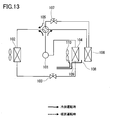
- Patent Document 1 discloses an air conditioner for an electric vehicle as shown in FIG.
- This air conditioner forms a compressor 101 driven by an electric motor, an outdoor heat exchanger 102, an expansion valve 103, an indoor heat absorption heat exchanger 104, and a loop that passes through these devices 101 to 104 in this order during cooling operation.
- a four-way valve 105 is provided. Further, the other two ports of the four-way valve 105 are connected to the indoor heat radiating heat exchanger 106 and the expansion valve 107 so as to form another loop.
- the indoor heat absorption heat exchanger 104 is supplied with air in the passenger compartment by a fan 110.
- the indoor heat-dissipating heat exchanger 106 is for guiding the high-temperature and high-pressure gas refrigerant compressed by the compressor 101 during the heating operation, and the indoor heat-absorbing heat exchanger 104 in the air flow direction formed by the fan 110. It arrange
- the gas refrigerant compressed by the compressor 101 flows through the four-way valve 105 in the direction of the broken line arrow, and exchanges heat with the vehicle interior circulating air supplied by the fan 110 by the indoor heat dissipation heat exchanger 106.
- it becomes a liquid refrigerant and heats the circulating air.
- the liquid refrigerant that has flowed out of the indoor heat dissipation heat exchanger 106 passes through the expansion valve 107, the four-way valve 105, the outdoor heat exchanger 102, the expansion valve 103, and the indoor heat absorption heat exchanger 104 in this order. Return to 101.
- the liquid refrigerant After the liquid refrigerant is throttled by the expansion valve 107 and adiabatically expanded, the liquid refrigerant absorbs heat by the outdoor heat exchanger 102 and the indoor heat absorption heat exchanger 104 to become a gas refrigerant, and the outdoor heat exchanger 102 cools the circulating air. . Thereby, dew condensation water is generated on the surface of the indoor heat absorbing heat exchanger 104. The generated dew condensation water drops on the drain pan 108 and is discharged out of the passenger compartment through the drain discharge pipe 109.
- the passenger compartment air circulated by the fan 110 is cooled and dehumidified by the indoor heat absorption heat exchanger 104, but is heated by the indoor heat dissipation heat exchanger 106. Thereby, heating can be performed while dehumidifying the passenger compartment air.
- This invention solves the said conventional subject, and it aims at providing the vehicle air conditioner which can simplify control at the time of heating operation and air_conditionaing
- the present invention provides a vehicle air conditioner that cools and heats a vehicle interior, the compressor compressing the refrigerant, and the outdoor heat performing heat exchange between the air outside the vehicle interior and the refrigerant.
- the flow direction of the refrigerant flowing through the heat pump circuit is provided so that the refrigerant discharged from the compressor is the outdoor heat exchanger, the expansion mechanism, the first indoor heat exchanger, and the second indoor heat exchanger.
- a first direction that passes in this order and returns to the compressor, and refrigerant discharged from the compressor passes through the first indoor heat exchanger, the expansion mechanism, the outdoor heat exchanger, and the second indoor heat exchanger.
- both the cooling operation (first direction) and the heating operation (second direction) can be executed with a simple configuration of controlling a single expansion mechanism.
- the block diagram of the vehicle air conditioner which concerns on 1st Embodiment of this invention Mollier diagram of the vehicle air conditioner shown in FIG. 1 (during heating operation) Another layout of indoor fans
- the block diagram of the vehicle air conditioner of the modification of 1st Embodiment The block diagram of the vehicle air conditioner of another modification of 1st Embodiment
- Another layout of the first indoor heat exchanger and the second indoor heat exchanger in the duct The block diagram of the vehicle air conditioner of another modification of 1st Embodiment.
- the block diagram of the vehicle air conditioner of the modification of 4th Embodiment 12A and 12B are block diagrams of alternative switching means. Configuration diagram of a conventional electric vehicle air conditioner
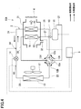
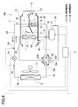
- FIG. 1 is a configuration diagram of a vehicle air conditioner 10A according to the first embodiment of the present invention.
- the vehicle air conditioner 10A is for cooling and heating a vehicle interior (not shown), and includes a heat pump circuit 2 for circulating a refrigerant and a control device 5.
- a refrigerant R134a, R410A, HFO-1234yf, CO 2 or the like can be used.
- the heat pump circuit 2 includes a compressor 11, an outdoor heat exchanger 13, an expansion valve 14, a first indoor heat exchanger 15, and a second indoor heat exchanger 16. Further, the heat pump circuit 2 is provided with a four-way valve 12A as switching means, and the flow direction of the refrigerant flowing through the heat pump circuit 2 by the four-way valve 12A is the first direction indicated by the broken line arrow and the second direction indicated by the solid line arrow. Switch between directions. In the first direction, the refrigerant discharged from the compressor 11 passes through the outdoor heat exchanger 13, the expansion valve 14, the first indoor heat exchanger 15, and the second indoor heat exchanger 16 in this order and returns to the compressor 11.
- the refrigerant discharged from the compressor 11 passes through the first indoor heat exchanger 15, the expansion valve 14, the outdoor heat exchanger 13 and the second indoor heat exchanger 16 in this order and is compressed.
- the direction is to return to the machine 11. That is, both the cooling operation (first direction) and the heating operation (second direction) can be performed with a simple configuration in which the single expansion valve 14 is controlled.
- the four-way valve 12A includes a first state in which the first port 12a communicates with the second port 12b and the third port 12c communicates with the fourth port 12d, and the first port 12a communicates with the third port 12c and the second port
- the port 12b is configured to be shiftable to the second state communicating with the fourth port 12d.
- the four-way valve 12A is shifted by the control device 5 to the first state during the cooling operation and shifted to the second state during the heating operation.
- the compressor 11 is driven by an electric motor (not shown), compresses the refrigerant sucked from the suction port, and discharges it from the discharge port.
- the discharge port of the compressor 11 is connected to the first port 12a of the four-way valve 12A via the first pipe 21.
- the outdoor heat exchanger 13 is disposed, for example, at the front of an automobile, and performs heat exchange between the running of the vehicle and the outside air (air outside the passenger compartment) supplied by the outdoor fan 17 and the refrigerant.
- the outdoor heat exchanger 13 is connected to the second port 12b of the four-way valve 12A via the second pipe 22.
- the expansion valve 14 expands the refrigerant and is an example of the expansion mechanism of the present invention.
- a positive displacement expander that recovers power from the expanding refrigerant may be employed.
- the expansion valve 14 is connected to the outdoor heat exchanger 13 via the third pipe 23.
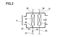
- the first indoor heat exchanger 15 and the second indoor heat exchanger 16 exchange heat between the air sent to the vehicle interior by the indoor fan 4 and the refrigerant.
- the first indoor heat exchanger 15 is connected to the expansion valve 14 via a fourth pipe 24 and is connected to the third port 12 c of the four-way valve 12 ⁇ / b> A via a fifth pipe 25.
- the second indoor heat exchanger 16 is connected to the fourth port 12d of the four-way valve 4 via a sixth pipe 26 and is connected to the suction port of the compressor 11 via a seventh pipe 27.
- the seventh pipe 27 is provided with an accumulator 18.
- the first indoor heat exchanger 15 and the second indoor heat exchanger 16 are arranged in a duct 31 through which air in the vehicle compartment is flowed by the indoor fan 4. That is, the air in the passenger compartment circulates through the duct 31.
- the duct 31 is provided with a drain discharge pipe 32 for discharging moisture separated from the circulation air in the passenger compartment to the outside of the passenger compartment.
- the air flowing through the duct 31 by the indoor fan 4 does not necessarily need to be 100% of the vehicle interior air, and may include some outside air for vehicle interior ventilation, or may be all outside air.
- the air taken into the duct 31 by the indoor fan 4 and supplied to the first indoor heat exchanger 15 and the second indoor heat exchanger 16 is 100% of the vehicle interior air.
- the second indoor heat exchanger 16 is positioned upstream of the first indoor heat exchanger 15 so as to be aligned with the first indoor heat exchanger 15 in the air flow direction in the duct 31. Yes. Both the second indoor heat exchanger 16 and the first indoor heat exchanger 15 have a size that fills the space in the duct 31. For this reason, the vehicle interior air taken into the duct 31 by the indoor fan 4 contacts the second indoor heat exchanger 16 and then contacts the first indoor heat exchanger 15.
- the indoor fan 4 may be arranged on the outlet side of the duct 31 as shown in FIG. 1 or may be arranged on the inlet side of the duct 31 as shown in FIG. Further, as the indoor fan 4, a blower may be used.
- the seventh pipe 27 connecting the second indoor heat exchanger 16 and the suction port of the compressor 11 is provided with a superheat degree sensor 62 that detects the temperature of the refrigerant flowing out of the second indoor heat exchanger 16 (in the present invention).
- a pressure sensor 61 for detecting the pressure of the refrigerant sucked into the compressor 11 is provided.
- the superheat degree sensor 62 is disposed in the duct 31, but may be disposed outside the duct 31. Further, the pressure sensor 61 may be provided in the sixth pipe 26.
- the control device 5 is connected to an operation panel (not shown) disposed in the vehicle interior, and a superheat degree sensor 62 and a pressure sensor 61, and drives the outdoor fan 17 and the indoor fan 4 described above.
- the rotational speed and the opening degree of the expansion valve 14 are controlled, and the four-way valve 12A is shifted.
- the four-way valve 12A is shifted to the second state by the control device 5, and the high-temperature and high-pressure gas refrigerant compressed by the compressor 11 flows through the four-way valve 12A in the direction of the solid arrow.
- the gas refrigerant radiates and condenses the vehicle interior circulation air supplied by the indoor fan 4 in the first indoor heat exchanger 15 and heats the vehicle interior circulation air.
- the liquid refrigerant is throttled by the expansion valve 14 and adiabatically expanded to become a low temperature and low pressure, and then the liquid refrigerant absorbs heat from the outside air and partially evaporates.
- the refrigerant that has flowed out of the outdoor heat exchanger 13 flows again into the second indoor heat exchanger 16 through the four-way valve 12A, absorbs heat from the vehicle interior circulating air supplied by the indoor fan 4, and the remaining liquid refrigerant evaporates.
- the circulating air in the passenger compartment is cooled.
- dew condensation water is generated on the surface of the second indoor heat exchanger 16, and the circulating air in the passenger compartment is dehumidified.
- the generated condensed water is dropped on a drain pan (not shown) provided in the duct 31 and is discharged outside the vehicle compartment through the drain discharge pipe 32.
- the gas refrigerant flowing out from the second indoor heat exchanger 16 is again sucked into the compressor 11.
- the vehicle interior circulating air taken into the duct 31 by the indoor fan 4 in this way is dehumidified by passing through the second indoor heat exchanger 16, and then passes through the first indoor heat exchanger 15. Heated. Thereby, heating can be performed while dehumidifying the circulating air in the passenger compartment.
- FIG. 2 shows a Mollier diagram when the vehicle air conditioner 10A of the present embodiment performs the heating operation. Below, each process of the cycle of FIG. 2 is demonstrated.
- the low-temperature and low-pressure refrigerant (state A) is compressed by the compressor 11 and becomes a high-temperature and high-pressure (state B).
- the high-temperature and high-pressure refrigerant dissipates heat in the first indoor heat exchanger 15 and becomes a medium-temperature and high-pressure (state C).
- the medium-temperature and high-pressure refrigerant passes through the expansion valve 14 and becomes a low-temperature and low-pressure gas-liquid two-phase refrigerant (state D).
- the gas-liquid two-phase refrigerant absorbs heat and evaporates in the process of passing through the outdoor heat exchanger 13 (state E).
- the refrigerant that has passed through the outdoor heat exchanger 13 takes away the amount of heat of latent heat from the air in the vehicle interior.
- State A That is, the amount of heat radiated in the first indoor heat exchanger 15 (change from state B to state C) can be increased by latent heat (change from state E to state A), and the second indoor heat exchanger 16 can be increased.
- the latent heat of moisture in the air collected in step 1 can be used for heating.
- the four-way valve 12A is shifted to the first state by the control device 5, and the high-temperature and high-pressure gas refrigerant compressed by the compressor 11 flows through the four-way valve 12A in the direction of the dashed arrow.
- the gas refrigerant radiates heat to the outside air in the outdoor heat exchanger 13 and condenses.
- the liquid refrigerant is throttled by the expansion valve 14 and adiabatically expanded to become a low temperature and low pressure.
- the liquid refrigerant absorbs heat from the vehicle interior circulating air supplied by the indoor fan 4 in the first indoor heat exchanger 15 and partially evaporates.
- the circulating air in the passenger compartment is cooled.
- the refrigerant that has flowed out of the first indoor heat exchanger 15 flows again into the second indoor heat exchanger 16 through the four-way valve 12A, absorbs heat from the vehicle interior circulating air supplied by the indoor fan 4, and remains as the remaining liquid refrigerant. Evaporates and cools the circulating air in the passenger compartment.
- the pressure is reduced by an amount corresponding to the pressure loss, so that the evaporation temperature in the second indoor heat exchanger 16 is the evaporation temperature in the first indoor heat exchanger 15. Lower than.
- the vehicle interior circulating air is mainly dehumidified by the second indoor heat exchanger 16.
- the gas refrigerant flowing out from the second indoor heat exchanger 16 is again sucked into the compressor 11.
- the vehicle interior circulating air thus taken into the duct 31 by the indoor fan 4 is cooled by passing through the second indoor heat exchanger 16 and the first indoor heat exchanger 15. Cooling capacity and efficiency of the refrigeration cycle can be improved by cooling the circulating air in the passenger compartment with the two heat exchangers of the second indoor heat exchanger 16 and the first indoor heat exchanger 15.
- the dryness of the refrigerant flowing out of the second indoor heat exchanger 16 changes with a change in the traveling speed of the vehicle or a change in the temperature setting in the passenger compartment of the user.
- the degree of superheat which is the temperature difference between the temperature of the refrigerant flowing out of the second indoor heat exchanger 16 and the saturation temperature at the pressure of the refrigerant sucked into the compressor 11, is greater than a predetermined value (eg, 3 to 5 ° C.).
- a predetermined value eg, 3 to 5 ° C.
- the degree of superheat exceeds a predetermined value (for example, 5 to 7 ° C.)
- the COP coefficient of performance
- the amount of refrigerant circulation is important for heat pump capacity control.
- the refrigerant circulation amount depends on the rotation speed of the compressor 11, if the rotation speed of the compressor 11 is excessively high, the discharge pressure and the discharge temperature rise and the risk of exceeding the pressure and temperature at which reliability can be ensured increases. . That is, if the pressure of the refrigerant discharged from the compressor 11 becomes too high, a load is applied to the hermetic container or mechanism that constitutes the compressor 11, and these may be damaged. Further, if the temperature of the refrigerant discharged from the compressor 11 becomes too high, it may exceed the heat resistance temperature of the insulating film of the winding of the drive motor of the compressor 11.
- control device 5 controls the rotation speed of the compressor 11 and the opening degree of the expansion valve 14 based on the required capacity and the degree of superheat according to the input on the operation panel, etc. The cycle state is maintained.
- the control device 5 controls the rotational speed of the compressor 11 within a range in which the discharge temperature of the compressor 11 does not exceed a predetermined temperature (for example, 100 ° C.) according to the required capacity.
- a predetermined temperature for example, 100 ° C.
- an upper limit of the rotational speed of the compressor 11 may be determined in advance, or a discharge temperature sensor is provided in the first pipe 21, and the refrigerant discharged from the compressor 11 by this discharge temperature sensor The temperature may be monitored.
- control device 5 has a storage unit (not shown), and a saturation temperature corresponding to the refrigerant pressure is stored in the storage unit.
- the control device 5 reads the saturation temperature at the pressure detected by the pressure sensor 61 from the storage unit at appropriate times, compares the read saturation temperature with the refrigerant temperature detected by the superheat temperature sensor 62, and the temperature difference between them.
- the degree of opening of the expansion valve 14 is controlled so as to be a predetermined degree of superheat.
- the controller 5 discharges at an appropriate rotational speed of the compressor 11 while keeping the superheat degree of the refrigerant sucked in the compressor 11 constant by the appropriate opening degree of the expansion valve 14.
- the temperature of the refrigerant can be kept below a predetermined temperature. As a result, the optimal cycle state of the heat pump can be maintained.
- the expansion valve 14 can arbitrarily determine the opening degree from fully closed to fully open by driving the valve by the rotation of the stepping motor.
- a 0 to 480 pulse signal is input to the stepping motor.
- the expansion valve 14 is opened to the initial opening PLS0 set from the required capacity at the start of the cooling operation and the heating operation.
- the initial opening PLS0 is set to, for example, 16.7% (80 steps), 20.8% (100 steps), and 25% (120 steps) according to the required capacity.
- the opening corresponding to the minute step ⁇ PLS is changed every 30 seconds, for example.
- the minute step ⁇ PLS is calculated from the saturation temperature Tsat at the pressure of the refrigerant sucked into the compressor 11 and the suction temperature of the compressor 11 (that is, the refrigerant temperature detected by the superheat sensor 62) Ts, for example: 1), the temperature difference between Tsat and Ts can be determined to be 5 ° C.
- ⁇ PLS (Tsat) ⁇ (Ts) +5 (Formula 1)
- the cooling operation and the heating operation can be instantaneously switched only by shifting the four-way valve 12A.
- the circulating air in the passenger compartment is dehumidified by the second indoor heat exchanger 16 during the heating operation, and the evaporation temperature in the second indoor heat exchanger 16 is also the first indoor heat exchanger during the cooling operation as described above. Since the temperature is lower than the evaporation temperature at 15, the temperature is dehumidified mainly by the second indoor heat exchanger 16.
- the second indoor heat exchanger 16 since the second indoor heat exchanger 16 always contributes to dehumidification, the indoor environment due to the evaporation of the condensed water covering the surface of the second indoor heat exchanger 16 even when switching from the cooling operation to the heating operation. Deterioration and fogging of the front window can be prevented.
- the refrigerant is confined in the flow path including the indoor heat dissipation heat exchanger 106 that becomes a closed space during the cooling operation.
- the refrigeration oil stays and the oil necessary for the compressor cannot be secured, which hinders operation. For this reason, when the outside air temperature rises, there is a possibility that the equipment constituting the flow path may be damaged by the increase in the pressure of the trapped refrigerant.
- the cooling operation and the heating operation can be executed with a simple configuration of controlling the four-way valve and the single expansion mechanism.
- the saturation temperature corresponding to the refrigerant pressure is stored in the storage unit of the control device 5, and the control device 5 reads the saturation temperature at the pressure detected by the pressure sensor 61 from the storage unit.
- the invention is not limited to this. For example, using the fact that the refrigerant between the expansion valve 14 and the evaporator (the outdoor heat exchanger 13 for heating operation, the first indoor heat exchanger 15 for cooling operation) is in a gas-liquid two-phase state. A saturation temperature may be acquired.
- the first gas-liquid refrigerant temperature sensor 63 is connected to the third pipe 23 that connects the expansion valve 14 and the outdoor heat exchanger 13, and the expansion valve 14 and the first indoor heat exchanger 15.
- a second gas-liquid refrigerant temperature sensor 64 is provided in the fourth pipe 24 connecting the two.
- the control device 5 can use the detection value of the first gas-liquid refrigerant temperature sensor 63 during the heating operation as the saturation temperature and the detection value of the second gas-liquid refrigerant temperature sensor 24 during the cooling operation.
- a saturation temperature sensor 65 that detects the temperature of the refrigerant flowing into the second indoor heat exchanger 16 is provided in the sixth pipe 26, and the detected value of the saturation temperature sensor 65 is used as the saturation temperature. May be.
- the temperature of the evaporator is constant while the liquid refrigerant is changed to the gas refrigerant in the evaporator (the outdoor heat exchanger 13 in the heating operation, the first indoor heat exchanger 15 in the cooling operation), It is also possible to use the evaporator temperature instead of the saturation temperature.
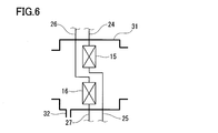
- first indoor heat exchanger 15 and the second indoor heat exchanger 16 do not necessarily have to be arranged in the air flow direction in the duct 31, and for example, as shown in FIG. You may line up in the direction orthogonal to a flow direction.
- the sixth pipe 26 and the seventh pipe 27 are connected by a bypass path 19 with an on-off valve 19a so as to bypass the second indoor heat exchanger 16, and dehumidification is performed during heating operation.
- the on-off valve 19a may be opened. In this way, it is possible to prevent the air from being cooled in the duct 31 and to prevent the refrigerant pressure sucked into the compressor 11 from being reduced due to the pressure loss in the second indoor heat exchanger 16.
- the bypass path 19 may connect the second pipe 22 and the seventh pipe 27.
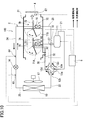
- FIG. 8 is a configuration diagram of a vehicle air conditioner 10B according to the second embodiment of the present invention.
- the same components as those in the first embodiment are denoted by the same reference numerals, and the description thereof is omitted.
- the four-way valve 12A is shifted to the second state, and the flow direction of the refrigerant flowing through the heat pump circuit 2 is switched to the second direction indicated by the solid arrow.
- the four-way valve 12A is shifted to the first state, and the flow direction of the refrigerant flowing through the heat pump circuit 2 is switched to the first direction indicated by the broken line arrow.
- coolant flows become the same as 10 A of vehicle air conditioners of 1st Embodiment shown in FIG.
- R134a, R410A, HFO-1234yf, CO 2 or the like can be used as the refrigerant.
- the second indoor heat exchanger 16 located upstream of the first indoor heat exchanger 15 in the direction of air flow in the duct 31 replaces the second indoor heat exchanger 16 in the duct 31.
- the first flow path 7A passing through and the second flow path 7B not passing through the second indoor heat exchanger 16 are arranged to form a layer.
- the first indoor heat exchanger 15 is exposed to the upstream side from the side of the second indoor heat exchanger 16, in other words, the second indoor heat exchanger 16 is bypassed to the side of the second indoor heat exchanger 16.
- the second indoor heat exchanger 16 may be arranged near the wall surface of the duct 31 so as to ensure a certain space through which air flows.
- a part of the duct 31 surrounding the second indoor heat exchanger 16 may be inflated, and air that bypasses the second indoor heat exchanger 16 may be allowed to flow through the inflated part.
- the duct 31 has a ceiling surface, a bottom surface, and a pair of side surfaces inside, it is preferable that the 2nd indoor heat exchanger 16 is separated from the ceiling surface of the duct 31, and is adjacent to the bottom face side. .
- a damper 71 is provided in the duct 31 on the upstream side of the second indoor heat exchanger 16.
- the damper 71 includes an air volume flowing through the first flow path 7A that reaches the first indoor heat exchanger 15 via the second indoor heat exchanger 16, and the first indoor room without passing through the second indoor heat exchanger 16.
- the ratio of the amount of air flowing through the second flow path 7B reaching the heat exchanger 15 is adjusted.
- a partition plate 72 that is flat in the direction of air flow in the duct 31 is provided in the duct 31 to partition the first flow path 7A and the second flow path 7B.
- the swing shaft of the damper 71 is attached to the end opposite to the one indoor heat exchanger 15.
- the air taken into the duct 31 by the indoor fan 4 is distributed by the damper 71 into a part flowing through the first flow path 7A and a part flowing through the second flow path 7B.
- the air flowing through the first flow path 7A is cooled or dehumidified in contact with the second indoor heat exchanger 16, and then is heated or cooled in contact with the first indoor heat exchanger 15.
- the air flowing through the second flow path B contacts or heats only the first indoor heat exchanger 15. Those airs are blown out from the duct 31 into the vehicle interior.
- the damper 71 is swung by a servo motor (not shown). In order to maximize the dehumidifying performance of the second indoor heat exchanger 16, it is preferable to control the speed of the air passing through the second indoor heat exchanger 16.
- a distribution rate (hereinafter simply referred to as “distribution rate”) to one flow path 7A is determined. For example, when there are three levels of operation notches for the indoor fan 4, high, medium, and low, the distribution ratio is set to three levels of large, medium, and small, and the damper angle is set according to the operation notch of the indoor fan 4. Control. For example, the distribution ratios of large, medium and small are set to 100%, 50% and 25%, respectively.
- the second flow path 7B is closed when the damper 71 is in a high distribution ratio, and the first flow path 7A and the second flow path 7B are when the damper 71 is in the distribution ratio.
- the first flow path 7A is half blocked.
- the damper 71 can adjust the ratio of the amount of air that contacts the second indoor heat exchanger 16 and the amount of air that does not contact the second indoor heat exchanger 16 according to the angle. And in the downstream of the 1st indoor heat exchanger 15, the air which merged them blows off into a vehicle interior.
- the storage unit of the control device 5 stores a table in which the rotation amount of the servo motor that realizes the distribution ratio and the operation notch of the indoor fan 4 are associated with each other, and when the operation notch of the indoor fan 4 is high, the damper 71 is stored. Is set to a state in which the distribution ratio is small, the damper 71 is in the state of distribution ratio when the operation notch of the indoor fan 4 is medium, and the damper 71 is in the state of large distribution ratio when the operation notch of the indoor fan 4 is low. The By such control, the wind speed passing through the second indoor heat exchanger 16 can be made constant.
- the surface of the second indoor heat exchanger 16 is prevented from drying. Can be controlled. Thereby, the latent heat of the water
- Tscsat is 5 ° C.
- Tdh 10 ° C.
- the current distribution rate is 50%
- ⁇ D is ⁇ 2%
- the distribution rate is changed to 48%.
- the cooling operation and the heating operation can be instantaneously switched only by shifting the four-way valve 12A.
- the damper 71 by controlling the amount of air that contacts the second indoor heat exchanger 16 and the amount of air that does not contact the second indoor heat exchanger 16 by the damper 71, the dehumidifying capacity is adjusted in each of the cooling operation and the heating operation. can do.
- the cooling operation and the heating operation can be executed with a simple configuration of controlling the four-way valve and the single expansion mechanism.
- the damper 71 is provided on the windward side of the partition plate 72, but the damper 71 may be provided on the windward side of the partition plate 72.
- the partition plate 72 is provided in the duct 31, even if there is no partition plate 72, the ratio of the airflow which flows through the 1st flow path 7A with the damper 71, and the airflow which flows through the 2nd flow path 7B. It is possible to change. Furthermore, although there is no space between the partition plate 72 and the first indoor heat exchanger 15 in FIG. 8, there may be a space in which air is mixed.
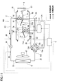
- FIG. 9 is a configuration diagram of a vehicle air conditioner 10C according to the third embodiment of the present invention.
- the same components as those in the first embodiment are denoted by the same reference numerals, and the description thereof is omitted.
- the four-way valve 12A is shifted to the second state, and the flow direction of the refrigerant flowing through the heat pump circuit 2 is switched to the second direction indicated by the solid arrow.
- the four-way valve 12A is shifted to the first state, and the flow direction of the refrigerant flowing through the heat pump circuit 2 is switched to the first direction indicated by the broken line arrow.
- coolant flows become the same as 10 A of vehicle air conditioners of 1st Embodiment shown in FIG.
- R134a, R410A, HFO-1234yf, CO 2 or the like can be used as the refrigerant.
- the first indoor heat exchanger 15 located on the downstream side of the second indoor heat exchanger 16 in the air flow direction in the duct 31 replaces the first indoor heat exchanger 15 in the duct 31.
- the third flow path 7D passing through and the fourth flow path 7D not passing through the first indoor heat exchanger 15 are arranged to form a layer.
- the second indoor heat exchanger 16 is exposed from the side of the first indoor heat exchanger 15 to the downstream side, in other words, the first indoor side of the first indoor heat exchanger 15.
- the first indoor heat exchanger 15 may be arranged near the wall surface of the duct 31 so that a certain space through which air that bypasses the indoor heat exchanger 15 flows is secured.
- a part of the duct 31 surrounding the first indoor heat exchanger 15 may be inflated, and air that bypasses the first indoor heat exchanger 15 may be passed through the inflated part.
- the duct 31 has a ceiling surface, a bottom surface, and a pair of side surfaces inside, it is preferable that the 1st indoor heat exchanger 15 is separated from the ceiling surface of the duct 31, and is adjacent to the bottom surface side. .
- a damper 71 is provided in the duct 31 upstream of the first indoor heat exchanger 15.
- the damper 71 has an air volume flowing through the third flow path 7C that reaches the duct outlet via the first indoor heat exchanger 15, and a fourth flow path that reaches the duct outlet without passing through the first indoor heat exchanger 15.
- the ratio of the air volume flowing through 7D is adjusted.
- a partition plate 72 that is flat in the air flow direction in the duct 31 is provided in the duct 31 to partition the third flow path 7C and the fourth flow path 7D.
- the swing shaft of the damper 71 is attached to the end portion on the two-room heat exchanger 16 side.
- the air taken into the duct 31 by the indoor fan 4 is distributed by the damper 71 into the amount flowing through the third flow path 7C and the amount flowing through the fourth flow path 7D.
- the air flowing through the third flow path 7C is cooled and dehumidified in contact with the second indoor heat exchanger 16, and then heated or cooled in contact with the first indoor heat exchanger 15.
- the air flowing through the fourth flow path 7D is cooled and dehumidified by contacting only the second indoor heat exchanger 16. Those air merges downstream of the first indoor heat exchanger 15 and then blown out from the duct 31 into the vehicle interior.
- the damper 71 is swung by a servo motor (not shown).
- the damper 71 can adjust the ratio of the amount of air that contacts the first indoor heat exchanger 15 and the amount of air that does not contact the first indoor heat exchanger 15 according to the angle. And in the downstream of the 1st indoor heat exchanger 15, the air which merged them blows off into a vehicle interior.
- Tw the temperature of the exhaust air necessary to keep the room temperature at the set temperature
- the cooling operation and the heating operation can be instantaneously switched only by shifting the four-way valve 12A. Further, the temperature of the air at the outlet of the duct 31 can be adjusted by controlling the amount of air that contacts the first indoor heat exchanger 15 and the amount of air that does not contact the first indoor heat exchanger 15 by the damper 71. .
- the cooling operation and the heating operation can be executed with a simple configuration of controlling the four-way valve and the single expansion mechanism.
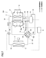
- FIG. 10 is a configuration diagram of a vehicle air conditioner 10D according to the fourth embodiment of the present invention.
- This vehicle air conditioner 10D has a configuration in which the vehicle air conditioner 10B of the second embodiment and the vehicle air conditioner 10C of the third embodiment are combined.
- the second indoor heat exchanger 16 connects the first flow path 7 ⁇ / b> A and the second indoor heat exchanger 16 that pass through the second indoor heat exchanger 16 in the duct 31.
- the first indoor heat exchanger 15 is arranged in a duct 31 with the third flow path 7C passing through the first indoor heat exchanger 15 and the second flow path 7B that does not pass through.
- the fourth flow path 7D that does not pass through the first indoor heat exchanger 15 is arranged so as to form a layer.
- those specific structures are as having demonstrated in 2nd Embodiment and 3rd Embodiment.
- the duct 31 is provided with a first damper 71A for adjusting the ratio of the airflow flowing through the first flow path 7A and the airflow flowing through the second flow path 7B, and the air flow flowing through the third flow path 7C.
- a second damper 71B for adjusting the ratio of the air volume flowing through the fourth flow path 7D is provided.
- the swing axis of the first damper 71A is attached to the windward end of the partition plate 72 that partitions the first flow path 7A and the second flow path 7B, and the swing axis of the second damper 71B is the first It is attached to the windward end of the partition plate 72 that partitions the third flow path 7C and the fourth flow path 7D.
- the air taken into the duct 31 by the indoor fan 4 is distributed by the first damper 71A into the amount flowing through the first flow path 7A and the amount flowing through the second flow path 7B.
- the air flowing through the first flow path 7A contacts the second indoor heat exchanger 16 and is cooled and dehumidified, and then merges with the air flowing through the second flow path 7B.
- the merged air is distributed by the second damper 71B into the amount flowing through the third flow path 7C and the amount flowing through the fourth flow path 7D.
- the air flowing through the third flow path 7C contacts the first indoor heat exchanger 15 and is heated or cooled, and then merges with the air flowing through the fourth flow path 7D.
- the merged air is blown out from the duct 31 into the vehicle interior.
- the first damper 71A and the second damper 71B are swung by a servo motor (not shown).
- the first damper 71 ⁇ / b> A can adjust the ratio of the amount of air that contacts the second indoor heat exchanger 16 and the amount of air that does not contact the second indoor heat exchanger 16 according to the angle.
- the second damper 71B can adjust the ratio of the amount of air that contacts the first indoor heat exchanger 15 and the amount of air that does not contact the first indoor heat exchanger 15 according to the angle.
- the distribution ratio of the first damper 71A to the first flow path 7A is minimized (0%), and the distribution ratio of the second damper 71B to the third flow path 7C is maximized (100%).
- the air taken into the duct 31 by the indoor fan 4 is brought into contact only with the first indoor heat exchanger 15.
- the distribution ratio of the second damper 71B to the third flow path 7C is maximized (100%), while the distribution ratio of the first damper 71A to the first flow path 7A is set to the second heat exchanger 16.
- the distribution ratio to the first flow path 7A by the first damper 71A and the first The distribution ratio to the third flow path 7C by the 2 damper 71B may be set to an intermediate value.
- the distribution ratio of the first damper 71A to the first flow path 7A and the distribution ratio of the second damper 71B to the third flow path 7C are both maximized (100%). That is, the air taken into the duct 31 by the indoor fan 4 is brought into contact with both the second indoor heat exchanger 16 and the first indoor heat exchanger 15.
- the distribution ratio of the first damper 71A to the first flow path 7A is set to an intermediate value at which an appropriate amount of air is supplied to the second heat exchanger 16, and the third flow rate by the second damper 71B.
- the distribution ratio to the path 7C is set to an intermediate value at which an appropriate amount of air is supplied to the first heat exchanger 15.
- the angles of the first damper 71A and the second damper 71B are fixed in accordance with the operation mode as described above, and the air conditioning capability may be adjusted by the rotation speed of the compressor 11.
- the angles of the first damper 71 ⁇ / b> A and the second damper 71 ⁇ / b> B may be changed together with the rotational speed of the compressor 11.
- the wind speed passing through the second indoor heat exchanger 16 is constant as described in the second embodiment.
- the angle of the first damper 71A may be adjusted according to the operation notch of the indoor fan 4 so that Alternatively, in the same manner as described in the second embodiment, the surface of the second indoor heat exchanger 16 is dried in order to reliably recover the latent heat of moisture in the air by the second indoor heat exchanger 16 during the heating operation.
- the angle of the first damper 71A may be adjusted based on the temperature of air detected by the dehumidification temperature sensor 66 and the saturation temperature at the pressure of refrigerant sucked into the compressor 11.
- the temperature of the air detected by the exhaust air temperature sensor 67 is set as described in the third embodiment. Based on this, the angle of the second damper 71B may be adjusted.
- the cooling operation and the heating operation can be executed with a simple configuration of controlling the four-way valve and the single expansion mechanism.
- the second indoor heat exchanger 16 and the first indoor heat exchanger 15 are arranged in the same direction with respect to the partition plate 72, and the first flow path passing through the second indoor heat exchanger 16. 7A and the third flow path 7C passing through the first indoor heat exchanger 15 constitute a continuous flow path.
- the arrangement of the second indoor heat exchanger 16 and the first indoor heat exchanger 15 is not limited to this.
- the second indoor heat exchanger 16 and the first indoor heat exchanger 15 are arranged in opposite directions with respect to the partition plate 72, and pass through the second indoor heat exchanger 16.
- the first flow path 7A and the fourth flow path 7D not passing through the first indoor heat exchanger 15 constitute a continuous flow path
- the third flow path 7C passing through the heat exchanger 15 may constitute a continuous flow path.
- the heating operation and the cooling operation can be performed in an appropriate state according to the capability required.
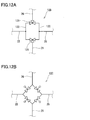
- the four-way valve 12A is used as the switching means, but the switching means of the present invention is not limited to this.
- the switching means as shown in FIG. 12A, two three-way valves 121 connected to the first pipe 21 and the sixth pipe 26 are connected in a loop shape by a pair of pipes 122, and the second pipe 122 is connected to the pipes 122.
- the circuit 12B to which the pipe 22 and the fifth pipe 25 are connected may be used.
- the switching means may be a so-called bridge circuit 12C as shown in FIG. 12B.
- the indoor fan 4 is arranged on the lee of the duct 31.
- air with less turbulence is supplied to the second indoor heat exchanger 16 and the first indoor heat exchanger 15. Can do.
- the pressure loss is reduced, and the fan rotation speed and power consumption can be suppressed.
- the indoor fan 4 may be arranged on the windward side of the duct 31.
- the position of the indoor fan 4 can be kept away from the blower outlet of the duct 31, fan noise can be suppressed.
- the indoor fan 4 by arranging the indoor fan 4 on the windward side of the duct 31, even if the state of the air passing through the indoor fan 4 changes and condensation occurs on the surface of the indoor fan 4, water droplets from the outlet of the duct 31. Can be prevented from jumping out.
- the vehicle air conditioner according to the present invention can enhance the dehumidifying capacity during cooling and improve comfort, and during heating, the window glass can be fogged to ensure visibility, so that it is particularly suitable for non-electric vehicles and fuel cell vehicles. Useful for combustion vehicles.
Landscapes
- Physics & Mathematics (AREA)
- Thermal Sciences (AREA)
- Engineering & Computer Science (AREA)
- Mechanical Engineering (AREA)
- Air-Conditioning For Vehicles (AREA)
Abstract
Description
図1は、本発明の第1実施形態に係る車両用空調装置10Aの構成図である。この車両用空調装置10Aは、図略の車室内の冷房および暖房を行うものであり、冷媒を循環させるヒートポンプ回路2と、制御装置5を備えている。なお、冷媒としては、R134a、R410A、HFO-1234yf、CO2などが利用できる。 (First embodiment)
FIG. 1 is a configuration diagram of a
ΔPLS=(Tsat)-(Ts)+5 ・・・ (式1) The minute step ΔPLS is calculated from the saturation temperature Tsat at the pressure of the refrigerant sucked into the
ΔPLS = (Tsat) − (Ts) +5 (Formula 1)
前記実施形態では、制御装置5の記憶部に冷媒圧力に応じた飽和温度が格納されており、制御装置5が圧力センサ61で検出される圧力における飽和温度を記憶部から読み出していたが、本発明はこれに限定されるものではない。例えば、膨張弁14と蒸発器(暖房運転の場合は室外熱交換器13、冷房運転の場合は第1室内熱交換器15)の間の冷媒が気液二相状態であることを利用して飽和温度を取得するようにしてもよい。 <Modification>
In the embodiment, the saturation temperature corresponding to the refrigerant pressure is stored in the storage unit of the
図8は、本発明の第2実施形態に係る車両用空調装置10Bの構成図である。なお、本実施形態では、第1実施形態と同じ構成には同じ符号を付し、その説明を省略する。 (Second Embodiment)
FIG. 8 is a configuration diagram of a
ΔD=(Tscsat-Tdh+3)/100 ・・・ (式2) By the way, by providing a
ΔD = (Tscsat−Tdh + 3) / 100 (Expression 2)
前記実施形態ではダンパ71を仕切り板72の風上に設けたが、ダンパ71は仕切り板72の風下に設けてもよい。 <Modification>
In the above embodiment, the
図9は、本発明の第3実施形態に係る車両用空調装置10Cの構成図である。なお、本実施形態では、第1実施形態と同じ構成には同じ符号を付し、その説明を省略する。 (Third embodiment)
FIG. 9 is a configuration diagram of a
図10は、本発明の第4実施形態に係る車両用空調装置10Dの構成図である。この車両用空調装置10Dは、第2実施形態の車両用空調装置10Bと第3実施形態の車両用空調装置10Cを組み合わせたような構成を有している。 (Fourth embodiment)
FIG. 10 is a configuration diagram of a
暖房運転時は、四方弁12Aが第2状態にシフトされてヒートポンプ回路2に流れる冷媒の流れ方向が実線矢印で示す第2方向に切り換えられる。 <Heating operation>
During the heating operation, the four-
冷房運転時は四方弁12Aが第1状態にシフトされてヒートポンプ回路2に流れる冷媒の流れ方向が破線矢印で示す第1方向に切り換えられる。 <Cooling operation>
During the cooling operation, the four-
図10では、第2室内熱交換器16と第1室内熱交換器15とが仕切り板72に対して同一の方向に配置されており、第2室内熱交換器16を経由する第1流路7Aと第1室内熱交換器15を経由する第3流路7Cとが連続した流路を構成している。ただし、第2室内熱交換器16と第1室内熱交換器15の配置はこれに限られるものではない。 <Modification>
In FIG. 10, the second
前記各実施形態では、切換手段として四方弁12Aが用いられていたが、本発明の切換手段はこれに限られるものではない。例えば、切換手段は、図12Aに示すような、第1配管21および第6配管26と接続された2つの三方弁121が一対の配管122によってループ状に接続され、それらの配管122に第2配管22および第5配管25が接続された回路12Bであってもよい。あるいは、切換手段は、図12Bに示すようないわゆるブリッジ回路12Cであってもよい。 (Other embodiments)
In each of the above embodiments, the four-
Claims (11)
- 車室内の冷房および暖房を行う車両用空調装置であって、
冷媒を圧縮する圧縮機、前記車室外の空気と冷媒との熱交換を行う室外熱交換器、冷媒を膨張させる膨張機構、ならびにファンによって車室内に送られる空気と冷媒との熱交換を行う第1室内熱交換器および第2室内熱交換器を含むヒートポンプ回路と、
前記ヒートポンプ回路に設けられた、前記ヒートポンプ回路に流れる冷媒の流れ方向を、前記圧縮機から吐出された冷媒が前記室外熱交換器、前記膨張機構、前記第1室内熱交換器および前記第2室内熱交換器をこの順に通過して前記圧縮機に戻る第1方向と、前記圧縮機から吐出された冷媒が前記第1室内熱交換器、前記膨張機構、前記室外熱交換器および前記第2室内熱交換器をこの順に通過して前記圧縮機に戻る第2方向との間で切り換える切換手段と、
を備える車両用空調装置。 A vehicle air conditioner for cooling and heating a passenger compartment,
A compressor that compresses the refrigerant, an outdoor heat exchanger that exchanges heat between the air outside the passenger compartment and the refrigerant, an expansion mechanism that expands the refrigerant, and a heat exchanger that exchanges heat between the air sent to the passenger compartment by the fan and the refrigerant. A heat pump circuit including one indoor heat exchanger and a second indoor heat exchanger;
The refrigerant discharged from the compressor is provided in the heat pump circuit so that the refrigerant flowing in the heat pump circuit flows in the outdoor heat exchanger, the expansion mechanism, the first indoor heat exchanger, and the second indoor A first direction passing through the heat exchanger in this order and returning to the compressor, and the refrigerant discharged from the compressor is the first indoor heat exchanger, the expansion mechanism, the outdoor heat exchanger, and the second indoor Switching means for switching between a second direction passing through the heat exchanger in this order and returning to the compressor;
A vehicle air conditioner. - 内部に前記第1室内熱交換器および前記第2室内熱交換器が配置された、前記ファンにより前記車室内の空気および/または前記車室外の空気が流されるダクトをさらに備える、請求項1に記載の車両用空調装置。 2. The apparatus according to claim 1, further comprising a duct in which the first indoor heat exchanger and the second indoor heat exchanger are disposed, and the air inside the vehicle interior and / or the air outside the vehicle compartment is flowed by the fan. The vehicle air conditioner described.
- 前記第2室内熱交換器は、前記ダクト内の空気の流れ方向において前記第1室内熱交換器と並ぶように前記第1室内熱交換器よりも上流側に位置している、請求項2に記載の車両用空調装置。 The second indoor heat exchanger is located upstream from the first indoor heat exchanger so as to be aligned with the first indoor heat exchanger in the air flow direction in the duct. The vehicle air conditioner described.
- 前記第2室内熱交換器は、前記ダクト内で該第2室内熱交換器を経由する第1流路と該第2室内熱交換器を経由しない第2流路とが層をなすように配置されている、請求項3に記載の車両用空調装置。 The second indoor heat exchanger is disposed in the duct so that a first flow path that passes through the second indoor heat exchanger and a second flow path that does not pass through the second indoor heat exchanger form a layer. The vehicle air conditioner according to claim 3, wherein
- 前記ダクト内には、前記第1流路を流れる風量と前記第2流路を流れる風量の比率を調整するダンパが設けられている、請求項4に記載の車両用空調装置。 The vehicle air conditioner according to claim 4, wherein a damper is provided in the duct for adjusting a ratio of an air volume flowing through the first channel and an air volume flowing through the second channel.
- 前記ダクト内には、前記第1流路と前記第2流路とを仕切る仕切り板が設けられている、請求項5に記載の車両用空調装置。 The vehicle air conditioner according to claim 5, wherein a partition plate that partitions the first flow path and the second flow path is provided in the duct.
- 前記第1室内熱交換器は、前記ダクト内で該第1室内熱交換器を経由する第3流路と該第1室内熱交換器を経由しない第4流路とが層をなすように配置されている、請求項3に記載の車両用空調装置。 The first indoor heat exchanger is disposed in the duct so that a third flow path that passes through the first indoor heat exchanger and a fourth flow path that does not pass through the first indoor heat exchanger form a layer. The vehicle air conditioner according to claim 3, wherein
- 前記第2室内熱交換器は、前記ダクト内で該第2室内熱交換器を経由する第1流路と該第2室内熱交換器を経由しない第2流路とが層をなすように配置されており、
前記第1室内熱交換器は、前記ダクト内で該第1室内熱交換器を経由する第3流路と該第1室内熱交換器を経由しない第4流路とが層をなすように配置されており、
前記ダクト内には、前記第1流路を流れる風量と前記第2流路を流れる風量の比率を調整する第1ダンパが設けられているとともに、前記第3流路を流れる風量と前記第4流路を流れる風量の比率を調整する第2ダンパが設けられている、請求項3に記載の車両用空調装置。 The second indoor heat exchanger is disposed in the duct so that a first flow path that passes through the second indoor heat exchanger and a second flow path that does not pass through the second indoor heat exchanger form a layer. Has been
The first indoor heat exchanger is disposed in the duct so that a third flow path that passes through the first indoor heat exchanger and a fourth flow path that does not pass through the first indoor heat exchanger form a layer. Has been
In the duct, a first damper is provided for adjusting a ratio of an air volume flowing through the first channel and an air volume flowing through the second channel, and the air volume flowing through the third channel and the fourth The vehicle air conditioner according to claim 3, wherein a second damper that adjusts a ratio of an air volume flowing through the flow path is provided. - 前記切換手段を制御することにより、冷房運転時には前記ヒートポンプ回路に流れる冷媒の流れ方向を前記第1方向に切り換え、暖房運転時には前記ヒートポンプ回路に流れる冷媒の流れ方向を前記第2方向に切り換える制御装置をさらに備える、請求項1~8のいずれか一項に記載の車両用空調装置。 A control device that switches the flow direction of the refrigerant flowing through the heat pump circuit during the cooling operation to the first direction and controls the flow direction of the refrigerant flowing through the heat pump circuit during the heating operation by controlling the switching unit. The vehicle air conditioner according to any one of claims 1 to 8, further comprising:
- 前記第2室内熱交換器から流出する冷媒の温度を検出する冷媒温度センサをさらに備え、
前記制御装置は、前記冷媒温度センサで検出される冷媒の温度に基づいて前記膨張機構を制御する、請求項9に記載の車両用空調装置。 A refrigerant temperature sensor for detecting the temperature of the refrigerant flowing out of the second indoor heat exchanger;
The vehicle air conditioner according to claim 9, wherein the control device controls the expansion mechanism based on a refrigerant temperature detected by the refrigerant temperature sensor. - 前記制御装置は、前記圧縮機に吸入される冷媒の圧力での飽和温度と前記冷媒温度センサで検出される冷媒の温度との温度差が所定の過熱度となるように、前記膨張機構を制御する、請求項10に記載の車両用空調装置。 The control device controls the expansion mechanism such that a temperature difference between a saturation temperature at the pressure of the refrigerant sucked into the compressor and a refrigerant temperature detected by the refrigerant temperature sensor becomes a predetermined degree of superheat. The vehicle air conditioner according to claim 10.
Priority Applications (4)
| Application Number | Priority Date | Filing Date | Title |
|---|---|---|---|
| US13/384,684 US9211778B2 (en) | 2010-04-23 | 2011-04-21 | Vehicle air conditioning device |
| CN201180002970.XA CN102470726B (en) | 2010-04-23 | 2011-04-21 | Vehicle air conditioning device |
| EP11771769.4A EP2562017B1 (en) | 2010-04-23 | 2011-04-21 | Vehicle air conditioning device |
| JP2012501063A JP5005122B2 (en) | 2010-04-23 | 2011-04-21 | Air conditioner for vehicles |
Applications Claiming Priority (4)
| Application Number | Priority Date | Filing Date | Title |
|---|---|---|---|
| JP2010-099467 | 2010-04-23 | ||
| JP2010099467 | 2010-04-23 | ||
| JP2010197070 | 2010-09-02 | ||
| JP2010-197070 | 2010-09-02 |
Publications (2)
| Publication Number | Publication Date |
|---|---|
| WO2011132429A1 true WO2011132429A1 (en) | 2011-10-27 |
| WO2011132429A9 WO2011132429A9 (en) | 2011-12-29 |
Family
ID=44833970
Family Applications (1)
| Application Number | Title | Priority Date | Filing Date |
|---|---|---|---|
| PCT/JP2011/002339 WO2011132429A1 (en) | 2010-04-23 | 2011-04-21 | Vehicle air conditioning device |
Country Status (5)
| Country | Link |
|---|---|
| US (1) | US9211778B2 (en) |
| EP (1) | EP2562017B1 (en) |
| JP (1) | JP5005122B2 (en) |
| CN (1) | CN102470726B (en) |
| WO (1) | WO2011132429A1 (en) |
Cited By (8)
| Publication number | Priority date | Publication date | Assignee | Title |
|---|---|---|---|---|
| CN104271373A (en) * | 2012-02-28 | 2015-01-07 | 日本空调系统股份有限公司 | Air conditioning device for vehicle |
| JP2015502293A (en) * | 2011-12-23 | 2015-01-22 | ヴァレオ システム テルミク | Automotive heating and / or air conditioning equipment |
| CN105102249A (en) * | 2013-03-29 | 2015-11-25 | 日本空调系统股份有限公司 | Vehicle air conditioner |
| JP2016517503A (en) * | 2014-04-18 | 2016-06-16 | プソン エンジニアリング コーポレーション | Heat pump system with waste heat recovery structure by secondary evaporator |
| JP2016124474A (en) * | 2015-01-07 | 2016-07-11 | 株式会社デンソー | Refrigeration cycle device |
| WO2017221351A1 (en) * | 2016-06-22 | 2017-12-28 | 三菱電機株式会社 | Dehumidifier |
| JP2021089118A (en) * | 2019-12-06 | 2021-06-10 | 東プレ株式会社 | Freezer and operation method for the same |
| JP2022501785A (en) * | 2018-09-30 | 2022-01-06 | 華為技術有限公司Huawei Technologies Co., Ltd. | Vehicle temperature control system |
Families Citing this family (14)
| Publication number | Priority date | Publication date | Assignee | Title |
|---|---|---|---|---|
| DE102012111672B4 (en) | 2012-04-26 | 2013-12-05 | Visteon Global Technologies, Inc. | Refrigerant circuit of an air conditioning system with heat pump and reheat functionality |
| KR101551213B1 (en) | 2012-08-10 | 2015-09-08 | 엘지전자 주식회사 | Air conditioner for electronic vehicles |
| CN104180556B (en) * | 2013-05-22 | 2017-05-31 | 杭州三花研究院有限公司 | A kind of heat pump type air conditioning system |
| CN103471303B (en) * | 2013-09-29 | 2017-01-25 | Tcl空调器(中山)有限公司 | Air conditioner and anti-condensation method thereof |
| US9702605B2 (en) * | 2013-12-05 | 2017-07-11 | Ford Global Technologies, Llc | Method for adjusting fan and compressor power for a vehicle cabin heating system |
| US10508848B2 (en) * | 2014-03-14 | 2019-12-17 | Mitsubishi Electric Corporation | Refrigeration cycle apparatus |
| US9822752B2 (en) * | 2014-05-19 | 2017-11-21 | Ford Global Technologies, Llc | Vehicle heating system and method |
| CN107351624B (en) * | 2016-05-10 | 2020-08-25 | 比亚迪股份有限公司 | Heat pump air conditioning system and electric automobile |
| CN107356003B (en) | 2016-05-10 | 2021-04-20 | 比亚迪股份有限公司 | Heat pump air conditioning system and electric automobile |
| FR3064945B1 (en) * | 2017-04-05 | 2019-04-19 | Valeo Systemes Thermiques | MOTOR VEHICLE INVERTING INDIRECT AIR CONDITIONING CIRCUIT AND DEFROSTING MODE MANAGEMENT METHOD |
| JP2019163761A (en) * | 2018-03-20 | 2019-09-26 | パナソニックIpマネジメント株式会社 | Gas turbine system |
| JP7099899B2 (en) * | 2018-07-25 | 2022-07-12 | 三菱重工サーマルシステムズ株式会社 | Vehicle air conditioner |
| WO2020255454A1 (en) * | 2019-06-20 | 2020-12-24 | 三菱電機株式会社 | Vehicular air-conditioning device |
| FR3121203B1 (en) * | 2021-03-23 | 2023-02-10 | Psa Automobiles Sa | REVERSIBLE AIR CONDITIONING DEVICE FOR A MOTOR VEHICLE AND METHOD FOR OPERATING SUCH A DEVICE |
Citations (4)
| Publication number | Priority date | Publication date | Assignee | Title |
|---|---|---|---|---|
| JPS6314047A (en) * | 1986-06-28 | 1988-01-21 | 三菱重工業株式会社 | Refrigerant flow controller for air conditioner for automobile |
| JPH07232547A (en) * | 1994-02-25 | 1995-09-05 | Sanden Corp | Air conditioner for vehicle |
| JP2001030743A (en) | 1999-07-26 | 2001-02-06 | Mitsubishi Heavy Ind Ltd | Heat pump air conditioner for electric vehicle |
| JP2003291625A (en) * | 2002-03-29 | 2003-10-15 | Calsonic Kansei Corp | Air conditioner for vehicle |
Family Cites Families (22)
| Publication number | Priority date | Publication date | Assignee | Title |
|---|---|---|---|---|
| GB1098367A (en) * | 1965-06-21 | 1968-01-10 | Ncr Co | Method of fabricating magnetic data storage devices |
| JPS5213025B2 (en) | 1971-10-28 | 1977-04-11 | ||
| JPS4885809A (en) * | 1972-02-22 | 1973-11-13 | ||
| JPH0596940A (en) * | 1991-10-07 | 1993-04-20 | Matsushita Electric Ind Co Ltd | Air-conditioning device for electrically driven automobile |
| JP3198623B2 (en) * | 1992-06-12 | 2001-08-13 | 株式会社デンソー | Air conditioner |
| JP3486851B2 (en) * | 1993-05-28 | 2004-01-13 | 株式会社ゼクセルヴァレオクライメートコントロール | Air conditioner |
| US5526650A (en) * | 1993-09-21 | 1996-06-18 | Nippondenso Co., Ltd. | Air-conditioning apparatus |
| US5598887A (en) | 1993-10-14 | 1997-02-04 | Sanden Corporation | Air conditioner for vehicles |
| JP3410820B2 (en) * | 1994-07-06 | 2003-05-26 | サンデン株式会社 | Vehicle air conditioner |
| JPH08258544A (en) * | 1995-03-22 | 1996-10-08 | Matsushita Electric Ind Co Ltd | Heat pump air-conditioning and heating dehumidifier device for electric vehicle |
| JPH0966736A (en) | 1995-06-23 | 1997-03-11 | Denso Corp | Air conditioner for vehicle |
| JPH10100662A (en) | 1996-09-25 | 1998-04-21 | Calsonic Corp | Air conditioner for automobile |
| FR2769263B1 (en) * | 1997-10-08 | 2000-01-07 | Renault | AIR CONDITIONING AND HEATING SYSTEM FOR A MOTOR VEHICLE |
| US5996360A (en) * | 1997-11-27 | 1999-12-07 | Denso Corporation | Refrigerant cycle system |
| JP2001027455A (en) * | 1999-05-13 | 2001-01-30 | Denso Corp | Heat pump air conditioner |
| US6237357B1 (en) * | 1999-06-07 | 2001-05-29 | Mitsubishi Heavy Industries, Ltd. | Vehicular air conditioner using heat pump |
| JP2002240545A (en) * | 2001-02-20 | 2002-08-28 | Toyota Industries Corp | Air conditioner for vehicle, and method for operating the same |
| DE10126257A1 (en) * | 2001-05-29 | 2002-12-05 | Behr Gmbh & Co | Heating / cooling circuit for an air conditioning system of a motor vehicle, air conditioning system and method for regulating the same |
| AU2003221245A1 (en) * | 2002-01-14 | 2003-07-24 | Behr Gmbh And Co. | Heating/cooling circuit for an air-conditioning system of a motor vehicle, air-conditioning system and a method for controlling the same |
| JP3966044B2 (en) * | 2002-04-02 | 2007-08-29 | 株式会社デンソー | Air conditioner |
| JP4505510B2 (en) | 2007-02-20 | 2010-07-21 | カルソニックカンセイ株式会社 | Vehicle air conditioning system |
| US9346337B2 (en) | 2011-02-24 | 2016-05-24 | Panasonic Intellectual Property Management Co., Ltd. | Air conditioning device for vehicle |
-
2011
- 2011-04-21 CN CN201180002970.XA patent/CN102470726B/en not_active Expired - Fee Related
- 2011-04-21 EP EP11771769.4A patent/EP2562017B1/en not_active Not-in-force
- 2011-04-21 US US13/384,684 patent/US9211778B2/en not_active Expired - Fee Related
- 2011-04-21 WO PCT/JP2011/002339 patent/WO2011132429A1/en active Application Filing
- 2011-04-21 JP JP2012501063A patent/JP5005122B2/en not_active Expired - Fee Related
Patent Citations (4)
| Publication number | Priority date | Publication date | Assignee | Title |
|---|---|---|---|---|
| JPS6314047A (en) * | 1986-06-28 | 1988-01-21 | 三菱重工業株式会社 | Refrigerant flow controller for air conditioner for automobile |
| JPH07232547A (en) * | 1994-02-25 | 1995-09-05 | Sanden Corp | Air conditioner for vehicle |
| JP2001030743A (en) | 1999-07-26 | 2001-02-06 | Mitsubishi Heavy Ind Ltd | Heat pump air conditioner for electric vehicle |
| JP2003291625A (en) * | 2002-03-29 | 2003-10-15 | Calsonic Kansei Corp | Air conditioner for vehicle |
Non-Patent Citations (1)
| Title |
|---|
| See also references of EP2562017A4 * |
Cited By (11)
| Publication number | Priority date | Publication date | Assignee | Title |
|---|---|---|---|---|
| JP2015502293A (en) * | 2011-12-23 | 2015-01-22 | ヴァレオ システム テルミク | Automotive heating and / or air conditioning equipment |
| CN104271373A (en) * | 2012-02-28 | 2015-01-07 | 日本空调系统股份有限公司 | Air conditioning device for vehicle |
| CN105102249A (en) * | 2013-03-29 | 2015-11-25 | 日本空调系统股份有限公司 | Vehicle air conditioner |
| CN105102249B (en) * | 2013-03-29 | 2017-02-15 | 日本空调系统股份有限公司 | Vehicle air conditioner |
| JP2016517503A (en) * | 2014-04-18 | 2016-06-16 | プソン エンジニアリング コーポレーション | Heat pump system with waste heat recovery structure by secondary evaporator |
| JP2016124474A (en) * | 2015-01-07 | 2016-07-11 | 株式会社デンソー | Refrigeration cycle device |
| WO2017221351A1 (en) * | 2016-06-22 | 2017-12-28 | 三菱電機株式会社 | Dehumidifier |
| JPWO2017221351A1 (en) * | 2016-06-22 | 2019-03-22 | 三菱電機株式会社 | Dehumidifier |
| JP2022501785A (en) * | 2018-09-30 | 2022-01-06 | 華為技術有限公司Huawei Technologies Co., Ltd. | Vehicle temperature control system |
| JP7200364B2 (en) | 2018-09-30 | 2023-01-06 | 華為技術有限公司 | vehicle temperature control system |
| JP2021089118A (en) * | 2019-12-06 | 2021-06-10 | 東プレ株式会社 | Freezer and operation method for the same |
Also Published As
| Publication number | Publication date |
|---|---|
| US20120117993A1 (en) | 2012-05-17 |
| EP2562017B1 (en) | 2016-02-10 |
| EP2562017A1 (en) | 2013-02-27 |
| CN102470726B (en) | 2015-05-13 |
| JPWO2011132429A1 (en) | 2013-07-18 |
| EP2562017A4 (en) | 2013-09-25 |
| JP5005122B2 (en) | 2012-08-22 |
| US9211778B2 (en) | 2015-12-15 |
| CN102470726A (en) | 2012-05-23 |
| WO2011132429A9 (en) | 2011-12-29 |
Similar Documents
| Publication | Publication Date | Title |
|---|---|---|
| JP5005122B2 (en) | Air conditioner for vehicles | |
| KR101443645B1 (en) | Air conditoner for electric vehicle | |
| JP6015636B2 (en) | Heat pump system | |
| JP5944154B2 (en) | Air conditioner for vehicles | |
| JP5870903B2 (en) | Refrigeration cycle equipment | |
| JP6041423B2 (en) | Vehicular heat pump system and control method thereof | |
| JP5423528B2 (en) | Heat pump cycle | |
| WO2014188674A1 (en) | Refrigeration cycle device | |
| JP7176405B2 (en) | temperature controller | |
| JP2011140291A (en) | Air conditioner for vehicle | |
| JP2013217631A (en) | Refrigeration cycle device | |
| JP2020142789A (en) | Heat management system | |
| JP5983387B2 (en) | Heat exchanger | |
| WO2013145537A1 (en) | Air conditioner device for vehicle | |
| JPH07232547A (en) | Air conditioner for vehicle | |
| JP5925048B2 (en) | Vehicle air conditioner and vehicle | |
| JP5510374B2 (en) | Heat exchange system | |
| JP5884080B2 (en) | Air conditioner for vehicles | |
| CN110475683B (en) | Air conditioning apparatus | |
| JP4274886B2 (en) | Heat pump air conditioner | |
| JP2021076302A (en) | Refrigeration cycle device | |
| JP2016053434A (en) | Refrigeration cycle device | |
| JP2012076589A (en) | Air conditioner for vehicle | |
| JP2021124235A (en) | Refrigeration cycle device | |
| JP2006116981A (en) | Vehicular air-conditioner |
Legal Events
| Date | Code | Title | Description |
|---|---|---|---|
| WWE | Wipo information: entry into national phase |
Ref document number: 201180002970.X Country of ref document: CN |
|
| 121 | Ep: the epo has been informed by wipo that ep was designated in this application |
Ref document number: 11771769 Country of ref document: EP Kind code of ref document: A1 |
|
| WWE | Wipo information: entry into national phase |
Ref document number: 2012501063 Country of ref document: JP |
|
| WWE | Wipo information: entry into national phase |
Ref document number: 13384684 Country of ref document: US |
|
| WWE | Wipo information: entry into national phase |
Ref document number: 2011771769 Country of ref document: EP |
|
| NENP | Non-entry into the national phase |
Ref country code: DE |