WO2011132336A1 - 電線結合部の保護構造 - Google Patents
電線結合部の保護構造 Download PDFInfo
- Publication number
- WO2011132336A1 WO2011132336A1 PCT/JP2010/068275 JP2010068275W WO2011132336A1 WO 2011132336 A1 WO2011132336 A1 WO 2011132336A1 JP 2010068275 W JP2010068275 W JP 2010068275W WO 2011132336 A1 WO2011132336 A1 WO 2011132336A1
- Authority
- WO
- WIPO (PCT)
- Prior art keywords
- protective
- electric wire
- nonwoven fabric
- wire coupling
- aforementioned
- Prior art date
- Legal status (The legal status is an assumption and is not a legal conclusion. Google has not performed a legal analysis and makes no representation as to the accuracy of the status listed.)
- Ceased
Links
Images


Classifications
-
- H—ELECTRICITY
- H01—ELECTRIC ELEMENTS
- H01R—ELECTRICALLY-CONDUCTIVE CONNECTIONS; STRUCTURAL ASSOCIATIONS OF A PLURALITY OF MUTUALLY-INSULATED ELECTRICAL CONNECTING ELEMENTS; COUPLING DEVICES; CURRENT COLLECTORS
- H01R4/00—Electrically-conductive connections between two or more conductive members in direct contact, i.e. touching one another; Means for effecting or maintaining such contact; Electrically-conductive connections having two or more spaced connecting locations for conductors and using contact members penetrating insulation
- H01R4/70—Insulation of connections
- H01R4/72—Insulation of connections using a heat shrinking insulating sleeve
- H01R4/723—Making a soldered electrical connection simultaneously with the heat shrinking
-
- H—ELECTRICITY
- H01—ELECTRIC ELEMENTS
- H01R—ELECTRICALLY-CONDUCTIVE CONNECTIONS; STRUCTURAL ASSOCIATIONS OF A PLURALITY OF MUTUALLY-INSULATED ELECTRICAL CONNECTING ELEMENTS; COUPLING DEVICES; CURRENT COLLECTORS
- H01R4/00—Electrically-conductive connections between two or more conductive members in direct contact, i.e. touching one another; Means for effecting or maintaining such contact; Electrically-conductive connections having two or more spaced connecting locations for conductors and using contact members penetrating insulation
- H01R4/22—End caps, i.e. of insulating or conductive material for covering or maintaining connections between wires entering the cap from the same end
Definitions
- the present invention relates to a wire harness, and in particular, to a protection structure for an electric wire splice part (electric wire coupling part) in which leading ends of electric wires are connected to each other.
- Patent Documents 1 and 2 Conventionally, a technique for electrically insulating a wire splice part by providing a resin-molded insulating protective cap on the wire splice part is known (for example, Patent Documents 1 and 2).
- the resin-molded protective cap has a fixed shape. That is, the protective cap of the same size is used regardless of the number of wires in the wire splice part. As a result, there arises a problem that the size of the protective cap does not match the number of wires.
- the fixed piece of the protective cap is taped around the wire. Therefore, it can prevent that a protective cap falls off from an electric wire splice part.
- an object of the present invention is to provide a protective structure for the wire coupling portion that can satisfactorily protect the wire coupling portion.
- the wire coupling portion protection structure includes a plurality of wires, a wire coupling portion that electrically connects one ends of the plurality of wires, and the plurality of wires.
- the joint portion of the protective material is joined by cooling and solidifying the melted binder material.
- the protection structure of the electric wire coupling portion according to the second aspect further includes a sandwiching body that sandwiches at least one of the plurality of electric wires with the protective material in the protection structure according to the first aspect. It is characterized by.
- the protective structure of the electric wire coupling part according to the third aspect is the protective structure according to the second aspect, wherein the protective part includes one end vicinity of the plurality of electric wires, the electric wire coupling part, and the sandwiching body.
- the protective material is joined at its joint part in a state where at least one of the plurality of electric wires is sandwiched between the protective material and the sandwiching body while being covered with the protective material. It is characterized by being molded.
- the protective portion is in a state where the vicinity of one end of the plurality of electric wires and the electric wire coupling portion are covered with the protective material, It is formed by joining at its own joint.
- the protective part of the optimal size according to the conditions of an electric wire coupling part and a some electric wire can be shape
- the protective part can be formed with a protective material, and the work man-hour by tape winding can be reduced. Therefore, the manufacturing cost of the protective structure can be suppressed.
- the protection structure of the wire coupling portion according to the second aspect, at least one of the plurality of wires is sandwiched between the sandwiching body and the protective material. Thereby, it can prevent effectively that a some electric wire and electric wire coupling
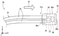
- FIG. 1 is a plan view showing an example of the configuration of the wire harness according to the embodiment of the present invention.
- FIG. 2 is a plan view showing an example of the configuration of the protective structure.
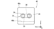
- FIG. 3 is a rear view illustrating an example of the configuration of the protection unit.
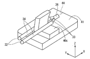
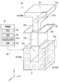
- FIG. 4 is an exploded perspective view showing an example of the configuration of the protection unit.
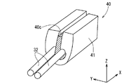
- FIG. 5 is a rear perspective view showing an example of the configuration of the protection unit.
- FIG. 6 is a front perspective view showing an example of the configuration of a mold used for molding the protective part.
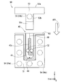
- FIG. 7 is a rear view showing an example of a method for forming the protection part.
- FIG. 8 is a side view showing an example of a method for forming the protection part.
- FIG. 1 is a plan view showing an example of the configuration of the wire harness 10 according to the embodiment of the present invention.
- FIG. 2 is a plan view illustrating an example of the configuration of the protective structure 30.
- the wire harness 10 is a bundle of a plurality of electric wires 22 (see FIG. 1) and electric wires 32 (FIG. 2), and is used for power supply and signal transmission / reception.
- the wire harness 10 mainly includes a main line 20, a protection structure 30, and a protection unit 40.
- the trunk line 20 has a plurality of electric wires 22 and electrically connects connectors 25 (25a, 25b) attached to both ends. And the connector 25 (25a, 25b) of both ends is connected with the connector (illustration omitted) of a corresponding electrical component.
- the fixing portion 26 fixes the splicing lead line 31 to the trunk line 20. Thereby, it is possible to prevent the splicing lead line 31 from interfering with other elements.
- the protective structure 30 is a structure that insulates one end 31 a of the splicing lead wire 31. As shown in FIG. 2, the protection structure 30 mainly includes a splice lead wire 31, a wire coupling portion 36, and a protection portion 40.
- the splicing lead line 31 has a plurality of (in the present embodiment, two for convenience of illustration) electric wires 32 drawn out from the main line 20, and is electrically connected to the main line 20. It is connected. As shown in FIG. 2, each electric wire 32 mainly has a conducting wire 33 and a covering portion 34.
- the conducting wire 33 is a linear body formed of a conductor such as copper or aluminum.
- the covering portion 34 is formed around the conducting wire 33 and protects the conducting wire 33.
- synthetic resin such as polyvinyl chloride, polyethylene, and fluororesin is used.
- the electric wire coupling portion 36 electrically connects one end 31a of each of the plurality of electric wires 32.
- the electric wire coupling portion 36 is formed, for example, by joining one end 31a of each conductive wire 33 by resistance welding, ultrasonic welding, or the like.
- the protection unit 40 is a sheath-like body that protects the vicinity of one end 31a of the splicing lead wire 31. Details of the protection unit 40 will be described later.
- FIGS. 3 to 5 are a rear view, an exploded perspective view, and a rear perspective view, respectively, illustrating an example of the configuration of the protection unit 40.
- the configuration of the protection unit 40 will be described with reference to FIGS. 2 to 5.
- the protection unit 40 protects the vicinity of one end 31a of the plurality of electric wires 32 and the electric wire coupling unit 36.
- the protection part 40 is shape
- the protection part 40 mainly has a main body part 40a, a flange part 40b, and a sandwiching body 40c.
- the nonwoven fabric 41 mainly includes basic fibers formed in a linear shape from PET (polyethylene terephthalate: base material), and binder fibers in which a sheath-like binder material is disposed around the basic fibers. Yes.
- the binder material used in the present embodiment is formed by copolymerization of PET and PEI (polyethylene isophthalate).
- the melting point (second temperature) of the binder material is 110 to 150 ° C., and is set to be lower than that of the base material (PET melting point: about 250 ° C. (first temperature)).
- the main body 40a and the flange 40b are formed by heating and pressurizing the nonwoven fabric 41.
- the shape of the main body 40a is a rounded rectangular parallelepiped or a cube.
- the flange portion 40 b protrudes from the vicinity of the lower portion of the main body portion 40 a in the extending direction D ⁇ b> 1 of the electric wire 32.
- the sandwiching body 40 c is a sheet body that fixes the electric wire 32 to the nonwoven fabric 41.
- the fixing of the electric wire 32 by the sandwiching body 40c is performed as follows. First, as shown in FIG. 4, the sandwiching body 40 c is placed on the nonwoven fabric 41 that is spread in a sheet shape. Next, the sandwiching body 40 c is inserted between the adjacent electric wires 32. Subsequently, the nonwoven fabric 41 is valley-folded at a fold line 44.
- the sandwiching body 40c can sandwich at least one of the plurality of electric wires 32 (may be one, two or more in FIG. 2) with the nonwoven fabric 41. Therefore, it is possible to effectively prevent the plurality of electric wires 32 and the electric wire coupling portion 36 from coming off from the protection portion 40.
- the holding body 40c the same kind as the nonwoven fabric 41 may be used.
- a sheet body formed of a material different from the nonwoven fabric 41 may be used.
- FIG. 6 is a front perspective view showing an example of the configuration of the mold 50 used for molding the protection unit 40.
- 7 and 8 are a rear view and a side view for explaining an example of a method for forming the protection part 40. Below, after explaining the structure of the metal mold
- the metal mold 50 heats and pressurizes one piece of nonwoven fabric 41 (see FIG. 7), thereby forming the nonwoven fabric 41 into a protective portion 40 having a desired shape.
- the mold 50 mainly has a holding part 51, a support plate 52, a compression part 53, and a heater 54.
- the holding portion 51 has a substantially U shape when viewed from the front, and is a holding element that holds the support plate 52.
- the holding space 51 a is formed as a space sandwiched between the side walls 51 b of the holding portion 51.
- the support plate 52 is held by the holding portion 51 in a state of being fitted in the holding space 51a.
- a partition plate 52 b that partitions the arrangement space 52 a is provided on the front side (plus X axis side) of the support plate 52.
- the support plate 52 accommodates the nonwoven fabric 41 to be heated and pressurized.
- the nonwoven fabric 41 is accommodated in the support plate 52 by being folded at the folding line 44 (see FIG. 7) and then inserted into the arrangement space 52a.
- the compression part 53 is a pressurizing element that applies pressure to the nonwoven fabric 41 inserted into the arrangement space 52a. As shown in FIG. 7, the compression part 53 has mainly the flat part 53a, the insertion part 53b, and the protrusion part 53c.
- each of the flat part 53a, the insertion part 53b, and the protrusion part 53c is a substantially rectangular parallelepiped block body.
- the protruding portion 53 c is provided on the insertion portion 53 b so that the shape when combined with the insertion portion 53 b is substantially L-shaped when viewed from the side.
- the insertion portion 53b is provided in the flat portion 53a so that the shape when combined with the flat portion 53a is substantially T-shaped when viewed from the front.
- the insertion portion 53 b and the protruding portion 53 c can be inserted into the arrangement space 52 a of the support plate 52. Therefore, the nonwoven fabric 41 held by the support plate 52 is pressurized by inserting the insertion portion 53b and the protruding portion 53c into the arrangement space 52a (see FIG. 8).
- the protruding portion 53c protrudes toward the arrangement space 52a from the insertion portion 53b.
- the applied pressure to the collar part 40b becomes larger than the applied pressure to the main-body part 40a. Therefore, when the hardness of the main body portion 40a and the flange portion 40b that are pressurized and heated by the mold 50 and then cooled and solidified is compared, the hardness of the flange portion 40b is higher than the hardness of the main body portion 40a.
- the nonwoven fabric 41 can be inserted into the arrangement space 52a using the partition plate 52b provided on the support plate 52 as a reference plane.
- the protrusion 53c and the insertion portion 53b can be inserted into the arrangement space 52a while being guided by the partition plate 52b. Therefore, the compression part 53 can be favorably positioned with respect to the nonwoven fabric 41.
- the heaters 54 are heating elements that heat the nonwoven fabric 41 inserted into the arrangement space 52a. As shown in FIGS. 6 and 7, the holding portion side heater 54a is embedded in the side wall 51b, and the compression portion side heater 54b is embedded in the insertion portion 53b. Therefore, when the heater 54 (54a, 54b) is driven, the nonwoven fabric 41 is heated.
- the control unit 90 realizes heating control and data calculation by the heaters 54 (54a, 54b), for example.
- the control unit 90 mainly includes a ROM 91, a RAM 92, and a CPU 93.
- the control unit 90 is electrically connected to elements of the mold 50 (for example, heaters 54 (54 a, 54 b)) via a signal line 99.
- ROM (Read Only Memory) 91 is a so-called nonvolatile storage unit, and stores, for example, a program 91a.
- a flash memory that is a readable / writable nonvolatile memory may be used.
- a RAM (Random Access Memory) 92 is a volatile storage unit, and stores, for example, data used in the calculation of the CPU 93.
- a CPU (Central Processing93Unit) 93 executes control (for example, heating control of the nonwoven fabric 41) and data processing according to the program 91a of the ROM 91.
- the sandwiching body 40c is adjacent to the nonwoven fabric 41 in a state where it is placed on the nonwoven fabric 41. It is inserted between the electric wires 32 (see FIG. 4).
- the nonwoven fabric 41 is bent around a folding line 44 (see FIG. 7). Thereby, the some electric wire 32 and the electric wire coupling
- the plurality of electric wires 32 and the nonwoven fabric 41 are inserted into the arrangement space 52 a of the support plate 52. Thereby, the one end 31a of the some electric wire 32, the electric wire coupling part 36, and the clamping body 40c are enclosed by the nonwoven fabric 41, and the protection part 40 (refer FIG. 7) before a heating and pressurization is shape
- the holding unit side and compression unit side heaters 54a and 54b are driven by the control unit 90, so that the nonwoven fabric 41 is equal to or higher than the melting point (second temperature) of the binder material and lower than the melting point (first temperature) of the base material. It is heated at a temperature of In addition to the heat treatment, the nonwoven fabric 41 is pressed in the direction of the arrow AR1 (compression direction: see FIG. 7) by the compression unit 53.
- the protection unit 40 in the protection unit 40, the vicinity of the ends 31 a of the plurality of electric wires 32 and the electric wire coupling portion 36 are covered with the nonwoven fabric 41 (if necessary, the nonwoven fabric 41 is further added. In the state where at least one of the plurality of electric wires 32 is sandwiched between the sandwiched body 40c and the sandwiching body 40c), the nonwoven fabric 41 is joined at its joint portion 49.
- the nonwoven fabric 41 according to the conditions for example, conditions, such as the size of the electric wire coupling part 36, the diameter of each electric wire 32, the number of the electric wires 32
- bond part 36 and the some electric wire 32 can be shape
- the wire coupling portion 36 can be protected by the protective portion 40 having the optimum size. Therefore, the size of the protection part 40 can be reduced easily, and the nonwoven fabric 41 (protective material) can be saved.
- the protection part 40 is shape
- the protection part 40 has been described as having the flange part 40b protruding from the main body part 40a, but the shape of the protection part 40 is not limited to this.
- the protection part 40 may not have the collar part 40b.
- the protection part 40 is desired by heating and pressurizing this nonwoven fabric 41.
- molding method of the protection part 40 is not limited to this.
- the protection unit 40 may be formed by, for example, arranging the plurality of electric wires 32 and the electric wire coupling portion 36 between two nonwoven fabrics, and then heating and pressing the two nonwoven fabrics.
- the protection part 40 may be comprised by the 3 or more nonwoven fabric.
Landscapes
- Connections Effected By Soldering, Adhesion, Or Permanent Deformation (AREA)
- Insulated Conductors (AREA)
- Cable Accessories (AREA)
- Details Of Indoor Wiring (AREA)
Abstract
電線結合部の保護構造であって、複数の電線(32)と、前記複数の電線のそれぞれの一端を電気的に接続する電線結合部(36)と、前記複数の電線の一端付近と、前記電線結合部とが、保護材(41)に覆われた状態で、前記保護材が、自身の接合部にて接合されることにより成形される保護部(40)と、を備え、前記保護材は、基材と、前記基材より低融点のバインダ材と、を有するとともに、前記保護材の前記接合部は、溶融した前記バインダ材が冷却凝固することによって、接合される。
Description
本発明は、ワイヤーハーネスに関するものであり、特に、電線の先端部を相互に接続した電線スプライス部(電線結合部)の保護構造に関する。
従来、樹脂成形された絶縁用の保護キャップを電線スプライス部に設けることによって、電線スプライス部を電気的に絶縁する技術が知られている(例えば、特許文献1および2)。
しかし、特許文献1および2において、樹脂成形された保護キャップは、一定形状とされている。すなわち、電線スプライス部における電線の本数によらず、同一サイズの保護キャップが使用される。その結果、電線の本数に対して保護キャップのサイズが合わないという問題が生ずる。
また、電線スプライス部に保護キャップが装着されると、保護キャップの固定片は、電線に対してテープ巻きされる。これにより、保護キャップが電線スプライス部から脱落することを防止できる。
しかしながら、保護キャップを固定(テープ巻き)するための作業工数がさらに必要となり、その結果、製造コストが増大するという問題も生ずる。
そこで、本発明では、電線結合部を良好に保護できる電線結合部の保護構造を提供することを目的とする。
上記の課題を解決するため、第1の態様に係る電線結合部の保護構造は、複数の電線と、前記複数の電線のそれぞれの一端を電気的に接続する電線結合部と、前記複数の電線の一端付近と、前記電線結合部とが、保護材に覆われた状態で、前記保護材が、自身の接合部にて接合されることにより成形される保護部とを備え、前記保護材は、基材と、前記基材より低融点のバインダ材とを有するとともに、前記保護材の前記接合部は、溶融した前記バインダ材が冷却凝固することによって、接合されることを特徴とする。
また、第2の態様に係る電線結合部の保護構造は、第1の態様に係る保護構造において、前記保護材との間で前記複数の電線の少なくとも1本を挟み込む挟持体、をさらに備えることを特徴とする。
また、第3の態様に係る電線結合部の保護構造は、第2の態様に係る保護構造において、前記保護部は、前記複数の電線の一端付近と、前記電線結合部と、前記挟持体とが、保護材に覆われつつ、前記保護材と前記挟持体との間で前記複数の電線の少なくとも1本が挟み込まれた状態で、前記保護材が、自身の接合部にて接合されることにより成形されることを特徴とする。
第1の態様ないし第3態様に係る電線結合部の保護構造によれば、保護部は、複数の電線の一端付近と、電線結合部とが、保護材により覆われた状態で、保護材が自身の接合部にて接合されることにより成形される。これにより、電線結合部および複数の電線の条件に応じた保護材が選択されることによって、電線結合部および複数の電線の条件に応じた最適なサイズの保護部が成形できる。そのため、最適なサイズの保護部によって電線結合部を保護することができる。
また、第1の態様ないし第3態様に係る電線結合部の保護構造によれば、保護部を保護材により成形することができ、テープ巻きによる作業工数を減少させることができる。そのため、保護構造の製造コストを抑制することができる。
特に、第2の態様に係る電線結合部の保護構造によれば、複数の電線のうち少なくとも1本は、挟持体と保護材との間に挟み込まれている。これにより、保護部から複数の電線および電線結合部が抜けることを有効に防止できる。
以下、図面を参照しつつ本発明の実施の形態について詳細に説明する。
<1.ワイヤーハーネスの構成>
図1は、本発明の実施の形態におけるワイヤーハーネス10の構成の一例を示す平面図である。図2は、保護構造30の構成の一例を示す平面図である。ここで、ワイヤーハーネス10は、複数の電線22(図1参照)および電線32(図2)を束にしたものであり、電源供給および信号の送受信に使用される。図1に示すように、ワイヤーハーネス10は、主として、幹線20と、保護構造30と、保護部40と、を有している。
図1は、本発明の実施の形態におけるワイヤーハーネス10の構成の一例を示す平面図である。図2は、保護構造30の構成の一例を示す平面図である。ここで、ワイヤーハーネス10は、複数の電線22(図1参照)および電線32(図2)を束にしたものであり、電源供給および信号の送受信に使用される。図1に示すように、ワイヤーハーネス10は、主として、幹線20と、保護構造30と、保護部40と、を有している。
幹線20は、複数の電線22を有しており、両端に取り付けられたコネクタ25(25a、25b)を電気的に接続する。そして、両端のコネクタ25(25a、25b)は、対応する電装品のコネクタ(図示省略)と接続される。固定部26は、スプライス用引出し線31を幹線20に対して固定する。これにより、スプライス用引出し線31が他の要素と干渉することを防止できる。
保護構造30は、スプライス用引出し線31の一端31aを絶縁する構造である。図2に示すように、保護構造30は、主として、スプライス用引出し線31と、電線結合部36と、保護部40と、を有している。
スプライス用引出し線31は、図2に示すように、幹線20から引き出された複数(本実施の形態では、図示の都合上2本)の電線32を有しており、幹線20と電気的に接続されている。図2に示すように、各電線32は、主として、導線33と、被覆部34と、を有している。
導線33は、例えば銅またはアルミニウム等の導体により形成された線状体である。被覆部34は、導線33の周囲に形成され、導線33を保護する。被覆部34の材料としては、例えば、ポリ塩化ビニル、ポリエチレン、およびフッ素樹脂等の合成樹脂が使用される。
電線結合部36は、複数の電線32のそれぞれの一端31aを電気的に接続する。電線結合部36は、例えば、各導線33の一端31aが抵抗溶接や超音波溶接等により接合されることによって、成形される。
保護部40は、スプライス用引出し線31の一端31a付近を保護する鞘状体である。なお、保護部40の詳細については、後述する。
<2.保護部の構成>
図3から図5は、それぞれ保護部40の構成の一例を示す背面図、分解斜視図、および背面斜視図である。ここでは、図2から図5を参照しつつ、保護部40の構成について説明する。
図3から図5は、それぞれ保護部40の構成の一例を示す背面図、分解斜視図、および背面斜視図である。ここでは、図2から図5を参照しつつ、保護部40の構成について説明する。
保護部40は、複数の電線32の一端31a付近と、電線結合部36とを、保護する。保護部40は、例えば、複数の電線32の一端31a付近と、電線結合部36とが、不織布41(保護材)に覆われた状態で、不織布41が接合されることによって、成形される。図2および図3に示すように、保護部40は、主として、本体部40aと、鍔部40bと、挟持体40cと、を有している。
ここで、不織布41は、主として、PET(ポリエチレンテレフタレート:基材)により線状に形成された基本繊維と、基本繊維の周囲に鞘状のバインダ材が配置されたバインダ繊維と、を有している。
また、本実施の形態で用いられるバインダ材は、PETおよびPEI(ポリエチレンイソフタレート)の共重合により形成されている。また、バインダ材の融点(第2温度)は、110~150℃であり、基材(PETの融点:約250℃(第1温度))より低融点となるように設定されている。
本体部40aおよび鍔部40bは、不織布41を加熱および加圧することによって成形される。図2および図3に示すように、本体部40aの形状は、角丸状の直方体または立方体とされている。鍔部40bは、図2および図3に示すように、本体部40aの下部付近から電線32の延伸方向D1に突出する。
挟持体40cは、不織布41に対して電線32を固定するシート体である。ここで、挟持体40cによる電線32の固定は、以下のようにして行われる。まず、図4に示すように、挟持体40cが、シート状に広げられた不織布41の上に載せ置かれる。次に、隣接する電線32の間に挟持体40cが挿入される。続いて、不織布41が折り曲げ線44で谷折りされる。
これにより、挟持体40cは、不織布41との間で複数の電線32の少なくとも1本(図2では1本、2本以上であっても良い)を挟み込むことができる。そのため、保護部40から複数の電線32および電線結合部36が抜けることが、有効に防止される。
なお、挟持体40cとしては、不織布41と同種のものが使用されても良い。また、不織布41とは相違する材料で成形されたシート体が使用されても良い。
<3.保護部の成形方法>
図6は、保護部40の成形に用いられる金型50の構成の一例を示す正面斜視図である。図7および図8は、保護部40の成形方法の一例を説明するための背面図および側面図である。以下では、まず、金型50の構成を説明した後、保護部40の成形方法を説明する。
図6は、保護部40の成形に用いられる金型50の構成の一例を示す正面斜視図である。図7および図8は、保護部40の成形方法の一例を説明するための背面図および側面図である。以下では、まず、金型50の構成を説明した後、保護部40の成形方法を説明する。
<3.1.金型の構成>
ここでは、金型50のハードウェア構成について説明する。金型50は、1枚の不織布41(図7参照)を加熱および加圧することによって、この不織布41を所望の形状の保護部40に成形する。図6に示すように、金型50は、主として、保持部51と、支持プレート52と、圧縮部53と、ヒータ54と、と有している。
ここでは、金型50のハードウェア構成について説明する。金型50は、1枚の不織布41(図7参照)を加熱および加圧することによって、この不織布41を所望の形状の保護部40に成形する。図6に示すように、金型50は、主として、保持部51と、支持プレート52と、圧縮部53と、ヒータ54と、と有している。
保持部51は、図6に示すように、正面視略U字形状とされており、支持プレート52を保持する保持要素である。保持空間51aは、保持部51の側壁51bに挟まれた空間として形成されている。
支持プレート52は、保持空間51aに嵌め込まれた状態で、保持部51により保持される。図6に示すように、支持プレート52の正面側(プラスX軸側)には、配置空間52aを仕切る仕切板52bが設けられている。
また、図7に示すように、支持プレート52は、加熱および加圧対象となる不織布41を収容する。例えば、不織布41は、折り曲げ線44(図7参照)で折り曲げられた後、配置空間52aに挿入されることによって、支持プレート52に収容される。
圧縮部53は、配置空間52aに挿入された不織布41に対して圧力を付与する加圧要素である。図7に示すように、圧縮部53は、主として、平坦部53aと、挿入部53bと、突出部53cと、を有している。
平坦部53a、挿入部53b、および突出部53cのそれぞれは、略直方体状のブロック体である。突出部53cは、図6に示すように、挿入部53bと組み合わされた場合における形状が側面視略L字状となるように、挿入部53bに設けられている。一方、挿入部53bは、図6に示すように、平坦部53aと組み合わされた場合における形状が正面視略T字状となるように、平坦部53aに設けられている。また、挿入部53bおよび突出部53cは、支持プレート52の配置空間52aに挿入可能とされている。したがって、挿入部53bおよび突出部53cが、配置空間52aに挿入されることによって、支持プレート52で保持された不織布41が、加圧される(図8参照)。
ここで、図6に示すように、突出部53cは、挿入部53bより配置空間52a側に突出している。これにより、鍔部40bへの加圧力は、本体部40aへの加圧力より大きくなる。そのため、金型50により加圧・加熱され、その後に冷却凝固された本体部40aおよび鍔部40bの硬度を比較した場合、鍔部40bの硬度は、本体部40aの硬度より高くなる。
また、不織布41は、支持プレート52に設けられた仕切板52bを基準面として配置空間52a内に挿入できる。一方、突出部53cおよび挿入部53bは、仕切板52bに案内されつつ、配置空間52aに挿入できる。そのため、不織布41に対して圧縮部53を良好に位置決めすることができる。
ヒータ54(54a、54b)は、配置空間52aに挿入された不織布41を加熱する加熱要素である。図6および図7に示すように、保持部側ヒータ54aは側壁51b内に、圧縮部側ヒータ54bは挿入部53b内に、それぞれ埋設されている。したがって、ヒータ54(54a、54b)が駆動させられると、不織布41が加熱される。
制御部90は、例えばヒータ54(54a、54b)による加熱制御、およびデータ演算を実現する。図6に示すように、制御部90は、主として、ROM91と、RAM92と、CPU93と、を有している。また、図6に示すように、制御部90は、信号線99を介して金型50の要素(例えば、ヒータ54(54a、54b))と電気的に接続されている。
ROM(Read Only Memory)91は、いわゆる不揮発性の記憶部であり、例えば、プログラム91aが格納されている。なお、ROM91としては、読み書き自在の不揮発性メモリであるフラッシュメモリが使用されてもよい。
RAM(Random Access Memory)92は、揮発性の記憶部であり、例えば、CPU93の演算で使用されるデータが格納される。CPU(Central Processing Unit)93は、ROM91のプログラム91aに従った制御(例えば、不織布41の加熱制御)やデータ処理を実行する。
<3.2.金型を用いた保護部の成形方法>
ここでは、図3から図7を参照しつつ、金型50を用いた保護部40の成形方法(すなわち、保護部40を有するワイヤーハーネス10の製造方法)について説明する。
ここでは、図3から図7を参照しつつ、金型50を用いた保護部40の成形方法(すなわち、保護部40を有するワイヤーハーネス10の製造方法)について説明する。
なお、本成形方法の開始に先立ち、各電線32および電線結合部36の抜け防止策を講ずる必要がある場合には、挟持体40cが、不織布41の上に載せ置きされた状態で、隣接する電線32の間に挿入される(図4参照)。
まず、不織布41が折り曲げ線44(図7参照)を中心に折り曲げられる。これにより、複数の電線32および電線結合部36が、不織布41により覆われる。また、複数の電線32の少なくとも1本が、不織布41と挟持体40cとの間で挟み込まれる。
次に、複数の電線32および不織布41が、支持プレート52の配置空間52aに挿入される。これにより、複数の電線32の一端31a、電線結合部36、および挟持体40cが不織布41により囲繞され、加熱および加圧前の保護部40(図7参照)が成形される。
続いて、保持部側および圧縮部側ヒータ54a、54bが制御部90により駆動させられることによって、不織布41が、バインダ材の融点(第2温度)以上、基材の融点(第1温度)未満の温度で加熱される。また、不織布41は、加熱処理に加え、圧縮部53により矢印AR1方向(圧縮方向:図7参照)に加圧される。
続いて、ヒータ54(54a、54b)による加熱が停止させられ、保護部40が空冷等により冷却される。これにより、接合部49のバインダ材の一部または全部は、溶融して基材の間を広がった後、冷却凝固する。そして、不織布41は、自身の接合部49にて接合され、保護部40の成形が完了する。
<4.本実施の形態のワイヤーハーネスの利点>
以上のように、本実施の形態において、保護部40は、複数の電線32の一端31a付近と、電線結合部36とが、不織布41により覆われた(必要な場合には、さらに、不織布41と挟持体40cとの間で複数の電線32の少なくとも1本が挟み込まれた)状態で、不織布41が自身の接合部49にて接合されることにより成形される。
以上のように、本実施の形態において、保護部40は、複数の電線32の一端31a付近と、電線結合部36とが、不織布41により覆われた(必要な場合には、さらに、不織布41と挟持体40cとの間で複数の電線32の少なくとも1本が挟み込まれた)状態で、不織布41が自身の接合部49にて接合されることにより成形される。
これにより、電線結合部36および複数の電線32の条件(例えば、電線結合部36のサイズ、各電線32の直径、電線32の本数等の条件)に応じた不織布41が選択されることによって、電線結合部36および複数の電線32に応じた最適なサイズの保護部40を成形することができる。
このように、最適なサイズの保護部40によって電線結合部36を保護することができる。そのため、保護部40のサイズを容易に縮小させることができ、不織布41(保護材)を節約することができる。
また、本実施の形態において、保護部40は、不織布41により成形されており、テープ巻きによる作業工数を減少させることができる。そのため、ワイヤーハーネス10全体の製造コストを抑制することができる。
<5.変形例>
以上、本発明の実施の形態について説明してきたが、本発明は上記実施の形態に限定されるものではなく様々な変形が可能である。
以上、本発明の実施の形態について説明してきたが、本発明は上記実施の形態に限定されるものではなく様々な変形が可能である。
(1)本実施の形態において、保護部40は、本体部40aから突出する鍔部40bを有するものとして説明したが、保護部40の形状はこれに限定されない。例えば、保護部40は、鍔部40bを有さないものであっても良い。
(2)また、本実施の形態において、保護部40は、1枚の不織布41の内側に複数の電線32および電線結合部36を配置した後、この不織布41を加熱および加圧することによって、所望の形状に成形されるものとして説明したが、保護部40の成形方法はこれに限定されるものでない。保護部40は、例えば、2枚の不織布の間に複数の電線32および電線結合部36を配置した後、これら2枚の不織布を加熱および加圧することによって、成形されても良い。また、保護部40は、3枚以上の不織布により構成されても良い。
10 ワイヤーハーネス
20 幹線
22、32 電線
30 保護構造
31 スプライス用引出し線
31a 一端
33 導線
34 被覆部
36 電線結合部
40 保護部
40a 本体部
40b 鍔部
40c 挟持体
41 不織布
44 折り曲げ線
49 接合部
50 金型
51 保持部
52 支持プレート
52a 配置空間
52b 仕切板
53 圧縮部
53a 平坦部
53b 挿入部
53c 突出部
54(54a、54b) ヒータ
90 制御部
20 幹線
22、32 電線
30 保護構造
31 スプライス用引出し線
31a 一端
33 導線
34 被覆部
36 電線結合部
40 保護部
40a 本体部
40b 鍔部
40c 挟持体
41 不織布
44 折り曲げ線
49 接合部
50 金型
51 保持部
52 支持プレート
52a 配置空間
52b 仕切板
53 圧縮部
53a 平坦部
53b 挿入部
53c 突出部
54(54a、54b) ヒータ
90 制御部
Claims (3)
- (a) 複数の電線と、
(b) 前記複数の電線のそれぞれの一端を電気的に接続する電線結合部と、
(c) 前記複数の電線の一端付近と、前記電線結合部とが、保護材に覆われた状態で、前記保護材が、自身の接合部にて接合されることにより成形される保護部と、
を備え、
前記保護材は、
(c-1) 基材と、
(c-2) 前記基材より低融点のバインダ材と、
を有するとともに、
前記保護材の前記接合部は、溶融した前記バインダ材が冷却凝固することによって、接合されることを特徴とする電線結合部の保護構造。 - 請求項1に記載の保護構造において、
(d) 前記保護材との間で前記複数の電線の少なくとも1本を挟み込む挟持体、
をさらに備えることを特徴とする電線結合部の保護構造。 - 請求項2に記載の保護構造において、
前記保護部は、前記複数の電線の一端付近と、前記電線結合部と、前記挟持体とが、保護材に覆われつつ、前記保護材と前記挟持体との間で前記複数の電線の少なくとも1本が挟み込まれた状態で、前記保護材が、自身の接合部にて接合されることにより成形されることを特徴とする電線結合部の保護構造。
Applications Claiming Priority (2)
| Application Number | Priority Date | Filing Date | Title |
|---|---|---|---|
| JP2010-097684 | 2010-04-21 | ||
| JP2010097684A JP2011228155A (ja) | 2010-04-21 | 2010-04-21 | 電線結合部の保護構造 |
Publications (1)
| Publication Number | Publication Date |
|---|---|
| WO2011132336A1 true WO2011132336A1 (ja) | 2011-10-27 |
Family
ID=44833886
Family Applications (1)
| Application Number | Title | Priority Date | Filing Date |
|---|---|---|---|
| PCT/JP2010/068275 Ceased WO2011132336A1 (ja) | 2010-04-21 | 2010-10-18 | 電線結合部の保護構造 |
Country Status (2)
| Country | Link |
|---|---|
| JP (1) | JP2011228155A (ja) |
| WO (1) | WO2011132336A1 (ja) |
Cited By (1)
| Publication number | Priority date | Publication date | Assignee | Title |
|---|---|---|---|---|
| WO2013190725A1 (ja) * | 2012-06-21 | 2013-12-27 | 住友電装株式会社 | ワイヤーハーネス及びその製造方法 |
Families Citing this family (1)
| Publication number | Priority date | Publication date | Assignee | Title |
|---|---|---|---|---|
| JP6030888B2 (ja) * | 2012-08-23 | 2016-11-24 | 矢崎総業株式会社 | 電線溶接方法及び電線溶接装置 |
Citations (2)
| Publication number | Priority date | Publication date | Assignee | Title |
|---|---|---|---|---|
| JPS6332882A (ja) * | 1986-07-25 | 1988-02-12 | 三菱電機株式会社 | 高電圧機器線輪接続部の絶縁方法 |
| JPH11242968A (ja) * | 1998-02-25 | 1999-09-07 | Yazaki Corp | 防水保護カバー |
-
2010
- 2010-04-21 JP JP2010097684A patent/JP2011228155A/ja active Pending
- 2010-10-18 WO PCT/JP2010/068275 patent/WO2011132336A1/ja not_active Ceased
Patent Citations (2)
| Publication number | Priority date | Publication date | Assignee | Title |
|---|---|---|---|---|
| JPS6332882A (ja) * | 1986-07-25 | 1988-02-12 | 三菱電機株式会社 | 高電圧機器線輪接続部の絶縁方法 |
| JPH11242968A (ja) * | 1998-02-25 | 1999-09-07 | Yazaki Corp | 防水保護カバー |
Cited By (1)
| Publication number | Priority date | Publication date | Assignee | Title |
|---|---|---|---|---|
| WO2013190725A1 (ja) * | 2012-06-21 | 2013-12-27 | 住友電装株式会社 | ワイヤーハーネス及びその製造方法 |
Also Published As
| Publication number | Publication date |
|---|---|
| JP2011228155A (ja) | 2011-11-10 |
Similar Documents
| Publication | Publication Date | Title |
|---|---|---|
| JP5392171B2 (ja) | ワイヤーハーネスおよびその製造方法 | |
| US9570212B2 (en) | Wire harness and method for manufacturing wire harness | |
| US11322270B2 (en) | Wire harness and method of manufacturing wire harness | |
| CN103141001A (zh) | 线束及其制造方法 | |
| CN110277195A (zh) | 线束和具有线束的片材的制造方法 | |
| JP5644542B2 (ja) | ワイヤハーネス | |
| JP5353814B2 (ja) | ワイヤーハーネスの保護構造 | |
| JP5359984B2 (ja) | コネクタの保護構造およびその製造方法 | |
| JP7088696B2 (ja) | 電線接続構造及び電線接続構造の製造方法 | |
| JP5526927B2 (ja) | ワイヤハーネス及びその製造方法 | |
| JP5601213B2 (ja) | ワイヤハーネス | |
| WO2011132336A1 (ja) | 電線結合部の保護構造 | |
| US10137847B2 (en) | Exterior wiring harness | |
| JP6673399B2 (ja) | 配線部材の固定構造 | |
| JP2012115019A (ja) | ワイヤハーネス | |
| JP2004273369A (ja) | ワイヤーハーネスの伸縮規制構造およびワイヤーハーネスの布線方法 | |
| JP5447173B2 (ja) | コネクタの固定構造 | |
| WO2014129011A1 (ja) | ワイヤーハーネス及びワイヤーハーネスの製造方法 | |
| JP5750290B2 (ja) | ワイヤハーネスの成形用治具およびワイヤハーネスの製造方法 | |
| JP5556606B2 (ja) | 被覆部材付電線束および被覆部材付電線束の製造方法 | |
| JP2017107657A (ja) | ワイヤハーネス | |
| JP2013236469A (ja) | ワイヤーハーネス | |
| JP2025139632A (ja) | ワイヤハーネス、及び、外装部材 | |
| JP2004063280A (ja) | 平型配線材とフレキシブルプリント配線材の接続構造及びその製造方法 |
Legal Events
| Date | Code | Title | Description |
|---|---|---|---|
| 121 | Ep: the epo has been informed by wipo that ep was designated in this application |
Ref document number: 10850277 Country of ref document: EP Kind code of ref document: A1 |
|
| NENP | Non-entry into the national phase |
Ref country code: DE |
|
| 122 | Ep: pct application non-entry in european phase |
Ref document number: 10850277 Country of ref document: EP Kind code of ref document: A1 |